Effect of Pre-Combustion Chamber Nozzle Parameters on the Performance of a Marine 2-Stroke Dual Fuel Engine

Abstract
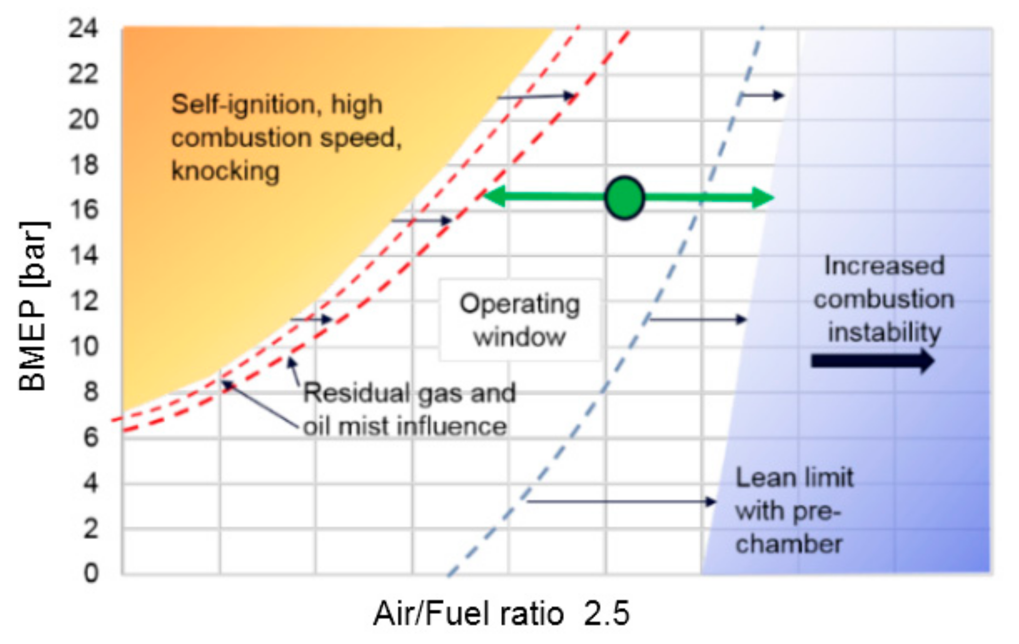
:1. Introduction
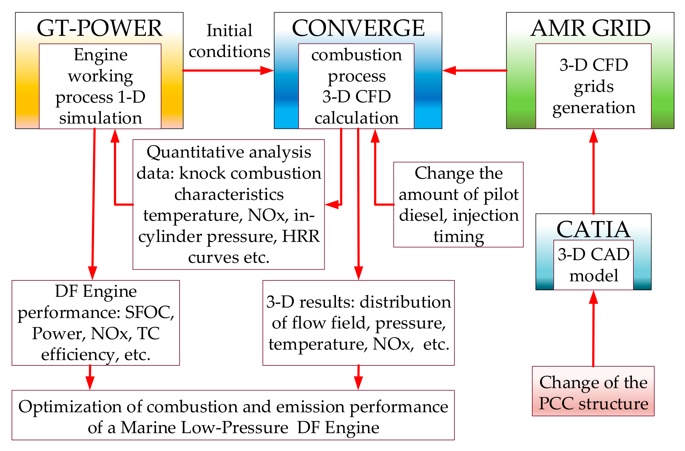
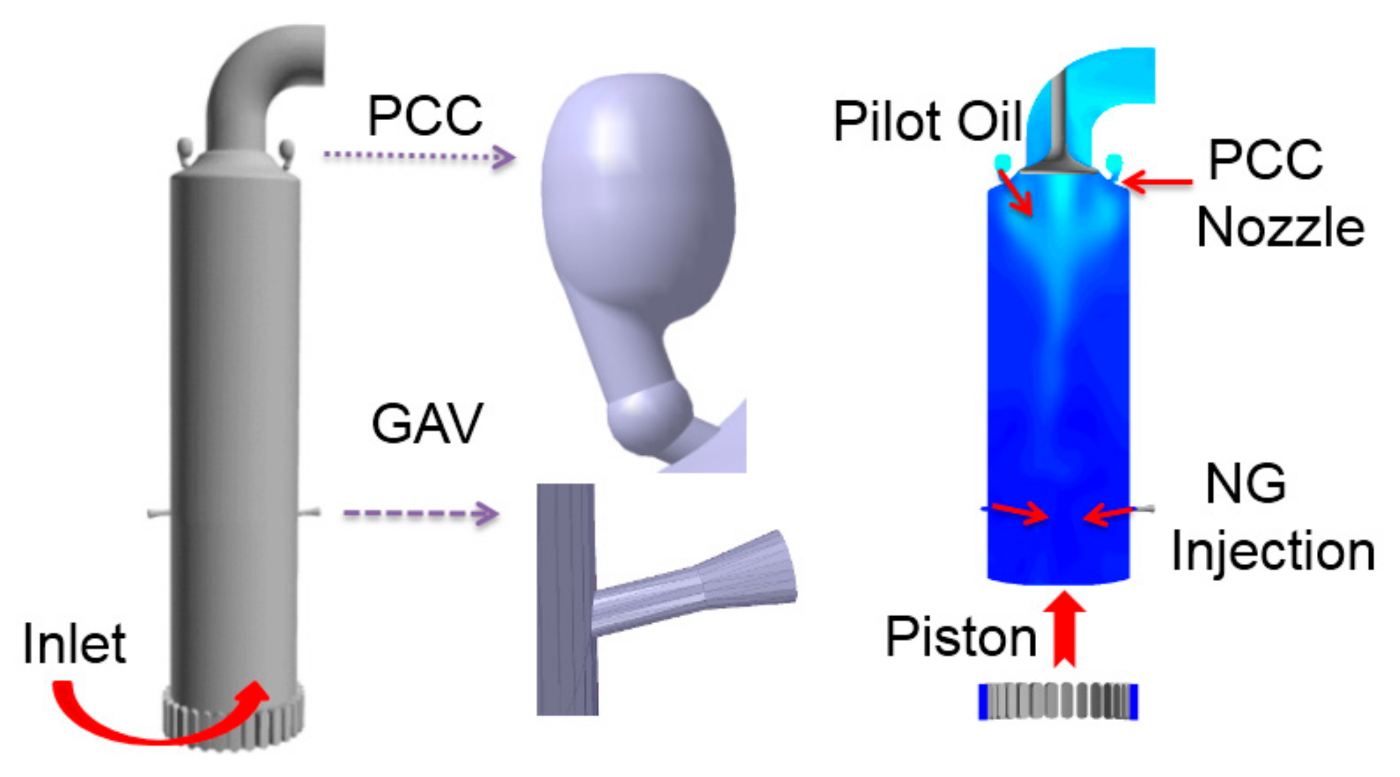
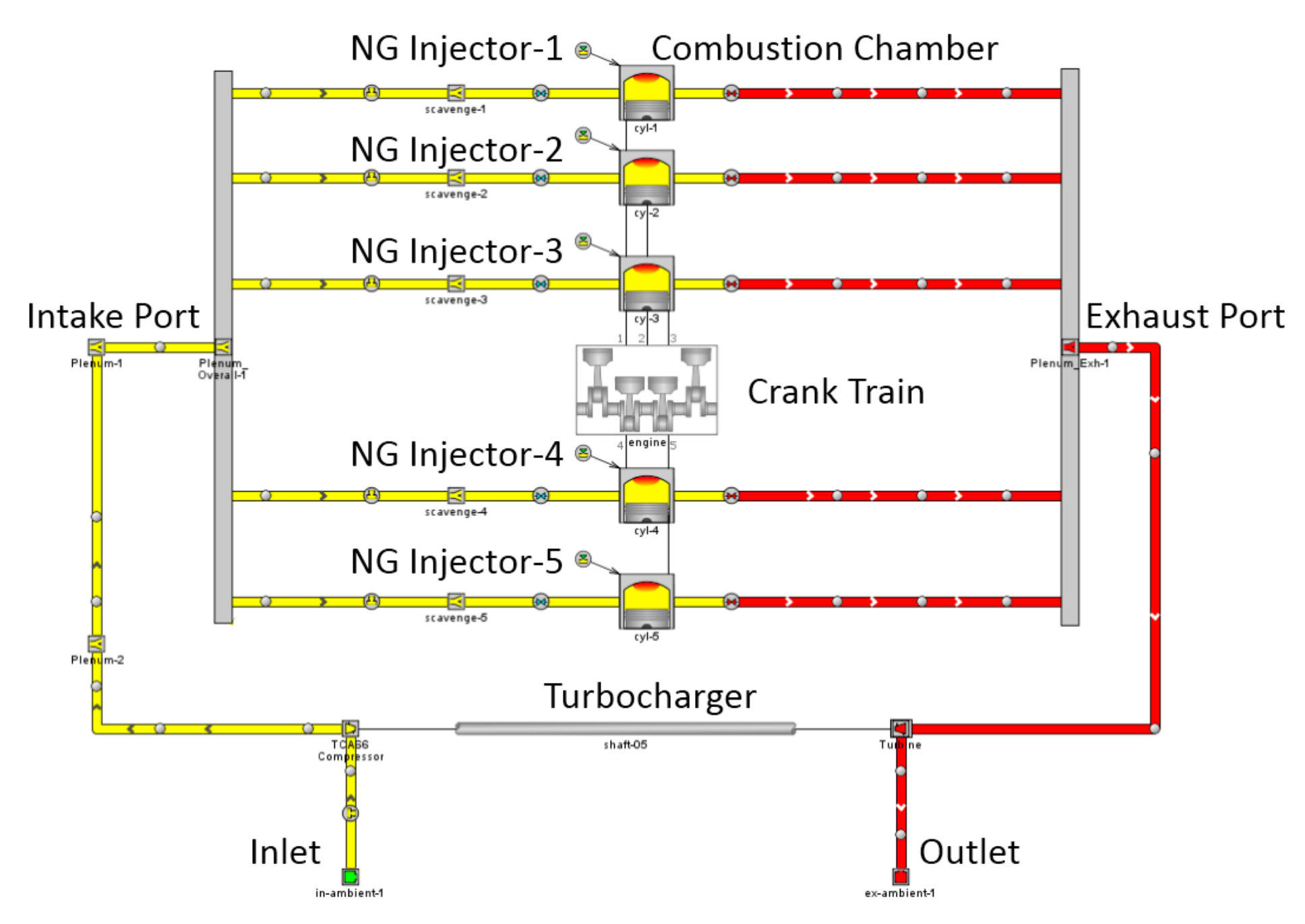
2. Model Description
2.1. LP-DF Engine Basic Parameters
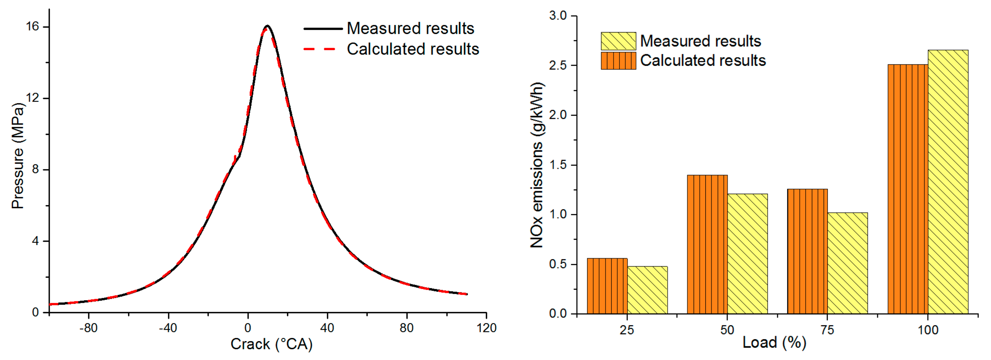
2.2. CFD Model Verification
3. Results and Discussion
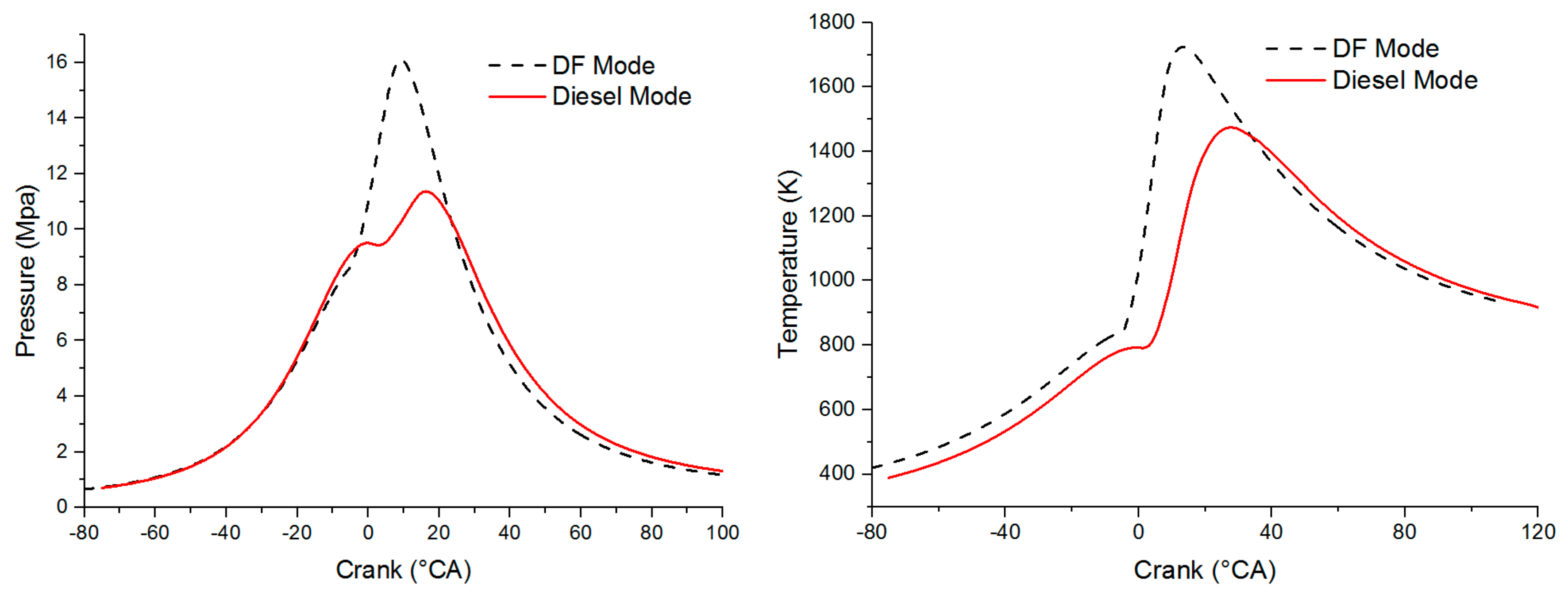
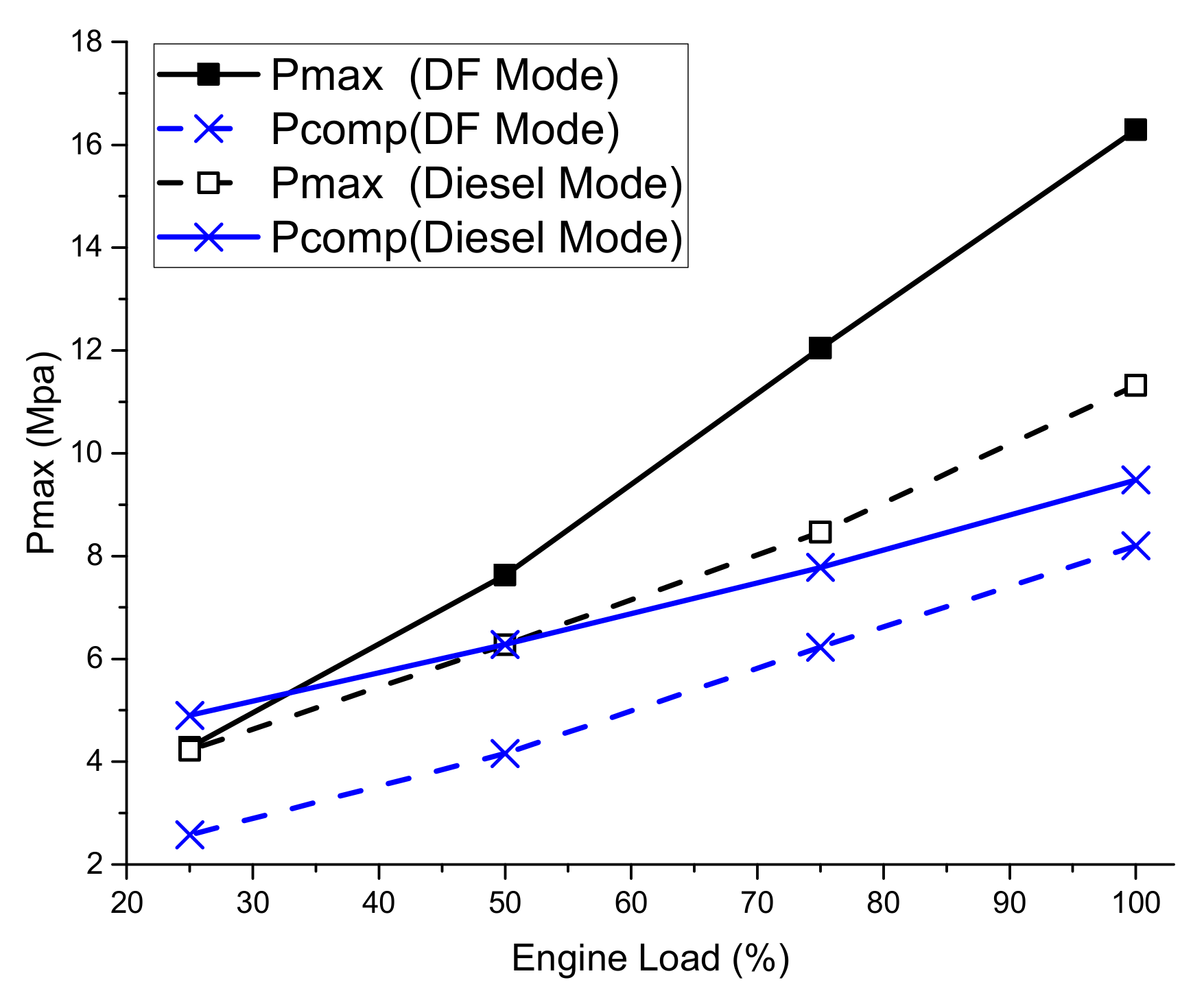
3.1. Performance Characteristics of A Marine LP-DF Engine
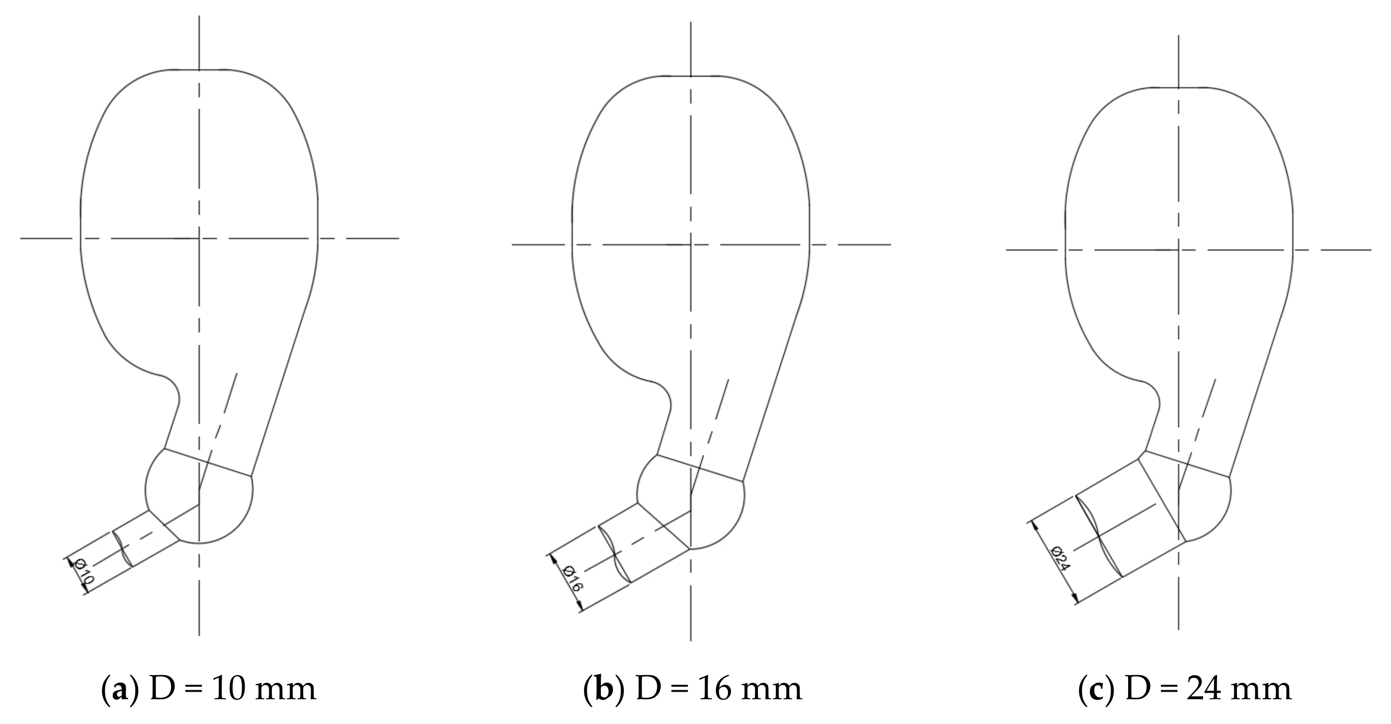
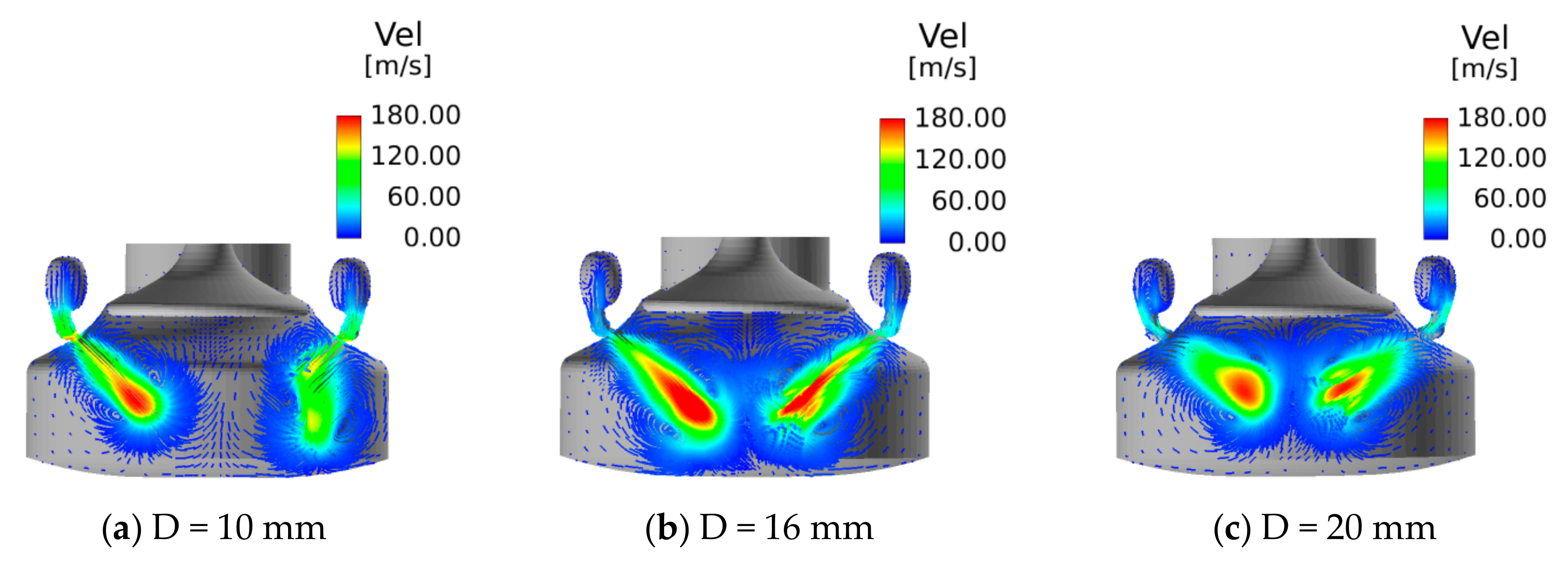
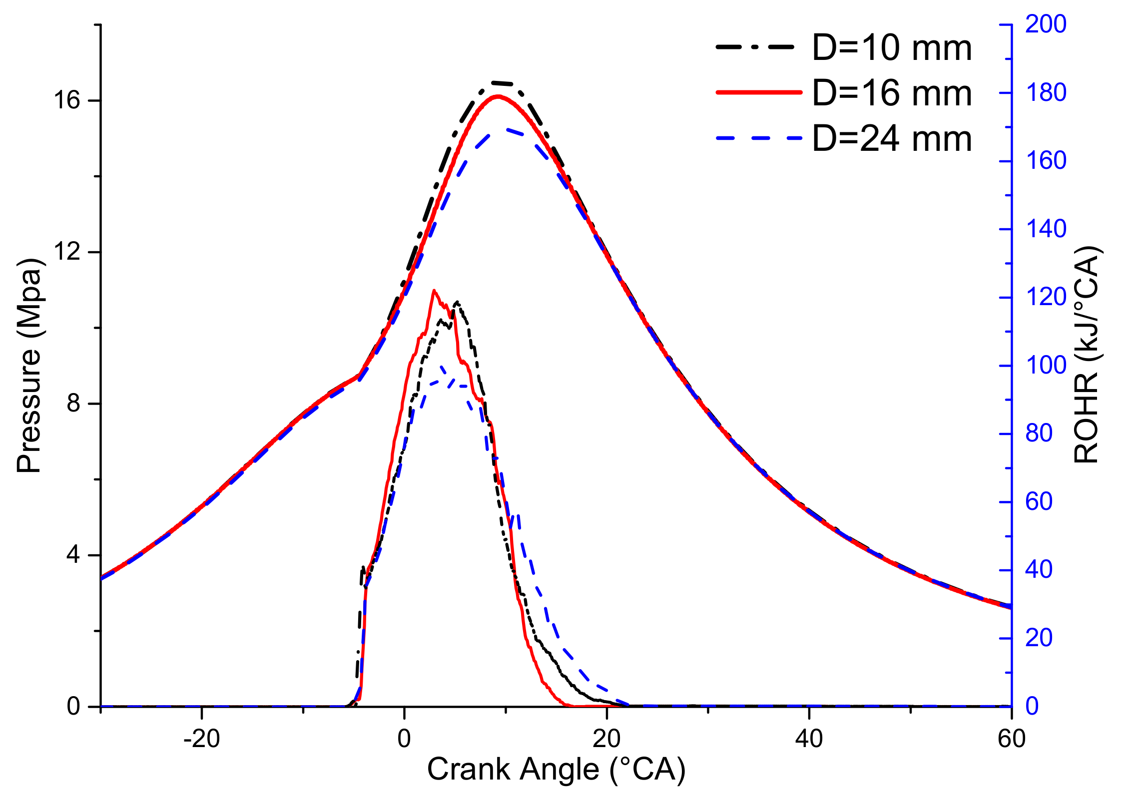
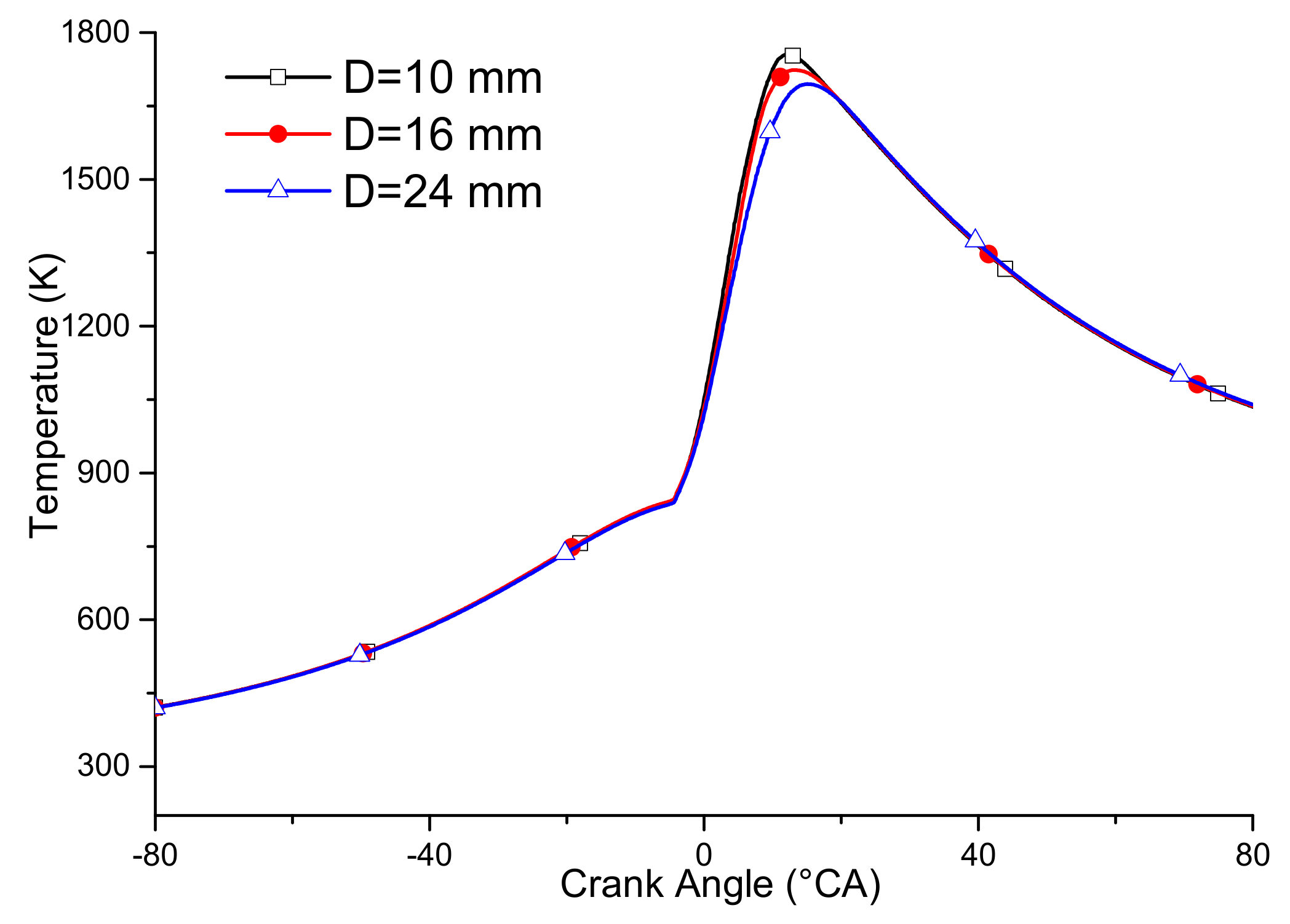
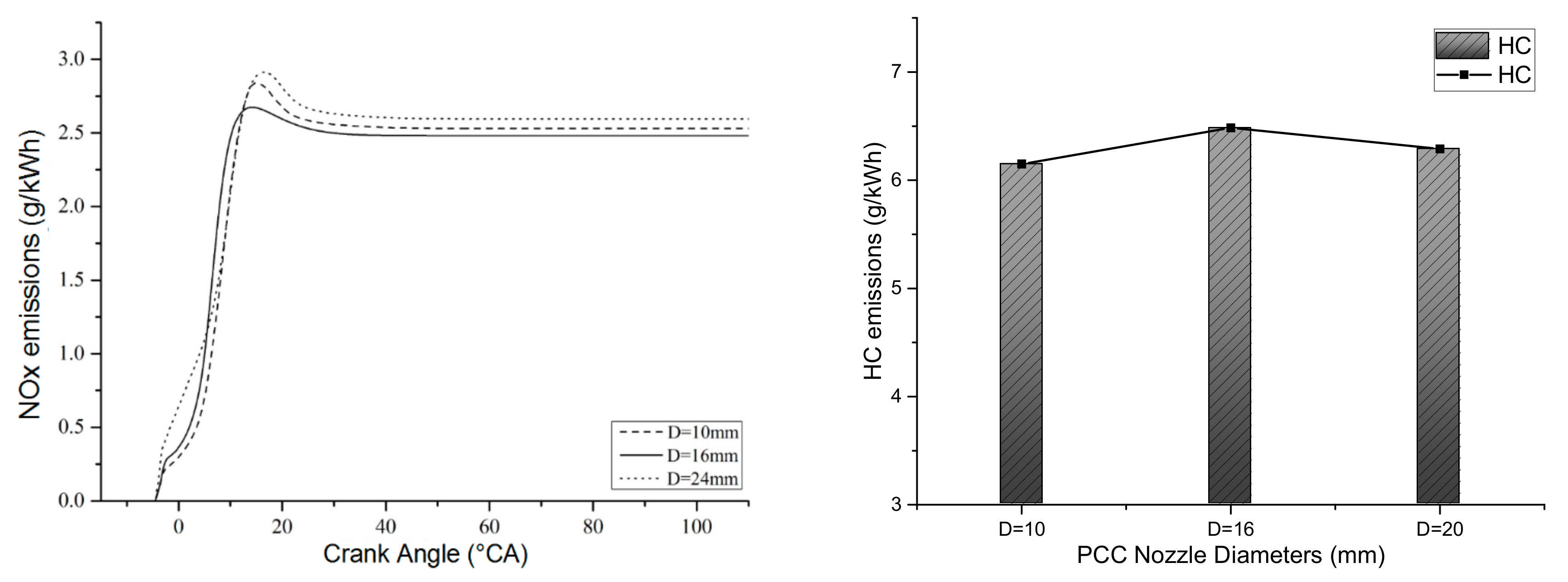
3.2. The Effect of PCC Nozzle Diameter
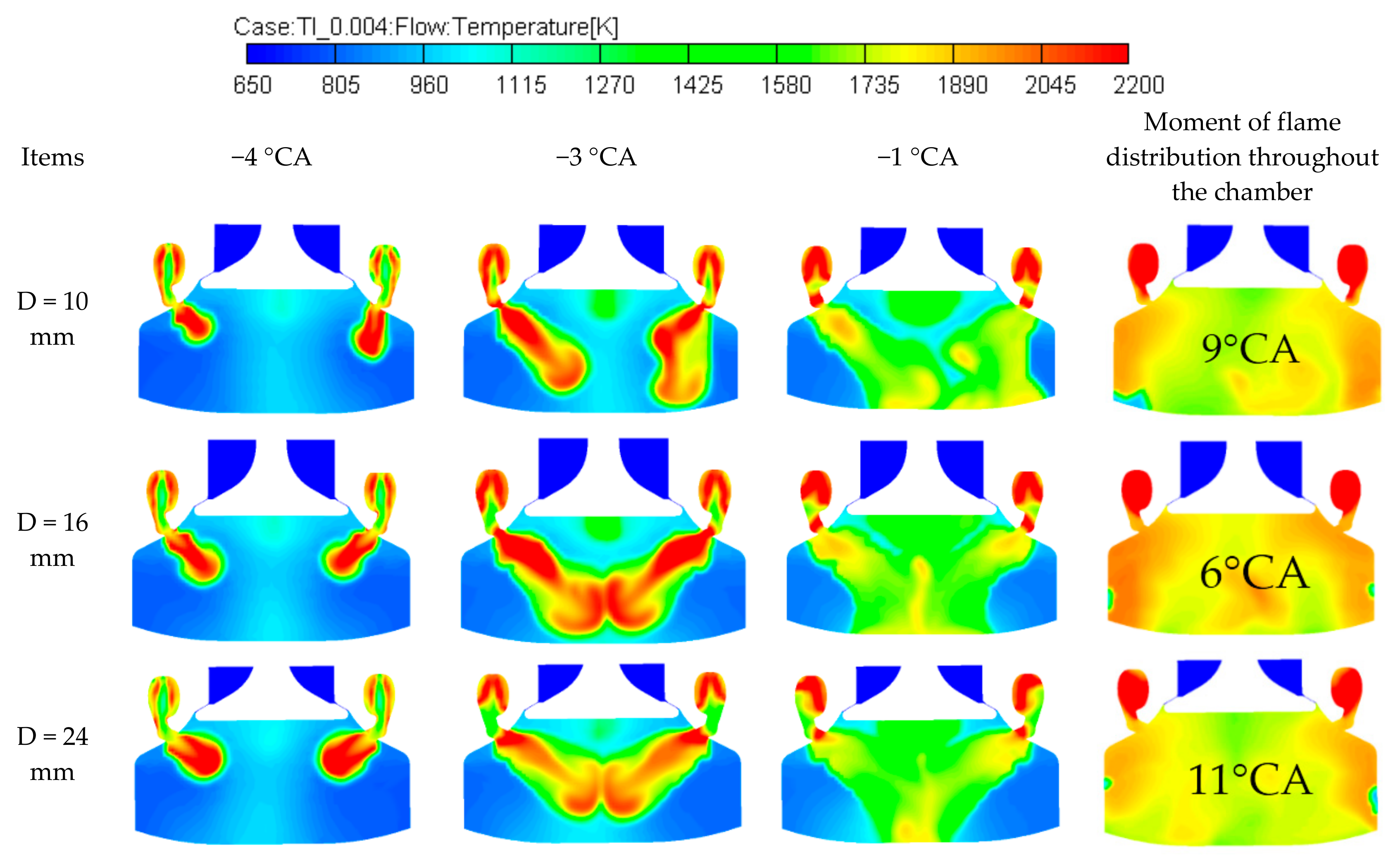
3.2.1. Influence on Combustion
3.2.2. Influence on Performance
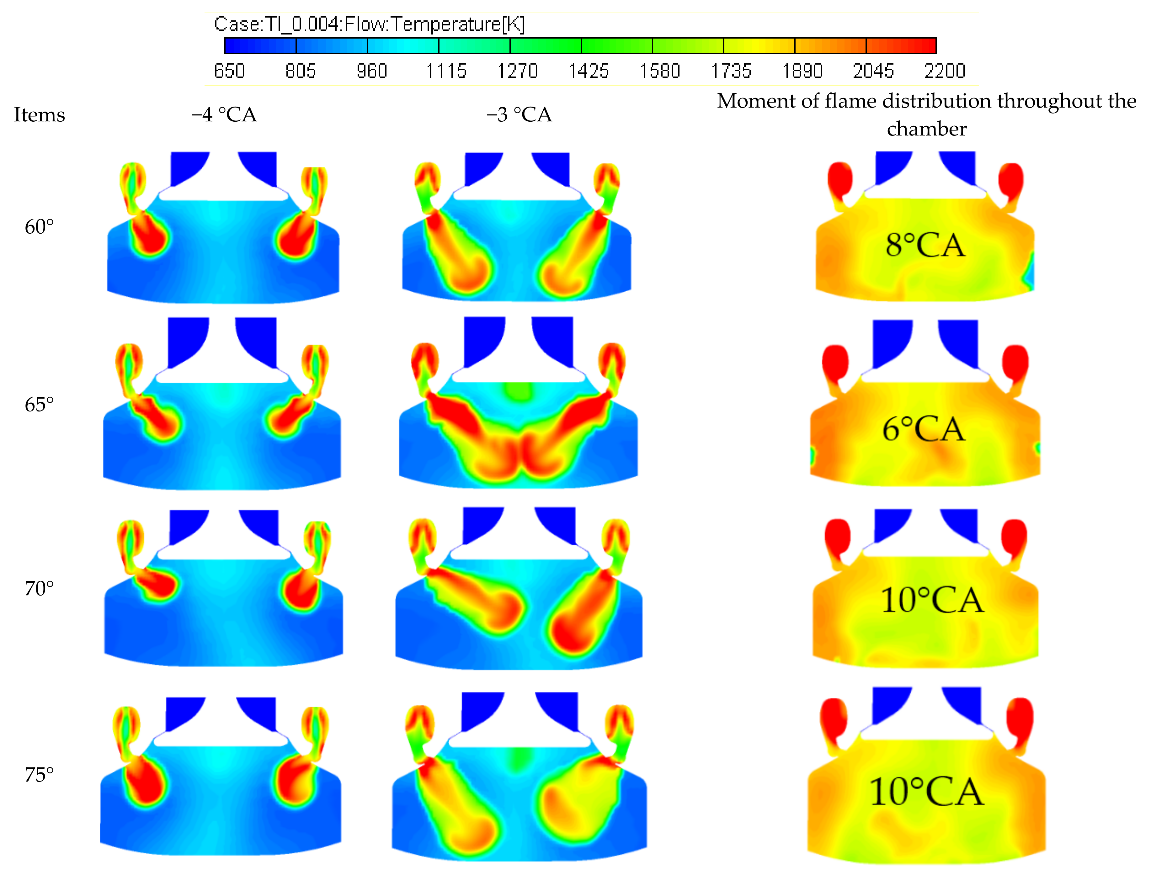
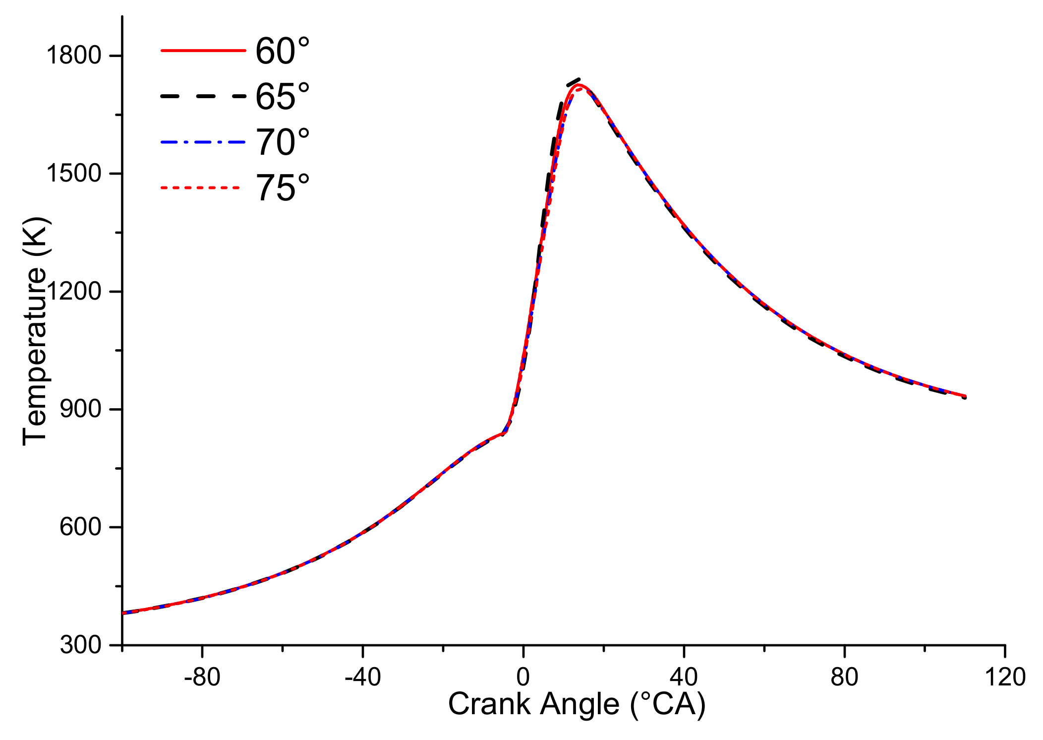
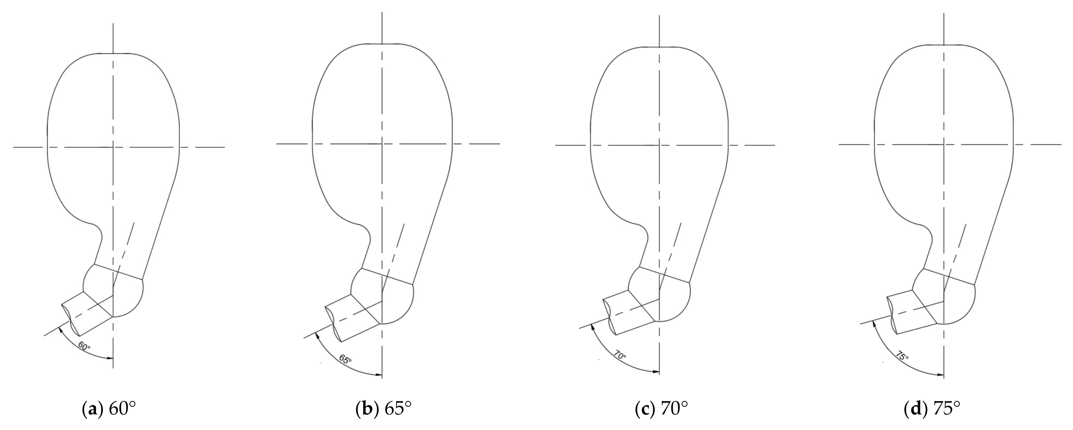
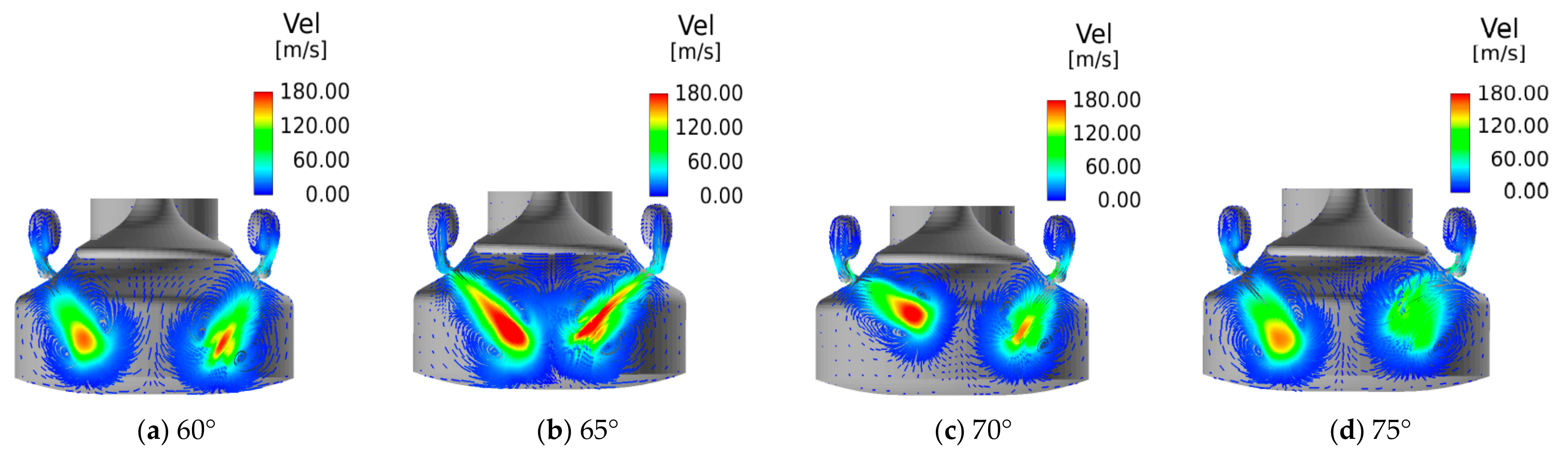
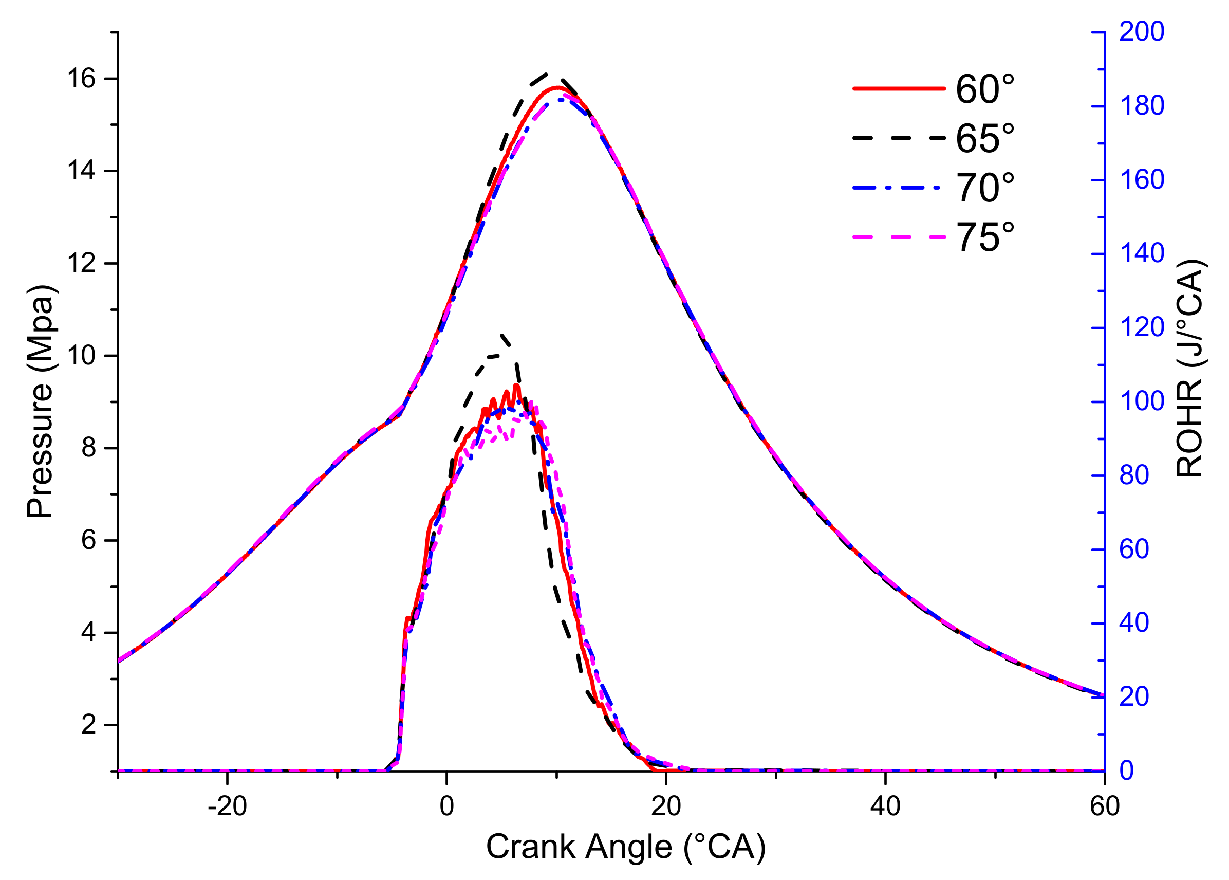
3.3. The Effect of PCC Nozzle Angle
3.3.1. Influence on Combustion
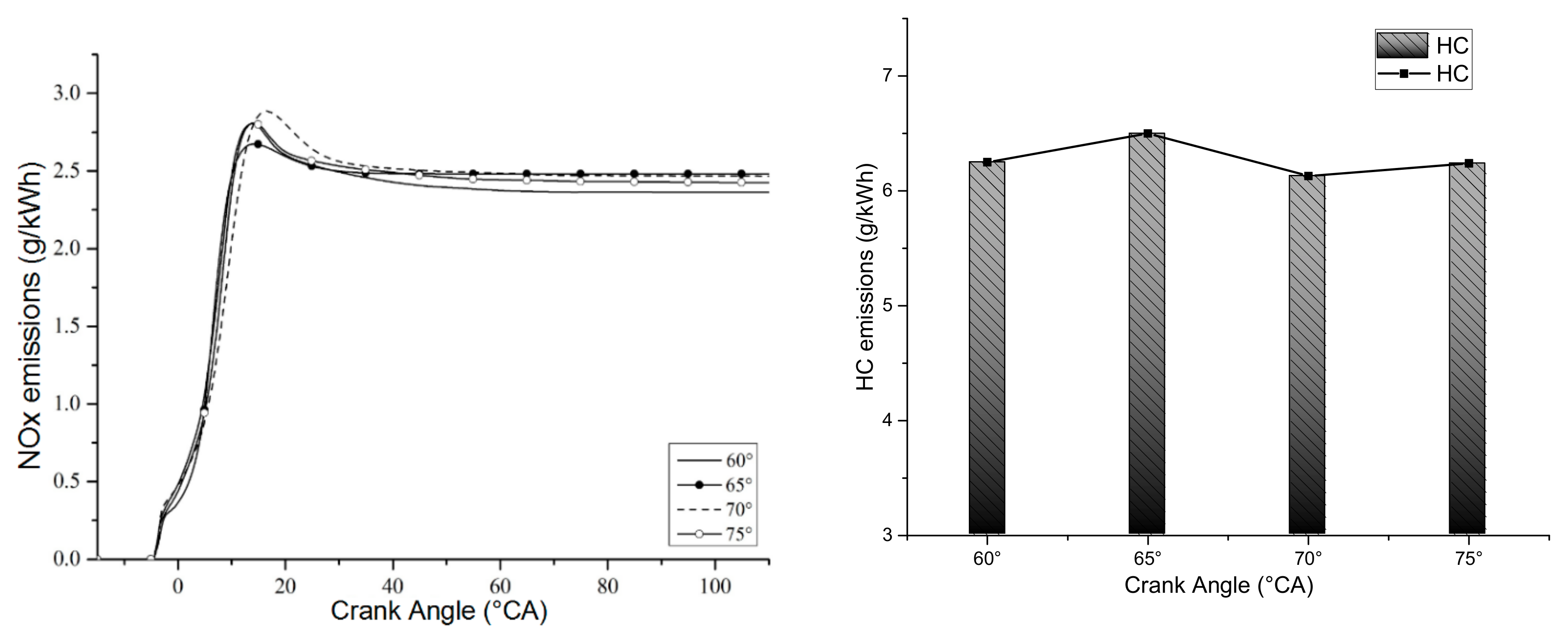
3.3.2. Influence on Performance
4. Conclusions
- (1)
- The pre-combustion chamber effectively organized the airflow in the cylinder and increased the flame propagation speed to achieve efficient lean combustion. The diameter of the PCC nozzle affected the propagation of the flame in the combustion chamber. Suitable PCC nozzle diameters helped to improve the flame propagation stability and engine performance and reduce emissions.
- (2)
- The angle of the PCC nozzle affected the direction of the flame propagation, which affected the flame propagation speed and thus the occurrence of knocking. Optimizing the angle of the PCC nozzle was beneficial to the organization of the in-cylinder combustion and helped to increase the flame propagation speed.
- (3)
- The 3D CFD simulation could be a powerful tool for LP-DF engine design. Future studies could include other aspects such as the PCC volume ratio, the PCC nozzle length, and the variable exhaust valve timing.
Author Contributions
Funding
Conflicts of Interest
Abbreviations
| IMO | International Maritime Organization |
| ECAs | Emission Control Areas |
| NOx | Nitrogen Oxides |
| SOx | Sulfur Oxides |
| CO | Carbon Monoxide |
| PM | Particulate Matter |
| HFO | Heavy Fuel Oil |
| LFO | Light Fuel Oil |
| LP-DF | Low-Pressure Dual-Fuel |
| HC | Hydrocarbon |
| ISO | International Organization for Standardization |
| CFD | Computational Fluid Dynamics |
| 1D | One-Dimensional |
| 3D | Three-Dimensional |
| BSPC | Brake Specific Pilot Fuel Consumption |
| BSGC | Brake Specific Gas Consumption |
| CAD | Computer Aided Design |
| PCC | Pre-Combustion Chamber |
| MCC | Main Combustion Chamber |
| GAV | Gas Admission Valve |
| λ | Air-Fuel Ratio |
| ROHR | Rate of Heat Release |
| TDC | Top Dead Center |
| °CA | Crank Angle Degree |
| bTDC | Before Top Dead Center |
| aTDC | After Top Dead Center |
References
- Christen, C.; Brand, D. IMO Tier III: Gas and Dual Fuel Engines as a Clean and Efficient Solution. In Proceedings of the CIMAC Congress, Shanghai, China, 13–17 May 2013; p. 187. [Google Scholar]
- Mehdi, G.; Zhou, S.; Zhu, Y.; Shah, A.H.; Chand, K. Numerical Investigation of SCR Mixer Design Optimization for Improved Performance. Processes 2019, 7, 168. [Google Scholar] [CrossRef]
- Kronholm, M. Demanding icebreaking LNG-powered icebreaking features the industry’s most advanced technology. In Proceedings of the CIMAC Congress, Helsinki, Finland, 6–10 June 2016; p. 226. [Google Scholar]
- Ahmed, S.A.; Zhou, S.; Zhu, Y.; Feng, Y.; Malik, A.; Ahmad, N. Influence of Injection Timing on Performance and Exhaust Emission of CI Engine Fuelled with Butanol-Diesel Using a 1D GT-Power Model. Processes 2019, 6, 299. [Google Scholar] [CrossRef]
- Kezirian, M.T.; Phoenix, S.L. Natural Gas Hydrate as a Storage Mechanism for Safe, Sustainable and Economical Production from Offshore Petroleum Reserves. Energies 2017, 10, 828. [Google Scholar] [CrossRef]
- Youfeng, L.; Liangjun, X. Development of low-fuel consumption and low-emission locomotive engine. In Proceedings of the CIMAC Congress, Vancouver, BC, Canada, 10–14 June 2019; p. 51. [Google Scholar]
- Xiang, L.; Song, E.; Ding, Y. A Two-Zone Combustion Model for Knocking Prediction of Marine Natural Gas SI Engines. Energies 2018, 11, 561. [Google Scholar] [CrossRef]
- Tozzi, L.; Emmanuella, S.; Greg, B. Novel Pre-Combustion Chamber Technology for Large Bore Natural Gas Engines. In Proceedings of the CIMAC Congress, Helsinki, Finland, 6–10 June 2016; p. 259. [Google Scholar]
- Mohr, H.; Baufeld, T. Improvement of Dual Fuel Engine Technology for Current and Future Applications. In Proceedings of the CIMAC Congress, Shanghai, China, 13–17 May 2013; p. 412. [Google Scholar]
- Delneri, D.; Sirch, G. Enhanced Flexibility in Gas Engine Operation for Marine and Power Generation Demanding Applications. In Proceedings of the CIMAC Congress, Vancouver, BC, Canada, 10–14 June 2019; p. 93. [Google Scholar]
- Ilari, K.; Ulf, A.; Grant, G. Product Technology Development for Increased Customer Benefits. In Proceedings of the CIMAC Congress, Helsinki, Finland, 6–10 June 2016; p. 285. [Google Scholar]
- Yasueda, S.; Kuboyama, T.; Matsumura, M.; Moriyoshi, Y.; Doyen, V.; Martin, J.B. The examination on the main contributing factors of lube oil pre-ignition. In Proceedings of the CIMAC Congress, Helsinki, Finland, 6–10 June 2016; p. 147. [Google Scholar]
- Zheng, X.; Yang, J. An Investigation into the Gas-Mode Start Strategies for a Marine Medium-Speed Micro-Pilot-Ignition Dual-Fuel Engine. In Proceedings of the CIMAC Congress, Vancouver, BC, Canada, 10–14 June 2019; p. 71. [Google Scholar]
- Alla, G.H.A.; Soliman, H.A.; Badr, O.A. Effect of injection timing on the performance of diesel engine. Energy Convers. Manag. 2002, 43, 269–277. [Google Scholar] [CrossRef]
- Papagiannakis, R.G.; Rakopoulos, C.D.; Hountalas, D.T.; Rakopoulos, D.C. Emission characteristics of high speed, dual fuel, compression ignition engine operating in a wide range of natural gas/diesel fuel proportions. Fuel 2010, 89, 1397–1406. [Google Scholar] [CrossRef]
- Hirose, T.; Masuda, Y. Technical Challenge for the 2-Stroke Premixed Combustion Gas Engine. Pre-ignition Behavior and Overcoming Technique. In Proceedings of the CIMAC Congress, Shanghai, China, 13–17 May 2013; p. 185. [Google Scholar]
- Alla, G.A.; Soliman, O.A. Effect of pilot fuel quantity on the performance of a dual fuel engine. Energy Convers. Manag. 2000, 41, 559–572. [Google Scholar] [CrossRef]
- Duan, X.; Liu, J.; Yao, J. Performance, combustion and knock assessment of a high compression ratio and lean-burn heavy-duty spark-ignition engine fuelled with n-butane and liquefied methane gas blend. Energy 2018, 158, 256–268. [Google Scholar] [CrossRef]
- Guo, H.; Song, Z. Study on the Influence of Prechamber Structure on the Knock of a Marine Low-Speed Dual-fuel Engine. In Proceedings of the CIMAC Congress, Vancouver, BC, Canada, 10–14 June 2019; p. 50. [Google Scholar]
- Hokimoto, S.; Kuboyama, T. Combustion analysis in a natural gas engine with pre-chamber by three-dimensional numerical simulation. Trans. Jpn. Soc. Mech. Eng. 2015, 47, 28–37. [Google Scholar]
- Yousefi, A.; Birouk, M. Investigation of natural gas energy fraction and injection timing on the performance and emissions of a dual-fuel engine with pre-combustion chamber under low engine load. Appl. Energy 2017, 189, 492–505. [Google Scholar] [CrossRef]
- Cernik, F.; Macek, J.; Dahnz, C.; Hensel, S. Dual Fuel Combustion Model for a Large Low-Speed 2-Stroke Engine; SAE Technical Paper: Prague, Czech Republic, 2016. [Google Scholar]
- Maghbouli, A.; Saray, R.K.; Shafee, S. Numerical study of combustion and emission characteristics of dual-fuel engines using 3D-CFD models coupled with chemical kinetics. Fuel 2013, 106, 98–105. [Google Scholar] [CrossRef]
- Liu, T.; Gui, Y. Pre-Combustion Chamber Design Scheme Analysis for a Typical Marine Low Speed Duel Fuel Engine. In Proceedings of the CIMAC Congress, Vancouver, BC, Canada, 10–14 June 2019; p. 100. [Google Scholar]
- Maghbouli, A.; Shafee, S.K.; Saray, R.; Yang, W. A Multi-Dimensional CFD-Chemical Kinetics Approach in Detection and Reduction of Knocking Combustion in Diesel-Natural Gas Dual-Fuel Engines Using Local Heat Release Analysis. SAE Int. J. Engines 2013, 6, 777–787. [Google Scholar] [CrossRef]
- Jha, P.R.; Srinivasan, K.K.; Krishnan, S.R. Influence of Swirl Ratio on Diesel-Methane Dual Fuel Combustion: A CFD Investigation. In Proceedings of the ASME 2017 Internal Combustion Engine Division Fall Technical Conference, Seattle, WA, USA, 15–18 October 2017. [Google Scholar]
- Nylund, I.; Ott, M. Development of a Dual Fuel Technology for Slow-speed Engines. In Proceedings of the CIMAC Congress, Shanghai, China, 13–17 May 2013; p. 284. [Google Scholar]
- Christoforos, M.; Gerasimos, T. Numerical investigation of a premixed combustion large marine two-stroke dual fuel engine for optimising engine settings via parametric runs. Energy Convers. Manag. 2018, 160, 48–59. [Google Scholar]
- Takahiro, K.; Takahide, A. Study on Mixture Formation Process in Two Stroke Low Speed Premixed Gas Fueled Engine. In Proceedings of the CIMAC Congress, Helsinki, Finland, 6–10 June 2016; p. 207. [Google Scholar]
- Zhou, S.; Gao, R.F.; Feng, Y.M. Evaluation of Miller cycle and fuel injection direction strategies for low NOx emission in marine two-stroke engine. Int. J. Hydrog. Energy 2017, 42, 20351–20360. [Google Scholar] [CrossRef]
- Ott, M.; Nylund, I. The 2-stroke Low-Pressure Dual-Fuel Technology: From Concept to Reality. In Proceedings of the CIMAC Congress, Helsinki, Finland, 6–10 June 2016; p. 233. [Google Scholar]
- Flot, P.; MESLATI, A.; Digneton, M. Improving Efficiency and Emissions of Otto Gas Engines, by Continuously Monitoring Fuel Gas Quality. In Proceedings of the CIMAC Congress, Vancouver, BC, Canada, 10–14 June 2019; p. 26. [Google Scholar]


| Parameter | Value |
|---|---|
| Bore | 500 mm |
| Stroke | 2050 mm |
| Cylinder Number | 5–8 |
| Speed | 124 r/min |
| Power | 8640 kW |
| Compression Ratio | 12 |
| Brake Specific Pilot Fuel Consumption (BSPC) (DF Mode) * | 1.8 g/kWh |
| Brake Specific Gas Consumption (BSGC) (DF Mode) * | 142.7 g/kWh |
© 2019 by the authors. Licensee MDPI, Basel, Switzerland. This article is an open access article distributed under the terms and conditions of the Creative Commons Attribution (CC BY) license (http://creativecommons.org/licenses/by/4.0/).
Share and Cite
Guo, H.; Zhou, S.; Shreka, M.; Feng, Y. Effect of Pre-Combustion Chamber Nozzle Parameters on the Performance of a Marine 2-Stroke Dual Fuel Engine. Processes 2019, 7, 876. https://doi.org/10.3390/pr7120876
Guo H, Zhou S, Shreka M, Feng Y. Effect of Pre-Combustion Chamber Nozzle Parameters on the Performance of a Marine 2-Stroke Dual Fuel Engine. Processes. 2019; 7(12):876. https://doi.org/10.3390/pr7120876
Chicago/Turabian StyleGuo, Hao, Song Zhou, Majed Shreka, and Yongming Feng. 2019. "Effect of Pre-Combustion Chamber Nozzle Parameters on the Performance of a Marine 2-Stroke Dual Fuel Engine" Processes 7, no. 12: 876. https://doi.org/10.3390/pr7120876
APA StyleGuo, H., Zhou, S., Shreka, M., & Feng, Y. (2019). Effect of Pre-Combustion Chamber Nozzle Parameters on the Performance of a Marine 2-Stroke Dual Fuel Engine. Processes, 7(12), 876. https://doi.org/10.3390/pr7120876