1. Introduction
One of the types of tribological wear is fretting wear [
1,
2]. It includes a group of phenomena related to micro-abrasive wear in loaded and nominally immovable joints, which can be mechanical, thermal, chemical, or electrical. Its main consequence is a drastic decrease of durability and shortened operational reliability of the devices. The wear of the surface layers of elements being in contact with each other takes place as a result of oscillational micro-shifts of the contacting surfaces [
3,
4,
5,
6,
7]. Fretting can be accompanied by four basic mechanisms: adhesion, fatigue, abrasion, and corrosion. Adhesive damage to the surface and the formation of fatigue cracks causes the creation of wear particles, followed by their oxidation and hardening [
8,
9].
Linked, nominally immovable surfaces are in contact only through the roughness peaks being a consequence of the roughness. Therefore, the actual contact surface is only a small fraction of the nominal surface. In the existing roughness contacts, we can distinguish between four adhesion areas, which undergo elastic deformations, as well as areas of micro-slips. A consequence of the contact surfaces’ small shifts of in respect of each other as a result of the applied external loads, which are cyclic in character, can be a contact load exerted by the axial force and the tangential force. Fretting wear has also been observed to occur as a result of free vibration of the construction. Respectively to different states, Neyman [
8] differs: fretting wear as a loss of mass and volume in the surface layer, fretting corrosion where oxidation of the surface layer dominates and fretting fatigue that may occur during variable load. Respectively to the mentioned different states of loads and operation, we distinguish between “fretting fatigue” and “fretting wear” [
10]. The presence of areas of adhesion and micro-slips is strictly connected with the occurrence of two different wear mechanisms in them. The adhesion areas undergo cracking in the mode of contact fatigue, whereas the micro-slip areas are subjected to adhesion wear. In both cases, we observe the formation of wear products, which remain in abrasive contact. If they exhibit high hardness, they work as an abradant, accelerating the process of wear, especially in its last, catastrophic phase. Fretting almost always occurs with chemical changes of the surface except in exceptional cases of high vacuum, inert atmospheres, or precious metal contact. In active environment, where fretting corrosion takes place, wear appears sooner and is much more intensive [
6,
11,
12,
13,
14,
15]. Fretting corrosion is formed in couples working in a corrosive environment. The tensions cause an increase of the surface energy and chemical reactivity. Also, in the case of fretting corrosion, products of wear are created, which are usually metal oxides [
16]. Those can be the oxides removed from the surface or formed as a result of oxidation of particles of the abraded metal. These products work as an abradant; they are refined and hardened and their amount increases until the surface is separated with a layer of oxide molecules and the wear conditions stabilize. In the contact area, we also observe processes of materials’ transfer with intensive oxidation [
8]. The intensity of fretting depends on the type and value of the forcing applied to the joint, the value of the stresses with which it operates, and the aggressiveness of the environment [
9].
Cases of destruction through fretting have been established not only in elements of machines and constructions but also in orthopedic implants, as well as prosthetic, orthodontic, and artificial heart elements [
11,
13,
16,
17,
18,
19,
20,
21,
22,
23]. The fretting phenomenon refers to most biomaterials, both metallic ones and polymers and ceramics [
24,
25,
26,
27]. Fretting is especially important in the environment of the oral cavity. There are known cases of wear products of orthodontic elements (mainly ligatures) adsorbing onto the dental plaque, causing discolorations. Although weight of particles is marginal, the total releasing area is more of a concern due to amount and volume of molecules. The intensity of the process depends not only on the element but mainly on the size of contacting surfaces. A part of them is transferred into the digestive system, from which, in the form of oxides and metal ions (iron, chromium, nickel), enter the body, working toxically [
28,
29,
30]. The effect of the environment is crucial for the processes of fretting and corrosive wear. Its aggressiveness is largely affected by the chemically active substances, especially chlorine, sulfur, oxygen, and phosphorus compounds [
11,
31]. The human saliva is necessary in the oral cavity; it has a series of protective and supplementary functions, including the lubrication function, and at the same time, it has a big influence on the processes of corrosive and fretting wear [
12,
31,
32,
33,
34,
35,
36,
37]. Because of adverse effects, fretting should be taken into consideration from clinical standpoint.
The non-precious alloys most commonly used in the preparation of prosthetic and orthodontic elements containing cobalt, chromium, nickel, and molybdenum demonstrate a relatively low corrosion resistance compared to precious metal alloys, which helps the elements being part of their compositions enter the body [
38,
39]. In order to increase their biological tolerance, various types of modification of the surface layer of the elements made of these alloys are applied, which makes it possible to obtain biocompatibility. It is worth noting that many of those layers enable an improvement of the wear resistance. Also, this resistance has been established to be higher compared to uncoated alloys [
12,
40]. A special focus should be put on titanium carbides and nitrides coatings. This results mainly from their high durability, corrosion resistance, and biomcompatibility [
41,
42,
43,
44,
45].
The aim of the study was to examine the fretting wear resistance of prosthetic and orthodontic alloy Ni-Cr-Mo samples coated with Ti(C, N) layers and to compare them with samples without any coating.
2. Test Material and Methods
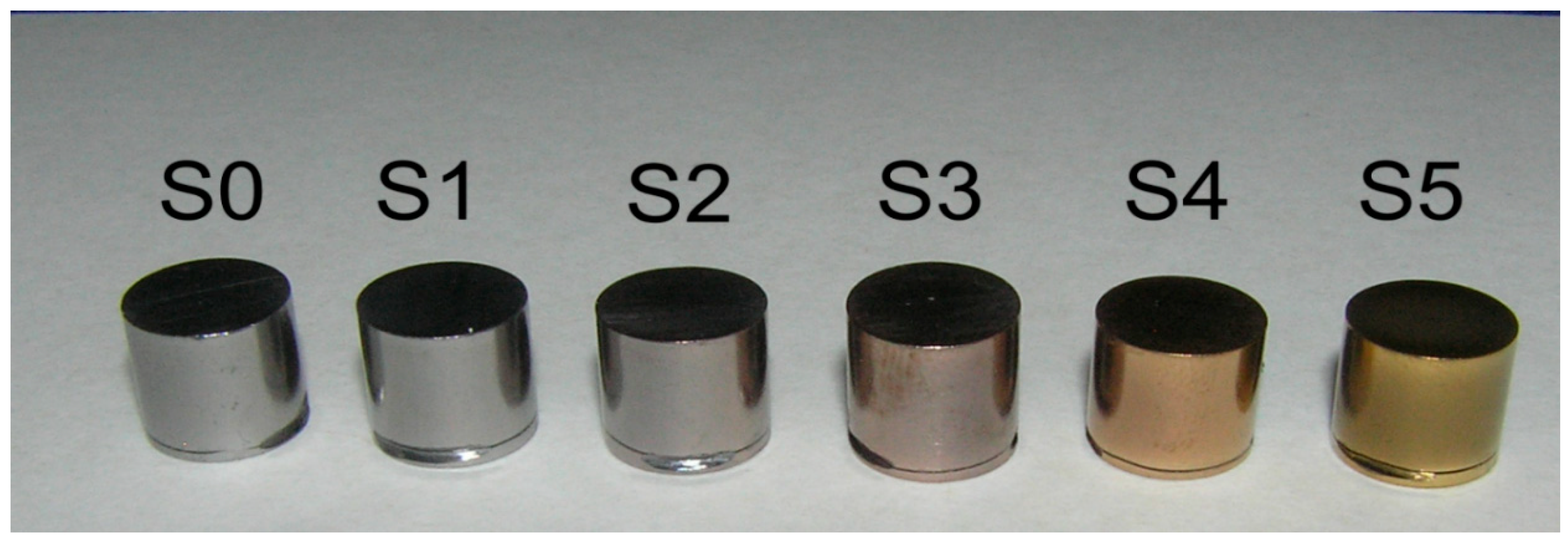
The test material were disks made of the Ni-Cr alloy, 8 mm in diameter and 10 mm high (
Figure 1). The initial composition of the alloy determined by the X-ray fluorescence analysis technique with the use of a spectrometer SRS300 by SIEMENS is given in
Table 1. The disks were divided into six groups. First group without coating (S0), others (S1–S5) differed in the amount of C and N in the deposited Ti(C, N) coating (
Table 2).
Layers were deposited using magnetron sputtering method. In order to improve adherence of Ti(C, N) layers, first adhesive sublayer of pure titanium was deposited during 120 s with argon pressure equal to 0.24 Pa and with the following work parameters of magnetron: 3 kW/approximately 4.5 A. After two minutes reactive gas was slowly introduced: nitrogen, acetylene, or their mixture. Deposition time of appropriate layer was the same for all processes and equal to 7200 s. Polarization with constant voltage during deposition was −100 V. Pressure of the process was 0.27 Pa in each case. The reactive gases and their flow is presented in
Table 3. These were the only variables of the processes.
Prepared samples were examined. Layers thickness was measured and ranged from 1.25 μm to 1.62 μm, which was thoroughly described in previous article [
46]. Film adhesion was also tested, in preceding article [
45], according to VDI 3198 norm. The test consists in comparing the obtained imprints with the standards and determine the degree of delamination of the coating. In the impressions obtained, no cracking of the coating from the substrate was observed. The received results should be classified in the HF1 standard, with a very low density crack. Previous studies measured also the hardness and modulus of elasticity using the nanoindentation method [
45]. The results for hardness ranged from 20 to 34 GPa, whereas the modulus ranged from 272 GPa to 382 GPa. Then, samples underwent fretting wear resistance tests under fretting conditions. In order to eliminate the impurities, before each test, the samples were placed in a sonifier and rinsed in ethanol for 10 min. The experiments were performed under the conditions of dry friction on a special fretting tester designed and made at the Faculty of Mechanical Engineering of Bialystok University of Technology, Poland. The schematics of the fretting test device have been shown in
Figure 2.
The friction processes were realized with a small amplitude of the order of 100 μm, at the frequency of 0.8 Hz, with averaged unit load: 5, 10, and 15 N and for the predetermined time of 15 min. For the load of 15 N, additional tests were performed for the times of: 30, 60, and 120 min (
Table 4).
The movable table of the device, on which the samples were mounted, was making a reversible movement. A counter-sample was pressed onto the surface of the disk, shaped like a truncated cone, whose contact surface diameter equaled 1.3 mm (
Figure 3). The counter-samples were made from the Co-Cr-Mo alloy.
After the fretting processes, the samples were subjected to microscopic observations with the use of a scanning electron microscope Hitachi S3000N and a laser scanning microscope LEXT OLS4000. The observations aimed to determine the character of the samples’ wear. Under the scanning microscope, beside the assessment of the wear character, analyses of the chemical composition in the friction area were conducted. To that end, an EDS detector (with energy dispersion) by Pioneer working with a microscope was used. The test results have been presented in
Figure 4,
Figure 5,
Figure 6,
Figure 7,
Figure 8,
Figure 9 and
Figure 10. The observations under a laser scanning microscope with the use of the 3D option made it possible to perform tests of surface roughness and friction track profiles, which enabled the determination of the wear depth on the particular samples, thus facilitating the assessment of the fretting resistance of the examined coatings. The results of the wear measurements have been included in
Table 5.
3. Test Results
SEM and EDS Tests
Microscopic observations in SEM and EDS were performed on all the samples and in each of them, all the friction tracks were examined. Exemplary images of all the tracks for sample S1 has been shown in
Figure 4.
On all the other samples with coatings, the friction tracks observed in SEM were analogical.
Figure 5 shows friction track images obtained with the maximal loads of samples S0 and S5.
We can see in the presented microscopic images that the surface damage was diversified, depending on the test parameters. In the case of a test with higher loads and longer times, abrasion of the coating took place and the base was revealed.
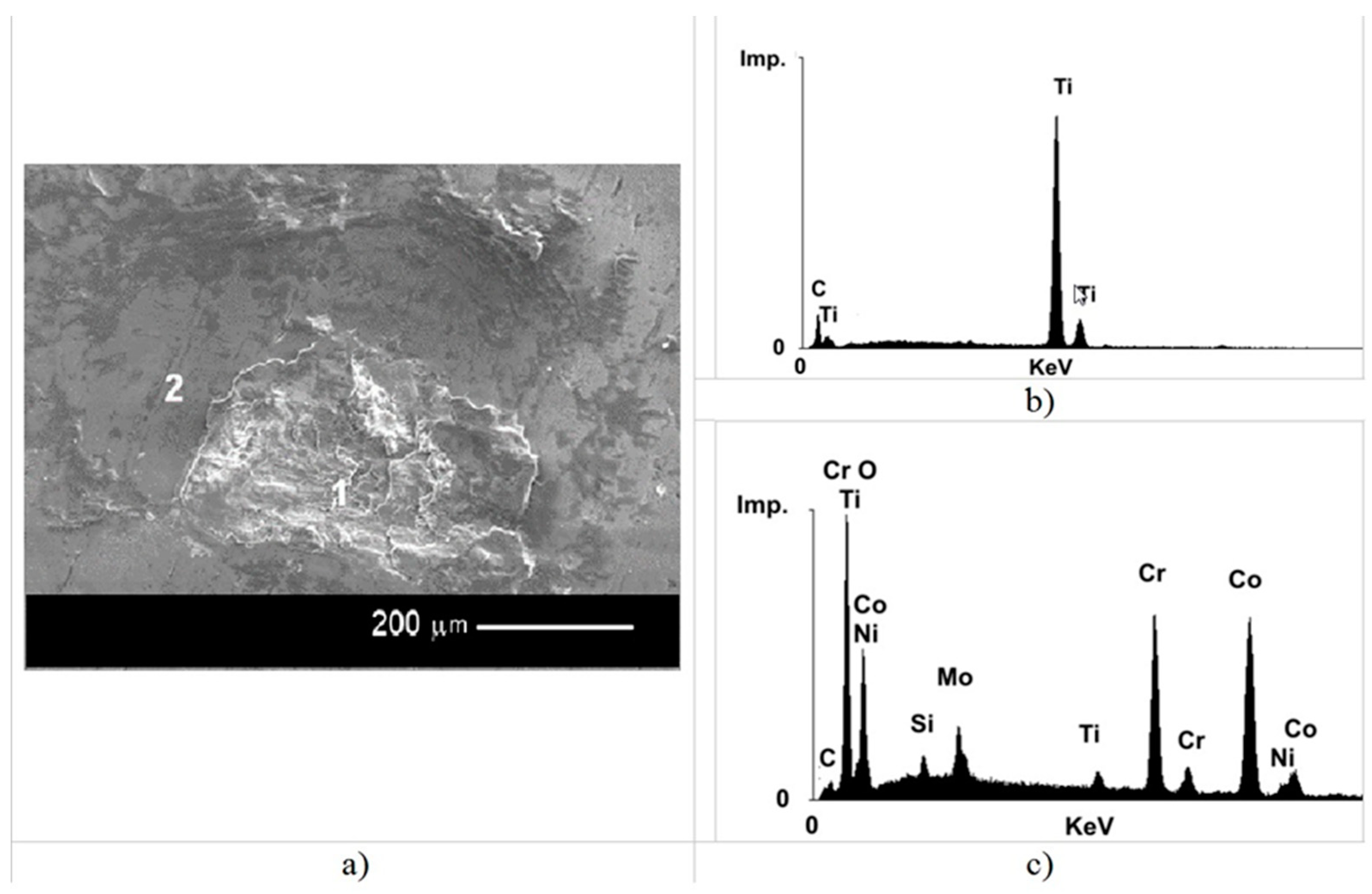
In order to confirm this fact, chemical composition analyses were performed in the micro-area of the fretting wear. Exemplary results of these analyses for samples S1 and S5 have been presented in
Figure 6 and
Figure 7.
As we can infer from the chemical composition analysis, in the examined micro-areas, after the abrasion of the TiC coating, the base was revealed. In the revealed area, the following elements are present: C, Ti, O, Cr, Co, and Ni. Their origins are different. Both nickel and chromium originate from the metallic base of the sample. Considering the ratio of the signal heights from chromium and nickel, it should be noted that the signal coming from chromium is significantly higher than suggested by the composition of the base alloy. The presence of cobalt proves a transfer, in the friction process, of the counter-sample material (Co-Cr-Mo alloy) into the friction area, which explains also the higher content of chromium in the examined area. The presence of titanium and carbon can be explained by the remains of the TiC coating-probably residues of the wear products. The presence of oxygen in the friction area proves the occurrence of oxidation processes during the friction. As a result, we probably observe fretting-corrosion rather than pure fretting.
Analogical results were obtained in the other samples (see
Figure 7). In sample S5, the presence of nickel and chromium in point 1, in the face of a strong signal from Ti, may prove such thinning of the TiN coating that we receive a signal from the base material. Similarly to the case of the TiC coating in this sample, after the base had been revealed, there was a transfer of the counter-sample material to the friction area, which has been shown in
Figure 7c,d. The presence of cobalt in point 3, with a relatively high signal from titanium and nitrogen, can be explained by the transfer of the counter-sample material onto the TiN coating.
The element distribution on the friction area is better presented by the surface element distribution maps, shown in
Figure 8 and
Figure 9 for selected samples.
The next stage of investigations consisted in determining the degree of the fretting wear. As the wear degree parameter the maximal depth on the friction track was assumed, determined by means of a laser scanning microscope. In order to compare the wear resistance of the particular coatings, only those friction tracks which had not revealed the base were selected. The depth of the tracks with a revealed base is not reliable, as the base (Ni-Cr-Mo alloy) wears off in a decisively different way than the coatings. In order to determine those friction tracks which reveal the base, distribution maps of the elements present in the coatings and the base for all the examined samples and friction tracks were created. An exemplary map for the friction track with a non-revealed base for sample S1 has been shown in
Figure 10, where, in the whole test area, we can see a uniform distribution of titanium and carbon. There are no visible areas with an elevated content of nickel or chromium. This proves that the base has not been revealed. It should be noted that no presence of cobalt is observed on the surface. Therefore, we can conclude that, for the TiC layer, with a short examination time, there is no transfer of the counter-sample material.
After analyzing the element distribution maps in the friction track areas for all the samples and with all the friction parameters, it was established that the determination of the abrasion depth could be performed on the samples examined with the load of 15 N and for the time of 15 min. In these samples, the coating did not undergo abrasion. For the samples tested with the load of 15 N and longer examination times, in some cases, the coating was abraded. In turn, the samples examined with lower loads, despite the fact that their coatings did not undergo abrasion, were not considered as the abrasion track was too flat, which posed the risk of a higher measurement error.
Table 5 includes the measured abrasion depths for the examined samples.
Then, the roughness was measured as seen in
Table 6.
As we can see, all the coatings make the fretting wear resistance higher compared to the non-coated sample. For the parameters: load 15 N and time 15 min, the wear in each case was over twice as low. The lowest wear, and thus the highest resistance, were demonstrated by sample S3.
4. Summary
Based on the performed investigations, we can establish that the use of Ti(C, N)-type coatings reduces the results of fretting wear of a Ni-Cr-Mo-type alloy. The effect of reducing wear is largely due to the significantly higher hardness of coatings compared to the alloy. Moreover, the resistance to fretting wear depends on the ratio H/E (hardness to modulus of elasticity) or H
3/E
2 -
Table 7.
Analizing obtained results, confirm the mentioned relationship between depth and H/E, clearly indicating higher wear in sample without coating.
The lower the H/E (H
3/E
2), the greater the wear. However, between the groups with coatings, no strong correlation was found. No noticeable dependencies may result from small differences in the consumption of individual coatings. The highest resistance is exhibited by coatings on sample S3, containing 28.22 at % carbon and 19.84 at % nitrogen. This is not due to the hardness of the coating itself, nor its abrasion resistance, because previous studies [
45] have shown that both the hardness and the modulus of elasticity and the wear resistance of coatings decrease with the content of nitrogen in it. Thus, not only the hardness of the coating, but also other surface properties e.g., the affinity of the sample materials and counter-samples determine the reduction in wear by fretting. Coatings from titanium carbides and nitrides, due to their anti-adhesive properties, are used on cutting tools to prevent sticking of the chip to the blade.
The presence of oxygen in the wear products proves the formation of oxides and thus the presence of fretting corrosion wear. It should be born in mind that the conducted research took place in the air environment. In oral conditions, with the presence of saliva, as a corrosive factor, this phenomenon may intensify. During the fretting process, a transfer of the counter-sample material to the wear products was observed. Mostly, this phenomenon was observed in the sample combination NiCr (S0) alloy-counter-sample-Co-Cr alloy. This can be a confirmation of the participation of adhesion in fretting wear. In samples with coatings, the transfer of material from the counter-sample was clearly smaller. Moreover, the higher the nitrogen content in the coating, the stronger the phenomenon.
The obtained results make it possible to conclude that the Ti(C, N)-type coatings can be used as protective layers on prosthetic and orthodontic elements in systems where the fretting phenomenon may occur. The reduced fretting wear in respect to the alloy without a coating can significantly limit the amount of metal ions (especially nickel ions) which penetrate the oral cavity environment and, consequently, its tissues.
Due to amount of material particles, being products of fretting wear, and their very small dimensions make a relatively large real surface area. The amount of ions released in corrosive processes depends on the size of the corrosive surface. Thus, increasing the surface to be corroded increases the amount of released ions proportionately. Considering that the actual surface of the corrosion products is definitely greater than, for example, the surface of the prosthetic element, it is important to restrain the fretting wear of the prosthetic and orthodontic elements.
As the investigations included only the system: a Ni-Cr-Mo-type alloy with a Co-Cr-Mo-type alloy, these coatings can be applied in such systems where these alloys cooperate—e.g., orthodontic braces with wires and in prosthetic elements; prostheses on latches, bolts, fasteners, or locks. For other material pairs, similar tests should be performed for other associations.
The research presented in the article was of qualitative character. Its aim was not to determine the quantitative fretting wear of individual coatings, but to show the nature of this wear and to determine the value of Ti(C, N) coatings as coatings limiting the fretting wear of the Ni-Cr alloy.


