Article

Performance Improvement of a Grid-Tied Neutral-Point-Clamped 3-φ Transformerless Inverter Using Model Predictive Control

1
Department of Electrical Engineering, Faculty of Engineering, University of Tabuk, Tabuk 47913, Saudi Arabia
2
Department of Electrical Power, Faculty of Engineering, Cairo University, Cairo 12613, Egypt
*
Authors to whom correspondence should be addressed.
Processes 2019, 7(11), 856; https://doi.org/10.3390/pr7110856
Submission received: 29 September 2019 / Revised: 27 October 2019 / Accepted: 5 November 2019 / Published: 15 November 2019
(This article belongs to the Special Issue Optimization for Control, Observation and Safety)

Abstract

:
Grid-connected photovoltaic (PV) systems are now a common part of the modern power network. A recent development in the topology of these systems is the use of transformerless inverters. Although they are compact, cheap, and efficient, transformerless inverters suffer from chronic leakage current. Various researches have been directed toward evolving their performance and diminishing leakage current. This paper introduces the application of a model predictive control (MPC) algorithm to govern and improve the performance of a grid-tied neutral-point-clamped (NPC) 3-φ transformerless inverter powered by a PV panel. The transformerless inverter was linked to the grid via an inductor/capacitor (LC) filter. The filter elements, as well as the internal impedance of the grid, were considered in the system model. The discrete model of the proposed system was determined, and the algorithm of the MPC controller was established. Matlab’s simulations for the proposed system, controlled by the MPC and the ordinary proportional–integral (PI) current controller with sinusoidal pulse width modulation (SPWM), were carried out. The simulation results showed that the MPC controller had the best performance for earth leakage current, total harmonic distortion (THD), and the grid current spectrum. Also, the efficiency of the system using the MPC was improved compared to that using a PI current controller with SPW modulation.

1. Introduction

Renewable energy utilization is currently expanding due to global warming awareness and the predicted depletion of fossil fuels. Many governments across the world encourage and motivate people by applying incentive rules to use renewable energies. As a result, grid-connected photovoltaic (PV) systems are now widespread within communities.
Most PV system installations are single-phase installations used for small-scale systems up to 5–6 kW [1]. However, this type of installation has a smooth direct current (DC) input and a pulsating alternating current (AC) output with a large DC capacitor that decreases the system’s reliability and lifetime. In contrast, in three-phase systems, the large capacitor is not required, which improves the system’s reliability and lifetime as it has a constant AC output [2]. The most critical part of the PV system is the inverter because it works as an interface between the PV system and the utility grid. Usually, the inverter comes with a transformer to isolate the PV panel system from the grid and to match the system voltage to that of the grid [2]. In other words, the transformer helps to boost the PV system’s voltage when needed and reduces the harmonic injection into the grid, thereby improving the power quality [3]. The transformer may be integrated into grid-connected PV systems using two configurations. The first involves a high-frequency transformer connected between the power inverter and the PV panel, while the second configuration involves a low-frequency transformer between the power inverter and the grid. These transformers increase the system’s weight, size, and cost. Also, they decrease efficiency and introduce more complexity to the system. Recently, new and amazing topologies—called transformerless PV systems—have been introduced [2,3]. Although these topologies reduce the drawbacks of transformer-based systems, they introduce an earth leakage current problem. The source of this problem is the absence of galvanic isolation between the PV system and the grid. Consequently, any potential fluctuations between the PV panels and the ground increase the earth leakage current. This is unfavorable as it generates losses, destroys the system’s safety, and distorts the grid current. Research has indicated that fluctuations of the inverter’s common-mode voltage (CMV) are the origin of the leakage current [4]. Therefore, to decrease the leakage current issues that appear in transformerless PV systems, it is required to keep the CMV constant.
In the literature, several studies have proposed single-phase transformerless structures to tackle the problem of leakage current [5,6,7,8]. In contrast, research on three-phase transformerless topology is still limited. There are two approaches in the literature for manipulating the leakage current problem of three-phase transformerless systems: the inverter modulation technique and the inverter structure or topology. Several modulation methods and conversion structures have been reported recently. Due to the high leakage current of conventional pulse width modulation (PWM), whether discontinuous PWM (DPWM) or space vector PWM (SVPWM), it is not sufficient for three-phase transformerless PV applications. The authors of Reference [2] presented a remote-state PWM (RSPWM) technique for a conventional three-phase transformerless PV system to eliminate leakage current. The main disadvantage of the presented modulation method was that it could only be used for two-level inverters with a 650 V DC link in the case of a 110 V grid phase. In Reference [3], the authors introduced the H8 topology with a modulation technique dependent on conventional sinusoidal PWM (SPWM). However, the high number of power switches increased the system’s losses and reduced efficiency. In Reference [9], a Z-source inverter (ZSI) topology was implemented by adding a fast recovery diode to reduce the leakage current using a modified modulation technique. Although the overall efficiency was increased, the system and controller were complex. Furthermore, a new three-phase transformerless inverter topology called H7 [10,11] has been introduced to minimize the leakage current with modified SVPWM. This system provides good results according to the leakage current; however, the efficiency is slightly reduced. Reduced leakage current was also achieved using a new topology and modulation strategy called a zero-voltage state rectifier (ZVR), as presented in Reference [12]. However, the topology suffered from a severe unbalance in the voltages of the capacitors.
Among all topologies of 3-φ transformerless inverters, the most recently used is the multilevel inverter type, especially the neutral-point-clamped (NPC) inverter type [13,14]. This type is vastly employed in industrial applications. NPC features two characteristics; despite the large number of switching devices and diodes, NPC is characterized by a low total harmonic distortion (THD) of output voltage and a low rating of switching devices compared to two-level inverters. The authors in Reference [15] presented two PWM approaches to decrease the common-mode current (CMC) in a three-level NPC inverter. These techniques improved the CMV, but they also increased the voltage ripples and THD. In Reference [16], a multivariable linear quadratic regulator (LQR) was presented for the comprehensive control of a three-level inverter connected to the grid with an inductor/capacitor (LC) filter.
Lately, model predictive control (MPC) methods have attracted many researchers to control power converters [17,18,19,20,21,22,23,24,25,26]. MPC is considered a favorable and proper methodology to control power converters as it has a discrete nature. Additionally, there are many advantages of using MPC, such as easy comprehension of the concept, fast dynamic response, and a simple control algorithm. Also, it has the characteristic of dealing with multivariable cases and constrains treatment and dead time compensation. However, implementation of the MPC algorithm requires many calculations which are now solvable due to great developments in digital signal processors (DSPs). The MPC technique is used to control 3-φ transformerless inverters. In Reference [27], a finite control set MPC technique was applied to remove the leakage current of a T-type transformerless three-level inverter. Moreover, in Reference [28], a new MPC control scheme for current control of a three-phase NPC inverter was introduced. Nevertheless, the inverter output filter has not been used in the system model. Usually, tuned LC filters are used to reduce the grid current harmonics injected by transformerless inverters [29].
This paper introduces an MPC algorithm to control and improve the performance of a grid-tied NPC 3-φ transformerless inverter powered by a PV panel. The transformerless inverter was linked to the grid via an LC filter. The objectives of this research were to:
  • Apply the MPC controller to the proposed system with appropriate consideration of the LC filter and grid impedance.
  • Discuss the effect of the MPC on performance factors, such as the earth leakage current, grid current THD, and efficiency.
  • Compare the performance of the system using the MPC controller with the system that used the proportional–integral (PI) controller.
The first step in designing the MPC controller was system modeling. The filter elements, as well as the internal impedance of the grid, were considered in the system model. Then, the discrete-time model was derived, followed by a description of the MPC algorithm for the proposed system. Finally, the Matlab platform was used to simulate the proposed system and a performance comparison between the MPC controller and the ordinary PI with SPWM. The simulation results showed that the MPC controller had the best performance for earth leakage current, THD, and the grid current spectrum. Also, the efficiency of the system that used MPC was improved compared to the system that used the PI current controller with SPW modulation.
The paper is prepared as follows. Section 2 describes the proposed system, while modeling of the system is presented in Section 3. Section 4 discusses the MPC controller design and whole system controllers. Section 5 provides a detailed discussion of the simulation results and Section 6 provides the net conclusions of the paper.

2. System Description

The proposed system is a PV-powered 3-φ transformerless inverter linked to the grid. Shown in Figure 1, the first stage in the system is the PV panel, which is usually linked to a capacitor at its terminals. The capacitor functions to regulate power and improve PV performance [30]. The PV output is coupled to a boost converter, which acts as an adjustable load for the PV panels.
The maximum power point tracking (MPPT) operation of the PV can be reached by regulating the boost converter. Also, the boost converter is capable of stepping up the PV voltage at low insolation levels. Therefore, it supports extracting low power levels from the PV. The terminals of the boost converter output represent the DC link, which is attached to the input of the 3-φ transformerless inverter. The 3-φ transformerless inverter has NPC topology. An LC filter is set at the inverter output terminals which are connected to the utility grid. The filter avoids high-frequency ripples and damps the current dynamics [31]. The model and operation of each part of the system will be explained in the next paragraphs.

3. System Modelling

Predictions of the grid current and filter voltage are essential for MPC controller operation. Modelling the system is the first step in MPC controller design. The following assumptions were used in the mathematical model of the system:
  • Boost converter losses are neglected.
  • Voltage drops and leakage currents of all the switching devices are neglected.
  • Snubber circuits are neglected.
  • The grid internal impedance is taken into consideration.
These assumptions were only used for the mathematical model and were not applied in the computer simulation. The dynamic model of all the proposed system parts shown in Figure 1 is explained in the following sections.

3.1. Photovoltaic Panel Model

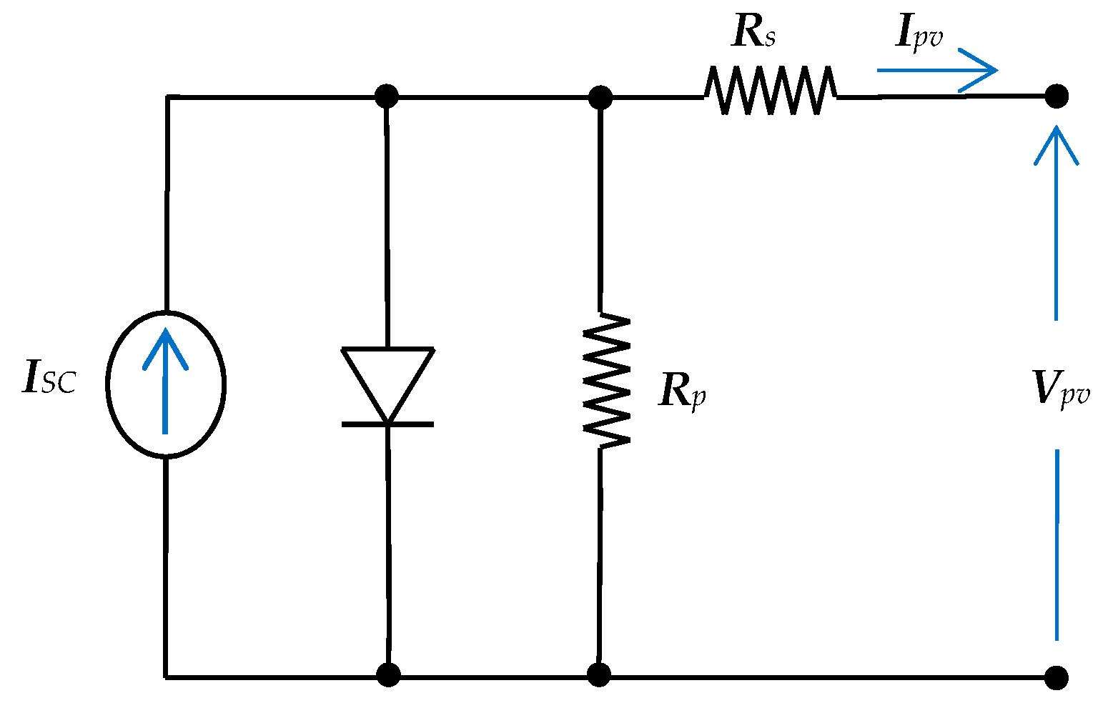
Figure 2 presents the PV panel model, which consisted of a current source with a parallel diode and series and parallel resistances. If the parallel resistance was large enough, its current was able to be neglected in the cell model. The equations of the model are well known in the literature [32].

3.2. Boost Converter Dynamic Model

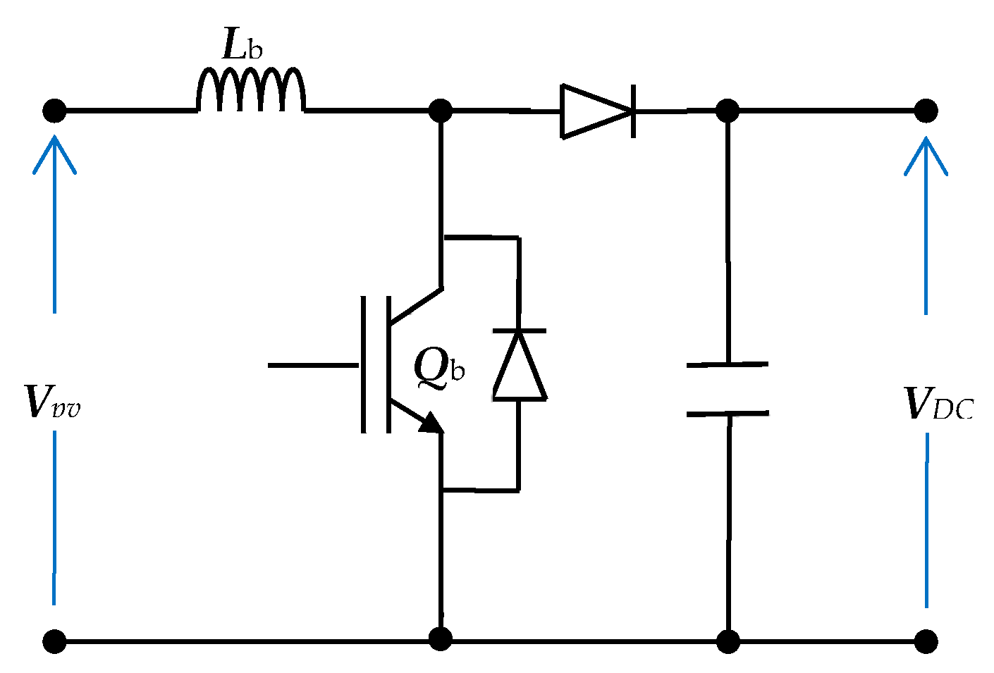
Figure 3 shows the power circuit of the boost converter. Its input is the PV panel output and the output feeds the DC link voltage of the 3-level transformerless inverter. Its function was to regulate the PV power to operate at MPPT conditions. Assuming that the DC link capacitor is large enough, the dynamic model of the converter is specified by the following equations [33]:
V p v = L b d I p v d t ,   Q b o n
V p v V D C = L b d I p v d t ,   Q b o f f
where Lb is the boost converter input inductance and (VDC) is the DC link voltage.

3.3. Three-Level Inverter and Filter Model

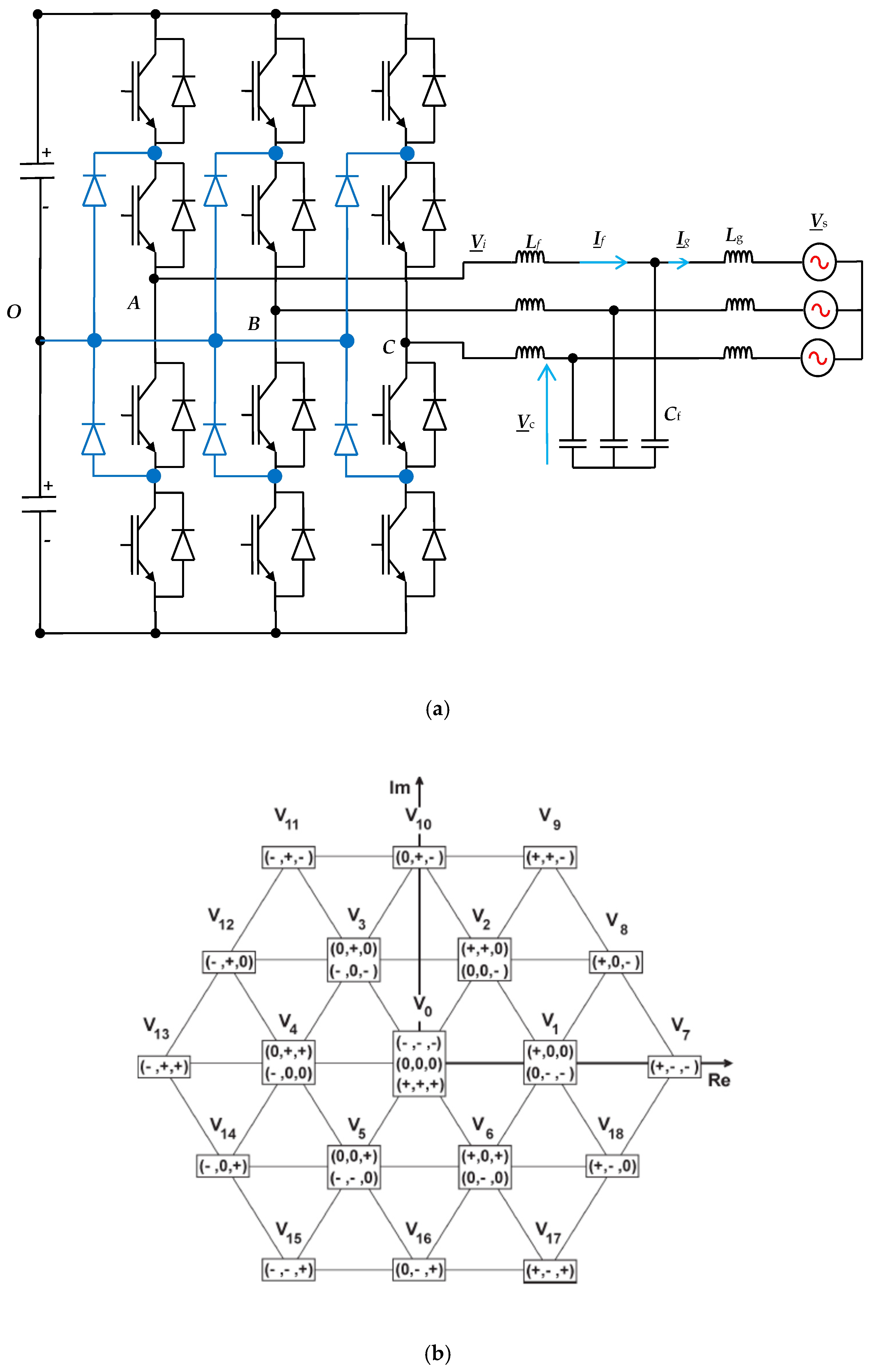
The power stage of the NPC 3-level inverter is shown in Figure 4a. It contains 12 Insolated Gate Bipolar Junction Transistor (IGBTs) and 6 clamp diodes. The DC bus voltage had to be split using two capacitors, as shown in the figure. It is well known that the NPC 3-level inverter has 27 states, as shown in Figure 4b. When these states are represented as space vectors, they produce 19 voltage vectors (V1,….V19). As stated in Reference [15], there are only seven states with zero common-mode voltage, named (V8, V10, V12, V14, V16, V18, V0). Hence, to limit the CMV of the NPC three-level inverter, the previous seven switching states were utilized. Consequently, the earth leakage current can be killed.
As shown in Figure 4a, the transformerless NPC inverter was connected to the grid through an LC filter. The source inductance (lg) was taken into consideration in the model. The grid was assumed to be an infinite 3-φ bus that had constant frequency and voltage amplitude. All 3-φ voltages and currents are expressed as space vectors using:
U _ = 2 / 3 ( u a + a u b + a 2 u c )
where (ua, ub, and uc) are the 3-φ quantities, u is the equivalent space vector, and a = ej(2π/3).
From the circuit’s basic laws, the system dynamic behavior can be expressed by:
L f d I _ f d t = V _ i V _ c
L g d I _ g d t = V _ c V _ s
C f d V _ c d t = I _ f I _ g
where (Lf, Cf) is the filter inductance and capacitance. The filter capacitor voltage vector is Vc, the inverter voltage vector is Vi, the grid current vector is Ig, and the filter current vector is If.

3.3.1. State Space Form of the 3-φ Transformerless Inverter Model

Equations (4)–(6) can be rewritten in the state space system matrix form:
X _ = [ I _ f I _ g V _ c ]
d X _ d t = A X _ + B V _ i + C V _ s
where
A = [ 0 0 1 L f 0 0 1 L g 1 C f 1 C f 0 ] ,   B = [ 1 L f 0 0 ] ,   C = [ 0 1 L g 0 ]

3.3.2. Discrete-Time Prediction of the 3-φ Transformerless Inverter Model

Implementation of the MPC algorithm requires prediction of the future values of the controlled quantities. The prediction process is accomplished using the system discrete model. Usually, this model is determined by the forward Euler approximation:
d X _ d t = X _ ( k + 1 ) X _ ( k ) T s
where Ts is the sampling time. With the help of Equation (10), the state space equation in (8) could be transformed into discrete as:
X _ ( k + 1 ) = A ˙ X _ ( k ) + B ˙ V _ i ( k ) + C ˙ V _ s ( k )
where
w ;   A ˙ = e A T s ,   B ˙ = 0 T s e A t B d t ,   C ˙ = 0 T s e A t C d t
From these equations, the system variables for the next sample can be predicted. An optimization process is then adapted to direct the system to the set point. This process will occur using the cost function.

4. System Controllers

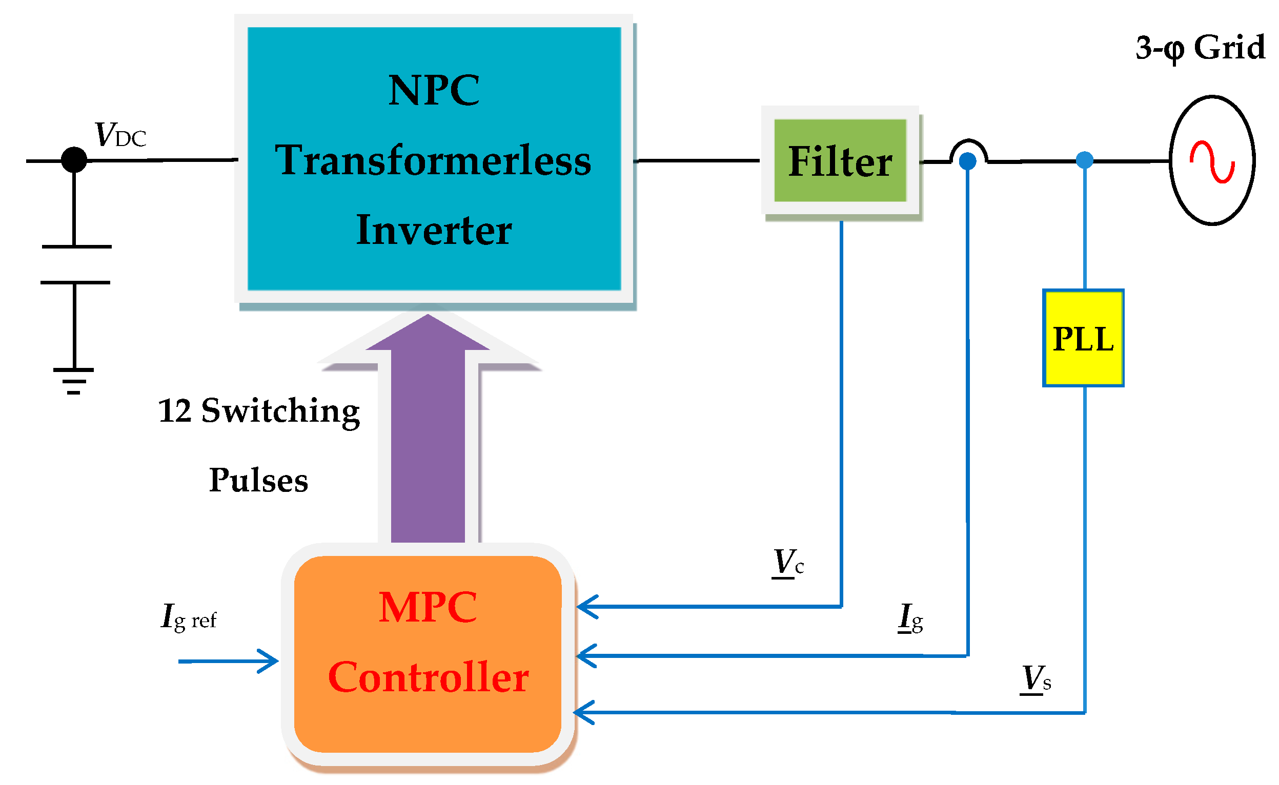
Here, three controllers are introduced to represent the control system for the suggested PV grid-tied system. The first controller is the MPPT controller that adjusts the PV operating point to be very close to the MPPT conditions. The MPPT algorithm generates the reference current to a current-regulated boost converter, which in turn maintains the MPPT conditions. The second controller is the DC link voltage controller that regulates VDC at a specified value. The third controller is used to regulate the grid current of the NPC transformerless inverter controller.

4.1. MPPT Controller

For better utilization of the PV systems, extracting maximum power is very important. Consequently, the operation at the MPPT condition is essential in these systems. Many techniques have been prepared for MPPT [34,35]. In this work, the incremental conductance MPPT approach was applied to utilize the maximum permissible PV power. The approach is based on tracking the slope of the PV power and voltage curve (dPpv/dVpv) until reaching zero, according to [30]:
Δ P Δ V   < 0             o n   t h e   r i g h t   o f   t h e   M P P T   c o n d i t i o n   a t   t h e   c u r v e Δ P Δ V = 0                                                                                                       a t   t h e   M P P T   c o n d i t i o n Δ P Δ V > 0                   o n   t h e   l i f t   o f   t h e   M P P T   c o n d i t i o n   a t   t h e   c u r v e
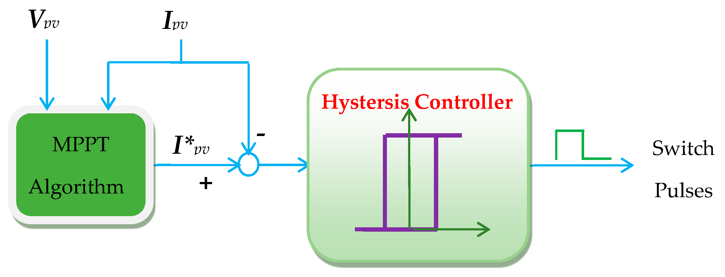
The incremental conductance approach produces the reference current to a current-regulated boost converter, as shown in Figure 5. The reference current is compared to the PV current generating an error signal that derives the hysteresis controller. In turn, the hysteresis controller produces the required duty cycle signals for the boost converter transistor.

4.2. DC Link Voltage Controller

This controller regulates the DC link voltage which has an important role in the power transfer and stability of the whole system. It generates the reference grid’s current value. For stability issues, the response of this controller must be slower than the inverter controller. Fortunately, the huge capacitor value at the DC link terminals decelerates the response of the system. As the set value is constant, the PI controller is adequate. The PI controller parameters are tuned by the Nichehols–Ziegler procedure.

4.3. NPC Inverter Controller Implemented Using the MPC Algorithm

The MPC scheme was based on predicting the future manipulated variables of the model to improve system performance. MPC schemes with power electronic systems are different since power electronic systems always use power converters. These converters usually have a limited number of feasible switching states. In those cases, the procedure depends on selecting the switching state which makes the system output as close as possible to its respective reference for each sampling period. For each sampling state, the behavior of the variables can be predicted by using the system model. Then, an optimization is adapted and applied to ensure selection of the appropriate and optimal switching state. This optimization is defined as a cost function that will be assessed for every promising switching state. Then, the optimal and suitable switching state is selected based on the minimization of the cost function obtained. The control structure of the proposed system is illustrated in Figure 6. The goals of this controller were to control the grid current vector (Ig) to track its sinusoidal reference and achieve unity power factor operation for the power supplied to the grid.
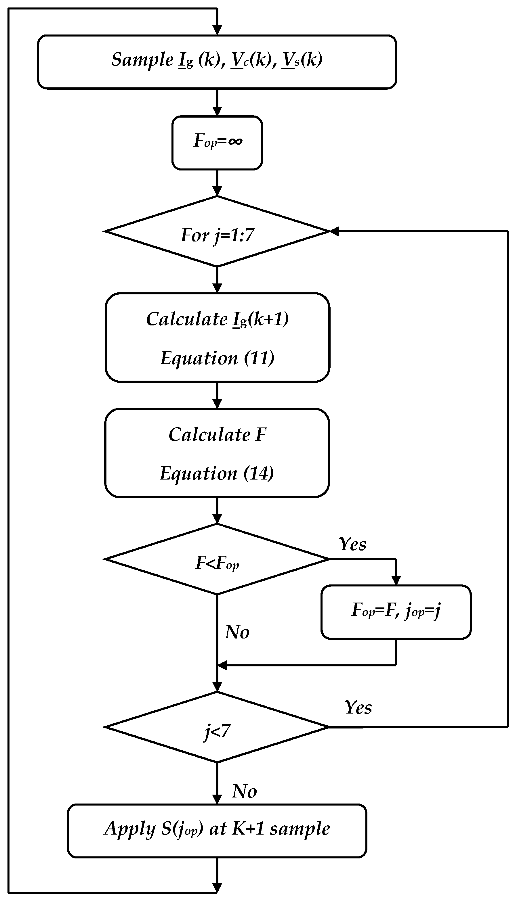
The prediction process relied on the measured variables, which were (Ig(k), Vs(k), Vc(k)). Next, the prediction of Ig(k + 1) for each effective switching state was obtained using the system model and measurements. In turn, the prediction assessed the cost function to obtain the control goals. Afterward, the valid switching state—which provides the minimum cost function—was designated for the next sampling period. Figure 7 shows a flow chart for the MPC controller of the NPC transformerless inverter.

Cost Function (F)

The cost function is the core of the MPC optimization process. To achieve the MPC goals, F is chosen to minimize the grid current error. F is defined as the square of grid current error, as given by:
F = ( i g α i g α * ) 2 + ( i g β i g β * ) 2
where (igα, i) are the real and imaginary components of Ig and (i*gα, i*) are the real and imaginary components of the grid current reference.

5. Simulation Results

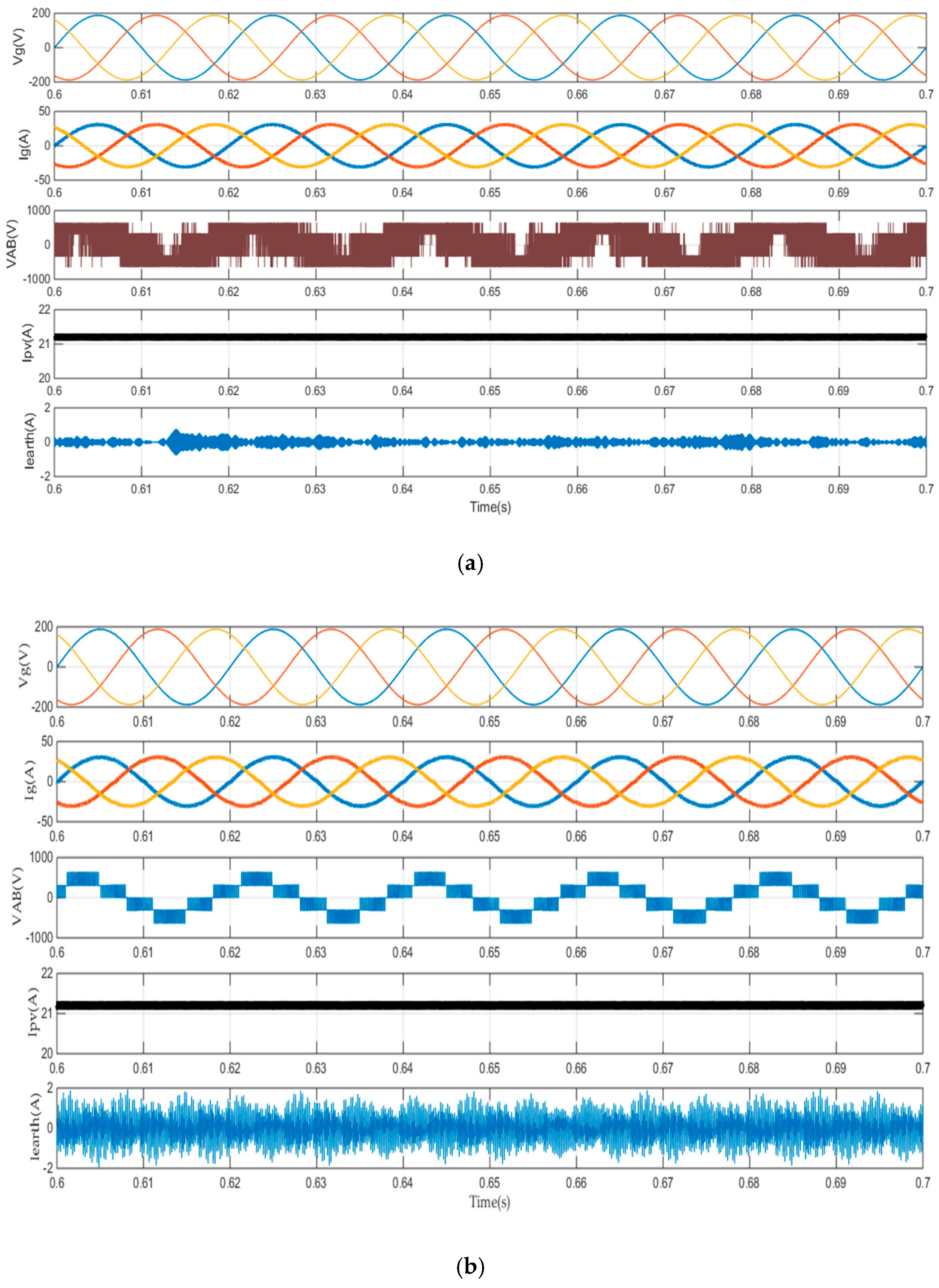
The proposed system shown in Figure 1 is simulated using the Matlab/Simulink platform. The system parameters are listed in Table 1. Typically, the power ratings of three-phase systems are 10–15 kW in the case of rooftop applications. This research used a 10 Kw power rating. Assuming that the 3-φ grid was (230 V, 50 Hz), the typical DC bus voltage VDC for the transformerless inverter was 650 V [1]. To achieve that value of VDC and output power of 10 Kw, the PV panel structure was 960 series cells × 6 parallel strings. The leakage capacitance (Cearth) between the cells and the grounded frame was modeled with a simple capacitance. It can have values up to 50–150 nF [36], depending on the atmospheric conditions and the structure of the panels. However, the value of (Cearth) in simulation was selected to be 100 nF. The sampling time (Ts) was selected based on the actual time for completing one control algorithm process. The remaining parameters were selected based on the fact they are commonly used, in practice, for 3-φ inverters. Figure 8 is a comparison of the results of the proposed NPC transformerless inverter controlled by the MPC controller (Figure 8a) and the PI current controller with SPW modulation. The 3-φ grid currents, with the two controllers, are sinusoidal and in phase with the grid voltage (unity power factor). The grid current THD with the MPC controller is 1.22% and with the PI controller is 2.23%. The inverter output line voltages have different waveforms as the controller action in each case is different. The PV currents for the two controllers are the same, as the same MPPT controller is used for each case. For earth leakage current, it is very clear that the MPC controller case is much smaller than the PI controller.
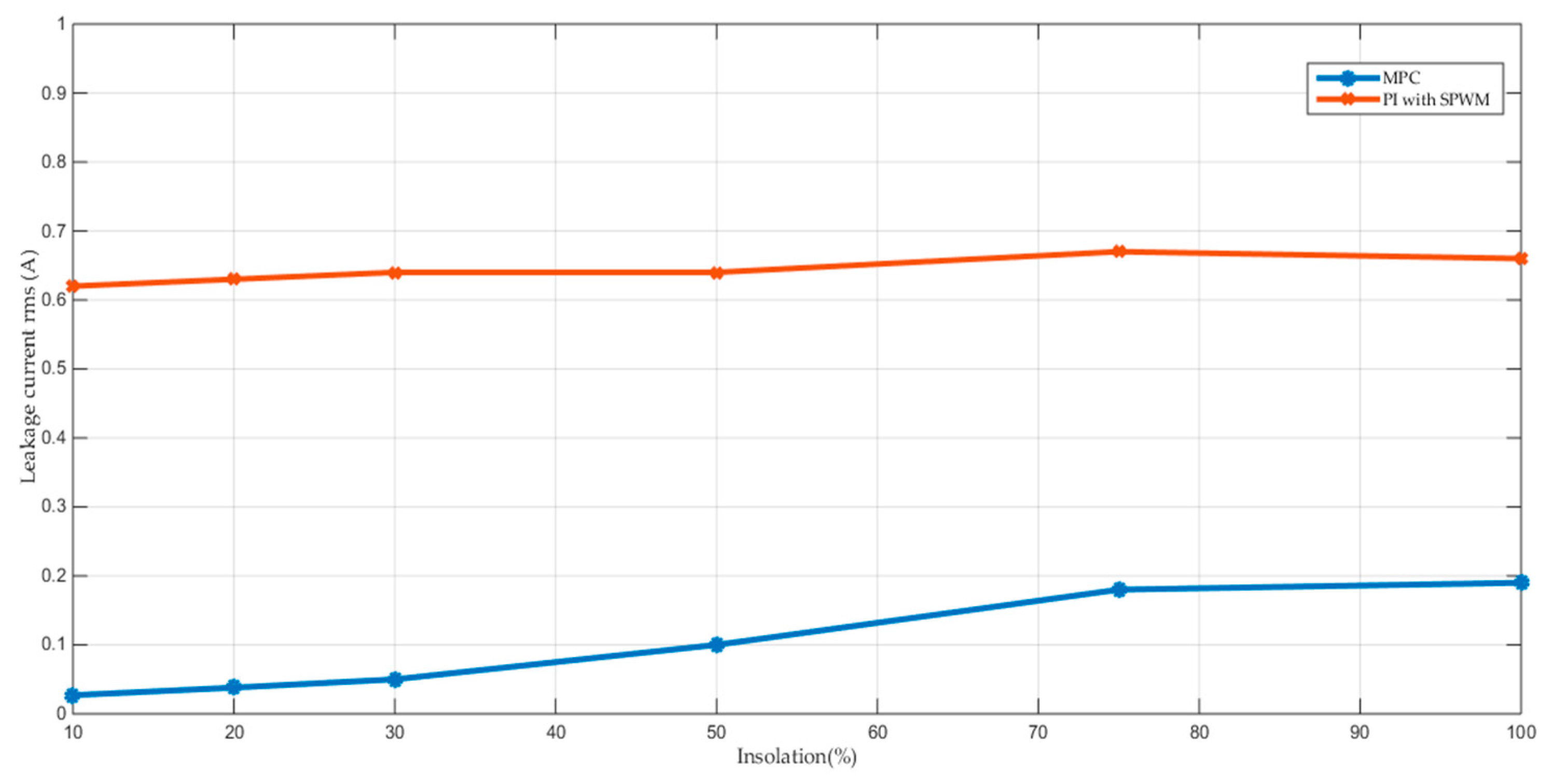
Figure 9 shows the variation of the Root Mean Square (RMS) value of the leakage current with the insolation level. The leakage current with the MPC case is less than one-third the value of the PI controller case. In MPC, not all the voltage vectors are used, only those that minimize leakage currents. The PI controller with SPW modulation utilizes all the voltage vectors. Hence, the leakage current is smaller in the MPC case. Furthermore, the leakage current drops for the MPC controller, while remaining nearly constant with the PI controller. This phenomenon is explained in the following paragraphs.
It is well known in the literature that CMV fluctuations are the main cause of leakage current. By checking the CMV of the two controllers, it was observed that with PI there were small CMV variations with the insolation variation. The MPC case had moderate CMV variations.
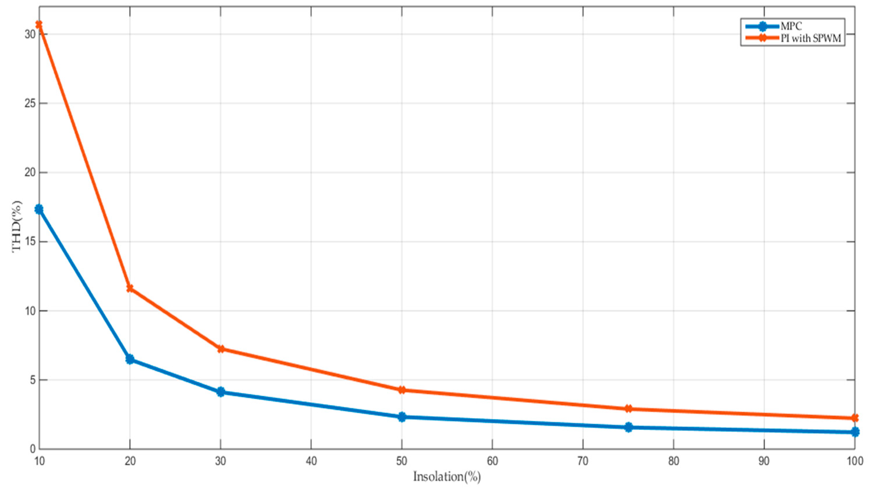
Figure 10 shows the variation of the grid current THD with the insolation level. Comparing the THD for the two cases shows that THD with MPC produces less than 50% of the value than THD with the PI controller. This result can be explained by the current-error-minimization process that occurs when the MPC controller is used.
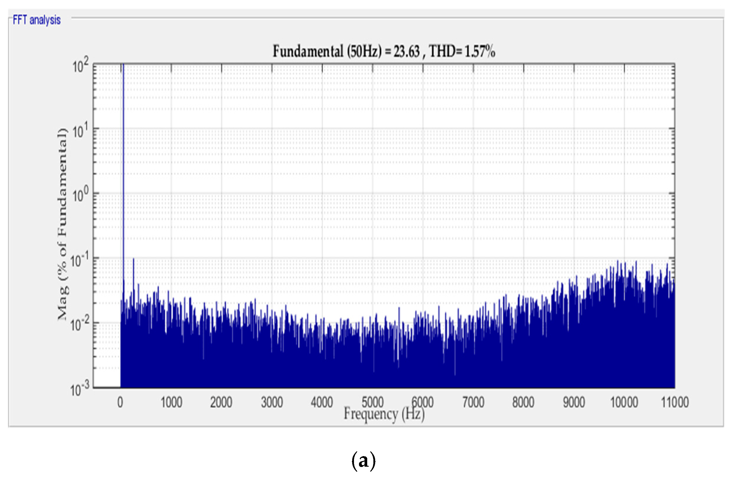
Figure 11 shows the variation of the frequency spectrum of the grid current with the insolation level. The figure shows that lower order harmonics in the MPC case are less than the lower order harmonics in the PI controller case. Generally, the value of the harmonics is lowest for MPC cases. The optimization mechanism in the MPC minimizes THD in the grid current since the cost function focuses on the error present in the grid current. The PI controller with the SPW modulation does not possess this optimization. For this reason, the THD is smaller in the MPC case than the other case.
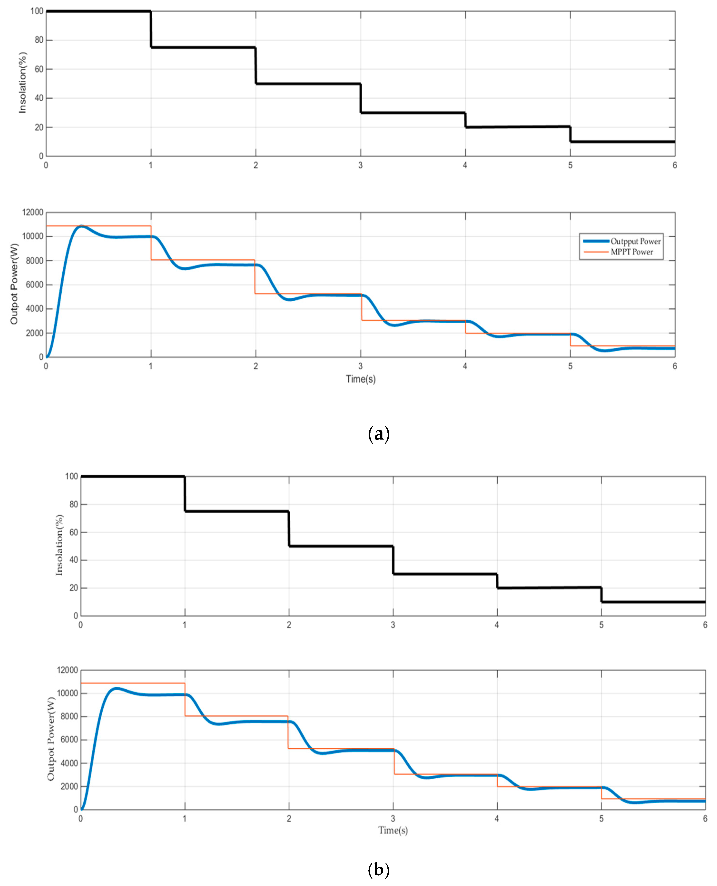
Figure 12 presents the response of the output power and maximum power point (MPP) power in the case of MPC controller (Figure 12a) and the PI current controller with SPW modulation (Figure 12b). The output power of the two cases tracks the MPP power with a forced steady-state error representing system losses. The losses in the MPC controller cases are smaller than in the PI controller cases. The reason for this difference is because a small THD produces harmonic losses. Losses increase with increasing power levels, which is considered a normal issue since current values increase as power levels increase.
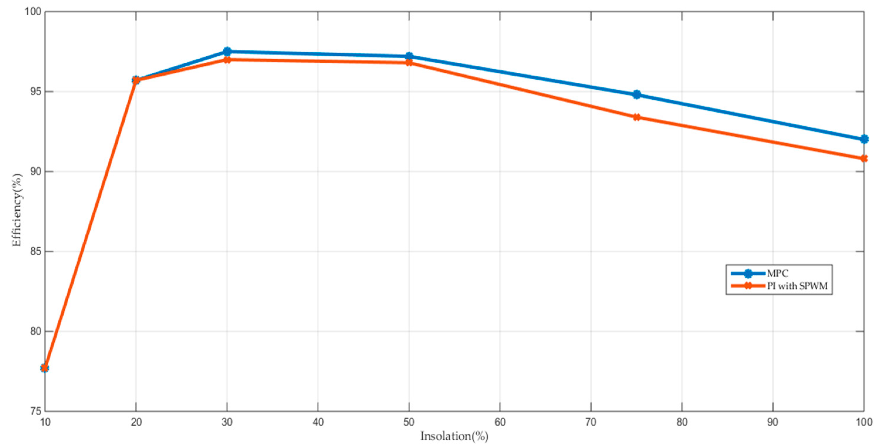
Figure 13 shows the variation of system efficiency with insolation level for the MPC controller and PI current controller with SPW modulation. Under all insolation levels, the efficiency of the MPC controller is higher than that for the PI controller. The proposed system Californian efficiency (η ηc) has been determined for the two controllers using the following equation [37]:
η C = 0.05 η 100 % + 0.21 η 75 % + 0.53 η 50 % + 0.12 η 30 % + 0.05 η 20 % + 0.04 η 10 %
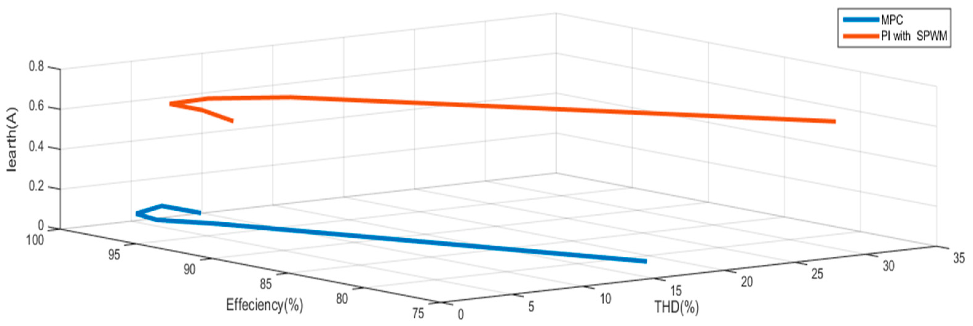
The efficiency is 95.62% for the MPC controller case and 94.99% for the PI current controller case. As the two compared cases use the same hardware, but have a different controller, the inverter switching pattern and harmonics are different. These differences are because the MPC controller provides better switching patterns and lower harmonics than other controllers. The higher efficiency is thought to come from the small switching losses and low harmonic losses from the MPC controller. Figure 14 provides a line diagram of the major performance factors, including THD, efficiency, and leakage current. The figure shows great improvement in leakage current reduction.

6. Conclusions

This article proposed application of an MPC controller with a PV-powered grid-tied NPC transformerless inverter. The transformerless inverter was linked with the grid through an LC filter. The filter elements, as well as the internal impedance of the grid, were taken into consideration in the system model. The discrete model of the proposed system was determined and the algorithm of the MPC controller was established. Matlab simulations of the proposed system (controlled by MPC) and a system that used an ordinary PI current controller with SPW modulation were carried out. The simulation results showed the following:
(1)
The MPC controller had the best performance for all factors of comparison.
(2)
The 3-φ grid currents, with the two controllers, were sinusoidal and in phase with the grid voltage (i.e., unity power factor).
(3)
The grid current THD with the MPC controller was 1.22% and 2.23% for the PI controller.
(4)
The leakage current in the MPC case was less than one-third of the value of the PI controller case.
(5)
The efficiency of the system that used the MPC was improved compared to the system that used the PI current controller with SPW modulation.

Author Contributions

S.A.Z. conceived and designed the system model. S.A.Z. and H.A. discussed the results. H.A. reviewed the paper.

Funding

This research was funded by University of Tabuk, grant number S-1440-0067 at https://www.ut.edu.sa/web/deanship-of-scientific-research/home.

Conflicts of Interest

The authors declare no conflict of interest.

Nomenclatures

CMVCommon-mode voltage
CMCCommon-mode current
CearthThe leakage capacitance
DPWMDiscontinuous PWM
DSPDigital signal processor
FThe cost function
IgThe grid current vector
IfThe filter current vector
IearthThe earth leakage current
ISCThe panel short circuit current
(i, i)The real and imaginary components of Ig
(i*, i*)The real and imaginary components of the grid current reference
lgThe source inductance
LbThe boost converter input inductance
(Lf, Cf)The filter inductance and capacitance.
MPPThe maximum power point
MPCModel predictive control.
MPPTMaximum power point tracking
NPCNeutral-point-clamped.
RSPWMRemote-state PWM
(Rp, Rs)The model parallel and series resistances
SPWMSinusoidal pulse width modulation
SVPWMSpace vector pulse width modulation
THDTotal harmonic distortion
TsThe sampling time
(ua, ub, and uc )The 3-φ quantities
uThe equivalent space vector
(Vpv, Ipv)The PV terminal voltage and current
VDCThe DC link voltage
VcThe filter capacitor voltage vector
ViThe inverter voltage vector
ZSIZ-Source Inverter
ZVRZero-voltage state rectifier
ηχCalifornian efficiency

References

  1. Kerekes, T.; Teodorescu, R.; Liserre, M.; Klumpner, C.; Sumner, M. Evaluation of three-phase transformerless photovoltaic inverter topologies. IEEE Trans. Power Electron. 2009, 24, 2202–2211. [Google Scholar] [CrossRef]
  2. Cavalcanti, M.C.; De Oliveira, K.C.; De Farias, A.M.; Neves, F.A.; Azevedo, G.M.; Camboim, F.C. Modulation techniques to eliminate leakage currents in transformerless three-phase photovoltaic systems. IEEE Trans. Ind. Electron. 2009, 57, 1360–1368. [Google Scholar] [CrossRef]
  3. Gupta, A.K.; Agrawal, H.; Agarwal, V. A Novel Three-Phase Transformerless H-8 Topology With Reduced Leakage Current for Grid-Tied Solar PV Applications. IEEE Trans. Ind. Appl. 2018, 55, 1765–1774. [Google Scholar] [CrossRef]
  4. Cavalcanti, M.C.; Farias, A.M.; Oliveira, K.C.; Neves, F.A.; Afonso, J.L. Eliminating leakage currents in neutral point clamped inverters for photovoltaic systems. IEEE Trans. Ind. Electron. 2011, 59, 435–443. [Google Scholar] [CrossRef]
  5. González, R.; Lopez, J.; Sanchis, P.; Marroyo, L. Transformerless inverter for single-phase photovoltaic systems. IEEE Trans. Power Electron. 2007, 22, 693–697. [Google Scholar] [CrossRef]
  6. Xiao, H.; Xie, S.; Chen, Y.; Huang, R. An optimized transformerless photovoltaic grid-connected inverter. IEEE Trans. Ind. Electron. 2010, 58, 1887–1895. [Google Scholar] [CrossRef]
  7. Kerekes, T.; Teodorescu, R.; Rodríguez, P.; Vázquez, G.; Aldabas, E. A new high-efficiency single-phase transformerless PV inverter topology. IEEE Trans. Ind. Electron. 2009, 58, 184–191. [Google Scholar] [CrossRef]
  8. Freddy, T.K.S.; Rahim, N.A.; Hew, W.P.; Che, H.S. Comparison and analysis of single-phase transformerless grid-connected PV inverters. IEEE Trans. Power Electron. 2013, 29, 5358–5369. [Google Scholar] [CrossRef]
  9. Bradaschia, F.; Cavalcanti, M.C.; Ferraz, P.E.; Neves, F.A.; dos Santos, E.C.; da Silva, J.H. Modulation for three-phase transformerless Z-source inverter to reduce leakage currents in photovoltaic systems. IEEE Trans. Ind. Electron. 2011, 58, 5385–5395. [Google Scholar] [CrossRef]
  10. Guo, X. Three-phase CH7 inverter with a new space vector modulation to reduce leakage current for transformerless photovoltaic systems. IEEE J. Emerg. Sel. Top. Power Electron. 2017, 5, 708–712. [Google Scholar] [CrossRef]
  11. Freddy, T.K.S.; Rahim, N.A.; Hew, W.P.; Che, H.S. Modulation techniques to reduce leakage current in three-phase transformerless H7 photovoltaic inverter. IEEE Trans. Ind. Electron. 2014, 62, 322–331. [Google Scholar] [CrossRef]
  12. Guo, X.; Zhang, X.; Guan, H.; Kerekes, T.; Blaabjerg, F. Three-phase ZVR topology and modulation strategy for transformerless PV system. IEEE Trans. Power Electron. 2018, 34, 1017–1021. [Google Scholar] [CrossRef]
  13. Krishna, R.A.; Suresh, L.P. A brief review on multilevel inverter topologies. In Proceedings of the International Conference on Circuit, Power and Computing Technologies (ICCPCT), Nagercoil, India, 18–19 March 2016; pp. 1–6. [Google Scholar] [CrossRef]
  14. Akbari, A.; Poloei, F.; Bakhshai, A. A Brief Review on State-of-the-art Grid-connected Inverters for Photovoltaic Applications. In Proceedings of the IEEE 28th International Symposium on Industrial Electronics (ISIE), Vancouver, BC, Canada, 12–14 June 2019; pp. 1023–1028. [Google Scholar] [CrossRef]
  15. Zhang, H.; Jouanne, A.V.; Dai, S.; Wallace, A.K.; Wang, F. Multilevel inverter modulation schemes to eliminate common-mode voltages. IEEE Trans. Ind. Appl. 2000, 36, 1645–1653. [Google Scholar] [CrossRef]
  16. Alepuz, S.; Busquets-Monge, S.; Bordonau, J.; Gago, J.; Gonzalez, D.; Balcells, J. Interfacing Renewable Energy Sources to the Utility Grid Using a Three-Level Inverter. IEEE Trans. Ind. Electron. 2006, 53, 1504–1511. [Google Scholar] [CrossRef]
  17. Correa, P.; Rodriguez, J.; Rivera, M.; Espinoza, J.R.; Kolar, J.W. Predictive Control of an Indirect Matrix Converter. IEEE Trans. Ind. Electron. 2009, 56, 1847–1853. [Google Scholar] [CrossRef]
  18. Mohamed, I.S.; Zaid, S.A.; Elsayed, H.M.; Abu-Elyazeed, M.F. Implementation of model predictive control for three-phase inverter with output LC filter on eZdsp F28335 Kit using HIL simulation. Int. J. Model. Identif. Control 2016, 25, 301–312. [Google Scholar] [CrossRef]
  19. Gulbudak, O.; Santi, E. A predictive control scheme for a dual output indirect matrix converter. In Proceedings of the IEEE Applied Power Electronics Conference and Exposition (APEC), Charlotte, NC, USA, 15–19 March 2015; pp. 2828–2834. [Google Scholar] [CrossRef]
  20. Vazquez, S.; Leon, J.; Franquelo, L.; Rodriguez, J.; Young, H.A.; Marquez, A.; Zanchetta, P. Model Predictive Control: A Review of Its Applications in Power Electronics. IEEE Ind. Electron. Mag. 2014, 8, 16–31. [Google Scholar] [CrossRef]
  21. Corts, P.; Kazmierkowski, M.P.; Kennel, R.M.; Quevedo, D.E.; Rodrguez, J. Predictive control in power electronics and drives. IEEE Trans. Ind. Electron. 2008, 55, 4312–4324. [Google Scholar] [CrossRef]
  22. Corts, P.; Ortiz, G.; Yuz, J.I.; Rodrguez, J.; Vazquez, S.; Franquelo, L.G. Model predictive control of an inverter with output LC filter for UPS applications. IEEE Trans. Ind. Electron. 2009, 56, 1875–1883. [Google Scholar] [CrossRef]
  23. Mohamed, I.S.; Zaid, S.A.; Elsayed, H.M.; Abu-Elyazeed, M.F. Improved model predictive control for three-phase inverter with output LC filter. Int. J. Model. Identif. Control 2015, 23, 371–379. [Google Scholar] [CrossRef]
  24. Wang, J. Model Predictive of Power Electronic Converter. Master’s Thesis, Norwegian University of Science and Technology, Norway, Trondheim, 2012. [Google Scholar]
  25. Vaccari, M.; Pannocchia, G. A Modifier-Adaptation Strategy towards Offset-Free Economic MPC. Processes 2017, 5, 2. [Google Scholar] [CrossRef]
  26. Li, W.; Kong, D.; Xu, Q.; Wang, X.; Zhao, X.; Li, Y.; Han, H.; Wang, W.; Chen, Z. A Wind Farm Active Power Dispatch Strategy Considering the Wind Turbine Power-Tracking Characteristic via Model Predictive Control. Processes 2019, 7, 530. [Google Scholar] [CrossRef]
  27. Xiaodong, W.; Zou, J.; Ma, L.; Zhao, J.; Xie, C.; Li, K.; Meng, L.; Guerrero, J.M. Model predictive control methods of leakage current elimination for a three-level T-type transformerless PV inverter. IET Power Electron. 2018, 11, 1492–1498. [Google Scholar] [CrossRef]
  28. Vargas, R.; Cortes, P.; Ammann, U.; Rodriguez, J.; Pontt, J. Predictive Control of a Three-Phase Neutral-Point-Clamped Inverter. IEEE Trans. Ind. Electron. 2007, 54, 2697–2705. [Google Scholar] [CrossRef]
  29. Rockhill, A.A.; Liserre, M.; Teodorescu, R.; Rodriguez, P. Grid-Filter Design for a Multimegawatt Medium-Voltage Voltage-Source Inverter. IEEE Trans. Ind. Electron. 2011, 58, 1205–1217. [Google Scholar] [CrossRef]
  30. Zaid, S.A.; Kassem, A.M. Review, analysis and improving the utilization factor of a PV-grid connected system via HERIC transformerless approach. Renew. Sustain. Energy Rev. 2017, 73, 1061–1069. [Google Scholar] [CrossRef]
  31. Liserre, M.; Teodorescu, R.; Blaabjerg, F. Stability of photovoltaic and wind turbine grid-connected inverters for a large set of grid impedance values. IEEE Trans. Power Electron. 2006, 21, 263–272. [Google Scholar] [CrossRef]
  32. Atia, Y. Photovoltaic Maximum Power Point Tracking Using SEPIC Converter. Eng. Res. J. 2009, 36, 33–40. [Google Scholar]
  33. Rashid, M. Power Electronics Handbook, 2nd ed.; Elsevier Academic Press: Amsterdam, The Netherlands, 2011. [Google Scholar]
  34. Husain, M.A.; Tariq, A.; Hameed, S.; Arif, M.S.B.; Jain, A. Comparative assessment of maximum power point tracking procedures for photovoltaic systems. Green Energy Environ. 2017, 2, 5–17. [Google Scholar] [CrossRef]
  35. Das, P. Maximum power tracking based open-circuit voltage method for PV system. Energy Procedia 2016, 90, 2–13. [Google Scholar] [CrossRef]
  36. Elbalawi, H.; Zaid, S.A. H5 Transformerless Inverter for Grid Connected PV System with Improved Utilization Factor and Simple Maximum Power Point Algorithm. Energies 2018, 11, 2912. [Google Scholar] [CrossRef] [Green Version]
  37. Schmidt, H.; Burger, B.; Siedle, C. Gefährdungspotenzial transformatorloser Wechselrichter—Fakten und Gerüchte. In Proceedings of the 18th Symposium Photovoltaische Sonnenenergie, Staffelstein, Germany, 12–14 March 2003; pp. 89–98. [Google Scholar]
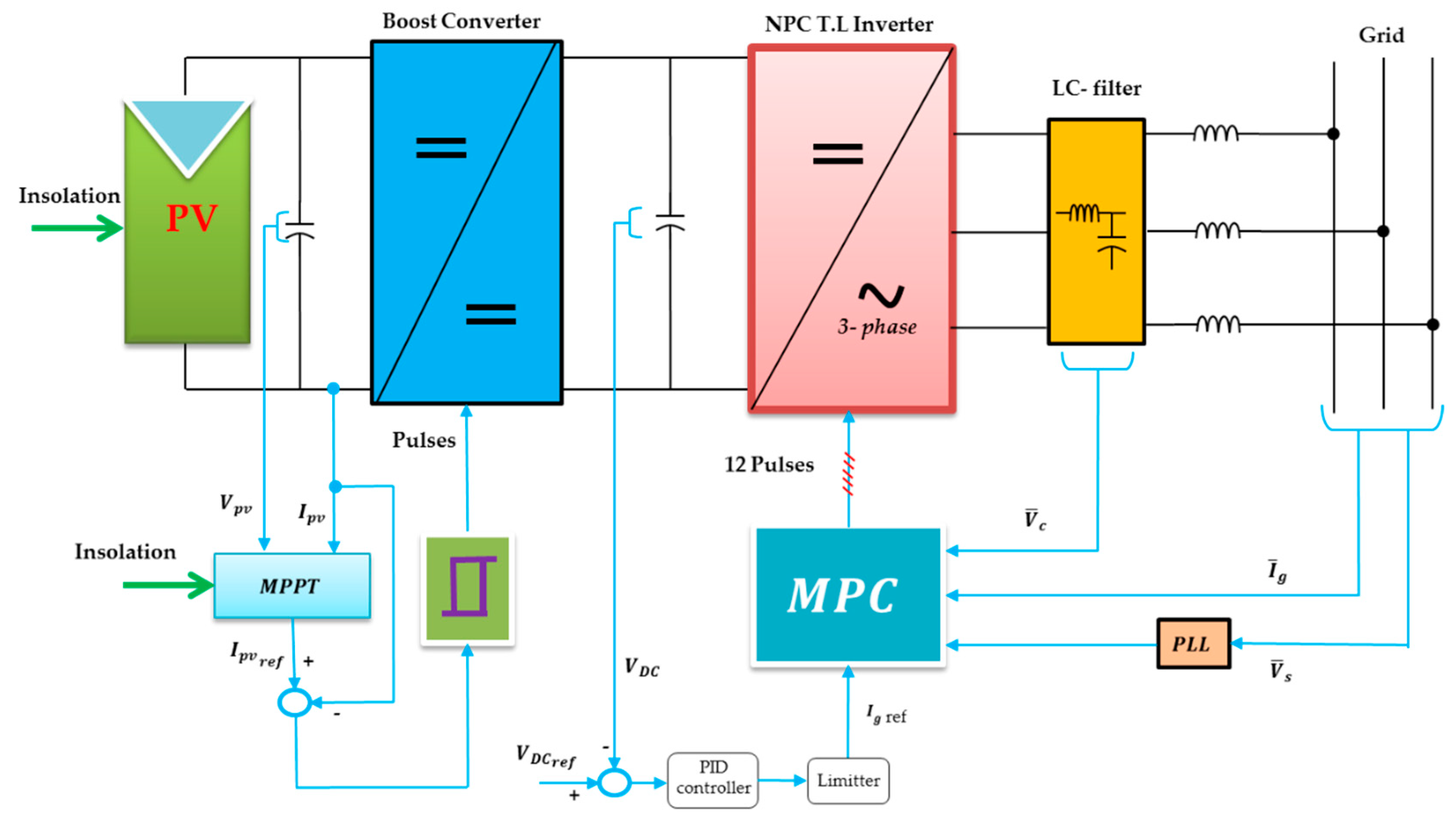
Figure 1. The proposed photovoltaic (PV)-powered 3-level transformerless inverter connected to the grid and its controllers.
Processes 07 00856 g001
Figure 2. Model of the PV panel, where ISC is the panel short circuit current and (Rp, Rs) is the model parallel and series resistances.
Processes 07 00856 g002
Figure 3. The power circuit of the boost converter.
Processes 07 00856 g003
Figure 4. (a) The power circuit diagram of an NPC 3-φ inverter and (b) the inverter space vectors.
Processes 07 00856 g004
Figure 5. Maximum power point tracking (MPPT) controller block diagram.
Processes 07 00856 g005
Figure 6. Model predictive control (MPC) block diagram.
Processes 07 00856 g006
Figure 7. MPC algorithm flowchart.
Processes 07 00856 g007
Figure 8. Simulation results of the proposed neutral-point-clamped (NPC) transformerless inverter in terms of grid voltage, grid current, PV current, and earth leakage current with (a) the MPC controller and (b) the proportional–integral (PI) current controller with sinusoidal pulse width modulation (SPWM).
Processes 07 00856 g008
Figure 9. Variation of the leakage current with the insolation level for the MPC controller and PI current controller with SPW modulation.
Processes 07 00856 g009
Figure 10. Variation of the grid current total harmonic distortion (THD) with the insolation level for the MPC controller and PI current controller with SPW modulation.
Processes 07 00856 g010
Figure 11. The spectrum of the grid current for the (a) MPC controller and (b) PI current controller with SPW modulation (@75%insolation).
Processes 07 00856 g011aProcesses 07 00856 g011b
Figure 12. The maximum power point (MPP) power and output power at step insolation variations for the (a) MPC controller and (b) PI current controller with SPWM.
Processes 07 00856 g012
Figure 13. Variation of the system efficiency with the insolation level for the MPC controller and PI current controller with SPW modulation.
Processes 07 00856 g013
Figure 14. Line diagram of the THD, efficiency, and leakage current for the MPC controller and PI current controller with SPW modulation.
Processes 07 00856 g014
Table 1. System parameters.
ParameterValue
PV SC current24.53 A
PV OC voltage 633 V
Cearth 100 nF
VDC 650 V
Cf2 µF
Lf3 mH
Utility voltage 230 V
Utility frequency50 Hz
PWM carrier frequency10 KHz
DC link capacitor1000 µF
Ts35 µs