Article

Natural Frequency Sensitivity Analysis of Fire-Fighting Jet System with Adaptive Gun Head

1
Hebei Key Laboratory of Heavy Machinery Fluid Power Transmission and Control, Yanshan University, Hebei, Qinhuangdao 066004, China
2
State Key Laboratory of Fluid Power & Mechatronic Systems, Zhejiang University, Zhejiang, Hangzhou 310027, China
3
National Research Center of Pumps, Jiangsu University, Zhenjiang 212013, China
*
Authors to whom correspondence should be addressed.
Processes 2019, 7(11), 808; https://doi.org/10.3390/pr7110808
Submission received: 14 October 2019 / Revised: 25 October 2019 / Accepted: 28 October 2019 / Published: 4 November 2019
(This article belongs to the Special Issue Smart Flow Control Processes in Micro Scale)

Abstract

:
The gun head is the end effector of the fire-fighting jet system. Compared with a traditional fixed gun head, an adaptive gun head has the advantages of having an adjustable nozzle opening, a wide applicable flow range, and a high fire-extinguishing efficiency. Thus, the adaptive gun head can extinguish large fires quickly and efficiently. The fire-fighting jet system with an adaptive gun head has fluid-structure interaction and discrete-continuous coupling characteristics, and the influence of key design parameters on its natural frequencies needs to be determined by a sensitivity analysis. In this paper, the dynamic model and equations of the jet system were established based on the lumped parameter method, and the sensitivity calculation formulas of the natural frequency of the jet system to typical design parameters were derived. Natural frequencies and mode shapes of the jet system were determined based on a mode analysis. The variation law of the sensitivity of the natural frequency of the jet system to typical design parameters was revealed by the sensitivity analysis. The results show that the fluid mass inside the spray core within a certain initial gas content is the most important factor affecting the natural frequency of the jet system. There was only a 0.51% error between the value of the first-order natural frequency of the jet system determined by the modal experiment and the theoretical one, showing that good agreement with the first-order natural frequency of the jet system was found. This paper provides a theoretical basis for the dynamic optimization design of the adaptive gun head of the fire water monitor.

1. Introduction

The fire-fighting monitor is an important fire-fighting equipment for long-range fire extinguishing and has become an important part of fire-extinguishing systems in large-scale places [1,2,3]. According to different spray media, the fire-fighting monitor can be divided into two series: a fire water monitor and a fire foam monitor. Structurally, the fire-fighting monitor is mainly composed of a barrel and a gun head. The barrel mainly includes components such as a motor, a reducer, and an elbow, which can realize horizontal and pitching rotation of the jet direction of the fire-fighting monitor. The gun head is the key component that converts the pressure energy of the fluid into kinetic energy and its working principle is similar to that of a valve component in a hydraulic transmission system [4,5,6]. Compared with a traditional fixed gun head, the adaptive gun head can automatically adjust the nozzle opening through an adaptive mechanism when the flow and pressure of the fluid change at the entrance of the gun head, so that the performance of the jet system can be better in a wider flow range and fire extinguishing efficiency can be higher.
A sensitivity analysis is a method to study the sensitivity of the system in response to changes in its design parameters, through which the influence degree of design variables on output variables can be sorted. In the process of structural optimization design and parameter identification, the sensitivity analysis can be used to identify important parameters while ignoring unimportant variables, thereby significantly reducing the dimensionality of the design space, providing a basis for identifying weak points in the system [7,8]. When the functional relationship between inputs and outputs is known, the sensitivity of the system can be calculated by the partial derivative of the response function to the design variable. This direct calculation method is generally applicable when the design factor is few, the structure is not complicated, and the sensitivity differential equation is easy to derive. In this case, the method has the characteristics of simplified calculating and can resolve the essential relationship between inputs and outputs. When it is difficult or impossible to determine the analytical relationship between inputs and outputs, the Monte Carlo method, orthogonal test, Kriging, and other modern approximation design methods are generally used to determine the implicit functional relationship between design variables and responses; then the gradient method and the genetic algorithm can be used to calculate the sensitivity of the system. This method of indirect calculation is generally applicable to the case of many design factors, complicated structures, and complex nonlinear relationship between input and output parameters. The method is characterized by a large computational workload, and the error of the determined sensitivity is positively correlated with sample capacity [9,10,11]. The sensitivity analysis is widely used in various fields such as chemistry [12,13], construction [14,15], environmental protection [16], transportation [17], and machinery [18,19,20,21].
The fire-fighting jet system with the adaptive gun head consists of an adaptive gun head, a barrel, a connecting pipe, and its internal fluid. The analysis process of the fluid-structure interaction and discrete-continuous coupling problems in the jet system should be analogized to that of the influencing factors of the dynamic characteristics of valve components [22,23]. Through the sensitivity analysis, the key design parameters affecting the dynamic characteristics of the fire-fighting jet system are discussed. The fire-fighting jet system is subjected to the pressure pulsation of the power element pump in operation, so that the jet system inevitably generates vibration and noise [24,25,26]. When an adaptive fire-fighting monitor is used instead of a conventional fire-fighting monitor, the stiffness of the end of the jet system is reduced, increasing the tendency of the jet system to resonate. Therefore, the sensitivity analysis can be used to explore the parameters affecting the modal characteristics of the jet system, which can provide theoretical reference for the dynamic optimization design of the adaptive fire-fighting monitor.
In this paper, based on the fluid-structure interaction and discrete-continuous coupling characteristics of the jet system, the dynamic model and equations of the free vibration of the jet system will be established. The sensitivity calculation formulas of the modal characteristics of the jet system to typical design parameters will be derived. The influence law of the modal characteristics of the jet system for each parameter will be analyzed, and the first-order natural frequency of the jet system will be verified according to the modal experiment.

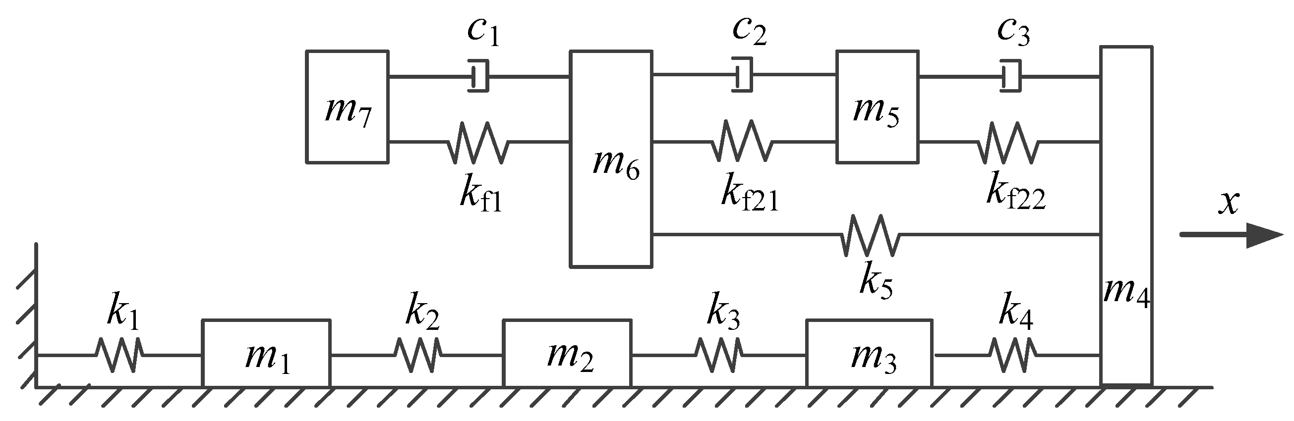
2. Establishment of the Dynamic Model and Equations of the Jet System

The structure of the gun head of the traditional diversion fire-fighting monitor is shown in Figure 1. The structure of the gun head of the new adaptive fire-fighting monitor is shown in Figure 2. The traditional diversion gun head can achieve both straight and spray jets by changing the relative positions of the inner and outer nozzles to meet the fire suppression requirements of different occasions. However, since the internal components are fixedly connected, the opening of the nozzles remains unchanged during the working process. Therefore, when the jet flow changes, the nozzle opening does not match the flow rate, and the fire extinguishing efficiency is low. In contrast, the new adaptive gun head adds an adaptive mechanism consisting of the spray core 9, the end cap 10, the core rod 11, and the spring 12 on the basis of the traditional diversion gun head. When the inlet flow of the gun head increases, the pressure on the left side of the spray core of the adaptive mechanism increases. When the force of the spray core received by the fluid is greater than that of the spring, the spray core moves to the right and the nozzle opening increases. Conversely, when the inlet flow rate is decreased, the spray core moves to the left and the nozzle opening decreases. The adaptive mechanism enables the gun head to automatically adjust the nozzle opening according to changes in inlet flow and pressure, thereby achieving good jet performance under various conditions and extinguishing large fires quickly and effectively.
The new adaptive gun head shown in Figure 2 is mounted on the horizontally-rotating and pitch-turning barrel, and combined with the pipes connected to the barrel. The structure above constitutes the fire-fighting jet system with the adaptive gun head studied in this paper, as shown in Figure 3.
The fire-fighting jet system with the adaptive gun head has typical fluid-structure interaction characteristics due to the interaction between the fluid, spray core, and spring in the working process. Moreover, the fluid-structure interaction between the fluid unit and the solid unit in the jet system only occurs at the interface between the two. The interaction between the units in the jet system is shown in Figure 4.
In Figure 4, fluid unit 2 is the entire fluid volume enclosed by the inside of the spray core and the core rod-end cap structure. Fluid unit 1 is all fluids in the gun head, the barrel, and the pipes connected to the barrel except fluid unit 2. The fluid units and solid units in the jet system are coupled to each other and interact to make the dynamic modeling and analysis more complicated. To facilitate theoretical analyses, the established overall dynamic model of the jet system follows the following assumptions:
(1)
The jet system is modeled based on the lumped parameter method. It is considered that the density, stiffness, pressure, and other attribute parameters of each fluid unit in the jet system are evenly distributed in the control volume and equal everywhere;
(2)
Except for the fluid units and the spring, it is considered that the parts such as the spray core, the gun head enclosure, the barrel, and the outer wall of the pipe are rigid bodies, regardless of their deformation;
(3)
The spray core, the core rod-end cap structure, and each fluid unit are only affected by the axial force, and the force of the fluid units on the solid units is equivalent to the axial linear spring force;
(4)
The damping between the fluid units and the solid units is equivalent to axial linear damping;
(5)
Ignore the processing and installation errors of each component.
In the fire-fighting jet system with the adaptive gun head, the inside spray core, fluid unit 1, and fluid unit 2 can be viewed as discrete bodies, and the core rod-end cap structure can be regarded as a continuum due to the particularity of its shape. Therefore, the jet system has not only fluid-structure interaction characteristics, but also discrete-continuous coupling characteristics. The discrete-continuous coupling characteristics in the jet system will increase the difficulty of dynamic modeling and analysis, so the core rod-end cap structure needs to be equally discrete, thus simplifying the problem.
Based on the above analysis and assumptions, the dynamic model of the fire-fighting jet system with adaptive gun head is shown in Figure 5. Among them, the structure consisting of m 1 , m 2 , m 3 , m 4 , k 1 , k 2 , k 3 , and k 4 is the equivalent discrete model of the core rod-end cap structure. m 1 , m 2 , and m 3 are 1/4 of the mass of the core rod, m 4 is the sum of the mass of the 1/4 core rod and the mass of the end cap, and k 1 , k 2 , k 3 , and k 4 are equal in size. m 5 , m 6 , and m 7 are the mass of fluid unit 2, the spray core, and fluid unit 1, respectively. k f 1 , k f 2 1 , and k f 22 are fluid stiffnesses. k f 1 is the stiffness of fluid unit 1. k f 2 1 and k f 22 are numerically equal, and the total stiffness after the parallel connection is the stiffness of fluid unit 2. k 5 is the stiffness of the spring in the adaptive mechanism of the gun head. c 1 is the damping of fluid unit 1. c 2 and c 3 are numerically equal, and the total damping after the parallel connection is the sum of the damping of fluid unit 2 and the damping of the spray core’s orifice structure.
Based on the dynamic model of the fire-fighting jet system with the adaptive gun head, the free vibration equation of the jet system is established as
m x ¨ + k x = 0 ,
where the mass matrix of the jet system is
m = diag ( m 1 , m 2 , m 3 , m 4 , m 5 , m 6 , m 7 ) ,
where the stiffness matrix of the jet system is
k = [ k 1 + k 2 k 2 0 0 0 0 0 k 2 k 2 + k 3 k 3 0 0 0 0 0 k 3 k 3 + k 4 k 4 0 0 0 0 0 k 4 k 4 + k f 22 + k 5 k f 22 k 5 0 0 0 0 k f 22 k f 21 + k f 22 k f 21 0 0 0 0 k 5 k f 21 k f 21 + k 5 + k f 1 k f 1 0 0 0 0 0 k f 1 k f 1 ] .
In the stiffness matrix of the jet system, the stiffness of each fluid unit is calculated equivalently. By the definition of stiffness, there is
k f = Δ F Δ L = S a Δ p Δ L ,
where Δ F is the amount of load fluctuation of the fluid unit, Δ L is the axial length change of the fluid unit, S a is the average area of the flow cross section of the fluid unit, Δ p is the change of fluid pressure, and L is the axial length of the fluid unit.
The volume of the fluid unit obtained from the average area of the flow cross section of the fluid unit and the axial length of the fluid unit is
V = S a L .
The bulk elastic modulus of the fluid in the fire-fighting jet system with the adaptive gun head is calculated according to the theory of bulk elastic modulus described in [27]. Let the bulk elastic modulus of the fluid be B f , which is defined as
B f = V Δ p Δ V ,
where V is the total volume of the fluid, and Δ V is the volume change of the fluid.
For Equations (4)–(6), the fluid equivalent stiffness can be expressed by the bulk elastic modulus of the fluid:
k f = B f S a L .
As can be seen from Figure 3, the shapes of fluid unit 1 and fluid unit 2 are relatively complicated. In order to improve the calculation accuracy of the fluid equivalent stiffness, fluid unit 1 is divided into six segments and fluid unit 2 is divided into three segments according to the shape of the structure. The first section of fluid unit 1 is a pipe connected to the fire-fighting monitor’s barrel and the inlet end of the barrel. Parameters of each section of the two fluid units are shown in Table 1. The equivalent stiffness of each fluid unit subsection can be calculated separately from Equation (7).
The equivalent stiffness of fluid unit 1 and fluid unit 2 can be obtained from the series relationship of the equivalent fluid springs of the fluid unit subsections, where the equivalent stiffness of fluid unit 1 is
1 k f 1 = 1 k f 1 1 + 1 k f 1 2 + 1 k f 13 + 1 k f 14 + 1 k f 15 + 1 k f 16 .
The equivalent stiffness of fluid unit 2 is
1 k f 2 = 1 k f 2 1 + 1 k f 2 2 + 1 k f 23 .
Since k f 2 1 and k f 22 are connected in parallel to be the equivalent stiffness of fluid unit 2 and they are equal in size, then:
k f 21 = k f 22 = k f 2 2 .

3. Derivation of the Sensitivity Formula of the Jet System

The free vibration differential equation of the fire-fighting jet system with the adaptive gun head is shown in Equation (1), and its corresponding characteristic equation is
( k ω n i 2 m ) ϕ i = 0 ,
where ω n i is natural angular frequency (rad/s), ϕ i is the principal mode.
Equation (11) left multiplies ϕ i T , then
ϕ i T ( k ω n i 2 m ) ϕ i = 0 .
Assuming that the design variable t , the natural frequency ω n i , the stiffness matrix k , and the mass matrix m are derivable and ω n i is a single eigenvalue, then ω n i is differentiable with respect to design variables. The first-order partial derivatives of both sides of Equation (12) with respect to the design variable t are
ϕ i T t ( k ω n i 2 m ) ϕ i + ϕ i T ( k t ( ω n i 2 m ) t ) ϕ i + ϕ i T ( k ω n i 2 m ) ϕ i t = 0
Since ( k ω n i 2 m ) is a real symmetric matrix, ϕ i T is also the eigenvalue of the characteristic Equation (11), so
ϕ i T ( k ω n i 2 m )   =   0 .
Substituting Equations (11) and (14) into Equation (13), then
ϕ i T ( k t 2 ω n i ω n i t m ω n i 2 m t ) ϕ i = 0 .
The formula for calculating the sensitivity of each order natural frequency ω n i to the design variable t from Equation (15) is
ω n i t = 1 2 m p i ( 1 ω n i ϕ i T k t ϕ i ω n i ϕ i T m t ϕ i ) ,
where m p i = ϕ i T m ϕ i and m t and k t are determined according to specific design parameters.
In the dynamic model of the fire-fighting jet system with the adaptive gun head, the mass and stiffness of the fluid unit are directly related to its density and bulk elastic modulus. Moreover, the density and bulk elastic modulus of the fluid unit are both functions of fluid pressure and initial gas content of the fluid. Therefore, analyzing the influence of fluid mass and stiffness on the natural frequency sensitivity of the jet system is essential to analyze the influence of fluid pressure and initial gas content on the natural frequency sensitivity of the jet system.

3.1. Sensitivity of the Natural Frequency of the Jet System to the Mass of Fluid Unit 1

The density of fluid unit 1 is equal to that of fluid unit 2, and the density of the fluid can be regarded as a function of fluid pressure and initial gas content in the jet system. Therefore, the change of m 7 indicates that the fluid pressure or initial gas content in the jet system has changed, which leads to the change of m 5 . Meanwhile, m 1 , m 2 , m 3 , and m 4 are sub-mass units of the core rod-end cap structure, and their values are independent of m 7 . Using the mass matrix of the jet system shown in Equation (2), the partial derivative of the mass matrix of the jet system with respect to the mass of fluid unit 1 m 7 is
m m 7 = diag ( 0 , 0 , 0 , 0 , m 5 m 7 , 0 , 1 ) ,
where
m 5 m 7 = ( V m 5 ρ water ) ( V m 7 ρ water ) = V m 5 V m 7 .
Using the stiffness matrix of the jet system shown in Equation (3), the partial derivative of the stiffness matrix of the jet system with respect to the mass of fluid unit 1 m 7 is
k m 7 = [ 0 0 0 0 0 0 0 0 0 0 0 0 0 0 0 0 0 0 0 0 0 0 0 0 k f 22 m 7 k f 22 m 7 0 0 0 0 0 k f 22 m 7 k f 22 m 7 + k f 21 m 7 k f 21 m 7 0 0 0 0 0 k f 21 m 7 k f 21 m 7 + k f 1 m 7 k f 1 m 7 0 0 0 0 0 k f 1 m 7 k f 1 m 7 ] .
If the initial gas content of the fluid is changed and the fluid pressure remains unchanged, combining Equations (7)–(9) and Equation (10), then
k f 21 m 7 = k f 22 m 7 = A 1 d B f ( p 0 , x ) d x d ρ f ( p 0 , x ) d x ,
k f 1 m 7 = A 2 d B f ( p 0 , x ) d x d ρ f ( p 0 , x ) d x ,
where p 0 is the initial fluid pressure, x is the initial gas content of the fluid, and ρ f is the density of the fluid unit. The expressions of A 1 and A 2 are
A 1 = S a 1 S a 2 S a 3 2 ( L 1 S a 2 S a 3 + L 2 S a 1 S a 3 + L 3 S a 1 S a 2 ) V m 7 ,
A 2 = S a 1 S a 2 S a 3 S a 4 S a 5 S a 6 ( L 1 S a 2 S a 3 S a 4 S a 5 S a 6 + + L 6 S a 1 S a 2 S a 3 S a 4 S a 5 ) V m 7 .
If the fluid pressure is changed and the initial gas content of the fluid remains unchanged, then
k f 21 m 7 = k f 22 m 7 = A 1 d B f ( p , x 0 ) d p d ρ f ( p , x 0 ) d p ,
k f 1 m 7 = A 2 d B f ( p , x 0 ) d p d ρ f ( p , x 0 ) d p .

3.2. Sensitivity of the Natural Frequency of the Jet System to the Stiffness of Fluid Unit 1

Using the mass matrix of the jet system shown in Equation (2), the partial derivative of the mass matrix of the jet system with respect to the stiffness of fluid unit 1 k f 1 is
m k f 1 = diag ( 0 , 0 , 0 , 0 , m 5 k f 1 , 0 , m 7 k f 1 ) .
If the initial gas content of the fluid is changed and the fluid pressure remains unchanged, combining Equations (7) and (8), then
m 5 k f 1 = A 3 d ρ f ( p 0 , x ) d x d B f ( p 0 , x ) d x ,
m 7 k f 1 = A 4 d ρ f ( p 0 , x ) d x d B f ( p 0 , x ) d x .
Among them,
A 3 = ( L 1 S a 2 S a 3 S a 4 S a 5 S a 6 + + L 6 S a 1 S a 2 S a 3 S a 4 S a 5 ) V m 5 S a 1 S a 2 S a 3 S a 4 S a 5 S a 6 ,
A 4 = ( L 1 S a 2 S a 3 S a 4 S a 5 S a 6 + + L 6 S a 1 S a 2 S a 3 S a 4 S a 5 ) V m 7 S a 1 S a 2 S a 3 S a 4 S a 5 S a 6 .
If the fluid pressure is changed and the initial gas content of the fluid remains unchanged, then
m 5 k f 1 = A 3 d ρ f ( p , x 0 ) d p d B f ( p , x 0 ) d p ,
m 7 k f 1 = A 3 d ρ f ( p , x 0 ) d p d B f ( p , x 0 ) d p .
Using the stiffness matrix of the jet system shown in Equation (3), the partial derivative of the stiffness matrix of the jet system with respect to the stiffness of fluid unit 1 k f 1 is
k k f 1 = [ 0 0 0 0 0 0 0 0 0 0 0 0 0 0 0 0 0 0 0 0 0 0 0 0 k f 22 k f 1 k f 22 k f 1 0 0 0 0 0 k f 22 k f 1 k f 22 k f 1 + k f 21 k f 1 k f 21 k f 1 0 0 0 0 0 k f 21 k f 1 k f 21 k f 1 + 1 1 0 0 0 0 0 1 1 ] ,
where
k f 21 k f 1 = k f 22 k f 1 = L 1 S a 1 + L 2 S a 2 + L 3 S a 3 + L 3 S a 4 + L 3 S a 5 + L 3 S a 6 2 ( L 1 S a 1 + L 2 S a 2 + L 3 S a 3 ) .

3.3. Sensitivity of the Natural Frequency of the Jet System to the Mass of Fluid Unit 2

Using the mass matrix of the jet system shown in Equation (2), the partial derivative of the mass matrix of the jet system with respect to the mass of fluid unit 2 m 5 is
m m 5 = diag ( 0 , 0 , 0 , 0 , 1 , 0 , m 7 m 5 ) ,
where
m 7 m 5 = ( V m 7 ρ water ) ( V m 5 ρ water ) = V m 7 V m 5 .
Using the stiffness matrix of the jet system shown in Equation (3), the partial derivative of the stiffness matrix of the jet system with respect to the mass of fluid unit 2 m 5 is
k m 5 = [ 0 0 0 0 0 0 0 0 0 0 0 0 0 0 0 0 0 0 0 0 0 0 0 0 k f 22 m 5 k f 22 m 5 0 0 0 0 0 k f 22 m 5 k f 22 m 5 + k f 21 m 5 k f 21 m 5 0 0 0 0 0 k f 21 m 5 k f 21 m 5 + k f 1 m 5 k f 1 m 5 0 0 0 0 0 k f 1 m 5 k f 1 m 5 ] .
If the initial gas content of the fluid is changed and the fluid pressure remains unchanged, combining Equations (7)–(10), then
k f 21 m 5 = k f 22 m 5 = A 5 d B f ( p 0 , x ) d x d ρ f ( p 0 , x ) d x ,
k f 1 m 5 = A 6 d B f ( p 0 , x ) d x d ρ f ( p 0 , x ) d x .
Among them,
A 5 = S a 1 S a 2 S a 3 2 ( L 1 S a 2 S a 3 + L 2 S a 1 S a 3 + L 3 S a 1 S a 2 ) V m 5 ,
A 6 = S a 1 S a 2 S a 3 S a 4 S a 5 S a 6 ( L 1 S a 2 S a 3 S a 4 S a 5 S a 6 + + L 6 S a 1 S a 2 S a 3 S a 4 S a 5 ) V m 5 .
If the fluid pressure is changed and the initial gas content of the fluid remains the same, then
k f 21 m 5 = k f 22 m 5 = A 5 d B f ( p , x 0 ) d p d ρ f ( p , x 0 ) d p ,
k f 1 m 5 = A 6 d B f ( p , x 0 ) d p d ρ f ( p , x 0 ) d p .

3.4. Sensitivity of the Natural Frequency of the Jet System to the Stiffness of Fluid Unit 2

Using the mass matrix of the jet system shown in Equation (2), the partial derivative of the mass matrix of the jet system with respect to the stiffness k f 21 is
m k f 21 = diag ( 0 , 0 , 0 , 0 , m 5 k f 21 , 0 , m 7 k f 21 ) .
If the initial gas content of the fluid is changed and the fluid pressure remains unchanged, combining Equations (7) and (8), then
m 5 k f 21 = A 7 d ρ f ( p 0 , x ) d x d B f ( p 0 , x ) d x ,
m 7 k f 21 = A 8 d ρ f ( p 0 , x ) d x d B f ( p 0 , x ) d x ,
where
A 7 = 2 ( L 1 S a 2 S a 3 + L 2 S a 1 S a 3 + L 3 S a 1 S a 2 ) V m 5 S a 1 S a 2 S a 3 ,
A 8 = 2 ( L 1 S a 2 S a 3 + L 2 S a 1 S a 3 + L 3 S a 1 S a 2 ) V m 7 S a 1 S a 2 S a 3 .
If the fluid pressure is changed and the initial gas content of the fluid remains unchanged, then
m 5 k f 21 = A 7 d ρ f ( p , x 0 ) d p d B f ( p , x 0 ) d p ,
m 7 k f 21 = A 8 d ρ f ( p , x 0 ) d p d B f ( p , x 0 ) d p .
Using the stiffness matrix of the jet system shown in Equation (3), the partial derivative of the stiffness matrix of the jet system with respect to the stiffness k f 21 is
k k f 21 = [ 0 0 0 0 0 0 0 0 0 0 0 0 0 0 0 0 0 0 0 0 0 0 0 0 1 1 0 0 0 0 0 1 2 1 0 0 0 0 0 1 1 + k f 1 k f 21 k f 1 k f 21 0 0 0 0 0 k f 1 k f 21 k f 1 k f 21 ] ,
where
k f 1 k f 21 = 2 ( L 1 S a 1 + L 2 S a 2 + L 3 S a 3 ) L 1 S a 1 + L 2 S a 2 + L 3 S a 3 + L 3 S a 4 + L 3 S a 5 + L 3 S a 6 .
k f 21 and k f 22 are numerically equal and are half of the equivalent stiffness of fluid unit 2, and in the dynamic model of the jet system, they are both located on either side of fluid unit 2. Therefore, k f 21 and k f 22 have the same influence on the natural frequency of the jet system, that is, the sensitivity to the jet system is the same. So, this paper only analyzes the influence of k f 21 on the natural frequency sensitivity of the jet system.

3.5. Sensitivity of the Natural Frequency of the Jet System to the Mass of the Spray Core

Using the mass matrix of the jet system shown in Equation (2), the partial derivative of the mass matrix of the jet system with respect to the mass of the spray core m 6 is
m m 6 = diag ( 0 , 0 , 0 , 0 , 0 , 1 , 0 ) .
The partial derivative of the stiffness matrix of the jet system with respect to the mass of the spray core m 6 in any mode is equal to zero, then
k m 6 = 0 .

3.6. Sensitivity of the Natural Frequency of the Jet System to the Stiffness of the Spring in the Gun Head

The partial derivative of the mass matrix of the jet system with respect to the stiffness of the spring in the gun head k 5 in any mode is equal to zero, then
m k 5 = 0 .
Using the stiffness matrix of the jet system shown in Equation (3), the partial derivative of the stiffness matrix of the jet system with respect to the stiffness of the spring in the gun head k 5 is
k k 5 = [ 0 0 0 0 0 0 0 0 0 0 0 0 0 0 0 0 0 0 0 0 0 0 0 0 1 0 1 0 0 0 0 0 0 0 0 0 0 0 1 0 1 0 0 0 0 0 0 0 0 ] .

4. Sensitivity Analysis of the Jet System

4.1. Modal Analysis of the Jet System

The design parameters of the jet system are shown in Table 2. The jet fluid is water containing a certain amount of air at 293.15 K and 1013.25 hPa.
The parameters shown in Table 2 are substituted into the free vibration equation of the jet system, and the natural frequencies of the jet system and the corresponding mode shapes are shown in Table 3.
It can be seen from Table 3 that the first three natural frequencies of the jet system are below 1000 Hz, and it is easy to resonate with the self-pulsation frequency of the incident fluid. Therefore, only the sensitivities of the design parameters to the first three natural frequencies are considered in the sensitivity analysis.
Based on the parameters of the jet system shown in Table 2, combined with the relevant formulas in the second section, the sensitivity of the natural frequency of the jet system to the design parameters can be obtained.

4.2. Sensitivity Analysis of the Natural Frequency of the Jet System to the Mass of Fluid Unit 1

Keeping the fluid pressure unchanged, when the initial gas content changes between 0 and 0.028, the variation law of the first three natural frequencies and their sensitivities of the jet system with m 7 is shown in Figure 6.
It can be seen from Figure 6 that with the increase in the mass of fluid unit 1 under a different initial gas content of the fluid, the sensitivities of the first three natural frequencies of the jet system increase monotonically, and their values are positive. Correspondingly, the first three natural frequencies of the jet system monotonously increase with an increase in the mass of fluid unit 1 and the growth gradually increases.
Keeping the initial gas content of the fluid unchanged, the fluid pressure is changed so that the variation range of m 7 is consistent with that shown in Figure 6. When the pressure is in the range of 0.43–2.36 MPa, the variation law of the first three natural frequencies and their sensitivities of the jet system with m 7 is shown in Figure 7.
It can be seen from Figure 7 that with the increase in the mass of fluid unit 1 under a different fluid pressure, the sensitivities of the first three natural frequencies of the jet system first rise and then decrease, and their values are positive. Correspondingly, the first three natural frequencies of the jet system monotonically increase with the increase in the mass of fluid unit 1. When the sensitivities are reduced, the growth rate of the natural frequencies of the corresponding mass units of fluid unit 1 decreases in accordance with the increase in the mass of fluid unit 1. However, since the absolute values of the sensitivities are still large, the growth rate of the natural frequency is still high.
It can be seen from the comparison between Figure 6 and Figure 7 that under the current parameter conditions, the initial gas content of the fluid is more sensitive to the first three natural frequencies of the jet system than the fluid pressure within the same mass range of fluid unit 1.

4.3. Sensitivity Analysis of the Natural Frequency of the Jet System to the Stiffness of Fluid Unit 1

Keeping the fluid pressure unchanged, when the initial gas content changes between 0 and 0.028, the variation law of the first three natural frequencies and their sensitivities of the jet system with k f 1 is shown in Figure 8.
It can be seen from Figure 8 that with the increase in the stiffness of fluid unit 1 under a different initial gas content of the fluid, the sensitivities of the first three natural frequencies of the jet system decrease monotonically and the decreasing rate decreases gradually, while the values of sensitivities are small and positive. Correspondingly, the first three natural frequencies of the jet system increase monotonically at a lower rate with the increase in the stiffness of fluid unit 1, and the growth rate gradually decreases.
Keeping the initial gas content of the fluid unchanged, the fluid pressure is changed so that the variation range of k f 1 is consistent with that shown in Figure 8. When the pressure is in the range of 0.51–35 MPa, the variation law of the first three natural frequencies and their sensitivities of the jet system with k f 1 is shown in Figure 9.
It can be seen from Figure 9 that with the increase in the stiffness of fluid unit 1, the variation law of the first three natural frequencies and their sensitivities of the jet system under a different fluid pressure is basically the same as that under a different initial gas content of fluid.
It can be seen from Figure 8 and Figure 9 that whether the initial gas content of the fluid changes or the fluid pressure changes, the values of the sensitivities of the first three natural frequencies of the jet system are small within the range of stiffness of fluid unit 1, which means that the change in stiffness of fluid unit 1 has less effect on sensitivity. Among them, the first-order natural frequency sensitivity has the least influence. Under the current parameter conditions, the initial gas content and the fluid pressure have basically the same effect on the sensitivities of the first three natural frequency of the jet system within the same range of stiffness of fluid unit 1.

4.4. Sensitivity Analysis of the Natural Frequency of the Jet System to the Mass of Fluid Unit 2

Keeping the fluid pressure unchanged, when the initial gas content changes between 0 and 0.028, the variation law of the first three natural frequencies and their sensitivities of the jet system with m 5 is shown in Figure 10.
It can be seen from the comparison between Figure 10 and Figure 6 that when the variation range of initial gas content is the same, the variation law of the first three natural frequencies and their sensitivities of the jet system with the mass of fluid unit 2 is basically the same as that with the mass of fluid unit 1. However, with the change of the mass of fluid unit 2 in the same range of initial gas content, the values of the first three natural frequency sensitivities of the jet system are relatively large, indicating that the first three natural frequencies of the jet system are more sensitive to the change in the mass of fluid unit 2, compared with that to the change of the mass of fluid unit 1.
Keeping the initial gas content of the fluid unchanged, the fluid pressure is changed so that the variation range of m 5 is consistent with that shown in Figure 10. When the pressure is in the range of 0.43–2.36 MPa, the variation law of the first three natural frequencies and their sensitivities of the jet system with m 5 is shown in Figure 11.
It can be seen from the comparison between Figure 11 and Figure 6 that when the variation range of fluid pressure is the same, the variation law of the first three natural frequencies and their sensitivities of the jet system with the mass of fluid unit 2 is basically the same as that with the mass of fluid unit 1. However, with the change of the mass of fluid unit 2 in the same range of pressure, the values of the first three natural frequency sensitivities of the jet system are relatively large, indicating that the first three natural frequencies of the jet system are more sensitive to the change in the mass of fluid unit 2, compared to the change in the mass of fluid unit 1.
It can be seen from the comparison between Figure 10 and Figure 11 that under the current parameter conditions, the initial gas content of fluid is more sensitive to the first three natural frequencies of the jet system than the fluid pressure within the same mass range of fluid unit 2.

4.5. Sensitivity Analysis of the Natural Frequency of the Jet System to the Stiffness of Fluid Unit 2

Keeping the fluid pressure unchanged, when the initial gas content changes between 0 and 0.028, the variation law of the first three natural frequencies and their sensitivities of the jet system with k f 21 is shown in Figure 12.
It can be seen from Figure 12 that with the increase in the stiffness of fluid unit 2 under a different initial gas content of fluid, the sensitivities of the first three natural frequencies of the jet system decrease monotonically and the decreasing rate decreases gradually, while the values of sensitivities are small and positive. Correspondingly, the first three natural frequencies of the jet system increase monotonically at a lower rate with the increase in the stiffness of fluid unit 2, and the growth rate gradually decreases.
Keeping the initial gas content of the fluid unchanged, the fluid pressure is changed so that the variation range of k f 21 is consistent with that shown in Figure 12. When the pressure is in the range of 0.51–35 MPa, the variation law of the first three natural frequencies and their sensitivities of the jet system with k f 21 is shown in Figure 13.
It can be seen from Figure 13 that with the increase in the stiffness of fluid unit 1, the variation law of the first three natural frequencies and their sensitivities of the jet system under a different fluid pressure is basically the same as that under a different initial gas content of fluid.
It can be seen from Figure 12 and Figure 13 that whether the initial gas content of the fluid changes or the fluid pressure changes, the values of the sensitivities of the first three natural frequencies of the jet system are small, which means that the change in the stiffness of fluid unit 2 has less effect on sensitivity. Among them, the first-order natural frequency sensitivity has the least influence. Under the current parameter conditions, the initial gas content and fluid pressure have basically the same effect on the sensitivities of the first three natural frequencies of the jet system within the same range of stiffness of fluid unit 2.

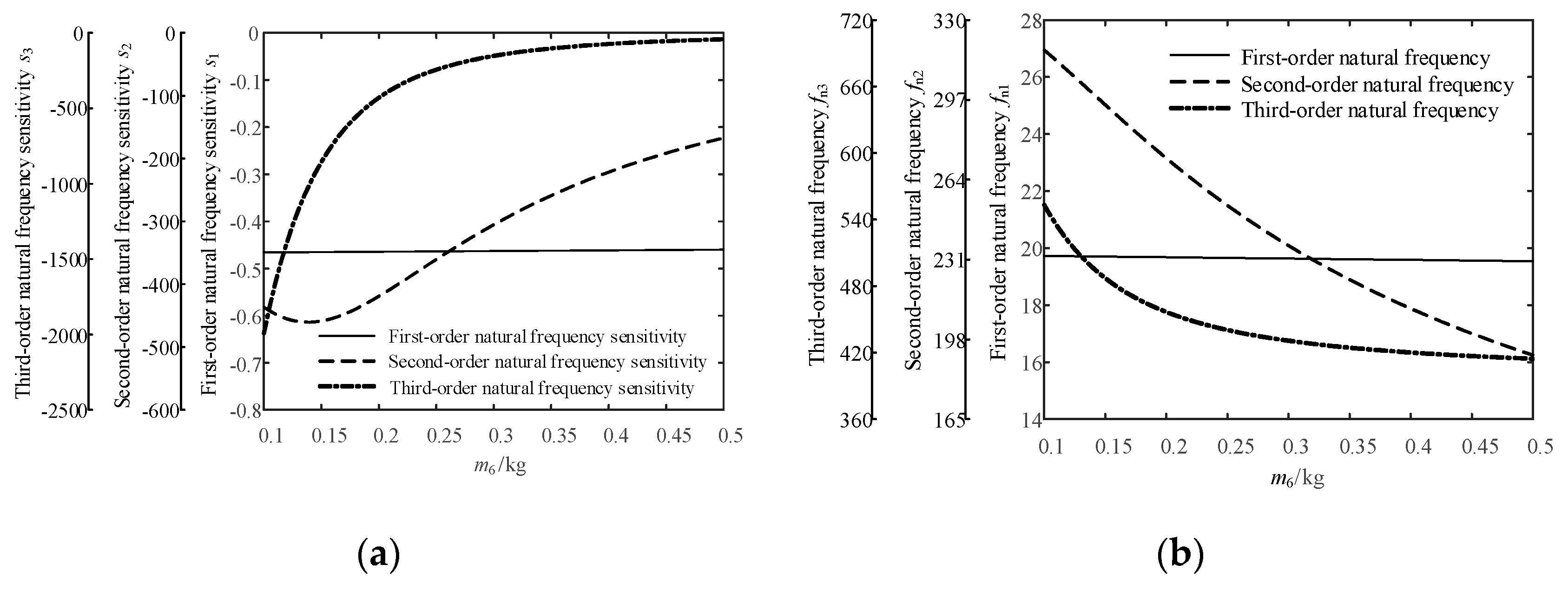
4.6. Sensitivity Analysis of the Natural Frequency of the Jet System to the Mass of the Spray Core

Let the initial gas content of the fluid be 0.02 and the fluid pressure be 0.6 MPa. When the mass of the spray core is in the range of 0.1–0.5 kg, the variation law of the first three natural frequencies and their sensitivities of the jet system with m 6 is shown in Figure 14.
From Figure 14, the following laws can be summarized:
(1)
With the increase in the mass of the spray core, the first-order natural frequency sensitivity of the jet system increases slightly in the process, but it can be regarded as basically unchanged due to the small increase. The absolute value of the sensitivity is small and negative. In the variation of the natural frequency, the first-order natural frequency decreases slightly from 19.73 Hz to 19.54 Hz with the increase in the mass of the spray core.
(2)
With the increase in the mass of the spray core, the second-order natural frequency sensitivity of the jet system is negative, and its absolute value increases first and then decreases. Therefore, the second-order natural frequency of the jet system appears to decrease monotonically with the increase in the mass of the spray core, and the rate of decline increases slightly first and then decreases gradually.
(3)
With the increase in the mass of the spray core, the third-order natural frequency sensitivity of the jet system is negative, and its absolute value decreases gradually. Therefore, the third-order natural frequency of the jet system decreases with the increase in the mass of the spray core. The rate of decline decreases gradually and tends to zero eventually.
In summary, the change in the mass of the spray core has a rare effect on the first-order natural frequency of the jet system, but the second-order and third-order natural frequencies of the jet system decrease gradually with the increase in the mass of the spray core.

4.7. Sensitivity Analysis of the Natural Frequency of the Jet System to the Stiffness of the Spring in the Gun Head

Let the initial gas content of the fluid be 0.02 and the fluid pressure be 0.6 MPa. When the stiffness of the spring in the gun head is in the range of 10–30 kN/m, the variation law of the first three natural frequencies and their sensitivities of the jet system with k 5 is shown in Figure 15.
It can be seen from Figure 15 that as the stiffness of the spring in the adaptive gun head increases, the first-order and second-order natural frequency sensitivities of the jet system monotonically decrease, the third-order natural frequency sensitivity monotonically increases, and their values are all positive. Corresponding to the change of natural frequency sensitivity of each order, the first three natural frequencies of the jet system gradually increase with the increase in spring stiffness, and the growth rate is small, which indicates that the spring stiffness of the gun head has little effect on the first three natural frequencies of the jet system and their sensitivities.

5. Experimental Verification

In order to verify the accuracy of the modal analysis of the jet system, a platform for the dynamic experiment of the fire-fighting jet system with adaptive gun head was built. The modal test of the working jet system was carried out by the hammering method. The experiment platform is shown in Figure 16. The experimental parameters are consistent with the parameters shown in Table 1.
The fast Fourier transform was used to analyze the acceleration signal output from the jet system in the frequency domain. The amplitude-frequency characteristics of the acceleration signal of the jet system under the action of the fluid self-pulsation excitation and the hammer step excitation are shown in Figure 17. The coordinate of point A in the Figure 17 is (19.5, 0.1438) and the coordinate of point B is (46.8, 0.1588).
It can be seen from Figure 17 that the jet system has relatively obvious peaks at the frequencies of 19.5 Hz and 46.8 Hz, of which 46.8 Hz is the axial frequency of the centrifugal pump for the experimental system (2800 RPM) and 19.5 Hz is the first-order natural frequency of the jet system in the experiment. At the same time, due to the influence of fluid turbulence in the fire-fighting monitor, the amplitude-frequency curve superimposes the amplitude-frequency characteristics of white noise, which increases the difficulty of frequency spectrum recognition. Therefore, other order natural frequencies of the jet system cannot be determined experimentally. The experimental data and theoretical value of the first-order natural frequency of the jet system are shown in Table 4.
It can be seen from Table 4 that the theoretical first-order natural frequency is very close to the experimental data, and the error is only 0.51%, which verifies the accuracy of the proposed dynamic model of the fire-fighting jet system with the adaptive gun head.

6. Conclusions

(1)
Considering the fluid-structure interaction and discrete-continuous coupling characteristics of the fire-fighting jet system with the adaptive gun head, the dynamic model and equations of the fire-fighting jet system with adaptive gun head were established based on the lumped parameter method. The sensitivity calculation formulas of the natural frequency of the jet system to typical design parameters were derived.
(2)
The modal analysis of the jet system was carried out, and the natural frequencies of the orders and the corresponding modal vectors under given conditions were obtained. The sensitivity analysis of the jet system was carried out, and the variation law of the first three natural frequencies and their sensitivities of the jet system to typical design parameters was revealed. Among the parameters involved, the first three natural frequencies of the jet system were the most sensitive to the change in the mass of fluid unit 2 in the range of a certain initial gas content.
(3)
The platform for the dynamic experiment of the fire-fighting jet system with the adaptive gun head was built, and the modal experiment of the jet system was carried out. There was only a 0.51% error between the value of the first-order natural frequency of the jet system determined by the modal experiment and the theoretical one determined by the analytical method, showing that good agreement with the first-order natural frequency of the jet system was found.

Author Contributions

Conceptualization, X.Y. and C.W.; methodology, X.Z.; investigation, X.Z. and C.W.; writing—original draft preparation, X.Y.; writing—review and editing, C.W. and X.Z.; supervision, L.Z. and Y.Z.

Funding

This work is funded by the National Natural Science Foundation of China (No. 51805468, 51805214), Natural Science Foundation of Hebei Province (No. E2017203129), Open Foundation of the State Key Laboratory of Fluid Power and Mechatronic Systems (No. GZKF-201820), Basic Research Special Funding Project of Yanshan University (No. 16LGB001), and China Postdoctoral Science Foundation (No. 2019M651722). The authors would also like to thank the reviewers for their valuable suggestions and comments.

Conflicts of Interest

The authors declare no conflicts of interest.

References

  1. Zhu, J.; Li, W.; Lin, D.; Zhao, G. Study on water jet trajectory model of fire monitor based on simulation and experiment. Fire Technol. 2018, 55, 773–787. [Google Scholar] [CrossRef]
  2. Hu, G.L.; Chen, W.G.; Gao, Z.G. Flow analysis of spray jet and direct jet nozzle for fire water monitor. Adv. Mater. Res. 2010, 139–141, 913–916. [Google Scholar] [CrossRef]
  3. Bhende, A.R.; Kadu, P.S. Behavioral analysis of hydraulically driven fire fighting water monitor trailer subjected to type of fire & ways of its fire protection. In Proceedings of the 2009 Second International Conference on Emerging Trends in Engineering & Technology, Nagpur, India, 16–18 December 2009. [Google Scholar]
  4. Berner, O. A volume and pressure controlling spill valve equipped for removal of excess aesthetic gas. Acta Anaesthesiol. Scand. 2010, 16, 252–258. [Google Scholar] [CrossRef]
  5. Qian, J.Y.; Chen, M.R.; Liu, X.L.; Jin, Z.J. A numerical investigation of the flow of nanofluids through a micro tesla valve. J. Zhejiang Univ. Sci. A 2019, 20, 50–60. [Google Scholar] [CrossRef]
  6. Qian, J.Y.; Gao, Z.X.; Liu, B.Z.; Jin, Z.J. Parametric study on fluid dynamics of pilot-control angle globe valve. ASME J. Fluids Eng. 2018, 140, 111103. [Google Scholar] [CrossRef]
  7. Salacinska, K.; El Serafy, G.Y.; Los, F.J.; Blauw, A. Sensitivity analysis of the two dimensional application of the Generic Ecological Model (GEM) to algal bloom prediction in the North Sea. Ecol. Model. 2010, 221, 178–190. [Google Scholar] [CrossRef]
  8. Gallivan, S. Challenging the role of calibration, validation and sensitivity analysis in relation to models of health care processes. Health Care Manag. Sci. 2008, 11, 208–213. [Google Scholar] [CrossRef] [PubMed]
  9. Zhu, Y.; Qian, P.; Tang, S.; Jiang, W.; Li, W.; Zhao, J. Amplitude-frequency characteristics analysis for vertical vibration of hydraulic AGC system under nonlinear action. AIP Adv. 2019, 9, 035019. [Google Scholar] [CrossRef] [Green Version]
  10. Zhu, Y.; Tang, S.; Wang, C.; Jiang, W.; Yuan, X.; Lei, Y. Bifurcation characteristic research on the load vertical vibration of a hydraulic automatic gauge control system. Processes 2019, 7, 718. [Google Scholar] [CrossRef]
  11. Zhu, Y.; Tang, S.; Quan, L.; Jiang, W.; Zhou, L. Extraction method for signal effective component based on extreme-point symmetric mode decomposition and Kullback-Leibler divergence. J. Braz. Soc. Mech. Sci. Eng. 2019, 41, 100. [Google Scholar] [CrossRef]
  12. Félix, G.; Ancheyta, J.; Trejo, F. Sensitivity analysis of kinetic parameters for heavy oil hydrocracking. Fuel 2019, 241, 836–844. [Google Scholar] [CrossRef]
  13. Prieur, C.; Viry, L.; Blayo, E.; Brankart, J.-M. A global sensitivity analysis approach for marine biogeochemical modeling. Ocean Model. 2019, 139, 101402. [Google Scholar] [CrossRef] [Green Version]
  14. Guo, R.; Hu, Y.; Liu, M.Z.; Heiselberg, P. Influence of design parameters on the night ventilation performance in office buildings based on sensitivity analysis. Sustain. Cities Soc. 2019, 50, 101661. [Google Scholar] [CrossRef]
  15. Gunay, H.B.; Ouf, M.; Newsham, G.; O’Brien, W. Sensitivity analysis and optimization of building operations. Energy Build. 2019, 199, 164–175. [Google Scholar] [CrossRef]
  16. Dong, F.; Li, J.Y.; Zhang, S.N.; Wang, Y.; Sun, Z.Y. Sensitivity analysis and spatial-temporal heterogeneity of CO2 emission intensity: Evidence from China. Resour. Conserv. Recycl. 2019, 150, 104398. [Google Scholar] [CrossRef]
  17. Rezaie, F.; Bayat, M.A.; Farnam, S.M. Sensitivity analysis of pre-stressed concrete sleepers for longitudinal crack prorogation effective factors. Eng. Fail. Anal. 2016, 66, 385–397. [Google Scholar] [CrossRef]
  18. Tashakor, S.; Afsari, A.; Hashemi-Tilehnoee, M. Sensitivity analysis of thermal-hydraulic parameters to study the corrosion intensity in nuclear power plant steam generators. Nucl. Eng. Technol. 2019, 51, 394–401. [Google Scholar] [CrossRef]
  19. Cao, J.K.; Ding, S.T. Sensitivity analysis for safety design verification of general aviation reciprocating aircraft engine. Chin. J. Aeronaut. 2012, 25, 675–680. [Google Scholar] [CrossRef]
  20. He, X.; Jiao, W.; Wang, C.; Cao, W. Influence of surface roughness on the pump performance based on Computational Fluid Dynamics. IEEE Access 2019, 7, 105331–105341. [Google Scholar] [CrossRef]
  21. Wang, C.; Hu, B.; Zhu, Y.; Wang, X.; Luo, C.; Cheng, L. Numerical study on the gas-water two-phase flow in the self-priming process of self-priming centrifugal pump. Processes 2019, 7, 330. [Google Scholar] [CrossRef]
  22. Jia, W.H.; Yin, C.B.; Hao, F.; Li, G.; Fan, X.Z. Dynamic characteristics and stability analysis of conical relief valve. Mechanika 2019, 25, 25–31. [Google Scholar] [CrossRef]
  23. Zhang, K.Q.; Karney, B.W.; Mcpherson, D.L. Pressure-relief valve selection and transient pressure control. Am. Water Works Assoc. 2008, 100, 62–69. [Google Scholar] [CrossRef]
  24. Zhang, J.; Xia, S.; Ye, S.; Xu, B.; Song, W.; Zhu, S.; Xiang, J. Experimental investigation on the noise reduction of an axial piston pump using free-layer damping material treatment. Appl. Acoust. 2018, 139, 1–7. [Google Scholar] [CrossRef]
  25. Ye, S.; Zhang, J.; Xu, B.; Zhu, S. Theoretical investigation of the contributions of the excitation forces to the vibration of an axial piston pump. Mech. Syst. Signal Process. 2019, 129, 201–217. [Google Scholar] [CrossRef]
  26. Zhu, Y.; Tang, S.; Wang, C.; Jiang, W.; Zhao, J.; Li, G. Absolute stability condition derivation for position closed-loop system in hydraulic automatic gauge control. Processes 2019, 7, 766. [Google Scholar] [CrossRef]
  27. Imagine, S.A. HYD advanced fluid properties. Technical Bulletin. 2007, 117, 7. [Google Scholar]
Figure 1. Structure of a traditional diversion gun head. 1. Joint; 2. Nut; 3. Regulator; 4. Gasket; 5. Enclosure; 6. Ring; 7. Outer nozzle; 8. Inner nozzle; 9. Spray core; 10. End cap; 11. Core rod.
Processes 07 00808 g001
Figure 2. Structure of the new adaptive gun head. 1. Joint; 2. Nut; 3. Regulator; 4. Gasket; 5. Enclosure; 6. Ring; 7. Outer nozzle; 8. Inner nozzle; 9. Spray core; 10. End cap; 11. Core rod; 12. Spring; 13. Core sleeve; 14. Seal ring.
Processes 07 00808 g002
Figure 3. Structure of a fire-fighting jet system with the adaptive gun head.
Processes 07 00808 g003
Figure 4. Interaction between the units in the fire-fighting jet system with the adaptive gun head.
Processes 07 00808 g004
Figure 5. Dynamic model of the fire-fighting jet system with the adaptive gun head.
Processes 07 00808 g005
Figure 6. The variation law of the first three natural frequencies and their sensitivities of the jet system under a different initial gas content of the fluid with the mass of fluid unit 1. (a) Variation law of natural frequency sensitivity. (b) Variation law of natural frequency.
Processes 07 00808 g006
Figure 7. The variation law of the first three natural frequencies and their sensitivities of the jet system under a different pressure of the fluid with the mass of fluid unit 1. (a) Variation law of natural frequency sensitivity. (b) Variation law of natural frequency.
Processes 07 00808 g007
Figure 8. The variation law of the first three natural frequencies and their sensitivities of the jet system under a different initial gas content of the fluid with the stiffness of fluid unit 1. (a) Variation law of natural frequency sensitivity. (b) Variation law of natural frequency.
Processes 07 00808 g008
Figure 9. The variation law of the first three natural frequencies and their sensitivities of the jet system under a different pressure of the fluid with the stiffness of fluid unit 1. (a) Variation law of natural frequency sensitivity. (b) Variation law of natural frequency.
Processes 07 00808 g009
Figure 10. The variation law of the first three natural frequencies and their sensitivities of the jet system under a different initial gas content of fluid with the mass of fluid unit 2. (a) Variation law of natural frequency sensitivity. (b) Variation law of natural frequency.
Processes 07 00808 g010
Figure 11. The variation law of the first three natural frequencies and their sensitivities of the jet system under a different pressure of the fluid with the mass of fluid unit 2. (a) Variation law of natural frequency sensitivity. (b) Variation law of natural frequency.
Processes 07 00808 g011
Figure 12. The variation law of the first three natural frequencies and their sensitivities of the jet system under a different initial gas content of fluid with the stiffness of fluid unit 2. (a) Variation law of natural frequency sensitivity. (b) Variation law of natural frequency.
Processes 07 00808 g012
Figure 13. The variation law of the first three natural frequencies and their sensitivities of the jet system under a different pressure of the fluid with the stiffness of fluid unit 2. (a) Variation law of natural frequency sensitivity. (b) Variation law of natural frequency.
Processes 07 00808 g013
Figure 14. The variation law of the first three natural frequencies and their sensitivities of the jet system with the mass of the spray core. (a) Variation law of natural frequency sensitivity. (b) Variation law of natural frequency.
Processes 07 00808 g014
Figure 15. The variation law of the first three natural frequencies and their sensitivities of the jet system with the stiffness of the spring in the gun head. (a) Variation law of natural frequency sensitivity. (b) Variation law of natural frequency.
Processes 07 00808 g015
Figure 16. Platform for dynamic experiment of the fire-fighting jet system with the adaptive gun head. (a) Prototype of gun head. (b) Experimental equipment.
Processes 07 00808 g016
Figure 17. Amplitude-frequency characteristic curve of the fire-fighting jet system with the adaptive gun head.
Processes 07 00808 g017
Table 1. Data for each segment size of the fluid units.
Fluid UnitSegmentationEquivalent Stiffness of Fluid Unit SubsectionAverage Area of Flow Cross Section Sai/(mm2)Axial Length of the Fluid Domain Li/(mm)
Fluid unit 1l1kf1162211534.6
l2kf12620038
l3kf13320039
l4kf14380035.5
l5kf15440038
l6kf16370064
Fluid unit 2l1’kf21’30046.1
l2’kf22’80011
l3’kf23’280040.5
Table 2. Design parameters of the jet system.
Parameter NameParameter SymbolUnitValue
Mass of core rodmkg0.0354
Mass of end capmdkg0.1177
Mass of spray corem6kg0.3163
Mass of Fluid unit 1m7kg16.4593
Mass of Fluid unit 2m5kg0.1362
Stiffness of discrete unit of the core rodk1kN/m333,460
Equivalent stiffness 1 of fluidkf1kN/m354.05
Equivalent stiffness 2 of fluidkf2kN/m424.07
Equivalent stiffness 3 of fluidkf3kN/m424.07
Stiffness of the spring in the gun headk5kN/m18
Fluid pressurepMPa0.6
Initial gas content of fluidx%2
Bulk elastic modulus of fluidBfMPa161.1432
TemperatureTK293
Table 3. Natural frequencies and mode shapes of the jet system.
OrderFirst-OrderSecond-OrderThird-OrderFourth-OrderFifth-OrderSixth-OrderSeventh-Order
Natural frequency fni/Hzfn1fn2fn3fn4fn5fn6fn7
19.6230.8427.4404024,276.943,90657,146.6
Principal mode of each mode Φni0.00040.0010.00130.2610.72311−0.7044
0.00090.0020.00250.51761−0.01861
0.00150.0030.00380.76530.6597−0.9997−0.7153
0.00190.00410.0051−0.08770.03720.0155
0.35490.75781−0.0049000
0.70621−0.32050.0001000
1−0.02520.00230000
Table 4. Comparison between experimental data and theoretical value.
Natural FrequencyExperimental DataTheoretical ValueError
The first-order natural frequency19.5 Hz19.6 Hz0.51%

