1. Problem Description
Natural gas usually contains water vapor when it leaves the reservoir. When the pressure and temperature of natural gas change, water vapor easily forms the hydrate. Local accumulation of hydrate will restrict the flow rate of natural gas in the pipeline, increase pressure drop, reduce gas transmission capacity, and even block the pipeline seriously, leading to gas interruption. At the same time, moisture in natural gas is also the main factor causing corrosion of equipment, instruments, and pipelines. Therefore, in order to ensure the normal operation of pipelines, natural gas must be dehydrated. The GB50251 standard [
1] states that the water dew point of natural gas must be 5 °C lower than the lowest temperature along the various sections of the gas pipeline.
The conventional natural gas dehydration processes in oil and gas fields are solvent absorption and solid desiccant adsorption. At present, glycol absorption dehydration and molecular sieve adsorption dehydration are widely used. The difference between the two methods is the depth of dehydration. Triethylene glycol (TEG) dehydration technology is the most widely used in the natural gas dehydration process. Usually, the main equipment of a TEG dehydration system includes a TEG absorption tower, TEG heating furnace, TEG regeneration tower, TEG circulating pump, and so on. Although the process is widely used, its shortcomings cannot be ignored: (1) When the regeneration tower is in normal production, some of the light hydrocarbons are inevitably contained in the water vapor discharged from the top of the tower. This part of the light hydrocarbons will be directly discharged into the atmosphere, causing pollution to the surrounding atmospheric environment and increased risk of fire accidents. (2) A TEG heating furnace generally uses a natural gas open flame heating furnace, and the decomposition temperature of TEG is 206 °C, so the burner performance directly affects the thermal efficiency of the furnace and easily causes damage to the furnace tube. (3) The tower equipment covers a large area, has low mass transfer efficiency, and limited treatment capacity [
2].
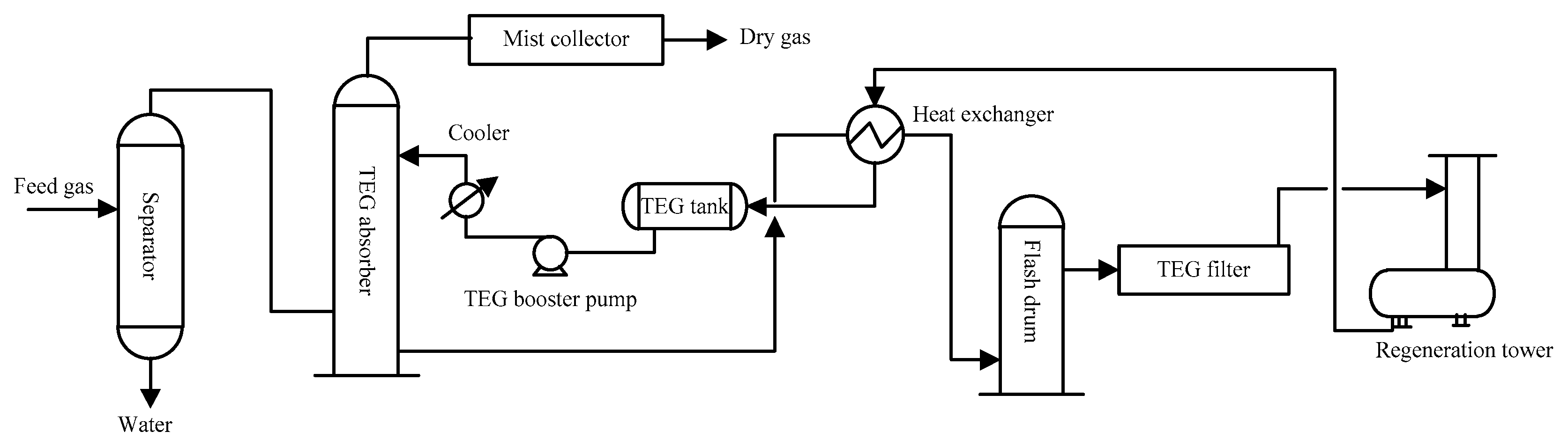
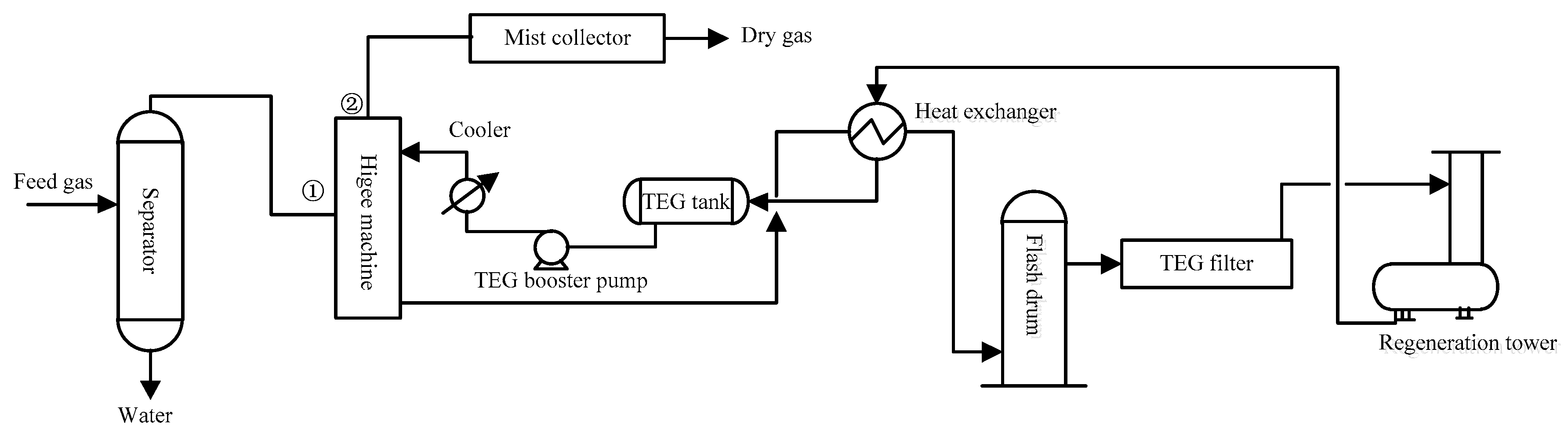
At present, in the offshore gas field production operation, due to the lower control index requirements of the natural gas dew point, the TEG dehydration process is generally used. The conventional TEG dehydration process is shown in
Figure 1. However, due to site constraints, the size of the absorption tower is generally relatively small. In the case of fluctuation of raw gas and large gas production, it is easy to cause large losses of TEG and tower flooding events [
3]. With the continuous development of offshore oil and gas fields, the field conditions have changed. The instability of the traditional dehydration process results in the corrosion of platform equipment and pipelines. Therefore, it is not suitable to directly adopt the conventional triglyceride dehydration process and equipment for offshore platforms with a tight area and limited weight.
Supergravity technology is a new generation of chemical separation technology [
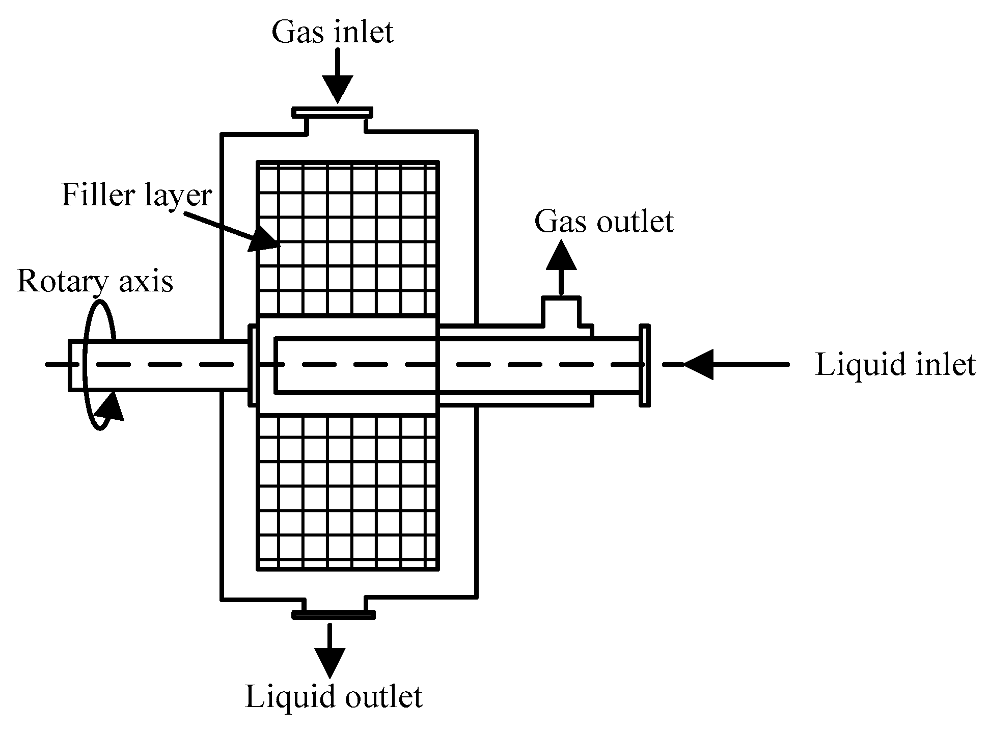
4]. Although developed in the 1980s, the high gravity machine (Higee) is a rapidly developing multi-media contact reaction equipment. Compared with the tower equipment, the mass transfer coefficient is one to three orders of magnitude higher. The size and weight of the equipment is only a few percent of the tower equipment. Furthermore, the footprint is greatly reduced, which is very suitable for offshore platforms. This paper takes the TEG dehydration system of an offshore platform as an example to verify the feasibility of replacing the original tower equipment with the super gravity equipment. According to field research, the TEG dehydration system of the offshore platform has the following specific problems:
(1) Gas composition changes
During the mining process, the composition of natural gas changes (
Table 1), and the composition of C
3+ increases, so that excessive light hydrocarbons are mixed with TEG, causing TEG to foam and affect the dehydration effect.
(2) Insufficient operation capacity of dehydration tower
The TEG dehydration tower has a diameter of only 762 mm and a treatment capacity of 115 × 104 m3/d under full load conditions. Now it needs to process 160 × 104 m3/d of natural gas, which puts tremendous pressure on the operation of the tower equipment.
(3) Dew point is unqualified
Due to the increase in natural gas flow, the dew point is difficult to meet the requirements. In 2007, the dew point requirement was −24 °C, and in 2011 the dew point was 0 °C.
Therefore, it has been difficult to meet the requirements of the offshore platform using the conventional TEG dehydration system.
2. Literature Review
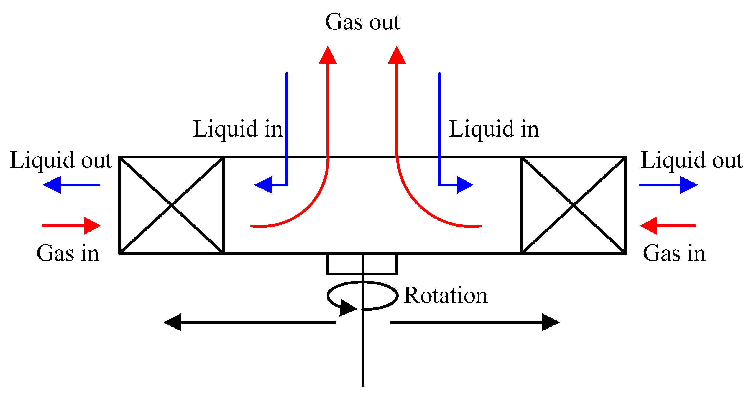
In supergravity technology, a rotating annular porous packed bed is used instead of a vertical stationary tower, so that gas–liquid contacts fully in the rotating packed bed. The process of mass transfer and heat transfer is strengthened by the high dispersion of the liquid phase, rapid surface renewal, and strong perturbation of phase interface in the Higee. Compared with the tower equipment, the volume mass transfer coefficient is one to three orders of magnitude higher. The volume and weight of the equipment is only a few percent of the tower equipment. It is called “the transistor of the chemical industry”. The principle of the Higee is shown in
Figure 2 [
5].
At present, the research of high gravity fluidized bed technology focuses on the application of different materials in the drying process, including the initial fluidization behavior of different materials and the study of mass transfer and heat transfer rate in the drying process. Qi et al. [
6] used high gravity equipment to desulfurize, and analyzed the influence of rotational speed, temperature, and other factors on desulfurization rate. The results showed that the desulfurization rate of this method was higher than 99% and proved that the equipment had the characteristics of high efficiency and small volume compared with traditional tower equipment. Xing et al. [
7] studied the removal efficiency of carbon dioxide from flue gas of boilers by using a high gravity rotating bed. The effects of absorption liquid concentration and liquid flow rate on the absorption efficiency were investigated. It was found that the removal efficiency of carbon dioxide could reach 85.81%, which was 25% higher than that of tower equipment. Wang [
8] used the mixture of air and sulfur dioxide to simulate the flue gas and studied the desulfurization in a rotating packed bed by double alkali method. The optimum technological conditions for the absorption of sulfur dioxide by sodium hydroxide solution in a rotating packed bed were determined. Liu et al. [
9] used water, calcium hydroxide, and magnesium hydroxide suspension as absorbents to carry out flue gas desulfurization experiments in a rotating packed bed. The effects of absorbent concentration, flow rate of absorbent, rotating speed of rotating packed bed, and concentration of sulfur dioxide in inlet gas on mass transfer rate were investigated. The effects of various factors on mass transfer rate of sulfur dioxide and their causes were analyzed. The results show that under the known experimental conditions, the reaction rate of sulfur dioxide absorption by alkaline liquids is three to four times that of water. At the same time, the reaction rate of sulfur dioxide can be greatly increased by increasing the flow rate of alkaline liquids and the rotating speed of the high gravity rotating bed.
High gravity technology can be used not only in desulfurization and decarbonization, but also in denitrification and ammonia absorption industries. However, this technique is rarely used in TEG dehydration systems. A new process for gas drying based on the supergravity technology applied to the offshore platform is proposed, in which the high-gravity machine replaces the absorber unit of the conventional TEG dehydration device. Consequently, the retention time of the absorbent is reduced and the apparatus like the holding tank downsized. The developed process is a low-cost method for water removal from the natural gas and it is significant progress to apply the supergravity technology to gas dehydration.
4. Laboratory Experiment
4.1. Experiment Conditions
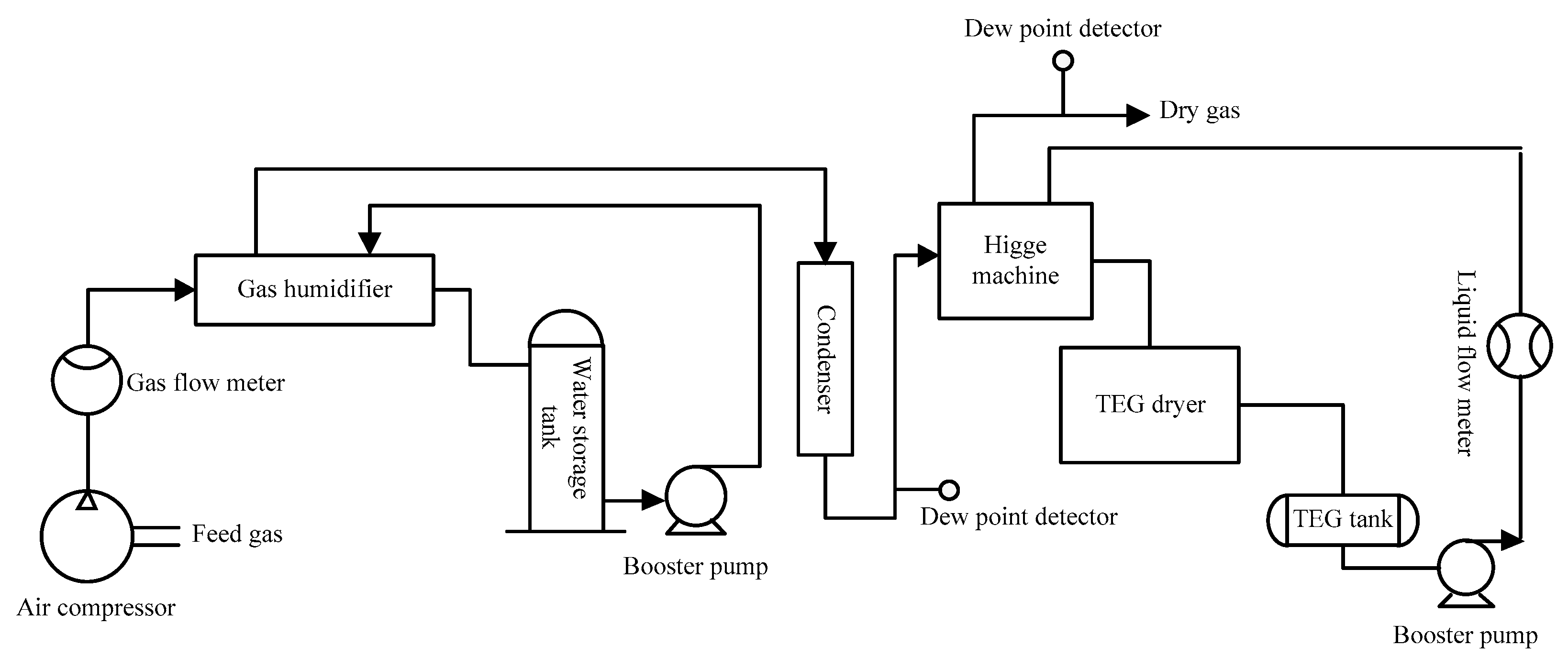
In order to verify the feasibility of the proposed method, a laboratory experiment was used. The flow chart of the experiment is shown in
Figure 4. The experiment can be divided into five systems: TEG regeneration system, TEG dehydration system, dew point control system of the feed gas, detection system, and Higee. The description of each system is shown in
Table 2.
In the TEG dehydration experiment, the influence of the TEG flow rate, the super-gravity packed bed rotation speed, and the gas flow rate on the air dew point were analyzed. The experimental conditions are shown in
Table 3.
4.2. Conventional Analysis
(1) TEG flow rate
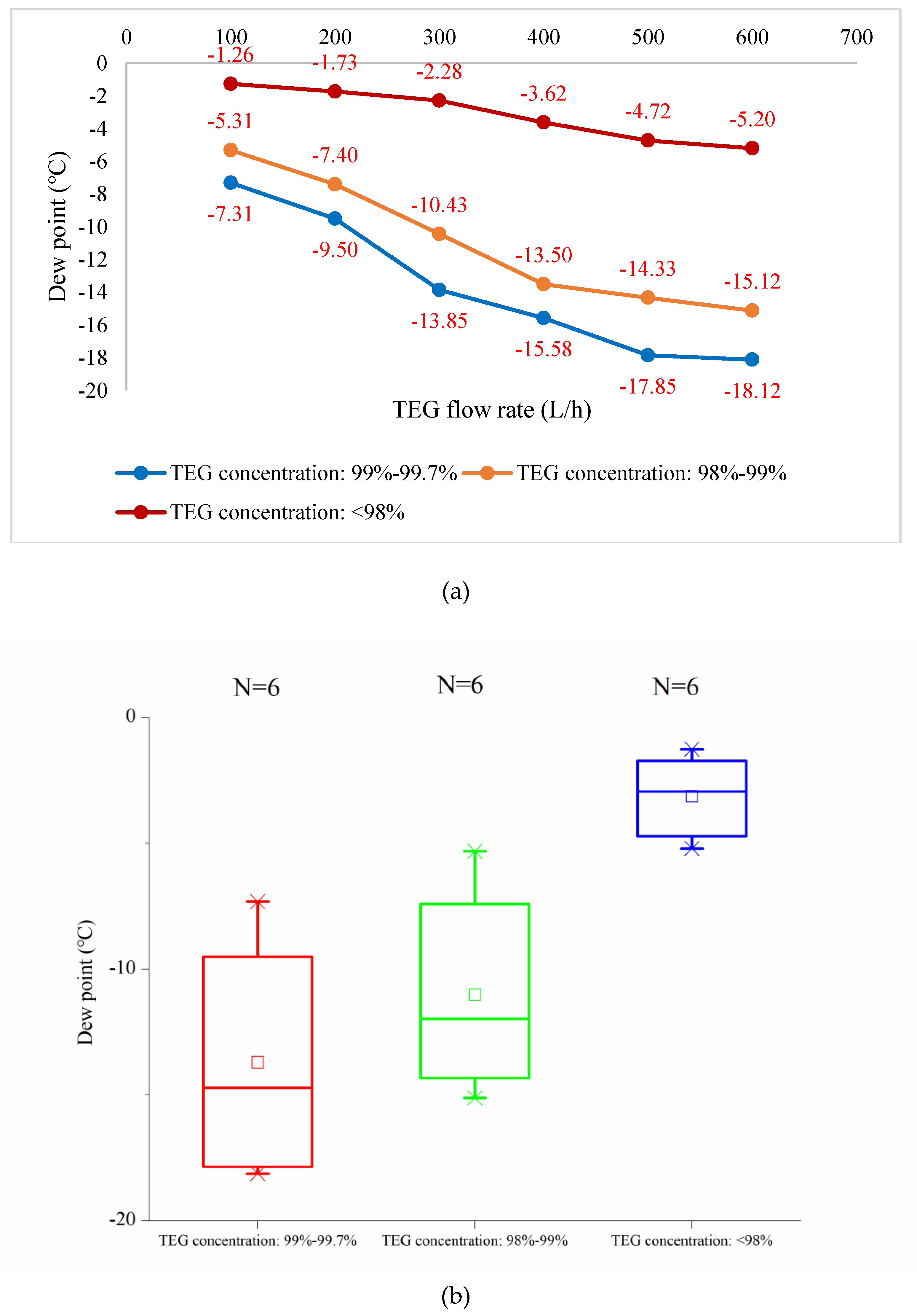
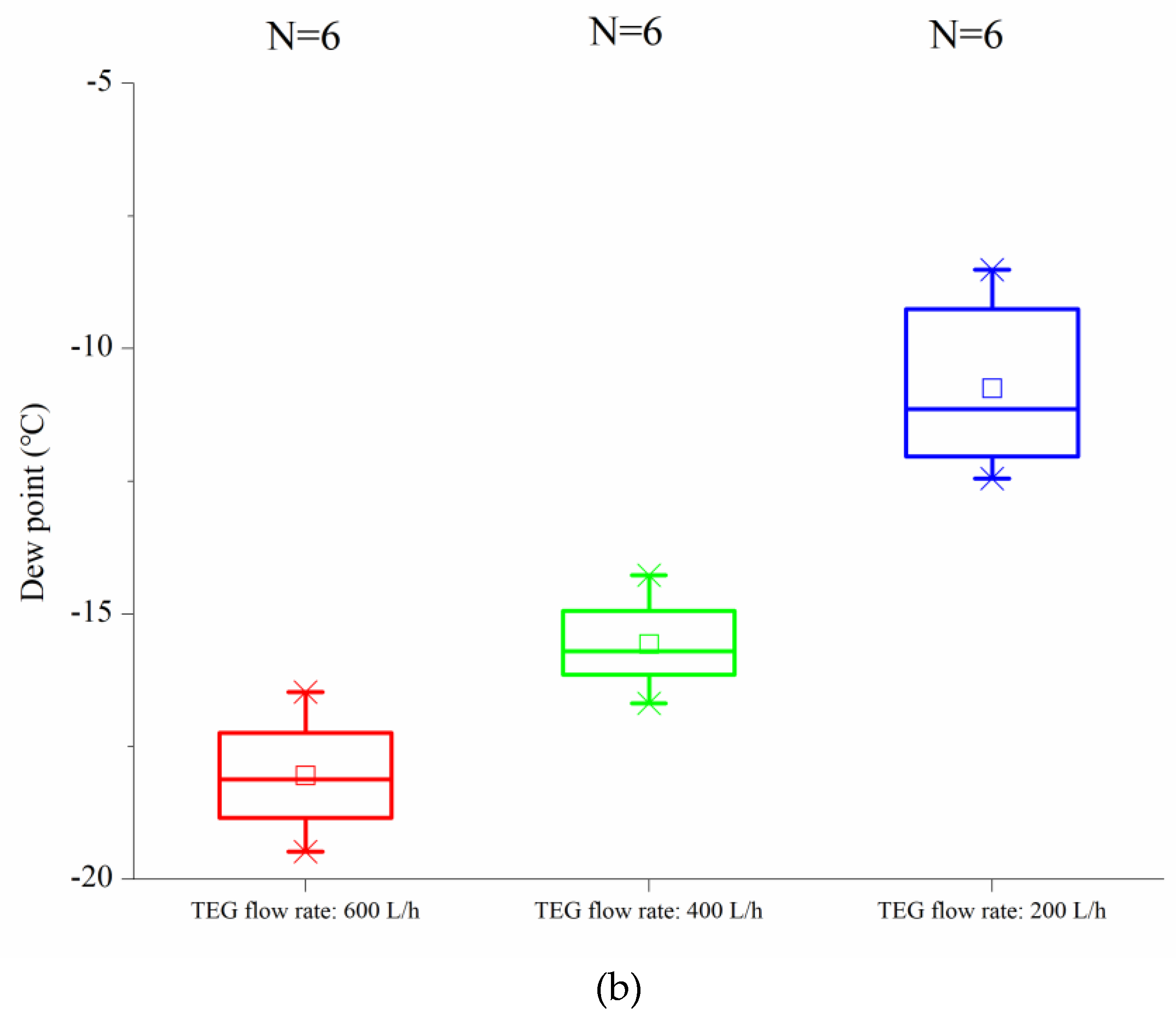
As can be seen from
Figure 5, the influence of TEG flow on dew point was very significant. Under a certain rotational speed, dew point decreased with the increase of TEG flow rate. This was because the increase in flow rate increased the chance of gas–liquid contact and increased the impetus of mass transfer. In addition, the absorbent liquid rotated with the rotor and achieved a higher tangential velocity when moving along the packing layer. The liquid was dispersed into small droplets, liquid film or liquid filament in the packing layer, which reduced the mass transfer resistance of the gas–liquid phase and improved the mass transfer coefficient.
The effect of concentration of TEG solution on dew point was also obvious. The effect of mass transfer at high concentration was much stronger than that at low concentration. The water content in poor solutions should be less than 1%, and the water content in rich solutions should not be more than 5%–6%. Therefore, the concentration of poor TEG solution was between 98% and 99.5%, and that of rich TEG solution was between 93% and 97%.
When the flow rate was less than 400 L/h, the dew point decreased very little; even if the concentration of TEG was higher, the effect was not ideal. The main reason was that when the flow rate was too low, the pressure head of the TEG solution was low. After entering the Higee, the liquid could not flow out in a jet but flowed down at a low speed. In this way, the liquid could not all enter the high-speed rotating wire mesh packing; on the contrary, it increased the mass transfer resistance between the gas phase and liquid phase and reduced the absorption of TEG. When the flow rate was above 400 L/h, the dynamic pressure head of TEG was large enough. However, when the flow rate of TEG was too large because the viscosity of TEG was too high, the flow requirement was higher and the increased power undoubtedly increased the consumption of electricity. Therefore, it was very important to find out the optimal liquid flow rate for industrial implementation and operation.
(2) Super-gravity packed bed rotation speed
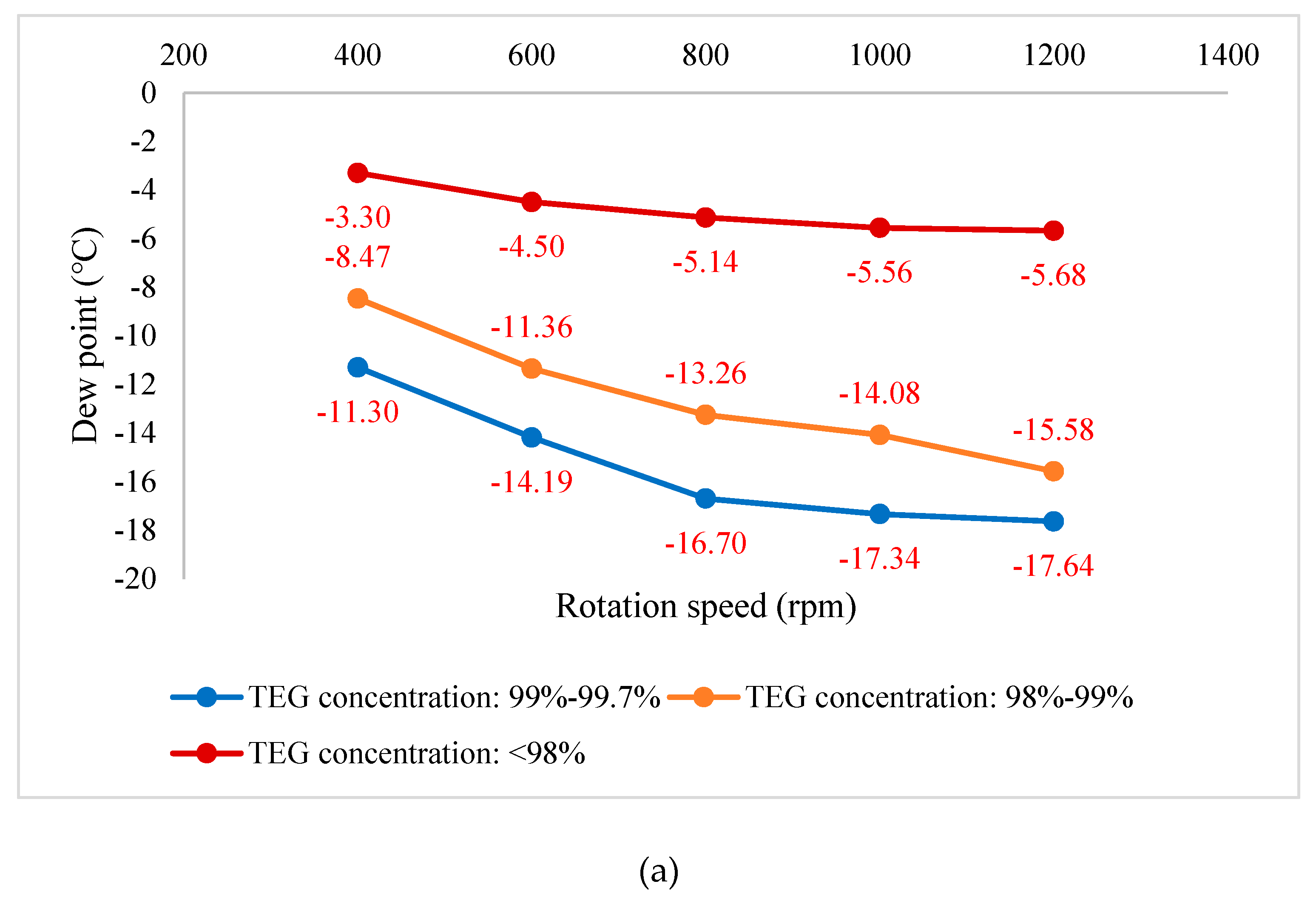
As shown in
Figure 6, when TEG flow rate was constant, the mass transfer coefficient increased with the increase of rotating speed of the rotating bed rotor. This was because it accelerated the movement of liquid in the packing layer, increased the turbulence of liquid, enlarged the gas–liquid contact area, enlarged the mass transfer coefficient, and decreased the dew point of gas significantly. When the rotational speed exceeded a certain range, the increase of rotational speed made the gas–liquid contact time less, and the influence of rotational speed on mass transfer coefficient was not obvious, so the change of dew point tended to be stable. Considering comprehensively, the rotating speed of the rotating bed of the Higee was determined to be greater than 800 rpm.
(3) Gas flow rate
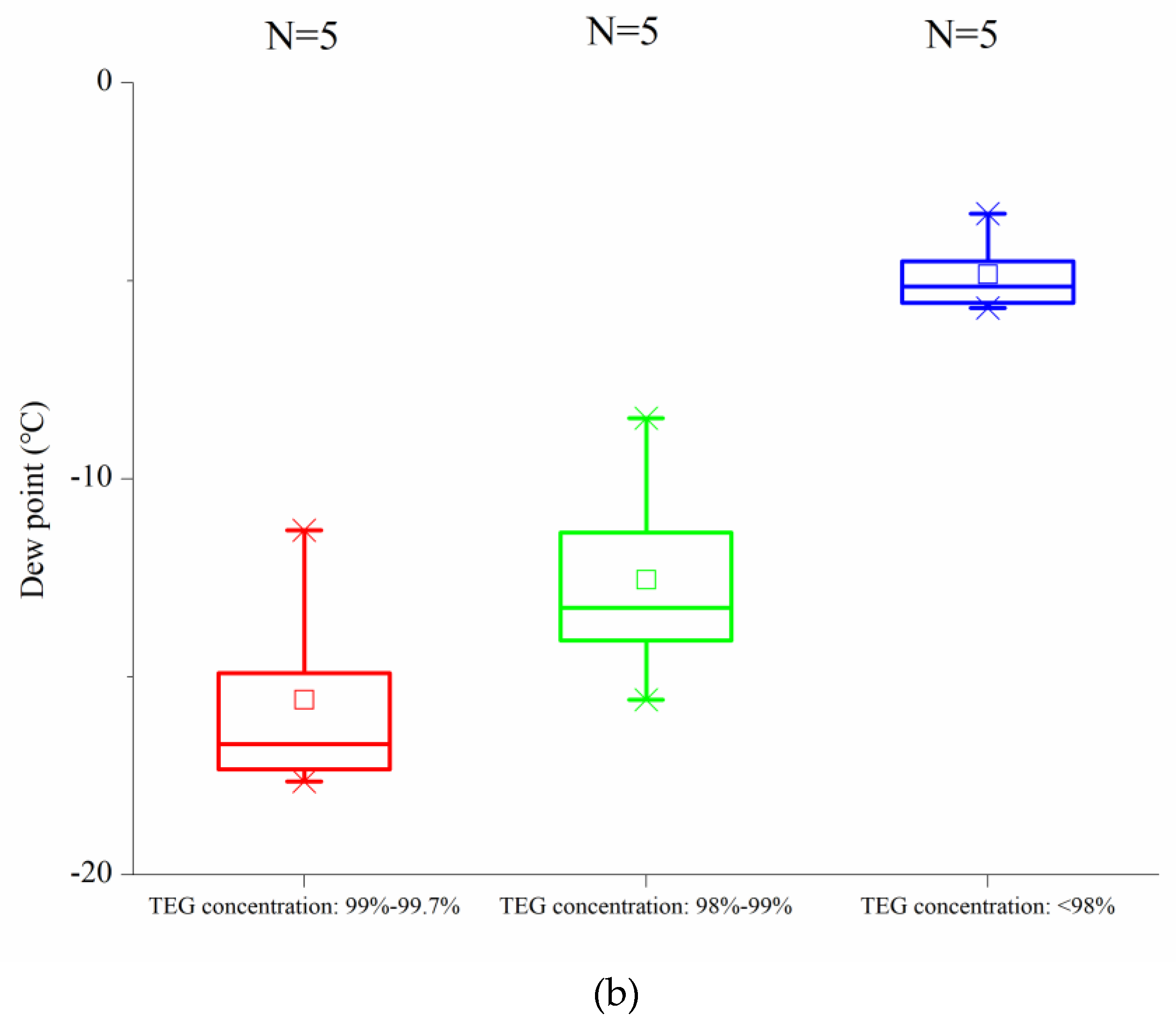
Figure 7 shows that when TEG flow rate was greater than 400 L/h, the gas flow rate had little effect on dew point, but when TEG flow rate was 200 L/h, the gas flow rate had a significant effect on dew point, and dew point increased with the increase of gas flow rate. When the rotational speed and the water content in the gas flow were constant, the increase of gas flow rate had little effect on dew point under the large TEG flow rate. Under the small TEG flow rate, the dew point increased with the increase of gas flow rate, and the effect was significant.
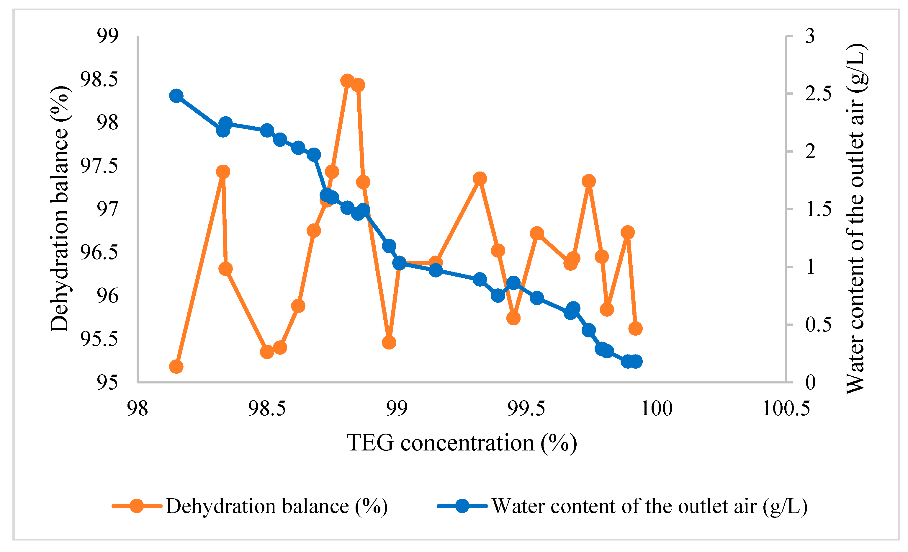
(4) Dehydration balance
Based on the above experimental results, the dehydration balance of the rotating packed bed in the modified TEG dehydration process was defined to evaluate its dehydration performance. Dehydration balance is defined as:
where
α is the dehydration balance;
Pv is the saturated vapor pressure of the poor TEG solution; and
Ps is the saturated vapor pressure of the gas at the outlet.
Figure 8 shows the dehydration balance obtained from a set of experiments. The experimental conditions were as follows: the rotating speed of the rotating bed rotor was 1000 rpm, the liquid–gas ratio was 1:20, the temperature was 20 °C, and the water content of inlet air was 13 g/L. It can be seen that the dehydration balance of the dehydration by using rotating packed bed was above 95%, which was much higher than the dehydration balance of about 80% of the traditional tower dehydration equipment. It is fully explained that the dehydration performance of the rotating packed bed was far superior to the ordinary tower dehydration equipment. Under the same dehydration conditions, the rotating packed bed could also meet the dew point drop required for gas transportation.
Through laboratory experiments, the following key parameters or conclusions can be drawn:
- (1)
The concentration of TEG should be more than 98%.
- (2)
The circulation of TEG should be greater than 300 L/h.
- (3)
The rotating speed of the rotating bed should be greater than 800 rpm.
- (4)
With the increase of gas flow rate, the dehydration effect becomes worse.
4.3. Analysis Based on Actual Working Conditions
In order to determine the benchmark conditions of field experiments under sudden change of gas flow conditions, laboratory experiments were carried out first, and the conditions of field experiments were selected by comparing the experimental results with the actual situation in the field. The three conditions to be determined included: water content in the gas, flow rate of TEG, and rotational speed of the Higee. In this experiment, air was used instead of natural gas. The specific experimental conditions are shown in
Table 4. The experimental results are shown in
Table 5.
According to the actual situation on site, the gas–liquid ratio in natural gas was 833:1, so it was appropriate to select 2300 mg/L for the water content in the gas. By analyzing the factor of TEG flow, it can be seen that the TEG flow had a great influence on the water content of the outlet air. Based on the field data, the flow rate of TEG was selected to be 6 L/h. Finally, the rotational speed of the supergravity machine had little effect on the dewatering effect, so a moderate parameter of 800 rpm was chosen.
6. Conclusions
In view of the limited space of offshore oil production platforms and the low efficiency of traditional tower equipment treatment, super-gravity technology was used to improve the conventional TEG dehydration process, and the feasibility of engineering applications of super-gravity TEG dehydration treatment was studied. Laboratory experiments and field experiments showed that the Higee can completely replace the traditional tower equipment for the TEG dehydration of natural gas. Furthermore, it can greatly improve the efficiency of dehydration and effectively control the dew point range of natural gas.
The analysis shows that in a certain range, increasing the rotational speed of the Higee, increasing the flow rate of TEG, and reducing the flow rate of natural gas are conducive to enhancing mass transfer in the gas–liquid reaction process. When the critical point is exceeded, the effect of dehydration is not obvious. In addition, through the analysis of various working conditions in the field experiments, it is shown that the Higee has obvious advantages over the traditional tower equipment.


