Deformation and Hydraulic Conductivity of Compacted Clay under Waste Differential Settlement


Abstract
:1. Introduction
2. Material and Methods
2.1. Materials
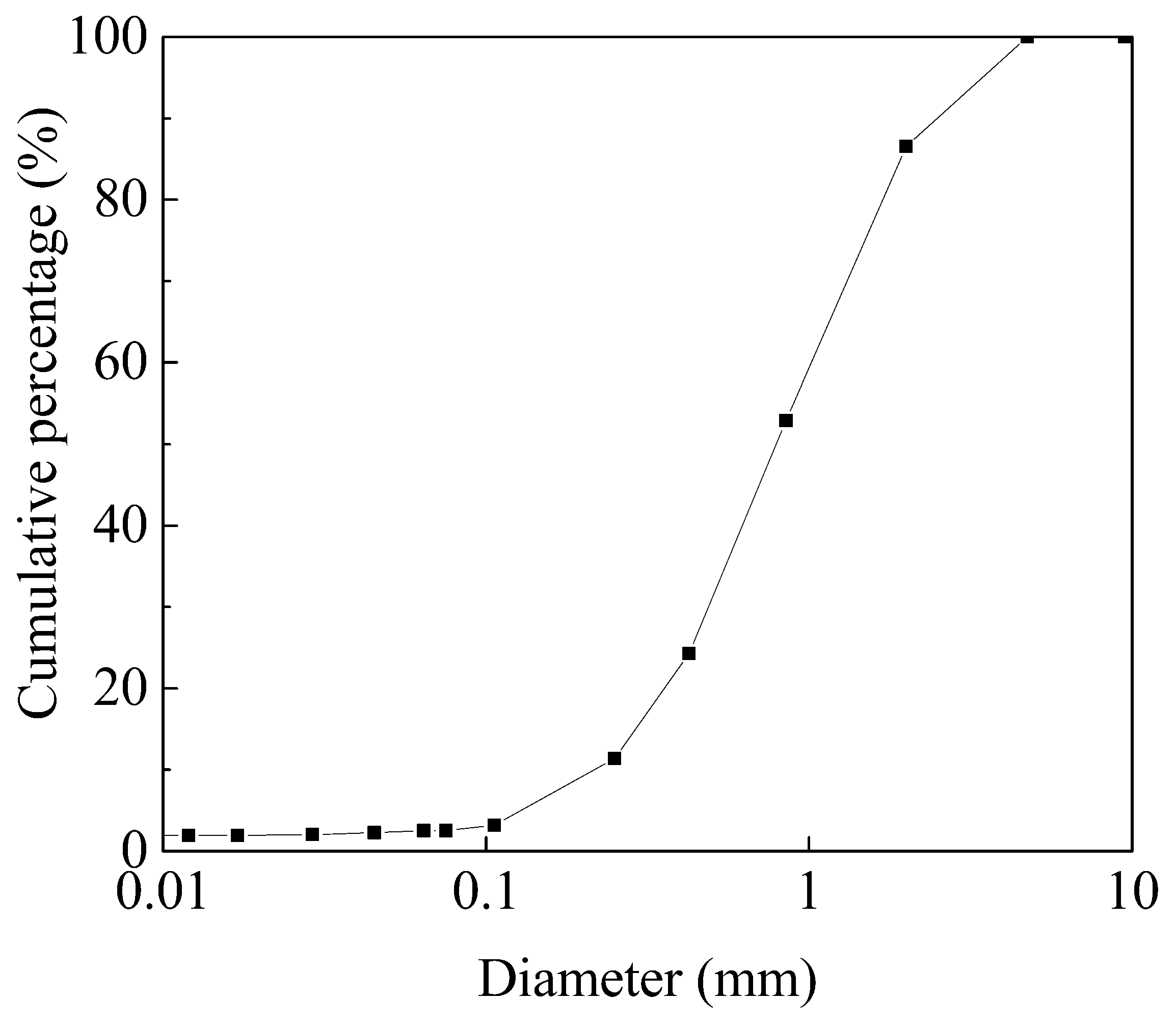
2.1.1. Low-Permeability Soil
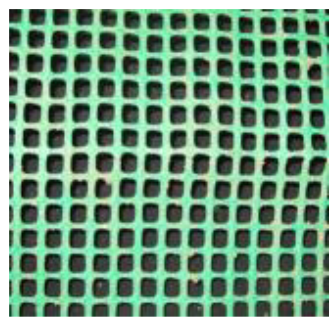
2.1.2. Geogrid
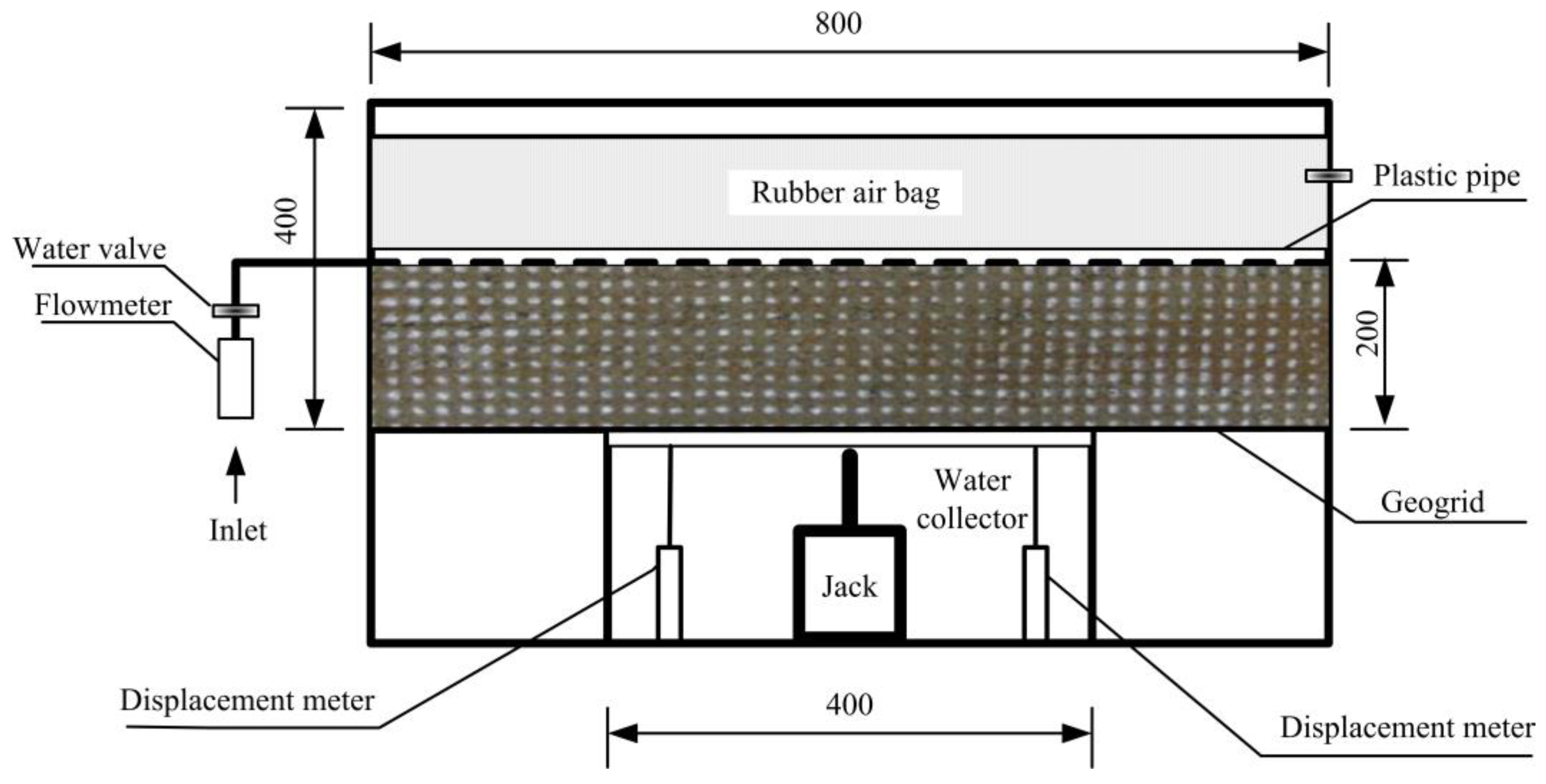
2.2. Apparatus
2.3. Test Procedure
2.3.1. Experimental Scheme
2.3.2. Methods
3. Results and Discussion
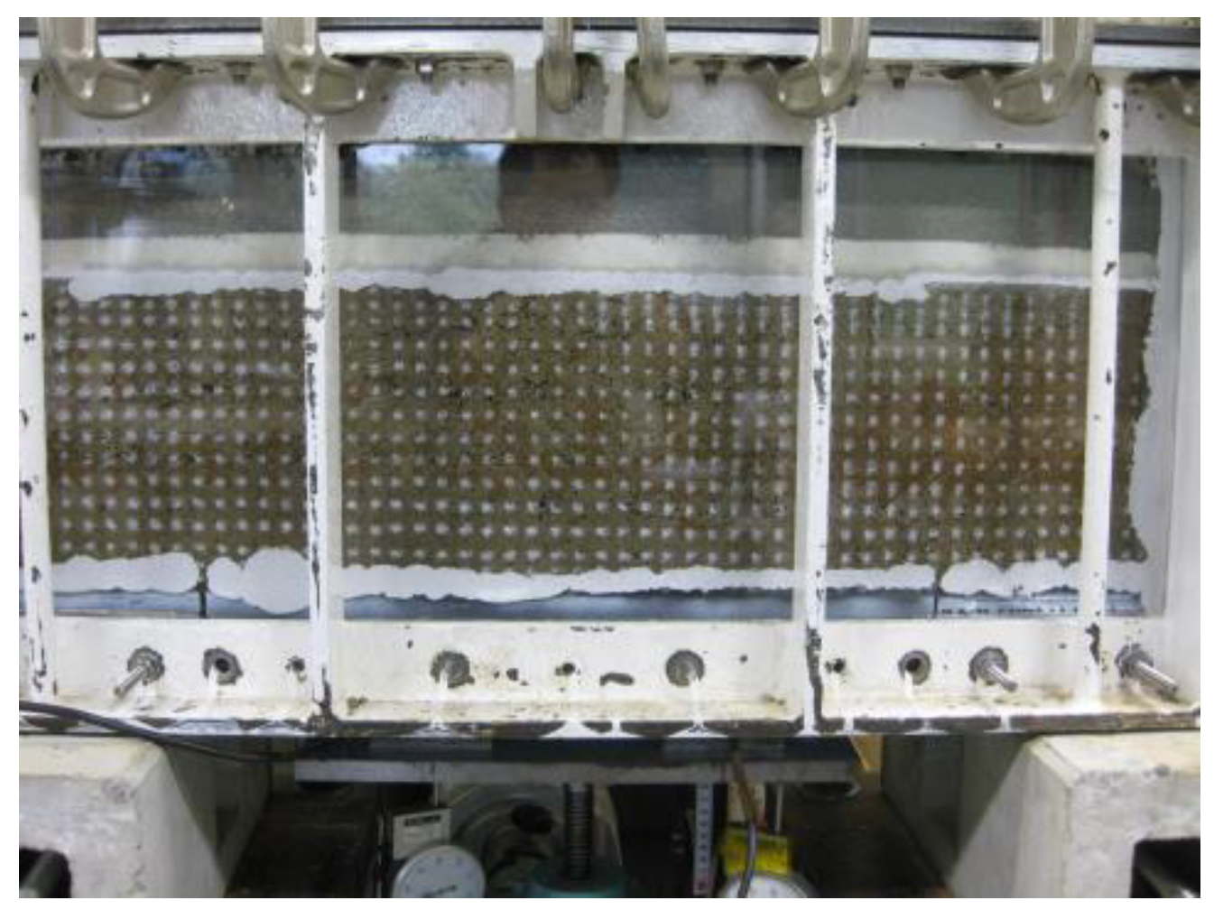
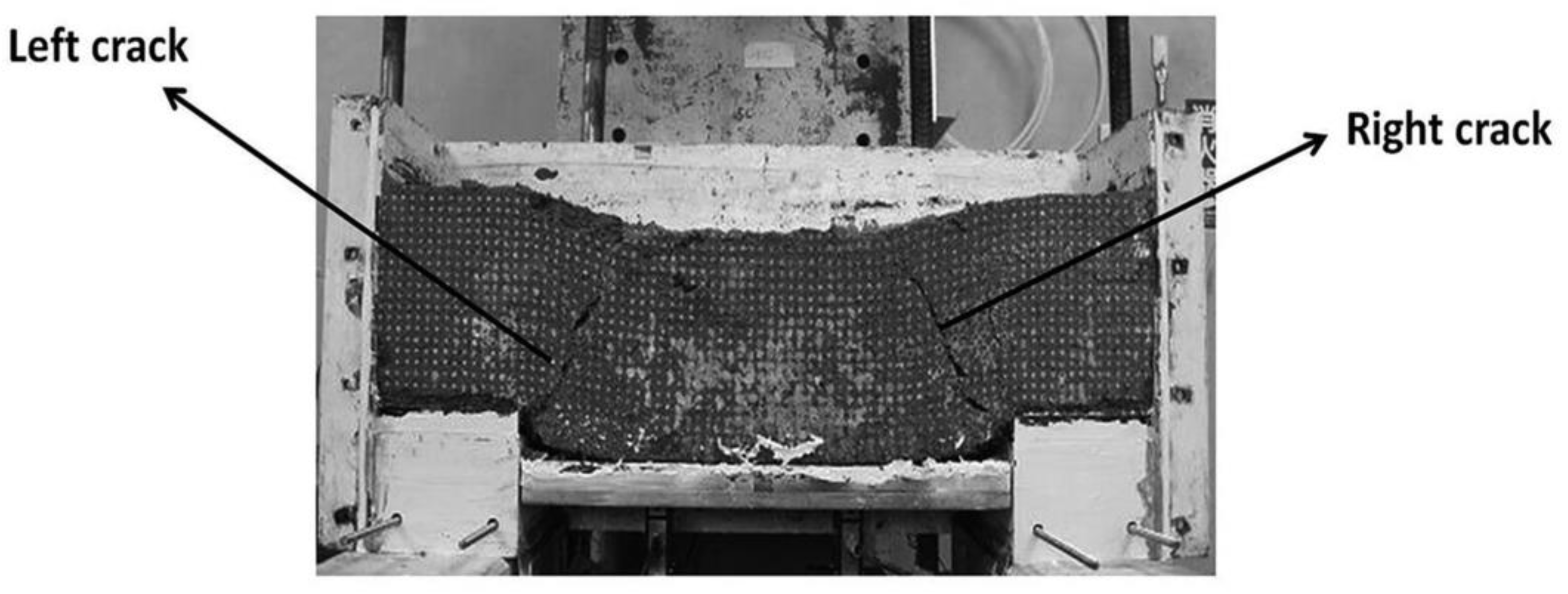
3.1. Settlement and Crack Development
3.2. Crack Angle and Size
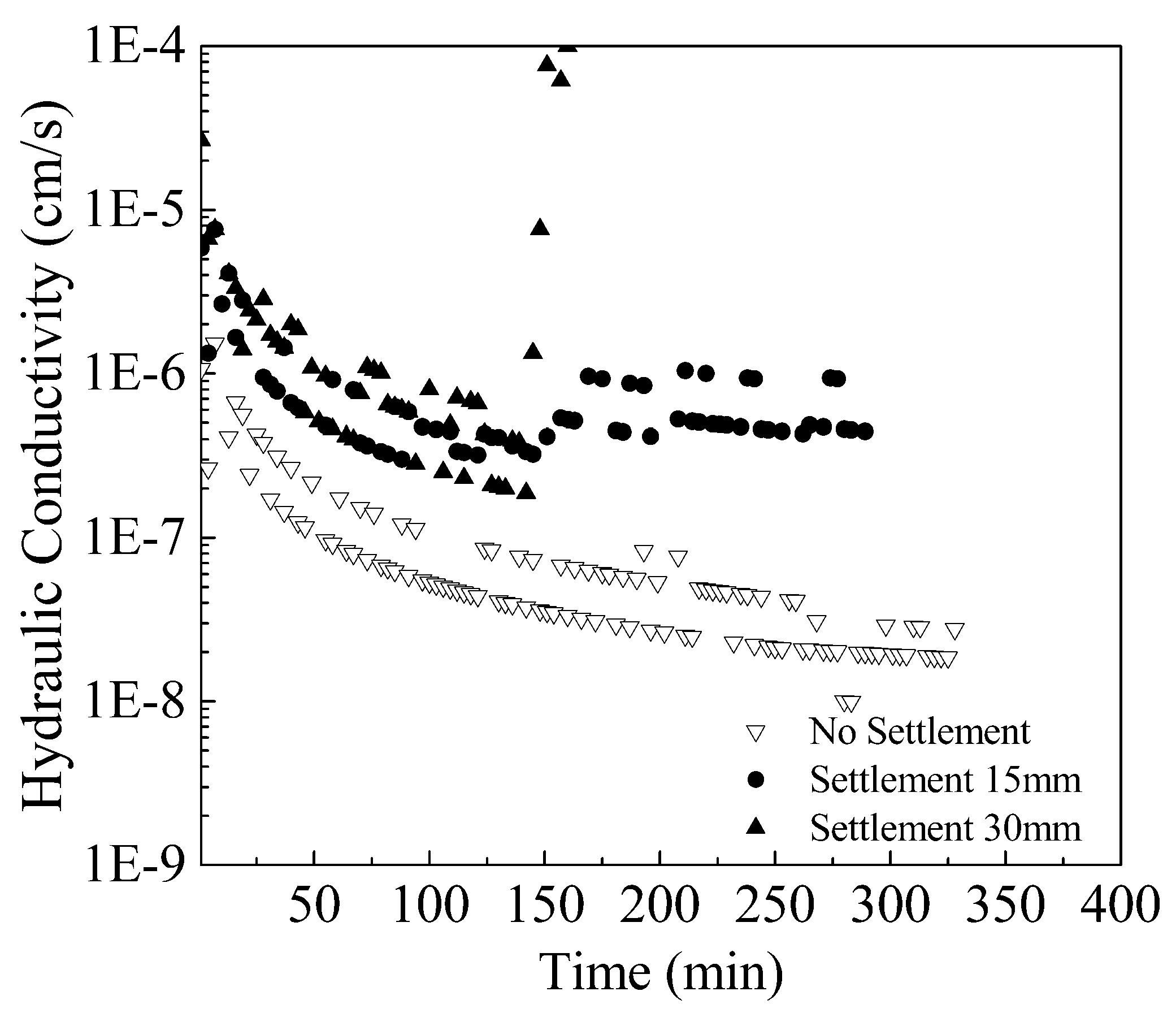
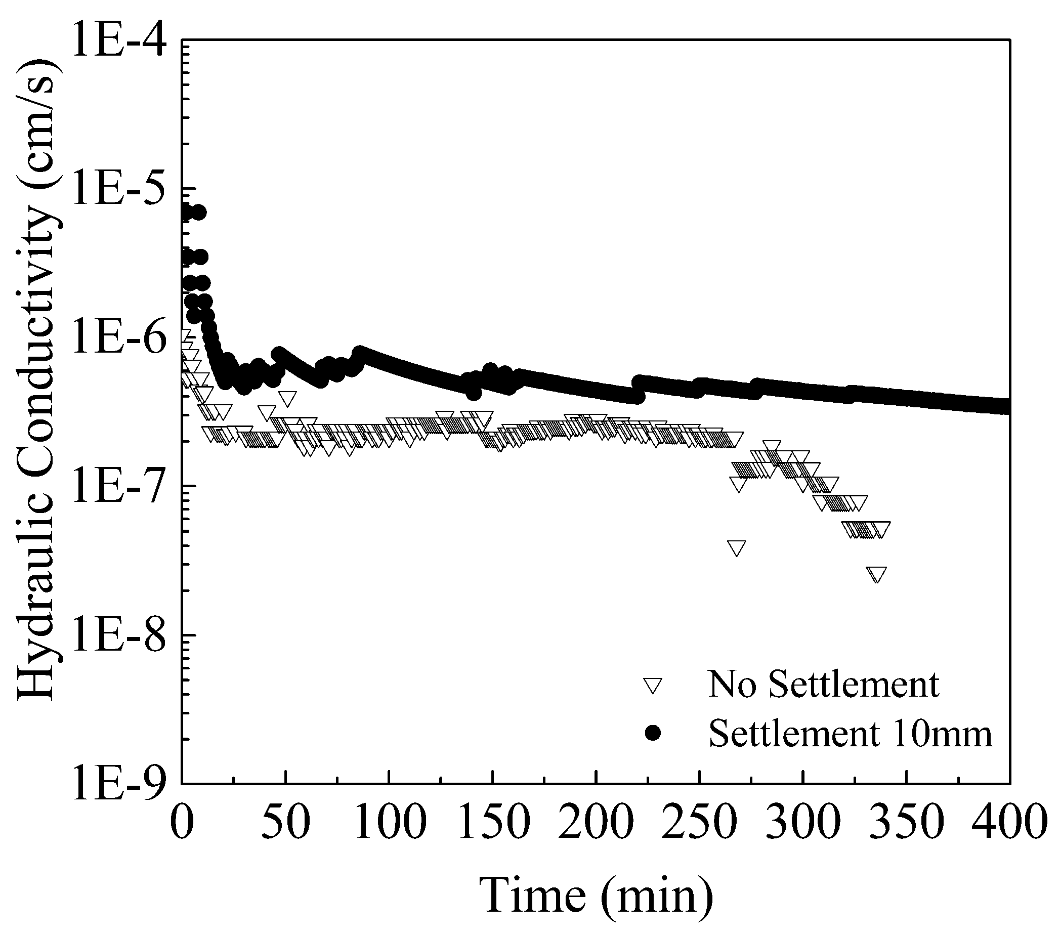
3.3. Settlement and Hydraulic Conductivity
Settlement and Hydraulic Conductivity
4. Conclusions
- (1)
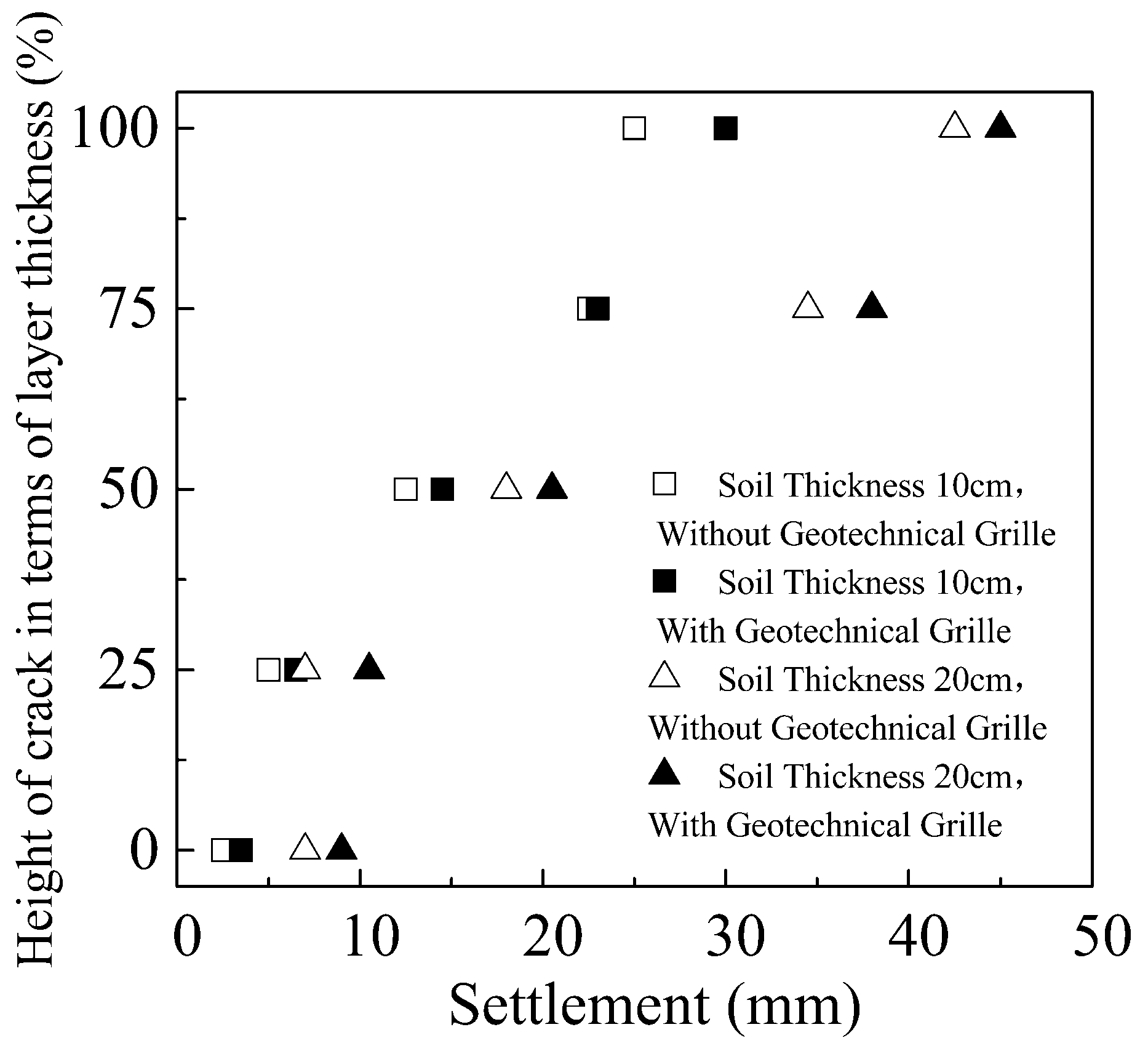
- Bentonite-sand mixtures reinforced with geogrid restrained carcking better. Un-reinforced bentonite-sand mixtures of 100 mm and 200 mm thickness were observed to begin cracking at settlement levels of 2.5 mm and 7 mm, respectively. The bentonite-sand mixtures of 100 mm and 200 mm thickness with geogrid reinforcement were observed to begin cracking at settlement levels of 3.5 mm and 9 mm, respectively. When settlement reached 25 and 42.5 mm, cracks for 100 mm and 200 mm thick bentonite-sand mixtures without geogrid being penetrated completely. Moreover, cracks for 100 mm and 200 mm thick bentonite-sand mixtures without geogrid penetrated completely when settlement reached 30 and 45 mm.
- (2)
- Bentonite-sand mixtures reinforced with geogrid restrained carck width better. The maximum crack width for 100 mm and 200 mm thick bentonite-sand mixtures unreinforced with geogrid was found be 15 mm and 20 mm. The cracks of bentonite-sand mixtures reinforced with geogrid were <1 mm in width when the crack approached 50% of the layer thickness. When settlement reached maximum settlement, crack width kept around 3mm no matter whether the crack thickness was 100 mm or 200 mm.
- (3)
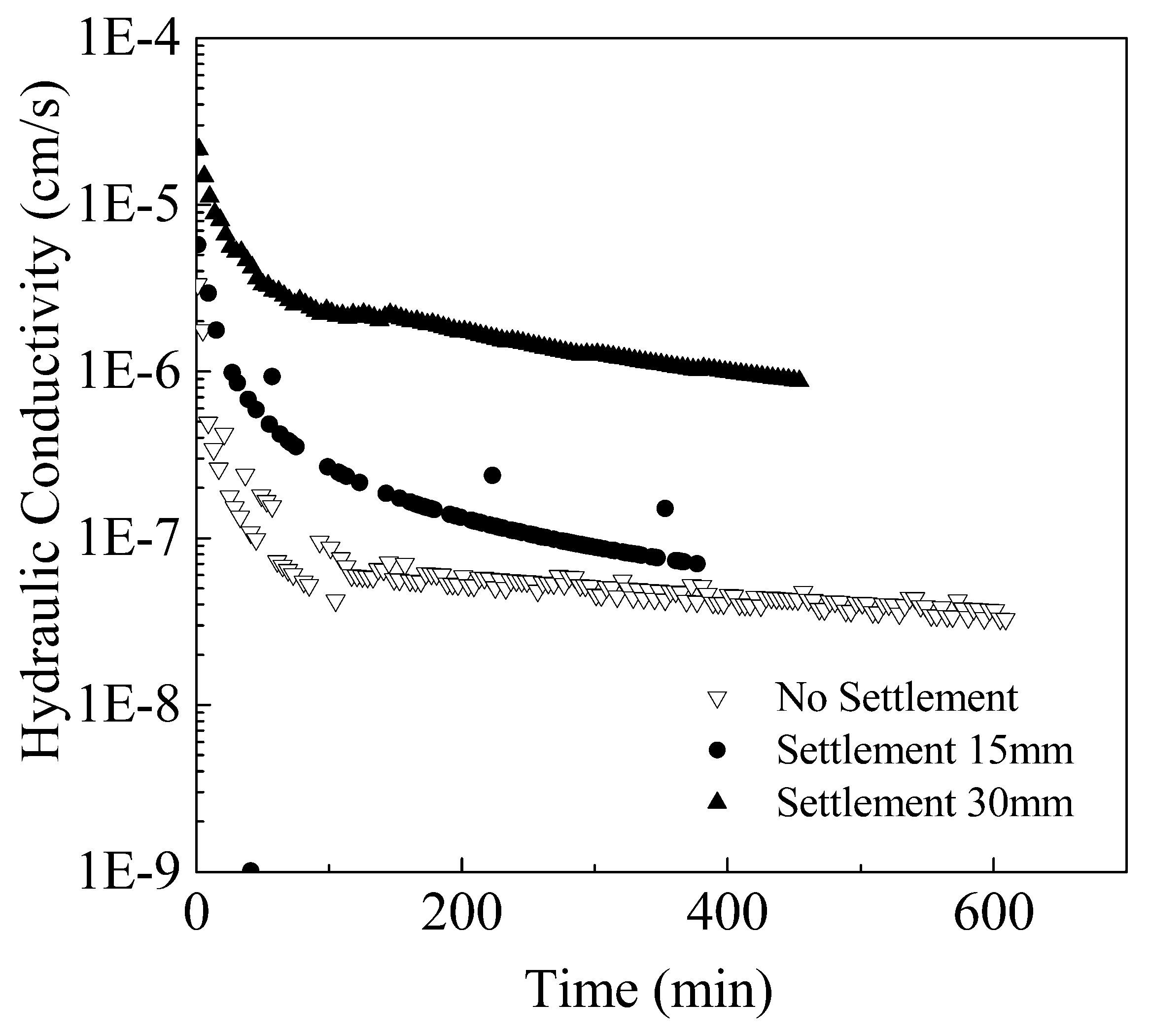
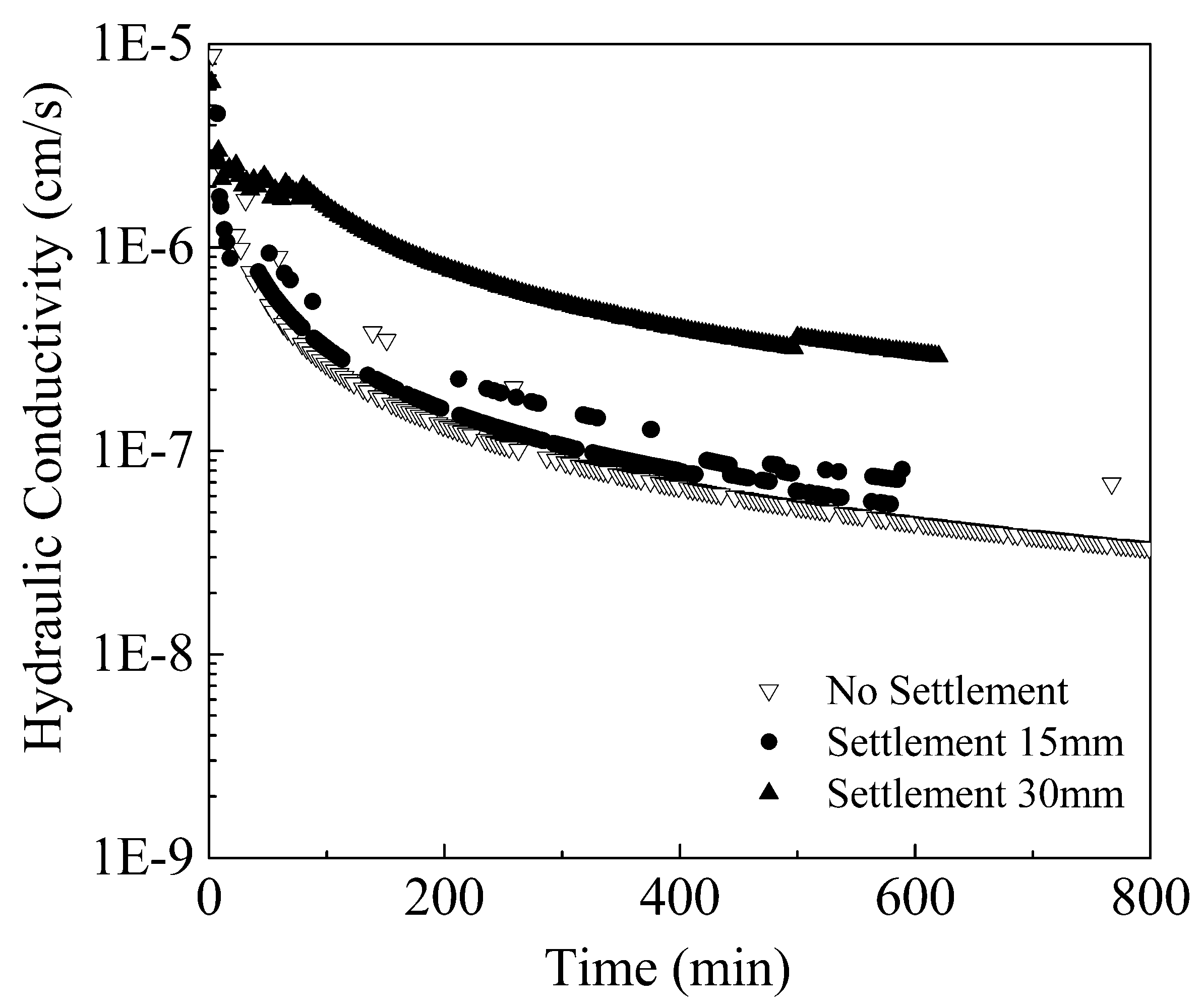
- The settlement levels for bentonite-sand mixtures of 100 mm thickness with and without geogrid reinforcement was found to be 10 mm and 15 mm, respectively, when its hydraulic conductivity was around 5 × 10⁻⁷ cm/s. With the crack approaching 70% of the layer thickness, the hydraulic conductivity of bentonite-sand mixtures with and without geogrid reinforcement increased to 2 × 10⁻⁷ cm/s and 7 × 10⁻⁷ cm/s, respectively.
- (4)
- The effect of geogrid on development of crack angle of bentonite-sand mixtures is little. Angle of the cracks just initiated was relatively small, at around 40–45°. The angle increased gradually as the crack continued to grow, with angle of the penetrating crack at about 60°.
Author Contributions
Funding
Conflicts of Interest
References
- China Architecture & Building. 2012 Technical Code for Geotechnical Engineering of Municipal Solid Waste Sanitary Landfill; CJJ 176–2012; China Architecture & Building Press: Beijing, China, 2012. [Google Scholar]
- Albrecht, B.; Benson, C. Effect of desiccation on compacted natural clays. J. Geotech. Geoenviron. Eng. 2001, 127, 67–75. [Google Scholar] [CrossRef]
- Krisnanto, S.; Rahardjo, H.; Fredlund, D.G.; Leong, E.C. Water content of soil matrix during lateral water flow through cracked soil. Eng. Geol. 2016, 210, 168–179. [Google Scholar] [CrossRef]
- Ling, D.; Xu, Z.; Cai, W.; Wang, Y. Experimental study on characteristics of bending cracks of compacted soil beams. Chin. J. Geotech. Eng. 2015, 37, 1165–1172. [Google Scholar] [CrossRef]
- Cai, W.; Ling, D.; Xu, Z.; Chen, Y. Influence of preferential flow induced by a single crack on anti-seepage performance of clay barrier. Rock Soil Mech. 2014, 7598, 2838–2845. [Google Scholar]
- Vo, T.D.; Pouya, A.; Hemmati, S.; Tang, A.M. Numerical modelling of desiccation cracking of clayey soil using a cohesive fracture method. Comput. Geotech. 2017, 85, 15–27. [Google Scholar] [CrossRef]
- Zhang, B.; Li, Q.; Yuan, H.; Sun, X. Tensile Fracture Characteristics of Compacted Soils under Uniaxial Tension. J. Mater. Civ. Eng. 2015, 27. [Google Scholar] [CrossRef]
- Chen, X.; Zhang, J.; Li, Z. Shear behaviour of a geogrid-reinforced coarse-grained soil based on large-scale triaxial tests. Geotext. Geomembr. 2014, 4, 312–328. [Google Scholar] [CrossRef]
- Zhang, Y.; Wang, H.M.; Yan, L.F. Test research on tensile properties of compacted clay. Rock Soil Mech. 2013, 34, 2151–2157. [Google Scholar]
- Zhang, Y.; Zhang, B.Y.; Li, G.X.; Sun, X. Combined tension-compression triaxial tests and extended Duncan-Chang model of compacted clay. Chin. J. Geotech. Eng. 2010, 32, 999–1004. [Google Scholar] [CrossRef]
- Dickinson, S.; Brachman, R.W.I. Deformations of a geosynthetic clay liner beneath a geomembrane wrinkle and coarse gravel. Geotext. Geomembr. 2006, 24, 285–298. [Google Scholar] [CrossRef]
- Sharma, H.D.; De, A. Municipal Solid Waste Landfill Settlement: Postclosure Perspectives. J. Geotech. Geoenviron. Eng. 2007, 133. [Google Scholar] [CrossRef]
- Gourc, J.P.; Camp, S.; Viswanadham, B.V.S.; Rajesh, S. Deformation behavior of clay cap barriers of hazardous waste containment systems: Full-scale and centrifuge tests. Geotext. Geomembr. 2010, 28, 281–291. [Google Scholar] [CrossRef]
- Viswanadham, B.V.S.; Rajesh, S. Centrifuge model tests on clay based engineered barriers subjected to differential settlements. Appl. Clay Sci. 2009, 42, 460–472. [Google Scholar] [CrossRef]
- Camp, S.; Gourc, J.P.; Ple, O. Landfill clay barrier subjected to cracking: Multi-scale analysis of bending tests. Appl. Clay Sci. 2010, 48, 384–392. [Google Scholar] [CrossRef]
- Viswanadham, B.V.; Jha, B.K.; Sengupta, S.S. Centrifuge Testing of Fiber-Reinforced Soil Liners for Waste Containment Systems. Pract. Period. Hazard. Toxic Radioact. Waste Manag. 2009, 13, 45–58. [Google Scholar] [CrossRef]
- Plé, O.; Manicacci, A.; Gourc, J.P.; Camp, S. Flexural behaviour of a clay layer: Experimental and numerical study. Can. Geotech. J. 2012, 49, 485–493. [Google Scholar] [CrossRef]
- Viswanadham, B.V.S.; Jessberger, H.L. Centrifuge Modeling of Geosynthetic Reinforced Clay Liners of Landfills. J. Geotech. Geoenviron. Eng. 2005, 131, 564–574. [Google Scholar] [CrossRef]
- Viswanadham, B.V.S.; Muthukumaran, A.E. Influence of geogrid layer on theintegrity of compacted clay liners of landfills. Soils Found 2007, 47, 519–534. [Google Scholar] [CrossRef]
- Melchior, S.; Sokollek, V.; Berger, K.; Vielhaber, B.; Steinert, B. Results from 18 Years of In Situ Performance Testing of Landfill Cover Systems in Germany. J. Environ. Eng. 2010, 136, 815–823. [Google Scholar] [CrossRef]
- Hettiarachchi, H.; Meegoda, J.; Hettiaratchi, P. Effects of gas and moisture on modeling of bioreactor landfill settlement. Waste Manag. 2009, 29, 1018–1025. [Google Scholar] [CrossRef] [PubMed]
- Hirobe, S.; Oguni, K. Coupling analysis of pattern formation in desiccation cracks. Comput. Methods Appl. Mech. Eng. 2016, 307, 470–488. [Google Scholar] [CrossRef]
- Zhu, H.; He, X.; Wang, K.; Su, Y.; Wu, J. Interactions of vegetation succession, soil bio-chemical properties and microbial communities in a Karst ecosystem. Eur. J. Soil Biol. 2012, 51, 1–7. [Google Scholar] [CrossRef]
- Albright, W.H.; Benson, C.H.; Gee, G.W.; Abichou, T.; Tyler, S.W.; Rock, S. Field performance of a compacted clay langfill final cover at a humid site. J. Geotech. Geoenviron. Eng. 2006, 132, 1393–1403. [Google Scholar] [CrossRef]
- He, J.; Wang, Y.; Li, Y.; Ruan, X. Effects of leachate infiltration and desiccation cracks on hydraulic conductivity of compacted clay. Water Sci. Eng. 2015, 8, 151–157. [Google Scholar] [CrossRef]
- Kodikara, J.; Costa, S. Desiccation Cracking in Clayey Soils: Mechanisms and Modelling; Multiphysical Testing of Soils and Shales; Laloui, L., Ferrari, A., Eds.; Springer: Berlin/Heidelberg, Germany, 2013; pp. 21–32. [Google Scholar]
- Gui, Y.L.; Zhao, Z.Y.; Kodikara, J.; Bui, H.H.; Yang, S.Q. Numerical modelling of laboratory soil desiccation cracking using UDEC with a mix-mode cohesive fracture model. Eng. Geol. 2016, 202, 14–23. [Google Scholar] [CrossRef]
- Sima, J.; Jiang, M.; Zhou, C. Numerical simulation of desiccation cracking in a thin clay layer using 3D discrete element modeling. Comput. Geotech. 2014, 56, 168–180. [Google Scholar] [CrossRef]
- Wang, D.Y.; Tang, C.S.; Cui, Y.J.; Shi, B.; Li, J. Effects of wetting-drying cycles on soil strength profile of a silty clay in micro-penetrometer tests. Eng. Geol. 2016, 206, 60–70. [Google Scholar] [CrossRef]
- Tang, C.S.; Wang, D.Y.; Shi, B.; Li, J. Effect of wetting-drying cycles on profile mechanical behavior of soils with different initial conditions. Catena 2016, 139, 105–116. [Google Scholar] [CrossRef]


| S.No. | Study Focus | d (mm) | Geogrid |
|---|---|---|---|
| 1 | Deformation and cracks | 100 | No |
| 2 | Deformation and cracks | 200 | No |
| 3 | Deformation and cracks | 100 | Yes |
| 4 | Deformation and cracks | 200 | Yes |
| 5 | Hydraulic conductivity | 100 | No |
| 6 | Hydraulic conductivity | 200 | No |
| 7 | Hydraulic conductivity | 100 | Yes |
| 8 | Hydraulic conductivity | 200 | Yes |
| Crack Development | Angle (°) | |||
|---|---|---|---|---|
| Soil Thickness 100 mm | Soil Thickness 200 mm | |||
| No | Yes | No | Yes | |
| Initiation | 40 | 45 | 45 | 40 |
| 25% of thickness | 47 | 45 | 50 | 48 |
| 50% of thickness | 50 | 50 | 55 | 53 |
| 75% of thickness | 53 | 57 | 60 | 59 |
| Penetration | 62 | 59 | 58 | 60 |
© 2018 by the authors. Licensee MDPI, Basel, Switzerland. This article is an open access article distributed under the terms and conditions of the Creative Commons Attribution (CC BY) license (http://creativecommons.org/licenses/by/4.0/).
Share and Cite
Xu, S.; Li, C.; Liu, J.; Bian, M.; Wei, W.; Zhang, H.; Wang, Z. Deformation and Hydraulic Conductivity of Compacted Clay under Waste Differential Settlement. Processes 2018, 6, 123. https://doi.org/10.3390/pr6080123
Xu S, Li C, Liu J, Bian M, Wei W, Zhang H, Wang Z. Deformation and Hydraulic Conductivity of Compacted Clay under Waste Differential Settlement. Processes. 2018; 6(8):123. https://doi.org/10.3390/pr6080123
Chicago/Turabian StyleXu, Sifa, Cuifeng Li, Jizhuang Liu, Mengdan Bian, Weiwei Wei, Hao Zhang, and Zhe Wang. 2018. "Deformation and Hydraulic Conductivity of Compacted Clay under Waste Differential Settlement" Processes 6, no. 8: 123. https://doi.org/10.3390/pr6080123
APA StyleXu, S., Li, C., Liu, J., Bian, M., Wei, W., Zhang, H., & Wang, Z. (2018). Deformation and Hydraulic Conductivity of Compacted Clay under Waste Differential Settlement. Processes, 6(8), 123. https://doi.org/10.3390/pr6080123