Review

Energy Considerations for Plasma-Assisted N-Fixation Reactions

1
Laboratory of Chemical Reactor Engineering/Micro Flow Chemistry and Process Technology, Department of Chemical Engineering and Chemistry, Eindhoven University of Technology, P.O. Box 513, 5600 MB Eindhoven, The Netherlands
2
Innovation Management, Verfahrenstechnik & Engineering, Evonik Industries AG, Rodenbacher Chaussee 4, 63457 Hanau-Wolfgang, Germany
*
Author to whom correspondence should be addressed.
Processes 2014, 2(4), 694-710; https://doi.org/10.3390/pr2040694
Submission received: 26 February 2014 / Revised: 27 June 2014 / Accepted: 22 July 2014 / Published: 26 September 2014

Abstract

:
In a time of increasing concerns about the immense energy consumption and poor environmental performance of contemporary processes in the chemical industry, there is great need to develop novel sustainable technologies that enhance energy efficiency. There is abundant chemical literature on process innovations (laboratory-scale) around the plasma reactor itself, which, naturally, is the essential part to be intensified to achieve a satisfactory process. In essence, a plasma process needs attention beyond reaction engineering towards the process integration side and also with strong electrical engineering focus. In this mini-review, we have detailed our future focus on the process and energy intensification of plasma-based N-fixation. Three focal points are mainly stressed throughout the review: (I) the integration of renewable energy; (II) the power supply system of plasma reactors and (III) process design of industrial plasma-assisted nitrogen fixation. These different enabling strategies will be set in a holistic and synergetic picture so as to improve process performance.

1. Introduction

Nitrogen fixation is indisputably one of the most important chemical processes for both biological and industrial applications. It is a reaction of vital importance as it converts atmospheric nitrogen into ammonia or other useful nitrogen compounds that can be directly absorbed by living organisms as nutrients. It also plays an integral part in the nitrogen cycle and, thereby, in the conservation of all ecosystems. However, apart from its natural importance, fixed nitrogen, and more precisely ammonia, is a fundamental component of fertilizers and other chemicals, and is primarily manufactured via the Haber-Bosch process. It is the second largest commodity in the global chemicals industry and almost 80% of its production is utilized in the manufacture of fertilizer [1]. It is worth mentioning that, in 2011, the world ammonia market exceeded 120 million tons, whereas it is expected to reach up to 160 million tons by the end of 2020 [2].
From an energy point of view, industrial ammonia synthesis is the most energy intensive chemical process, consuming approximately 36.6 GJ/ton NH3 for natural gas feedstock and achieving an energy efficiency of about 60% [3,4,5,6]. For heavier hydrocarbon feedstock, the specific energy consumption can increase considerably, reaching a value up to 169 GJ/t NH3 for coal gasification. In addition to that, the environmental performance of current state-of–the-art industrial nitrogen fixation processes is relatively poor, being characterized by high carbon dioxide (CO2) and nitrous oxide (N2O) emissions. In particular, a typical natural gas-based ammonia plant utilizing steam reforming process, generates emissions of 1.15–1.30 kg·CO2/kg NH3, while for partial oxidation, they reach up to 2–2.6 kg·CO2/kg NH3 [7]. Additionally, nitric acid plants employing non-selective catalytic reduction technology and operating under medium pressure, emit an average amount of 7 kg N2O/ton HNO3, whereas for low and high pressure conditions, emissions reach an average value of 5 and 9 kg N2O/ton HNO3, respectively [8].
Considering the increasing demand of fertilizers, the high energy intensity and environmental concerns triggered by industrial nitrogen fixation, the need to develop and integrate more sustainable processes becomes imperative. A preliminary contribution in that direction has been made by plasma technology which is perceived to be a promising novel approach for improving process environmental and energy efficiency. In terms of nitrogen fixation, there is literature documented on its synthesis in different plasma reactors under varied operating conditions. Ammonia synthesis has been realized in a dielectric barrier discharge reactor under N2/H2 feed flow rate of 0.73 L/min, operating temperature of 80 °C and 1 bar pressure [9]. The maximum production efficiency of 1.83 g/kWh has been achieved for an applied power of 57.2 W and NH3 concentration of 1400 ppm [9]. Furthermore, the synthesis of nitric oxide has also been studied in a microwave discharge plasma reactor for a nitrogen feed with 35% O2 content at a flow rate of 22 Nl/h, an operating pressure of 50 torr and an applied power of 10 W [10]. Under these conditions and the incorporation of MoO3 catalyst, an energy consumption of 28 MJ/kg NO has been reported, which equals to 35% energy improvement compared to experimental results without the use of catalyst [10].
The research mentioned above serves as illustrative example of the synthesis of ammonia and nitric oxide via non-thermal plasma technology. Non-thermal plasma reactors are linked to relatively high reaction selectivity and energy efficiency due to the fact that the supplied electrical power is channeled predominately to excite electrons rather than heat the bulk volume of the plasma gas [11,12]. In addition to this, non-thermal plasmas generated at atmospheric pressure and temperature demonstrate clear advantages of low operational costs [13]. However, when it comes to industrial application it becomes necessary to adopt a holistic design approach and consider a scale-up process and its optimization with respect to the energy efficiency, environmental and economic performance. This particular point is initiated in the context of the “Microwave, Ultrasonic and Plasma assisted Syntheses” (MAPSYN) Project which focuses on the sustainable process intensification of nitrogen-fixation reactions and selective hydrogenations reinforced by plasma and microwaves/ultrasound technology respectively [14,15]. In principle, the project aims to overcome the energy and environmental challenges related to the massive production of industrially-fixed nitrogen by developing flexible “small-scale processes”, which will incorporate the advantages of the aforementioned alternative energy sources in novel plasma reactors. A typical example illustrating the applicability of this concept is the technology of a vehicle on-board ammonia production from water and nitrogen carried out in a Dielectric Barrier Discharge (DBD) plasma reactor at a variety of operating conditions [16].

2. Methodology-Approach

As it can be deduced from the previous discussion, the initial conceptualization of industrial plasma-assisted nitrogen fixation requires certain design considerations that will lead to an energy efficient and sustainable chemical process. In order to realize this, the process design model of ammonia and nitric acid synthesis—incorporating the nitric oxide generation as a reaction intermediate—will be developed for both conventional and plasma-assisted production pathways. Simulating the selected plasma-assisted processes in the Aspen Plus software tool (Aspen Technology, Inc.: Burlington, MA, USA) is likely to facilitate the energy efficiency benchmarking and optimization procedure with the corresponding conventional industrial operations.
The simulation model of the scaled-up plasma ammonia and nitric acid will primarily satisfy the prerequisites of a typical medium-scale ammonia and nitric acid plant with respect to the feedstock properties and flow rate, as well as, the type of upstream and downstream activities. However, at a later stage when the simulation optimization for the given plasma-assisted processes has been achieved, certain design modifications will be incorporated related to the capacity/capability of upstream and downstream activities based on different supply chains scenarios, the hydrogen production source, as well as, the power supply system of plasma reactors. These considerations, as shown in Figure 1, will be briefly discussed below with the view to providing a general overview of the upcoming energy challenges associated with the design and integration of plasma technology to conventional-established chemical processes.
Figure 1. Focus areas of energy considerations for plasma-assisted nitrogen fixation.
Processes 02 00694 g001

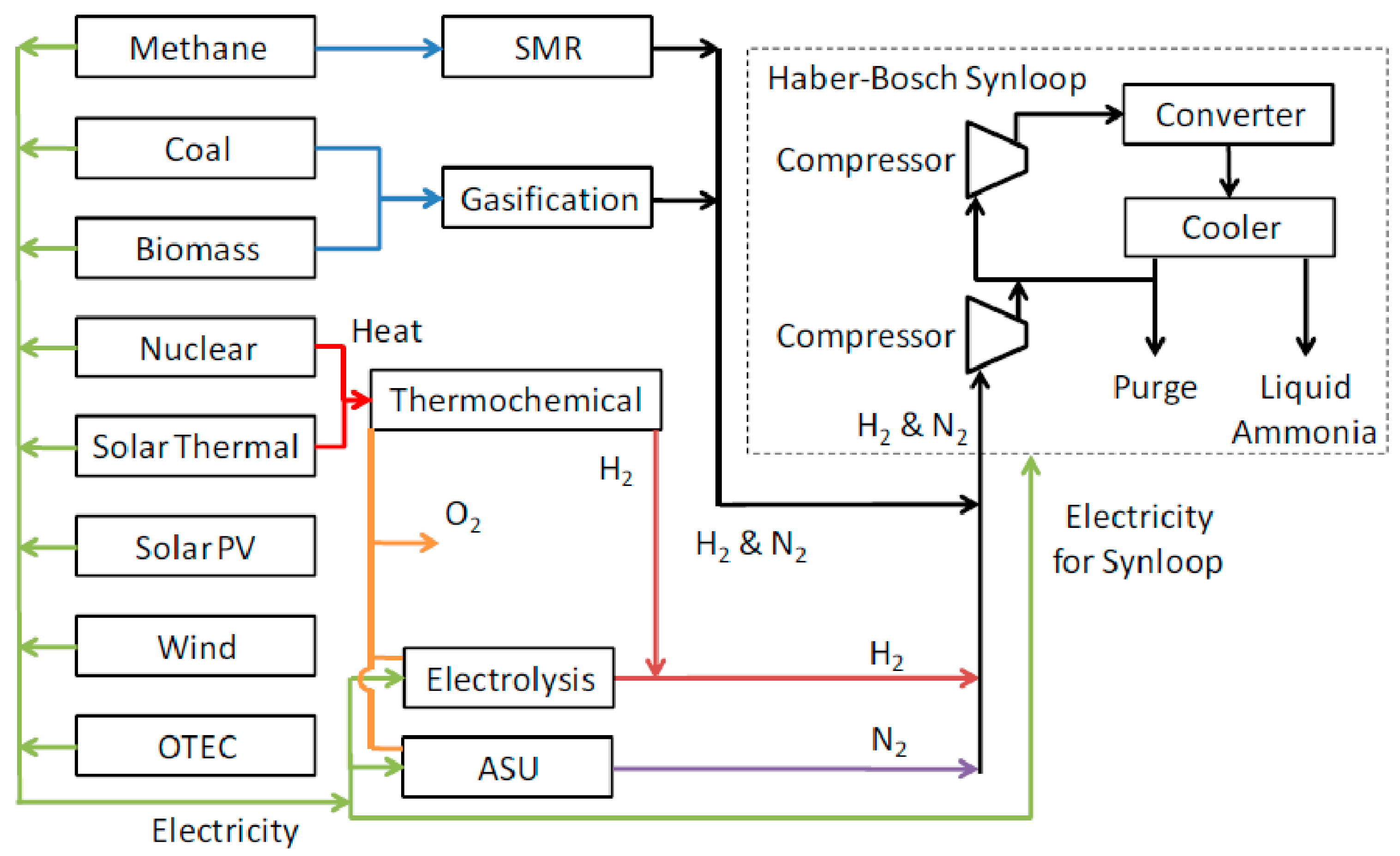
2.1. Integration of Renewable Energy Sources

Almost 97% of the energy requirements of a typical ammonia plant is associated with hydrogen generation via natural gas steam reforming [3]. This fact indicates the necessity to consider renewable energy sources as an alternative electricity power supply system and hydrogen production source. In essence, numerous researchers have conducted detailed studies on the electricity generation via solar and wind energy, as well as hydropower energy [13,17,18,19,20]. Case studies on ammonia production via alternative energy sources will be presented below.
Ammonia synthesis via alternative energy sources has been conceptualized for both electricity and hydrogen production based on different technologies as shown in Figure 2 [13]. Although methane steam reforming is a more economically and energy efficient production technique of hydrogen, compared to hydrolysis or air separation, the latter can be proved feasible, if combined with renewable sources what have higher or comparable electricity generation efficiency as the conventional one. For example, the efficiency of electricity generation by hydro, wind and solar can reach up to 95%, 35% and 23%, respectively, whereas natural gas turbine and steam turbine coal-fired power plants have efficiencies of 39% and 47%, correspondingly [21]. These facts, in combination with the following case studies, provide some promising industrial perspectives of the renewable energy sources that will be thoroughly investigated in the content of the MAPSYN project.
Figure 2. Ammonia synthesis based on different hydrogen sources. Reprinted with permission from [13]. Copyright 2008, Iowa State University.
Processes 02 00694 g002
Avery et al. extended the existing knowledge on Ocean Thermal Energy Conversion (OTEC) technology by proposing the design of a 325 MWe plant-ship generating 1000 tons of ammonia per day [22,23]. The plant would basically exploit the temperature gradient between the surface and deep ocean water to generate electric power onboard which would be used, in turn, for ammonia synthesis and other energy-demanding operations. As it can be clearly deduced from the Figure 3, the majority of the OTEC power is allocated to hydrogen and nitrogen production via water electrolysis and air liquefaction, respectively, whereas the rest covers propulsion and other related needs.
Figure 3. Ammonia plantship powered by OTEC. Reprinted with permission from [23]. Copyright 1985, International Association for Hydrogen Energy.
Processes 02 00694 g003
An effort towards commercialization has been made by the University of Minnesota (West Central Research and Outreach Center), which inaugurated the operation of the first wind-powered ammonia pilot plant in 2013 (Figure 4). Early-bird results from plant performance testing demonstrated an energy consumption of 60 GJ/ton NH3 [24]. Although, the value is relatively higher than the conventional ammonia production by steam reforming, the environmental impact of the process is considerably lower as less fossil fuels are utilized for electricity generation. It is also worth mentioning that the plant undergoes optimization and new plants are likely to achieve an energy consumption of 8 MWh/ton NH3 where average consumption for conventional synthesis route is 12 MWh/ton NH3 [25].
Figure 4. Ammonia pilot plant powered by wind in Minnesota. Reprinted with permission from [17]. Copyright 2013, University of Minnesota.
Processes 02 00694 g004
As can be deduced from the above case studies, the integration of alternative energy in plasma-assisted nitrogen fixation can be feasible and sustainable, provided the optimum plant design with respect to the location of the resources has been selected. This is likely to facilitate and maximize the resource utilization and, also, reduce the overall energy costs and the environmental footprint of the given processes. In essence, in the framework of the MAPSYN project, different scenarios for certain alternative energy sources will be developed and optimized based on discrete criteria, such as location, capacity, desired design, operational flexibility, etc. A detailed report on this topic will be provided at a later stage, when research has demonstrated progress enough to generate concrete results.

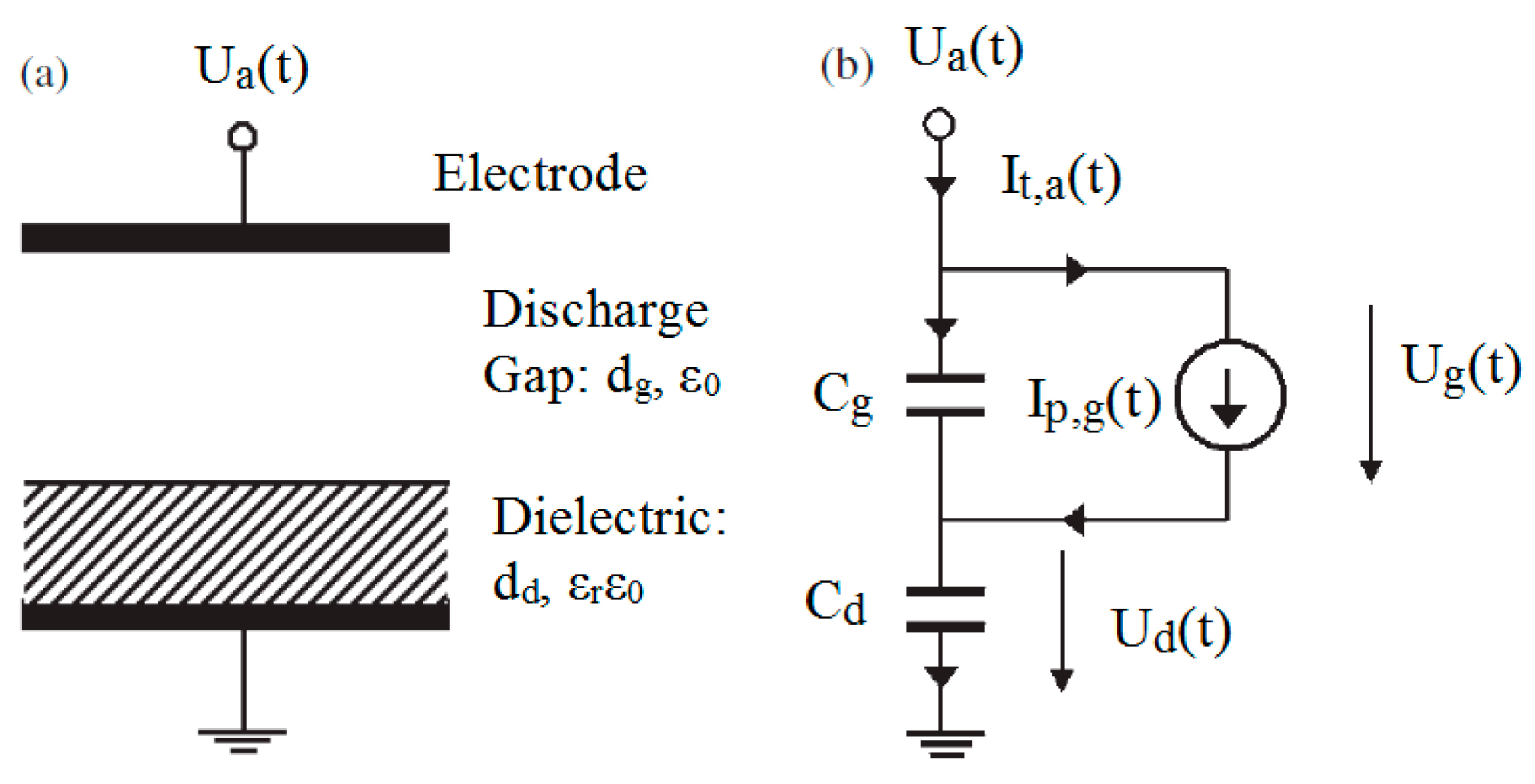
2.2. Power Supply System of Plasma Reactors

Regarding the energy consumption of plasma-assisted nitrogen fixation, all the reported literature focuses mainly on the performance of the plasma reactors rather than the efficiency of the applied power supply system. In the case of plasma processing, the term efficiency implies the real amount of power transferred in the discharge plasma, as compared to what is generated. This has become a focus area of many researchers who have stressed the importance of the power supply system in the overall energy consumption of plasma reactors [26,27,28,29,30,31]. Especially for DBD plasma reactors that will be also utilized in the MAPSYN project, there is reported literature on the principle of impedance matching as a way to enhance the overall electrical performance of both the plasma reactor and power generator systems. To exemplify, two case studies will be provided below, illustrating the practical application of the aforementioned principle in reducing DBD impedance.
Prior to the citation of two illustrative examples that focus on the impedance matching in DBD reactors, it would be wise to explain the principle of impedance matching. As seen in Figure 5, in a simple electrical circuit, the power generator (EG) is meant to provide power to a load resistance (RL) [32]. However, due to the internal resistance of the source (RG), a considerable amount of the generated power is wasted as heat whenever the circuit is closed. This actually implies that less power will be always transferred to the load compared to the generated one. In order to minimize this effect and maximize the power transfer to the load, the optimal position, as depicted in the Figure 6, should be achieved where the internal impedance is equal to the load impedance. In that case, the maximum power transfer is achieved with a power transfer efficiency of 50%, which implies that half of the generated power is dissipated by the RL, whereas the other half is allocated to heat losses induced by the RG [32]. The process of reducing load impedance and making it equal to the internal impedance is called impedance matching and is accomplished by adding a proper matching network/component between RG and RL, as will be described in the following case studies.
Singh and Roy have highlighted the phenomenon of power reflection due to the capacitive behavior of a DBD plasma actuator and, also, the importance of impedance matching for an optimum performance [33]. For that reason, their focus has been placed on integrating a resistance-inductor (RL) or resistance-inductor-capacitor (RLC) circuit between the power generator and plasma actuator, with a view to reducing the capacitive reactance of the latter and, hence, enhancing power transfer in the plasma. Initially, the equivalent circuit of the actuator and the matching component has been designed as shown in the Figure 7, with the plasma actuator being simulated by a group of capacitors, inductor and resistance. On this circuit diagram, the influence of the applied frequency on the equivalent resistance and reactance has been examined for the three following cases: (I) System of DBD actuator circuit without any matching network (II) System of DBD actuator circuit with an RL matching component and (III) System of DBD actuator circuit with an RLC matching component. Given that the values of the CP, LP, Cdv and Cd are 1 nF, 1 pH, 1 pF and 1 Pf, respectively, and the resistance rp varies between 0.1, 1, and 10 ohm, the stand-alone DBD actuator system demonstrates negative reactance at low applied frequencies. On the other hand, by adding an RL circuit with Rm = 0.1 ohm and Lm = 0.1 pH in parallel to the actuator the equivalent reactance becomes positive and the resistance remains constant at a value of 0.1 ohm. Under these conditions impedance matching is facilitated by a recommended power generator of low output impedance, around 0.1 ohm [33].
The third examined case involves the integration of an LRC circuit in parallel to the actuator with Rm = 0.1 ohm, Lm = 100 μΗ and Cm = 100 μF. As Figure 8 depicts, the equivalent resistance of the circuit is 10 ohm and the reactance fluctuates between of −0.5 and +0.5 Ω. This operating regime promotes rather a higher resistance power supply than the one proposed for the RL matching network.
Figure 5. Typical electrical circuit consisting of power generator and a load. Reprinted with permission from [32]. Copyright 2001, Jaycar Electronics Group.
Processes 02 00694 g005
Figure 6. Relationship of power delivery with varying load resistance. Reprinted with permission from [32]. Copyright 2001, Jaycar Electronics Group.
Processes 02 00694 g006
Figure 7. Equivalent electrical circuit of a DBD reactor incorporating an impedance matching component. Reprinted with permission from [33]. Copyright 2007, AIP Publishing LLC.
Processes 02 00694 g007
Figure 8. Effect of applied frequency on the resistance and reactance of the plasma reactor system under the effect of (a) an inductor-resistor (LR) matching component and (b) an inductor-resistor-capacitor (LRC) impedance matching component. Reprinted with permission from [33]. Copyright 2007, AIP Publishing LLC.
Processes 02 00694 g008
In addition to the previous case study, Zito et al. have also investigated the effect of impedance properties on the power delivery in a DBD plasma actuator and proposed a matching network [34]. In specific, the first part of their research includes the examination of power transfer with respect to the applied voltage and current. The generated graphic plots demonstrated periodically positive and negative values of power transfer. The negative values indicate the reactive impedance of the DBD actuator. To address this point, they proceeded with the design of the equivalent electrical circuit of the plasma actuator system in parallel with an LRC matching circuit. The actuator is modeled with a resistance and a capacitor of 5 pF in parallel under an applied frequency of 14 kHz. Depending on these parameters, a pair of values for the capacitor and inductor of the matching network has been estimated and ranged between 0 to 1 mF and 25.8 H to 130 nH, respectively [34].
As discussed above, the impedance of the plasma reactor has been simulated as an electrical equivalent circuit with known values for the related resistances, capacitors and inductors. In literature various electrical models-circuits have been reported for both DBD and Gliding arc reactors based on different assumptions and configurations [26,27,28,35,36,37,38,39,40,41,42]. To elaborate, in the case of a DBD reactor, Barrientos et al. have represented dielectric layers by an ideal capacitor and plasma discharges by a variable resistance and a current source controlled by a voltage source (Figure 9) [43]. On the other hand, Liu and Neiger have used only a variable capacitor so as to avoid the unknown discharge dependent non-linear variable R(t) (Figure 10) [44]. In addition to the configuration of the equivalent circuit, measuring the external applied voltage and current applying basic electrical formulas, such as the Ohm’s law and Kirchoff’s law, enables the estimation of the displacement current Iv,g(t) and conduction discharge current Ip,g(t) [44], as well as, the determination of the optimal operating conditions [43]. In the case of a Gliding arc reactor, Diatczyk and Stryczewska et al. have applied the Cassie-Mayr model to simulate the Gliding arc with the electrical arc generated in the circuit breakers [28,45]. In particular, the Cassie model, assuming power losses caused by convection, estimates arc conductance as a function of a constant electric arc voltage and time constant value at maximum current [46,47]. On the contrary, the Mayr model assumes power loses caused by thermal conduction and proposes an equation where arc conductance is estimated as a function of the power losses and a time constant value at zero current [46,47]. Although the Cassie and Mayr models are usually applied at low and high-range currents, respectively, in complex problems, they are both combined to a hybrid model with certain parameters being modified so as to cover all possible operating conditions [41]. Generally, for the MAPSYN plasma reactors, the applicability of these electrical models will be critically tested and compared with experimental results so as to facilitate a robust approach to the aforementioned impedance matching problem.
As can be concluded from the above discussions, the importance of impedance matching is apparent throughout many related research papers. The applied methodology behind this electrical principle is overall the same in all cases and entails the understanding of key electrical characteristics of plasma reactors, the impedance modeling (equivalent circuit modeling) and the proper selection of a matching network that will reduce load reactance and increase power transfer. However, although DBD reactors have received intense attention in terms of optimization of their power supply system, until now, there is no relevant literature reported on plasma-assisted ammonia and nitric oxide in DBD and Gliding arc reactors. This fact triggers the necessity to examine its applicability in this project with a view to designing an efficient power supply system for future industrial applications. As the Dielectric Barrier Discharge (DBD) and Gliding Arc (GA) reactors will be used in the context of the MAPSYN project, studying and comprehending the behavior of key electrical parameters are likely to yield new insights into minimizing power losses and maximizing power transfer to plasma discharge. The existing knowledge gap is intended to be narrowed by conducting both systematic and methodical experimental and simulation studies on the dynamic behavior of the power supply system of plasma reactors.
Figure 9. Electrical model of DBD reactor. Reprinted with permission from [43]. Copyright 2006, IOP Publishing.
Processes 02 00694 g009
Figure 10. (a) The DBD electrode layout and (b) the equivalent circuit. Reprinted with permission from [44]. Copyright 2003, IOP Publishing.
Processes 02 00694 g010

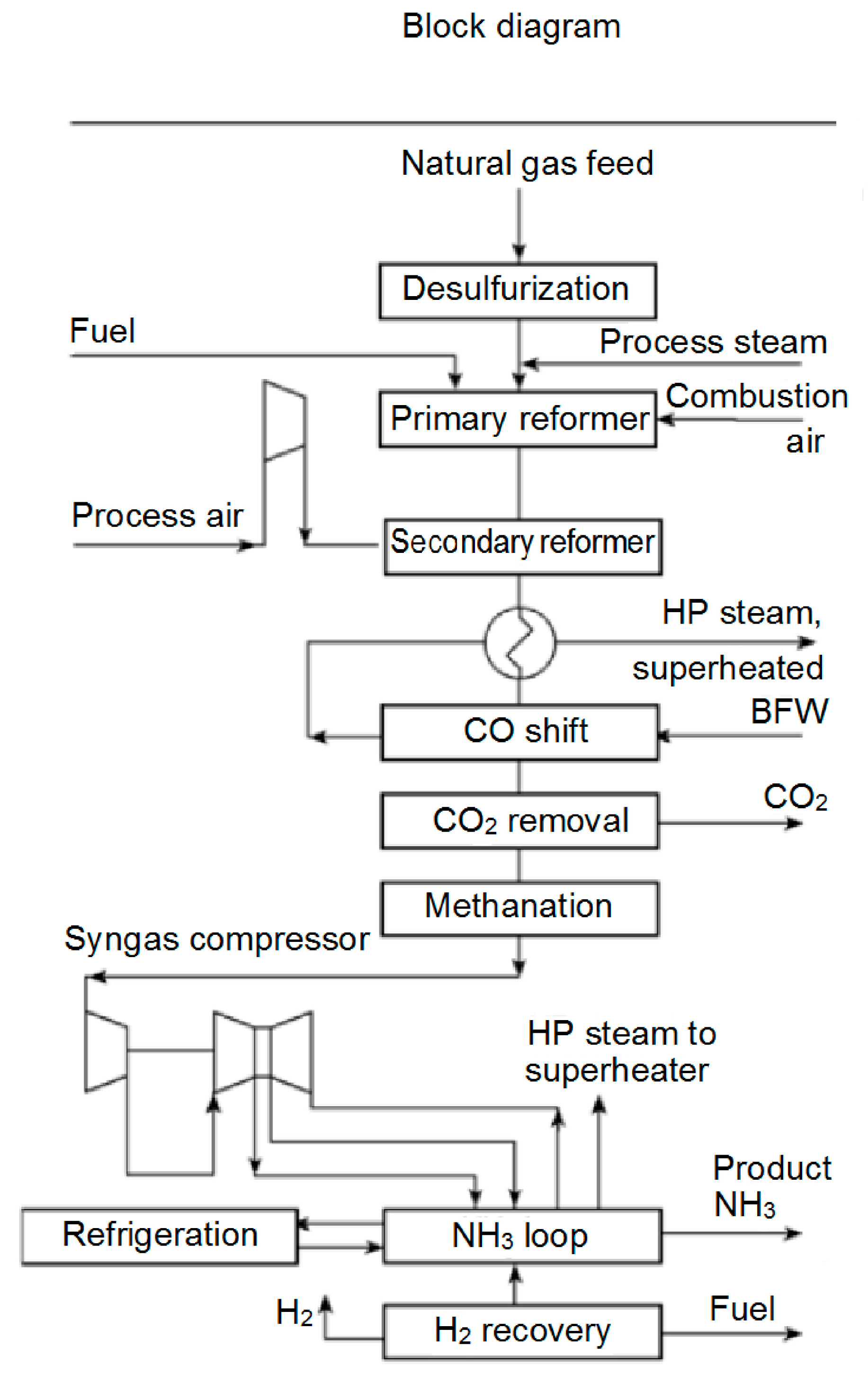
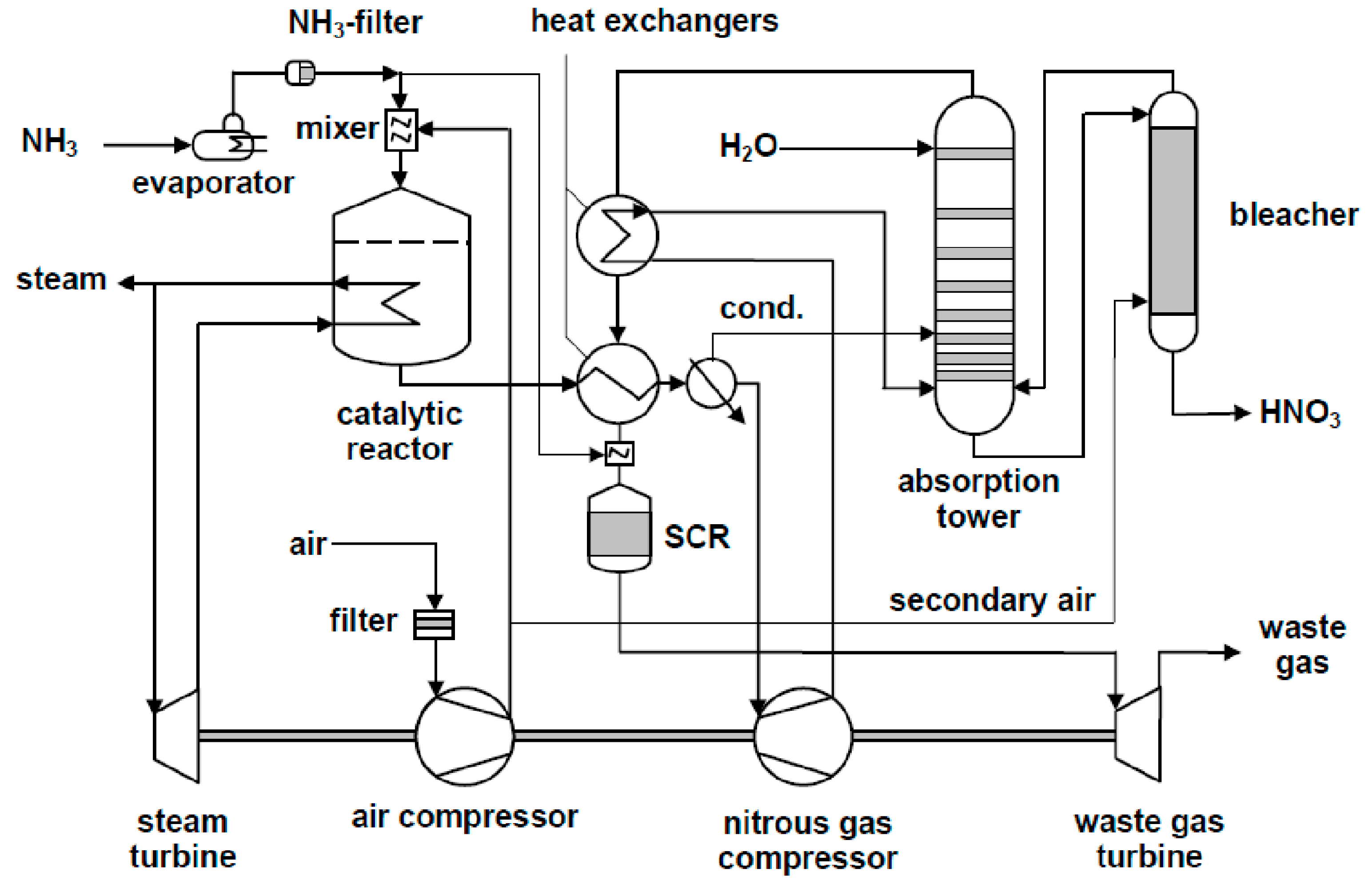
2.3. Synthesis Loop and Downstream Activities

A critical part in the energy optimization of the plasma-assisted nitrogen fixation processes is the ASPEN design and simulation of the synthesis loop, or more precisely the reactor scheme itself. The performance of the plasma reactor will closely influence the capability of the relevant upstream and downstream activities. To elaborate, as shown in Figure 11, the synthesis gas (nitrogen/hydrogen feed), which is obtained from the methanation section at a temperature of 280 °C and pressure of 26.5 bar, undergoes further compression to approximately 300 bar prior to entering the ammonia synthesis loop [48]. The generated ammonia exits the synthesis loop at a temperature around 440 °C and pressure of 284 bar and, then, is directed to the refrigeration system with starting operating conditions of 15 °C and 275 bar. Upon the same design concept and feedstock properties, replacing the conventional ammonia converters in the synthesis loop with a single or a series of plasma reactor operating at 1 bar and 25 °C is likely to reduce energy costs at a first stage, as the compression and preheat requirements of the reactor feed will be remarkably lower. However, this point alone is not able to provide a clear view of the process energy efficiency, since it should be considered in combination with the electricity consumption of plasma reactor, which will play a contributory role and request considerable attention in terms of its optimization.
In addition to the power consumption of the plasma reactor, the ammonia conversion rate will also influence the overall energy savings. The maximum conversion rate for plasma-assisted ammonia synthesis in DBD reactor reported in literature is 12.6% (under 180 °C and 1 bar) compared to 24% of the conventional one [49]. This implies a re-conceptualization of the established downstream processes for the reason that more quantity of unreacted reactants will be recycled in the synthesis loop and, thereby, larger heat transfer areas of the heat exchangers and higher capacity of compressors and flash tanks will be required [50].
Figure 11. Schematic overview of ammonia synthesis process. Adapted with permission from [51]. Copyright 2006, Wiley-VCH Verlag GmbH & Co. KGaA.
Processes 02 00694 g011
On the other hand, nitric acid synthesis is energy efficient and is consolidated upon three major reactions: (a) ammonia combustion, (b) oxidation of nitric oxide, and (c) absorption of nitric oxide in water (Figure 12) [52]. The process demonstrates a net energy export of approximately 1.6 GJ/t HNO3. attributed to the heat recovery from the absorption tail gases and the exothermic oxidation of ammonia which takes place at temperatures and pressures between 840–950 °C and 1–8 bar, respectively [53]. The NO gas generated by ammonia combustion is cooled to 20–30 °C and driven to the absorption column where its oxidation and absorption in water will take place. Based on these operating conditions and assuming the replacement of the ammonia oxidation by a plasma-assisted nitric oxide process operating at ambient temperature and pressure, the energy profile of the entire process seems to drastically change, as the nitric oxide reaction is highly endothermic and the NO conversion rate is still lower than the conventional one. Although energy savings from avoiding cooling the plasma-produced NO for the absorption section seem to dominate at a first stage, the lower conversion will lead to a redesign of the downstream activities and, thereby, to a different energy profile for the plasma process as compared to the conventional one. Consequently, a pinch analysis will be conducted for the optimal ASPEN design model of the plasma-assisted nitric acid synthesis so as to minimize energy consumption and to enable a complete benchmark with the conventional route.
In both cases of plasma-assisted nitrogen fixation, the initial ASPEN model will be established and optimized based on the conventional operating conditions. However, after completing this step, different design scenarios that enhance the energy performance of plasma-assisted nitrogen fixation will be applied since the final aim of the MAPSYN project is not to achieve comparable industrial production capacities, but to develop processes performing at a maximum efficiency based on their inherent characteristics and operational requirements.
Figure 12. Process flow diagram of dual pressure nitric acid synthesis. Reprinted with permission from [53]. Copyright 2001, Umweltbundesamt-Federal Environment Agency Austria.
Processes 02 00694 g012

3. Conclusions

As it can be concluded from the above, there are three major design parameters that will play a critical role in the energy performance of plasma-assisted nitrogen fixation: (I) the integration of renewable energy; (II) the power supply system of plasma reactors; and (III) process design of industrial plasma-assisted nitrogen fixation. The integration of renewable energy sources is one of the most influential factors in enhancing the sustainability profile of the selected processes. Valid scenarios, for example, for the utilization of solar and wind energy will be developed and incorporated in the process design and the corresponding energy footprint will be monitored. In addition to that, the power supply system of the plasma reactors will also become a subject of profound research. The reason for this lies in the fact that studies towards the improvement of the power delivery efficiency in the discharge plasma have been intensely identified in literature with the majority of them employing the impedance matching theory. The underlying principle of this impedance matching will be applied and tested in the plasma reactors of the MAPSYN project with a view to minimizing power losses and maximizing power delivery in plasma discharge.
Regarding the initial industrial design of the plasma-assisted ammonia and nitric acid syntheses, although it will generally follow the conventional corresponding production routes, the synthesis and downstream activities will still be subject to re-conceptualization with respect to the capability, equipment size, etc. Finally, the proposed design for the selected processes will be subjected to a multi-criteria optimization procedure with the ultimate aim of attaining long-term economic feasibility and sustainability.

Acknowledgments

This research is kindly funded by the EU project MAPSYN: Microwave, Acoustic and Plasma SYNtheses, under grant agreement no. CP-IP 309376 of the European Community’s Seventh Framework Program.

Author Contributions

Volker Hessel and Qi Wang developed the conceptual idea and defined the topic of the review paper. All authors contributed to the manuscript drafting. Aikaterini Anastasopoulou detailed the concept with the concrete contents and coordinated the writing. She also contributed to the revision of the manuscript.

Conflicts of Interest

The authors declare no conflict of interest.

References

  1. Willem, E.J.; Sutton, M.A.; Galloway, J.; Klimont, Z.; Winiwarter, W. How a Century of Ammonia Synthesis Changed the World. Nat. Geosci. 2008, 1, 636–639. [Google Scholar]
  2. Companies and Markets. Ammonia Global Market to 2020. Available online: http://www.companiesandmarkets.com/Market/Chemicals/Market-Research/Ammonia-Global-Market-to-2020/RPT1145125 (accessed on 21 February 2014).
  3. Rafiqul, I.; Weber, C.; Lehmann, B.; Voss, A. Energy Efficiency Improvements in Ammonia Production—Perspectives and Uncertainties. Energy 2005, 30, 2487–2504. [Google Scholar]
  4. International Energy Agency (IEA). Tracking Industrial Energy Efficiency and CO2 Emissions; IEA Publications: Paris, France, 2007; p. 324. [Google Scholar]
  5. Feibelman, P.J.; Stumpf, R. Comments on Potential Roles of Ammonia in a Hydrogen Economy—A Study of Issues Related to the Use of Ammonia for On-Board Vehicular Hydrogen Storage. Available online: http://www.sandia.gov/surface_science/pjf/On_NH3_roles_in_H2_economy.pdf (accessed on 21 February 2014).
  6. Lan, R.; Tao, S. Direct Ammonia Alkaline Anion-Exchange Membrane Fuel Cells. Electrochem. Solid-State Lett. 2010, 13, B83–B86. [Google Scholar]
  7. European Fertilizer Manufacturers Association (EFMA). Best Available Techniques for Pollution Prevention and Control in the European Fertilizer Industry. Booklet No. 1 of 8: Production of Ammonia; EFMA: Brussels, Belgium, 2000. [Google Scholar]
  8. Kool, A.; Marinussen, M.; Blonk, H.; Consultants, B. LCI Data for the Calculation Tool Feedprint for Greenhouse Gas Emissions of Feed Production and utilization. GHG Emissions of N, P and K Fertilizer Production; Blonk Consultants: Gouda, The Netherlands, 2012; p. 15. [Google Scholar]
  9. Bai, M.; Zhang, Z.; Bai, X.; Bai, M.; Ning, W. Plasma Synthesis of Ammonia with a Microgap Dielectric Barrier Discharge at Ambient Pressure. IEEE Trans. Plasma Sci. 2003, 31, 1285–1291. [Google Scholar] [CrossRef]
  10. Mutel, B.; Dessaux, O.; Goudmand, P. Energy Cost Improvement of the Nitrogen Oxides Synthesis in a Low Pressure Plasma. Rev. Phys. Appl. 1984, 19, 461–464. [Google Scholar] [CrossRef]
  11. Fridman, A.; Cho, Y.-I. Transport Phenomena in Plasma-Advances in Heat Transfe; Academic Press, Elsevier: Waltham, MA, USA, 2007; Volume 1, pp. 1–4. [Google Scholar]
  12. Pekárek, S. Non-Thermal Plasma Ozone Generation. Acta Polytech. 2003, 43, 47–51. [Google Scholar]
  13. Bartels, J.R. A Feasibility Study of Implementing an Ammonia Economy. Master’s Thesis, Iowa State University, Ames, IA, USA, 2008. [Google Scholar]
  14. Hessel, V.; Anastasopoulou, A.; Wang, Q.; Kolb, G.; Lang, J. Energy, Catalyst and Reactor Considerations for (near)-Industrial Plasma Processing and Learning for Nitrogen-Fixation Reactions. Catal. Today 2013, 211, 9–28. [Google Scholar] [CrossRef]
  15. Hessel, V.; Cravotto, G.; Fitzpatrick, P.; Patil, B.S.; Lang, J.; Bonrath, W. Industrial applications of plasma, microwave and ultrasound techniques: Nitrogen-fixation and hydrogenation reactions. Chem. Eng. Process. 2013, 71, 19–30. [Google Scholar] [CrossRef]
  16. Gieshoff, J.; Lang, J. Process for the Plasma-Catalytic Production of Ammonia. U.S. Patent 6471932B1, 29 October 2002. [Google Scholar]
  17. Tallaksen, J.; Reese, M. Ammonia Production Using Wind Energy. Available online: http://nh3fuel.files.wordpress.com/2013/10/nh3fcx-joel-tallaksen.pdf (accessed on 21 February 2014).
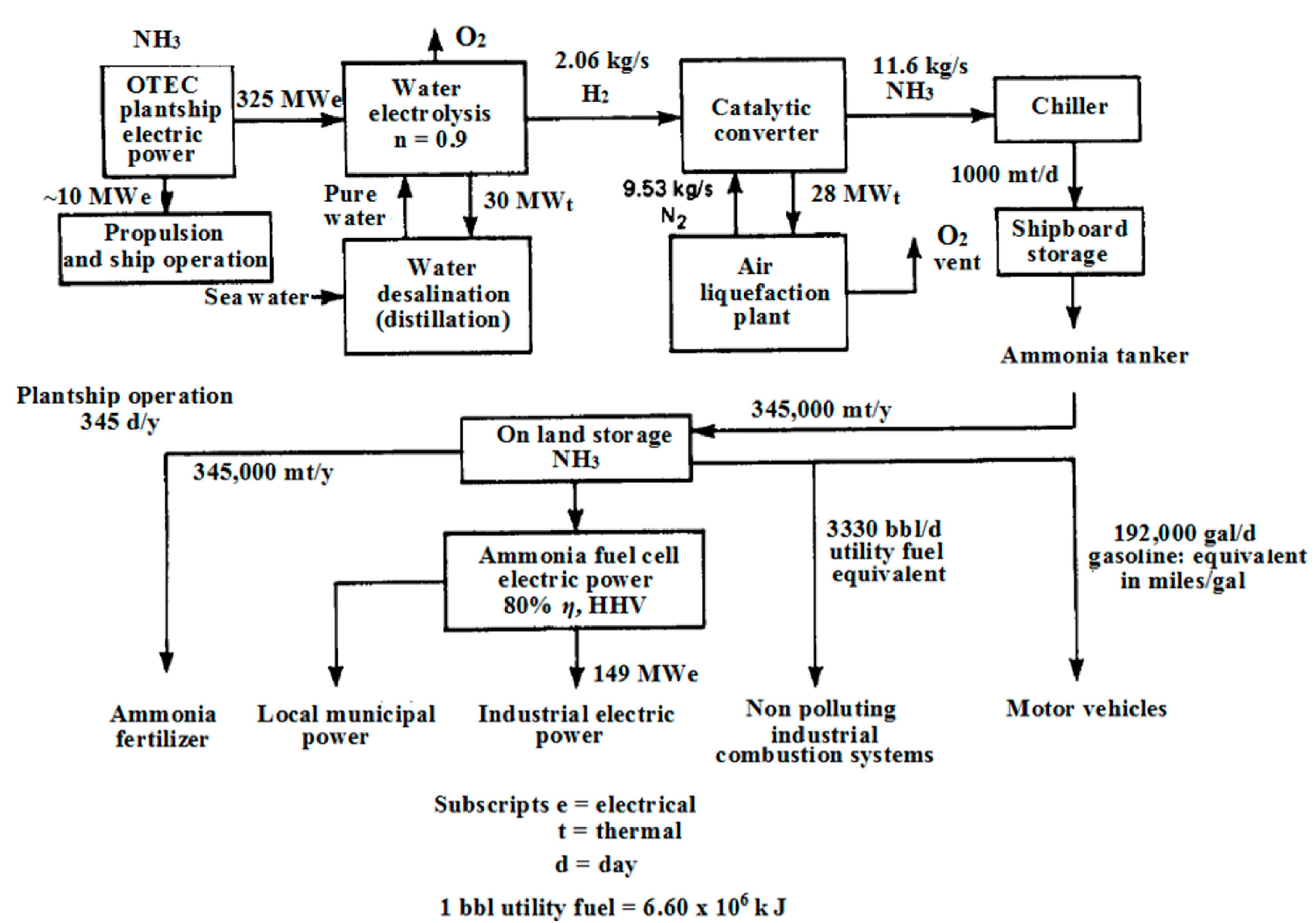
  18. Dugger, G.; Francis, E. Design of an Ocean Thermal Energy Plant Ship to Produce Ammonia via Hydrogen. Int. J. Hydrog. Energy 1977, 2, 231–249. [Google Scholar] [CrossRef]
  19. Lu, X.; McElroy, M.B.; Kiviluoma, J. Global Potential for Wind-Generated Electricity. Proc. Natl. Acad. Sci. USA 2009, 106, 10933–10938. [Google Scholar] [CrossRef]
  20. Alosaimy, A.S.; Hamed, A.M.; Balabel, A.; Mahrous, A. Experimental Investigation of Solar Hydrogen Production Unit in Taif, Saudi Arabia. Int. J. Adv. Sci. Tech. Res. 2013, 6, 61–73. [Google Scholar]
  21. Union of the Electric Industry-EURELECTRIC & VGB PowerTech. Efficiency in Electric Generation; Union of the Electricity Industry-EURELECTRIC & VGB: Brussels, Belgium, 2003. [Google Scholar]
  22. Waid, R.L. The Mini-Otec Test. In Proceedings of the OCEANS '79: Fifth Annual Combined Conference, San Diego, CA, USA, 17–19 September 1979; pp. 548–552.
  23. Avery, W.H.; Richards, D.; Dugger, G.L. Hydrogen Generation by OTEC Electrolysis, and Economical Energy Transfer to World Markets via Ammonia and Methanol. Int. J. Hydrog. Energy 1985, 10, 727–736. [Google Scholar] [CrossRef]
  24. NH3 Fuel Association. Ammonia Production Using Wind Energy. Available online: http://nh3fuelassociation.org/2013/08/28/ammonia-production-using-wind-energy/ (accessed on 21 February 2014).
  25. Ammonia Industry. Ammonia Plants: Morris, MN—University of Minnesota. Available online: http://ammoniaindustry.com/morris-mn-university-of-minnesota/ (accessed on 23 June 2014).
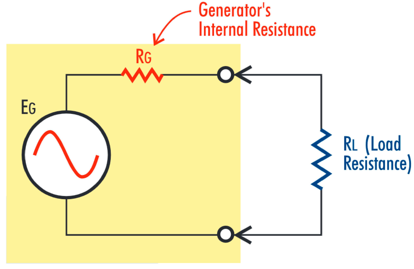
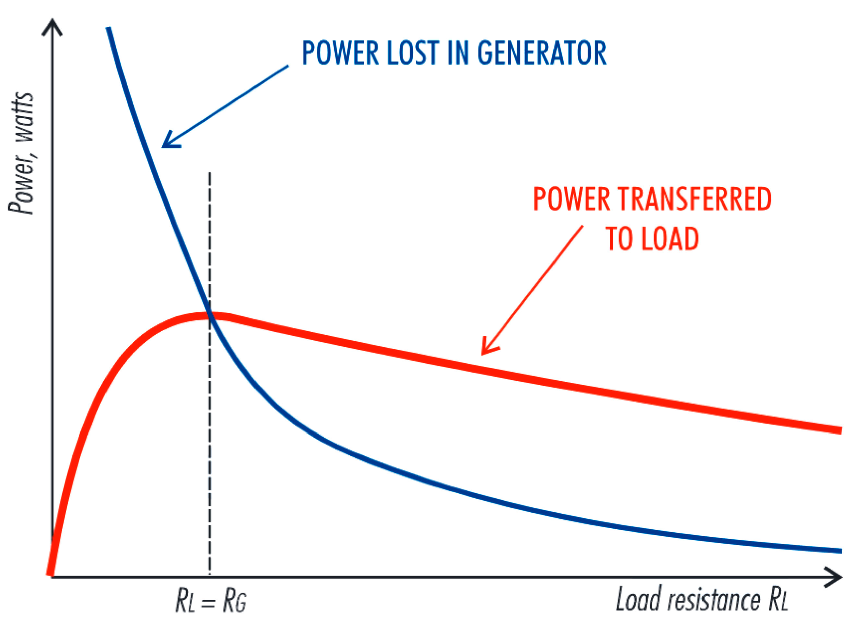
  26. Chen, Z. Impedance Matching for One Atmosphere Uniform Glow Discharge Plasma (OAUGDP) Reactors. IEEE Trans. Plasma Sci. 2002, 30, 1922–1930. [Google Scholar] [CrossRef]
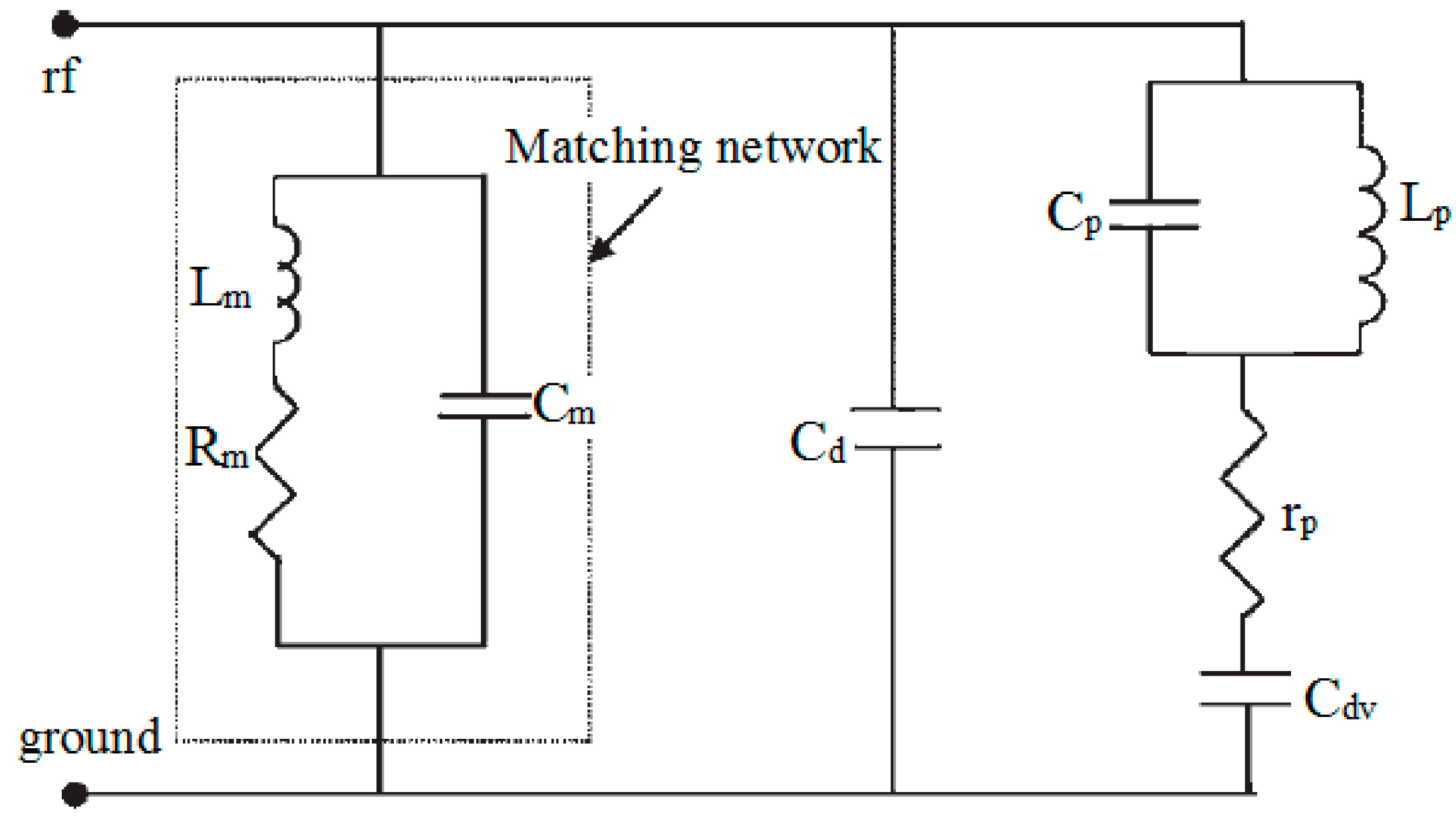
  27. Spiliopoulos, N.; Mataras, D.; Rapakoulias, D.E. Power Dissipation and Impedance Measurements in Radio-Frequency Discharges. J. Vac. Sci. Technol. A 1996, 14, 2757–2765. [Google Scholar] [CrossRef]
  28. Diatczyk, J.; Komarzyniec, G.; Stryczewska, H.D. Power Consumption of Gliding Arc Discharge Plasma Reactor a B. Int. J. Plasma Environ. Sci. Technol. 2011, 5, 12–16. [Google Scholar]
  29. Holub, M.; Kalisiak, S.; Jakubowski, T.; Balcerak, M. Power Electronic Supply Systems for Non-Thermal Plasma Sources. In Proceedings of the XVIII International Conference on Gas Discharge and Their Applications (GD2010), Greifswald, Germany, 5–10 September 2010.
  30. Sheykhrajeh, S.Z. Flexible High Voltage Pulsed Power Supply for Plasma Applications. Ph.D. Thesis, Queensland University of Technology, Brisbane, QLD, Australia, 2011. [Google Scholar]
  31. Van Dijk, J.; Kroesen, G.M.W.; Bogaerts, A. Plasma Modelling and Numerical Simulation. J. Phys. D 2009, 42, 190301. [Google Scholar]
  32. Jaycar Electronics Group. Impedance Matching : A primer. Available online: http://www.jaycar.com.au/images_uploaded/impmatch.pdf (accessed on 21 February 2014).
  33. Singh, K.P.; Roy, S. Impedance Matching for an Asymmetric Dielectric Barrier Discharge Plasma Actuator. Appl. Phys. Lett. 2007, 91, 081504. [Google Scholar] [CrossRef]
  34. Zito, J.C.; Arnold, D.P.; Duscher, R.J.; Roy, S. Investigation of Impedance Characteristics and Power Delivery for Dielectric Barrier Discharge Plasma Actuators. In Proceedings of the 48th AIAA Aerospace Sciences Meeting Including the New Horizons Forum and Aerospace Exposition, Orlnado, FL, USA, 4–7 January 2010; pp. 1–17.
  35. Kriegseis, J.; Grundmann, S.; Tropea, C. Power Consumption, Discharge Capacitance and Light Emission as Measures for Thrust Production of Dielectric Barrier Discharge Plasma Actuators. J. Appl. Phys. 2011, 110, 013305. [Google Scholar] [CrossRef]
  36. Ebato, S.; Ogino, Y.; Ohnishi, N. Computational Study of Discharge Processes in DBD Plasma Actuators. J. Space Technol. Sci. 2011, 25, 19–33. [Google Scholar]
  37. Kriegseis, J.; Möller, B.; Grundmann, S.; Tropea, C. Capacitance and Power Consumption Quantification of Dielectric Barrier Discharge (DBD) Plasma Actuators. J. Electrost. 2011, 69, 302–312. [Google Scholar] [CrossRef]
  38. Pipa, A.V.; Koskulics, J.; Brandenburg, R.; Hoder, T. The Simplest Equivalent Circuit of a Pulsed Dielectric Barrier Discharge and the Determination of the Gas Gap Charge Transfer. Rev. Sci. Instrum. 2012, 83, 115112. [Google Scholar] [CrossRef]
  39. Tran, N.D.; Sasaki, T.; Kikuchi, T.; Harada, N. Optimization Input Power to Obtain the Stable Annealing Conditions of a Plasma Annealing System at Atmospheric Pressure. J. Plasma Fusion Res. Ser. 2010, 9, 503–508. [Google Scholar]
  40. Dai, J.; Hao, R.; You, X.; Sun, H.; Huang, X.; Li, Y. Modeling of Plasma Arc for the High Power Arc Heater in MATLAB. In Proceedings of the 5th IEEE Conference on Industrial Electronics and Applications, Taichung, Taiwan, 15–17 June 2010; pp. 463–468.
  41. Tseng, K.-J.; Wang, Y.; Vilathgamuwa, D.M. An Experimentally Verified Hybrid Cassie-Mayr Electric Arc Model for Power Electronics Simulations. IEEE Trans. Power Electron. 1997, 12, 429–436. [Google Scholar] [CrossRef]
  42. Jaroszyński, L.; Stryczewska, H.D. Computer Simulation of the Electric Discharge in Glidarc Plasma Reactor. In Proceedings of the 3rd International Conference: Electromagnetic devices and processes in environment protection ELMECO-3, Naleczow, Poland, 4–6 June 2000.
  43. Valdivia-Barrientos, R.; Pacheco-Sotelo, J.; Pacheco-Pacheco, M.; Benítez-Read, J.S.; López-Callejas, R. Analysis and Electrical Modelling of a Cylindrical DBD Configuration at Different Operating Frequencies. Plasma Sources Sci. Technol. 2006, 15, 237–245. [Google Scholar] [CrossRef]
  44. Liu, S.; Neiger, M. Electrical Modelling of Homogeneous Dielectric Barrier Discharges under an Arbitrary Excitation Voltage. J. Phys. D Appl. Phys. 2003, 36, 3144–3150. [Google Scholar] [CrossRef]
  45. Stryczewska, H.D.; Janowski, T.; Jaroszyński, L. Mathematical Model of the Non-Thermal Plasma Reactor. In Proceedings of the IV International Workshop on Advanced Plasma Tools and Process Engineering, Millbrae, CA, USA, 26–27 May 1998.
  46. Gustavsson, N. Evaluation and Simulation of Black-Box Arc Models for High Voltage Circuit-Breakers. Master’s Thesis, Linkoping University, Linkoping, Sweden, 2004. [Google Scholar]
  47. Nitu, S.; Nitu, C.; Mihalache, C.; Anghelita, P.; Pavelescu, D. Comparison between Model and Experiment in Studying the Electric Arc. J. Optoelectron. Adv. Mater. 2008, 10, 1192–1196. [Google Scholar]
  48. Russamee, N. Simulation and Design of Ammonia Process from Natural Gas Reforming. Master’s Thesis, Kasetsart University, Bangkok, Thailand, 2009. [Google Scholar]
  49. Ruan, R.; Deng, S.; Le, Z.; Chen, P. Non-Thermal Plasma Synthesis of Ammonia. WO Patent 2009025835 A1, 26 February 2009. [Google Scholar]
  50. Thyssenkrupp Uhde. Ammonia. Available online: http://www.thyssenkrupp-uhde-asia-pacific.com/fileadmin/documents/brochures/0a2d5391-b166-484d-847d-3cbfd941f06b.pdf (accessed on 21 February 2014).
  51. Appl, M. Ammonia. In Ullmann's Encyclopedia of Industrial Chemistry; Wiley-VCH Verlag GmbH & Co. KGaA: Weinheim, Germany, 2006; p. 85. [Google Scholar]
  52. Thyssenkrupp Uhde. Nitric acid. Available online: http://www.thyssenkrupp-uhde-asia-pacific.com/fileadmin/documents/brochures/cc0d66ab-c015-4512-8c70-1dd5d2917b9e.pdf (accessed on 21 February 2014).
  53. Wiesenberger, H. State-of-the-Art for the Production of Nitric Acid with Regard to the IPCC Directive; Umweltbundesamt-Federal Environment Agency Austria: Vienna, Austria, 2001; p. 66. [Google Scholar]

