Article

Numerical Study on the Influence of Micro-Geometric Characteristics of Scrapers on Flow Field Distribution in Wiped-Film Molecular Distillers

School of Chemical Engineering, Northwest University, Xi’an 710069, China
*
Author to whom correspondence should be addressed.
These authors contributed equally to this work.
Processes 2026, 14(9), 1447; https://doi.org/10.3390/pr14091447
Submission received: 15 March 2026 / Revised: 6 April 2026 / Accepted: 27 April 2026 / Published: 29 April 2026
(This article belongs to the Section Chemical Processes and Systems)

Abstract

Conventional wiped-film molecular distillers (WFMDs) often show limited hydrodynamic renewal and mixing when processing high-viscosity materials because of liquid pooling and weak secondary flow. This study investigates a novel grooved scraper design for a wiped-film molecular distiller handling an ethylene glycol/glycerol mixture (42.0 mol% ethylene glycol; density 1196.0 kg/m3; dynamic viscosity 0.222 Pa·s), used here as a representative high-viscosity, heat-sensitive system. Three-dimensional multiphase CFD simulations were performed to examine the combined effects of groove width (2.0–10.0 mm) and scraper tip angle (30–75°) on flow behavior. The results show that a groove width of 7.0 mm increases vorticity gain by 9% and wall shear stress gain by 20% relative to the inline scraper baseline. The grooved geometry generates periodic shear disturbances, promotes radial secondary flow, and strengthens turbulent mixing. A balance between radial mixing enhancement and axial transport continuity is required. Among the tested angles, a tip included angle of 45° produces the highest average vorticity magnitude and more coherent vortex structures. These findings clarify the hydrodynamic regulation mechanism of scraper micro-geometry and support its use as a process-intensification strategy for distiller parameter selection.

1. Introduction

Wiped-film molecular distillers (WFMDs) are well suited for processing high-viscosity and heat-sensitive materials because they combine short residence time, gentle heating, and mechanical surface renewal. Compared with conventional vacuum distillation and non-mechanical thin-film evaporators, WFMDs provide stronger liquid-film control through scraper-driven renewal, making them widely used in polymer devolatilization, fine chemicals, food, and pharmaceutical processing [1,2,3,4,5]. However, their actual performance depends strongly on scraper–fluid interaction, and the theoretical advantages of WFMDs are often not fully realized because of the complex internal hydrodynamics and increasingly stringent industrial requirements [6]. As early as 1959, Kern [7] emphasized that mechanically assisted fluid flow is far more complex than idealized theory and depends critically on the interaction between the scraper and the fluid. Subsequently, Bott [8] experimentally demonstrated the influence of scraper rotation and fluid properties on wiped-film operation.
From a practical viewpoint, a persistent challenge is maintaining a stable and continuous thin film under strong mechanical forcing, especially for high-viscosity feeds. In falling film evaporators, liquid film rupture is a key factor leading to fouling formation, so maintaining a fully wetted tube wall is a core criterion for design and operation [9]. To address this issue, the pioneering work of Komori [10] et al. revealed a fundamental flow defect inside the equipment: there is a serious stratification between the liquid pool formed at the leading edge of the scraper and the wall film, and the mass exchange between the two is extremely inhibited. This causes most of the materials to flow directly downward in the liquid pool, bypassing the key wall evaporation zone, resulting in uneven residence time and low efficiency. In the remainder of this paper, this stratification-driven suppression of pool–film exchange is referred to as “mixing inhibition.” This mixing inhibition at the micro level is the root cause of poor macro performance. The research of Appelhaus [11] further pointed out that poor mixing will directly lead to the deterioration of wetting behavior, eventually resulting in liquid film rupture and dry zone formation. Hydrodynamically, this phenomenon is manifested as unstable stream dynamics [12], thereby significantly reducing the effective transfer area. Recent studies by Julio [13] et al. have further confirmed that this stratification phenomenon is more serious when handling high-viscosity fluids, and gas entrainment between the liquid pool and the liquid film will further hinder mixing.
To conduct an in-depth study on this complex flow field problem, computational fluid dynamics (CFD) numerical simulation has become a mainstream research tool due to its ability to overcome the difficulties of experimental measurement. The experimental characterization of flow regimes and wall shear rates in scraped-surface heat exchangers (SSHEs) by Dumont et al. [14] provided fundamental benchmarks for near-wall shear intensity in rotating film systems, and subsequent three-dimensional CFD studies by Yataghene et al. [15,16] demonstrated that fully resolved 3D models are necessary to capture the local shear-rate distribution and thermal behavior in SSHEs with sufficient fidelity. In parallel, Pawar and Thorat [17] performed CFD analysis of the agitated thin-film evaporator and systematically quantified the influence of process parameters on flow pattern and liquid holdup, confirming the reliability of CFD for rotating film systems. Building on these foundations, three-dimensional multiphase CFD methods [18,19] provide a powerful means to reveal the complex flow details inside wiped-film evaporators. Relevant studies [17,20] have mainly focused on the internal mixing mechanism of fluids, liquid holdup, residence time distribution, etc., and have paid attention to the impacts brought by changes in internal process parameters of the evaporator, all proving the reliability of CFD for analyzing such flow-dominated separation systems. The experimental investigation of residence-time behavior in WFMDs by Jasch et al. [21] further demonstrated that scraper geometry and rotational conditions exert significant influence on axial transport and material contact time, establishing residence time as a key process constraint that any geometry modification must satisfy. More broadly, CFD has also been extensively used in other process-intensification equipment, such as distillation column stages and stirred tanks, where hydrodynamics, turbulence, and phase-contact behavior can be quantified numerically and used to guide design and operation [22,23,24]. To overcome the problem of poor liquid pool mixing, some researchers have used CFD simulation tools to study the flow field distribution inside distillers and actively enhanced radial mixing through innovative scraper structures. Early explorations, such as the multi-section scraper proposed by McKenna [25], aimed to force fluid remixing by periodically disrupting the liquid pool. This idea was further developed in Zhang’s [26] recent research on staggered rotors. Further studies have focused on different types of scraper designs; for example, Vishnu [27] et al. successfully applied roller-type scrapers with internal condensers for efficient solvent recovery. These studies collectively point to a key scientific question, as clearly stated by Gu [28]: the structure of the scraper directly determines the three-dimensional shape of the liquid film, and the liquid film shape is the core factor affecting the final evaporation performance. However, most existing structural modifications emphasize macro-scale regulation of the liquid pool, while quantitative understanding of how scraper surface micro-geometry regulates secondary flow and mixing remains limited.
From a hydrodynamic perspective, the generation of secondary flow requires the application of a continuous force outside the main flow direction, which can be achieved by introducing periodic geometric mutations on the scraper surface. This principle has been verified in other heat- and mass-transfer equipment; for instance, Tarokh et al. [29] significantly enhanced internal convective heat transfer by installing vortex generators in two-phase closed thermosyphons, and Al-Hassan et al. [30] demonstrated that split-and-recombine micro-structured geometries effectively generate transverse vorticity and improve mixing in viscous flows. At the microscale, researchers have also induced turbulent flow by changing structural parameters to achieve efficient mixing [31]. Mechanistically, the grooved structure on the scraper surface can generate a periodic pressure gradient and shear stress distribution during rotation, and this non-uniform force field distribution is the key to inducing stable secondary flow. The existence of grooves causes the fluid to undergo a periodic compression-release process when in contact with the scraper: at the leading edge of the groove, the fluid is subjected to sudden compression; while inside the groove, the fluid obtains a temporary expansion space. This periodic change in geometric constraints generates a velocity component perpendicular to the main flow direction in the flow field, thereby forming continuous radial eddies. This mechanism is similar to the Dean vortices induced by periodic obstacles in pipes.
However, although the grooved structure has been proven effective, there is still a lack of systematic quantitative research on how the key geometric characteristic parameter of groove width regulates the evolution of secondary flow and its nonlinear coupling relationship with mixing intensity. Theoretically, the groove width determines the spatial scale of the compression-release cycle, thereby affecting the development degree of secondary flow. An excessively narrow groove may cause the disturbance to be confined inside the groove, failing to form large-scale vortex structures, while an excessively wide groove may allow the fluid to pass directly through, weakening the effective control of the fluid by the scraper. Despite these advances, a clear and systematic research gap remains. Although grooved or structured scraper geometries have been proposed as a means to improve mixing over conventional inline scrapers, no published study has quantitatively and systematically examined how the two key micro-geometric parameters—groove width and scraper tip included angle—co-regulate the development of secondary flow, the three-dimensional vortex topology, and wall-renewal intensity specifically under WFMD operating conditions with high-viscosity feeds. In particular, the nonlinear coupling between groove width and secondary-flow scale—including the existence of an effective groove-width window within which rotational mechanical energy is most efficiently converted into radial vortex kinetic energy—has not been established. Nor has the mechanically matched configuration of normal thrust and tangential shear at the scraper tip—the configuration that yields peak vortex coherence and mixing intensity—been identified through systematic simulation. This gap limits the ability to formulate evidence-based micro-geometry design criteria for process intensification in WFMDs. Accordingly, to fill this gap, the central objective of this work is to quantify how groove micro-geometry controls secondary-flow development and mixing-inhibition relief under WFMD operating conditions. Inspired by the vortex-generator analogy demonstrated in related equipment [29,30], this paper proposes and systematically studies a novel scraper design with internal grooves for the first time. We aim to verify that grooves, as precise spatial regulation units, can efficiently convert the kinetic energy of scraper rotation into secondary eddies perpendicular to the main flow direction, thereby overcoming the mixing inhibition problem proposed by Komori et al.
Based on a three-dimensional two-phase flow model, this study decouples and quantitatively investigates the synergistic effects of groove width and scraper tip angle on the turbulent characteristics of the flow field and hydrodynamic mixing-related performance through high-precision CFD simulations. It establishes design criteria from micro-geometry to macro-scale hydrodynamic behavior, providing a theoretical basis for subsequent distiller design and parameter selection. The remainder of this paper is organized as follows: Section 2 describes the numerical model and evaluation system, Section 3 presents and discusses the flow-field results for different scraper micro-geometries, and Section 4 summarizes the main conclusions.

2. Numerical Methods and Evaluation System

2.1. Physical Model

It is important to note at the outset that all simulations in this work are performed in a fully three-dimensional computational domain; no two-dimensional or axisymmetric simplification is adopted at any stage. This choice is physically essential for two reasons. First, the discrete scraper units and the groove micro-geometry introduce azimuthally non-uniform boundary conditions that fundamentally break the rotational symmetry of the domain; a 2D or axisymmetric model cannot represent these boundary conditions faithfully and would suppress the very azimuthal variations that drive the process-intensification mechanisms investigated here. Second, the radial secondary vortices—coherent three-dimensional structures whose formation, spatial scale, and axial connectivity govern pool–film exchange and constitute the central mechanism of interest—cannot be resolved in a two-dimensional formulation. These points are consistent with the findings of Zhang et al. [26], who demonstrated that 3D CFD is necessary to capture the local shear-rate topology and vortex-dominated flow behavior in rotating scraped-surface and WFMD geometries with adequate fidelity.
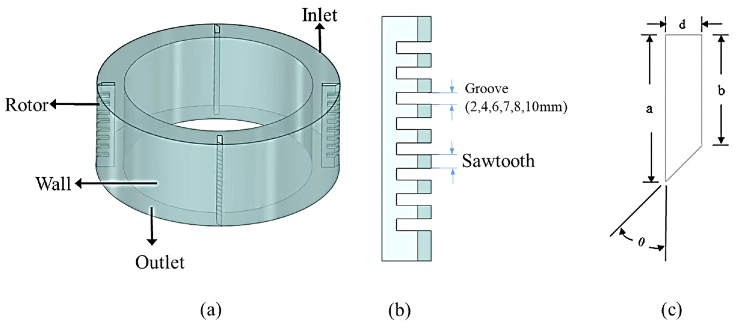
This study focuses on the influence of the local micro-geometric structure of the scraper on the flow field. Figure 1a shows the three-dimensional geometric model of the wiped-film molecular distiller. The outer wall of the evaporator serves as the heating wall with an outer diameter of 400.0 mm and a temperature set to 350.0 K; the inner wall acts as the condensation surface with an inner diameter of 310.0 mm and a temperature set to 240.0 K.
The grooved scraper geometry investigated in this study was constructed based on the following design assumptions: (i) the groove is introduced by removing material symmetrically from the scraper body in the axial direction, without altering the outer envelope dimensions (long side a = 29.2 mm, short side b = 21.2 mm, thickness d = 8.0 mm) or the tip-to-wall clearance (0.8 mm), so that the grooved design is a direct derivative of the baseline inline scraper and comparisons between the two are geometrically consistent; (ii) the groove cross-section is rectangular, with a fixed depth equal to the sawtooth radial width of 8.0 mm, ensuring that the groove fully penetrates the scraper in the radial direction and creates a well-defined expansion cavity for fluid interaction; (iii) the sawtooth tip geometry—including the tip included angle θ —is maintained constant across all groove-width cases, so that the parametric study of groove width W is a true single-variable investigation decoupled from tip-angle effects; (iv) the sawtooth width is fixed at 8.0 mm for all cases, and the number of groove–sawtooth pairs along the scraper axial length is determined by the integer ratio of scraper axial length to the combined pitch (groove width + sawtooth width); and (v) the tip-to-wall clearance is fixed at 0.8 mm across all parametric cases to isolate the effect of groove micro-geometry. Based on these assumptions, the geometric construction procedure follows five steps: Step 1—define the baseline inline scraper envelope with dimensions a, b, d and clearance 0.8 mm; Step 2—fix the sawtooth width at 8.0 mm and specify the tip included angle θ; Step 3—assign groove width W at the desired discrete level (2.0, 4.0, 6.0, 7.0, 8.0, or 10.0 mm) and compute the number of groove–sawtooth pairs; Step 4—extrude the rectangular groove profile to the full groove depth (8.0 mm) along the radial direction to generate the 3D grooved scraper solid; Step 5—import the CAD geometry into ANSYS 2022R1 for meshing and domain assembly. Figure 1b illustrates the resulting scraper structure with groove width W, sawtooth width, and groove depth labeled.
To systematically investigate the effect of groove width, the sawtooth width is kept constant, with both the axial width and radial width being 8.0 mm. As a key variable, the groove width is set at six levels: 2.0 mm, 4.0 mm, 6.0 mm, 7.0 mm, 8.0 mm, and 10.0 mm, as shown in Figure 1b. The groove-width range and the discrete groove-width levels were established based on the characteristic geometric length scales of the scraper and the need to cover representative narrow, intermediate, and wide groove regimes. The lower bound of 2.0 mm represents a narrow groove that still forms a distinct cavity relative to the wall clearance and can be resolved reliably in the numerical mesh, while the upper bound of 10.0 mm avoids an excessively wide cavity that would weaken geometric confinement and reduce scraping effectiveness. The intermediate values of 4.0 mm, 6.0 mm, 7.0 mm, and 8.0 mm bracket the characteristic sawtooth width of 8.0 mm and provide refined resolution near the groove scale where secondary-flow development is expected to change most sensitively. As the second key variable, the scraper tip included angle θ is varied from 30.0° to 75.0° at four representative levels (30.0°, 45.0°, 60.0°, and 75.0°). This interval was selected to span acute, baseline, and obtuse tip configurations that meaningfully shift the balance between normal thrust (squeezing) and tangential shear at a fixed tip-to-wall clearance (0.8 mm), while avoiding extreme angles that would be impractical for stable scraping. The definition of the main geometric parameters of the scraper is presented in Figure 1c: the length of the long side of the scraper, a = 29.2 mm, the length of the short side, b = 21.2 mm, and the thickness of the scraper, d = 8.0 mm. Under the baseline condition, the scraper tip angle θ is set to 45.0°, and to ensure effective film scraping while avoiding mechanical wear, the gap between the front end of the scraper and the heating surface is kept constant at 0.8 mm. Figure 1, therefore, defines the computational domain and the key scraper micro-geometric parameters used in the subsequent parametric exploration. Table 1 summarizes the scraper dimensions and the investigated geometric parameter ranges used in this study. For all comparative ‘gain’ analyses in Section 3, the baseline case is defined as the conventional inline scraper with no groove (W = 0.0 mm), while keeping the same scraper dimensions (a = 29.2 mm, b = 21.2 mm, d = 8.0 mm), tip-to-wall clearance (0.8 mm), and baseline tip angle ( θ = 45.0°) as defined in Figure 1c and Table 1.

2.2. Boundary Conditions and Solution Settings

The liquid mixture is treated as incompressible; under WFMD vacuum operation, the thermodynamic driving environment is primarily set by the imposed thermal boundaries (heating wall and condensing surface temperatures) and the operating pressure level. In this work, the CFD model is used to resolve the hydrodynamics and interface renewal, while thermodynamic conditions are specified as operating inputs to support the interpretation of the hydrodynamic intensification performance. Considering the gas-liquid two-phase flow, the VOF (Volume of Fluid) multiphase flow model, which is used to track the movement of interfaces between different fluid phases, is adopted. The VOF method has been proven to be a reliable tool in rotating thin-film evaporation [32] and centrifugal short-path distillation [33]. This method achieves dynamic interface tracking by solving the momentum equation and the phase-fraction transport equation, where the phase-fraction transport equation is retained here as the governing equation required by the VOF model for interface tracking rather than as an explicit model of interphase mass-transfer kinetics.
        α l + α v = 1
In the equation, α l   and α v represent the volume fractions of the liquid phase and the gas phase, respectively. The mixture density is expressed as:
ρ = α l ρ l + α v ρ v
In the equation, ρ l and ρ v are the liquid density and the gas density, respectively.
The simulation uses an ethylene glycol/glycerol mixture (42.0 mol% ethylene glycol) as a representative high-viscosity, heat-sensitive surrogate for vacuum wiped-film molecular distillation. At 20.0 °C, the mixture density is ρ = 1196.0 kg/m3 and the dynamic viscosity is μ = 0.222 Pa·s. These thermophysical properties were estimated using Aspen V10 Plus process simulation software (NRTL thermodynamic property model), which has been widely validated for binary glycol/glycerol systems across a range of compositions and temperatures. The estimated values are consistent with the expected property range for this mixture composition reported in the open literature. In the present study, the composition and rotational speed were fixed to isolate the hydrodynamic effects of groove width and scraper tip angle under a representative baseline operating condition.
The ethylene glycol/glycerol binary mixture at 20.0 °C and the present composition (42.0 mol% ethylene glycol) is a Newtonian fluid: both pure components are well-characterized Newtonian liquids across a wide temperature and shear-rate range. The constant-viscosity specification adopted in this work is therefore consistent with the Newtonian rheology of the mixture and does not introduce rheological modeling error. The viscosity does, however, depend strongly on temperature; in the present model, the liquid viscosity is specified as a constant at the reference temperature of 20.0 °C ( μ = 0.222 Pa·s), and temperature-dependent viscosity variation is not considered. This simplification is appropriate for the present study, which focuses on hydrodynamic process intensification under a representative isothermal baseline condition rather than on coupled heat-transfer or evaporation performance prediction. The effect of temperature-dependent viscosity on secondary-flow development and mixing intensity is acknowledged as a limitation of the current model and is identified as a direction for future work in Section 4. The mixture is introduced at the inlet as a mass-flow inlet with a mass flow rate of 0.15 kg/min, and a pressure outlet boundary condition is applied at the outlet with the pressure set to 15 Pa. The Single Reference Frame (SRF) model is used to realize the rotational motion. The fluid region rotates at a speed of 120.0 r/min, and the wall rotates at the opposite angular velocity relative to the rotating coordinate system to simulate the actual movement of the scraper. All walls adopt the no-slip boundary condition. Table 2 defines the working-mixture composition and the fixed operating conditions used for all simulations, while the different working conditions discussed in Section 3 refer to the scraper-geometry cases defined in Section 2.1.
The RNG k ε turbulence model is adopted in this study for the following reasons. First, the present flow is characterized by scraper-driven rotation, pronounced streamline curvature near the tip and groove edges, and localized high-strain zones—conditions for which the RNG k ε model is specifically suited. Unlike the standard k ε model, the RNG k ε formulation incorporates an analytically derived correction term R ε that accounts for the effects of rapid strain rates and streamline curvature on the dissipation rate, yielding improved accuracy in swirling and strongly rotating flows without requiring full near-wall resolution. Second, alternative models were considered but found unsuitable for the present parametric study: the standard k ε model overestimates eddy viscosity in rapidly strained regions and would artificially suppress the groove-induced secondary vortices; the SST k ω model requires y+~1, which is inconsistent with the standard wall function approach adopted here; and LES is computationally prohibitive for the ten-case parametric study. Third, the RNG k ε model has been independently validated in directly analogous rotating film systems: Xiang and Xu [34] demonstrated its superiority over the standard k ε model in wiped-film molecular distillers; Yataghene et al. [15,16] confirmed good agreement with experimental wall shear data in scraped-surface heat exchangers; and Pawar and Thorat [17] validated it against flow pattern measurements in agitated thin-film evaporators. The known limitation of this model in strongly separated flows is acknowledged, and higher-fidelity closures such as RSM or LES are recommended for future detailed vortex breakdown studies.
The governing equations are as follows:
Turbulent Kinetic Energy Equation (k Equation):
  ρ k t + ρ k u i x i = x j α k μ e f f k x j + G k + G b ρ ε Y M + S k
Dissipation Rate Equation (ε Equation):
ρ ε t + ρ ε u i x i = x j α ε μ e f f ε x j + C 1 ε ε k G k + G 3 ε G b C 2 ε ρ ε 2 k R ε + S ε
In the equation, G k is the production term of turbulent kinetic energy k caused by the average velocity gradient, G b is the production term of turbulent kinetic energy k induced by buoyancy, Y M represents the effect of fluctuating expansion on the turbulent dissipation rate, C 1 ε , C 2 ε and C 3 ε are model constants, taking the standard values C 1 ε = 1.42, C 2 ε = 1.68, and C 3 ε = 0 (for the present non-buoyancy-dominated flow); α k and α ε are the inverse effective Prandtl numbers for k and ε , respectively, both taking the value of 1.393; C μ = 0.0845 is the coefficient in the turbulent viscosity expression. R ε is the additional strain-rate correction term unique to the RNG k ε model, which accounts for the effects of rapid mean strain rates and streamline curvature on turbulence dissipation; it involves the parameters η 0 = 4.38 and β = 0.012, also derived from Renormalization Group theory, and S k and S ε are general-form source terms that appear in the standard RNG k ε formulation as placeholders for optional user-defined source contributions. In the present simulation, no user-defined source terms are activated; accordingly, S k = 0 and S ε = 0, and the standard RNG k ε equations are solved in their unmodified form without additional source injection. In this work, the turbulence level is quantified using the turbulent kinetic energy k predicted by the RNG k ε model.
The simulation employs the segregated solver in ANSYS Fluent 2022R1. The time term is set to unsteady state with a first-order implicit algorithm for discretization. For spatial discretization, the Green-Gauss Node-Based method is selected for gradient calculation. The PISO algorithm is adopted for pressure-velocity coupling, which exhibits excellent convergence in handling rotational flows. The pressure interpolation scheme uses PRESTO!, which is suitable for rotating coordinate systems and strongly swirling flow fields. To ensure computational accuracy, the continuity equation, momentum equation, turbulent kinetic energy equation, and turbulent dissipation rate equation are all discretized using the second-order upwind scheme.
The iterative solution at each time step was considered converged when the scaled residuals of all governing equations simultaneously satisfied the prescribed thresholds. Specifically, the residuals of the continuity equation and the three momentum equations (x-, y-, and z-directions) were required to fall below 1 × 10⁻⁴, while the residuals of the turbulent kinetic energy equation ( k ) and the turbulent dissipation rate equation ( ε ) were likewise required to fall below 1 × 10⁻⁴. These threshold values are consistent with well-established practices in CFD studies of analogous rotating multiphase flow systems [34]. In addition to residual monitoring, the average torque on the scraper wall surface was simultaneously tracked as a supplementary physical convergence indicator. The overall simulation was deemed fully converged only when both conditions were jointly satisfied: (i) all equation residuals met the above thresholds, and (ii) the monitored torque value exhibited a temporal variation of less than 0.5% over 200 consecutive time steps. For each unsteady time step (Δt = 1 × 10⁻³ s), a maximum of 50 inner iterations were permitted to ensure intra-step convergence. This dual-criterion convergence strategy—combining mathematical residual assessment with physical quantity stabilization—provides a robust guarantee of solution accuracy, which is particularly critical in complex rotating flow fields where residual convergence alone may be insufficient to confirm physical meaningfulness.
All simulations were performed using ANSYS Fluent on a workstation. Parallel computing was enabled using 12 CPU cores via the Message Passing Interface (MPI) protocol. For the baseline mesh of 2.66 million cells, each simulation case required approximately 36 h of wall-clock time to reach full convergence under the dual-criterion strategy described above. The complete parametric study, comprising ten geometry cases (six groove-width cases and four tip-angle cases), required a total computational investment of approximately 400 CPU hours.

2.3. Mesh Generation and Independence Verification

The mesh topology for the computational domain was selected after careful consideration of both numerical accuracy and geometric compatibility. Although structured and O-grid meshes are recognized to offer advantages in terms of lower numerical diffusion and better orthogonality for simple geometries, the present computational domain presents two features that render single-block structured or full O-grid meshing impractical. First, the grooved scraper geometry introduces re-entrant corners at groove edges, sharp sawtooth tips with included angles as small as 30°, and a narrow 0.8 mm clearance between the scraper tip and the curved cylindrical heating wall. Generating a structured hexahedral mesh in this region without severe element skewness or cell collapse is geometrically infeasible, particularly given that groove width and tip angle vary across ten parametric cases, each requiring remeshing. Second, the computational domain encompasses three geometrically and hydrodynamically distinct regions—the annular bulk rotating flow, the near-scraper liquid pool, and the narrow wall film gap—with characteristic length scales differing by more than an order of magnitude. An unstructured mesh with local refinement provides the most efficient and flexible means of resolving all three regions without imposing a rigid global cell size. Regarding the O-grid topology specifically, while an O-grid decomposition was considered for the outer annular region, the non-uniform azimuthal spacing imposed by the discrete scraper units and the asymmetric groove features makes a full O-grid block decomposition impractical without introducing severe block-interface interpolation errors that would compromise solution accuracy in the near-scraper region. For these reasons, an unstructured mesh was adopted as the most appropriate choice. The global base mesh size was set to 3.0 mm to resolve the bulk rotating flow with acceptable computational cost, while local refinement and boundary-layer inflation were applied in the vicinity of the scraper, the groove structures, and the narrow thin-film region, where steep velocity gradients are expected. To confirm that the adopted unstructured mesh achieves adequate geometric quality, mesh quality metrics were assessed for the final 2.66 million cell mesh: the maximum skewness was 0.76 (below the recommended threshold of 0.85), and the minimum orthogonal quality was 0.21 (above the recommended threshold of 0.15), both satisfying the standard mesh-quality criteria in ANSYS Fluent.
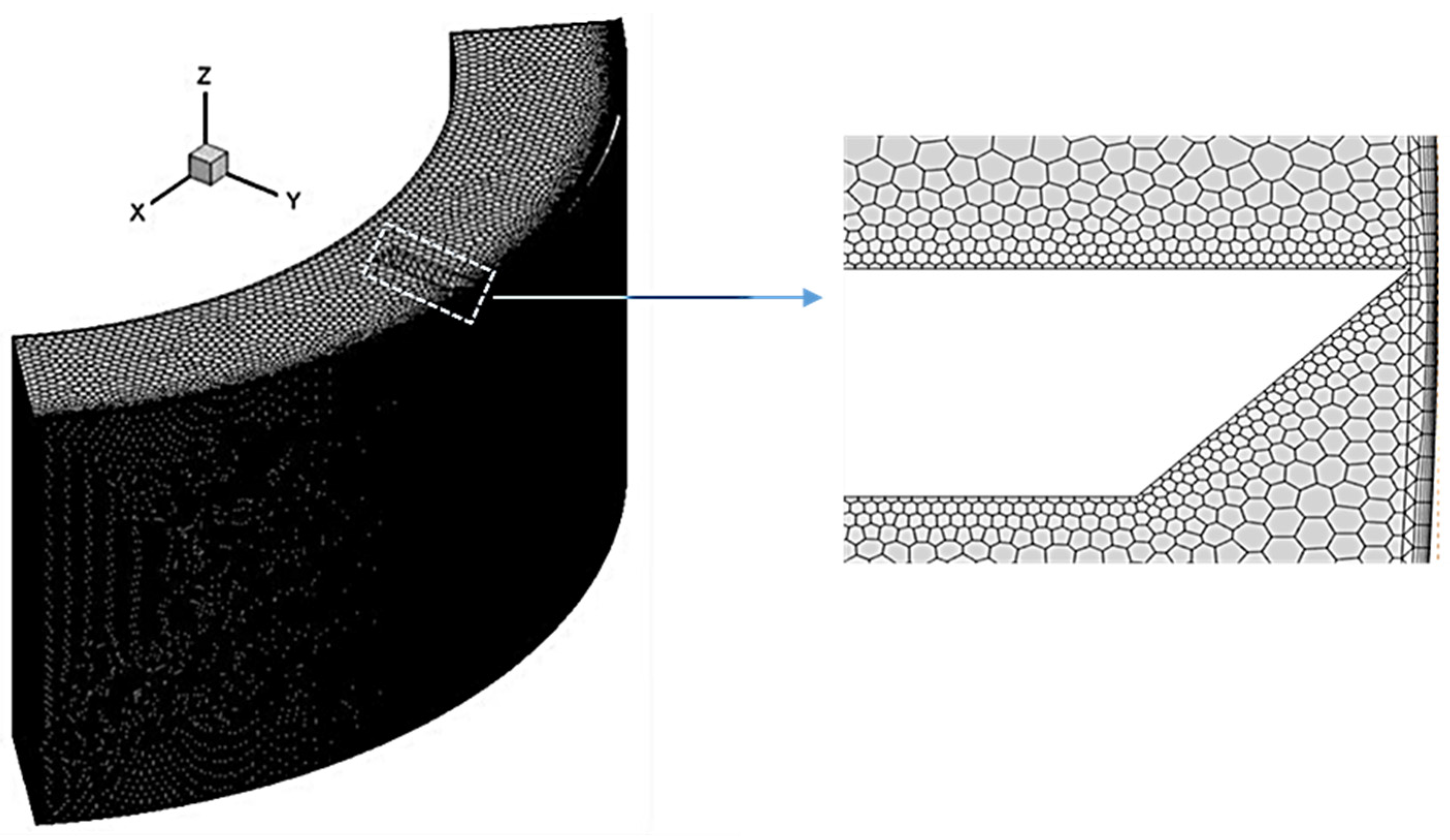
To ensure accurate resolution of the near-wall flow behavior—which directly governs the wall shear stress, liquid-film renewal, and secondary-flow generation that are central to the process-intensification analysis—a structured prism (inflation) layer mesh was applied on all solid wall surfaces in the computational domain. Specifically, prism layers were applied on: (i) the outer heating wall; (ii) the inner condenser surface; and (iii) the complete scraper surface, including the groove side walls, groove base faces, and sawtooth tip faces, so that the groove-induced near-wall shear field is resolved with consistent fidelity across all parametric cases. The prism layer configuration consists of six layers with a growth factor of 1.2 and a first-layer thickness of 0.15 mm, yielding a total prism layer thickness of approximately 1.37 mm. This configuration was designed to achieve an area-averaged y+ in the range of 30–100 on the heating wall and scraper surface under the baseline operating condition (120 r/min, μ = 0.222 Pa·s), which is consistent with the standard wall function treatment employed in the RNG k-ε turbulence model. The area-averaged y+ value on the heating wall obtained from the converged baseline simulation was 54.3, and that on the scraper wall surface was 47.8, both falling within the target range and confirming that the near-wall mesh resolution is compatible with the standard wall function approach. This prism layer strategy, combined with the local volumetric refinement around the scraper and groove features, provides a robust near-wall treatment that accurately captures the thin-film shear layer, wall-renewal behavior, and the associated torque and vorticity response reported in Section 3. The three-dimensional mesh structure is shown in Figure 2.
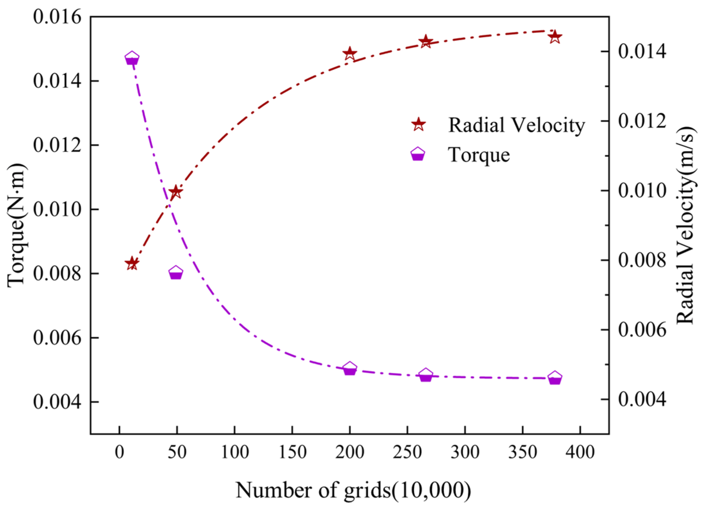
To ensure that the numerical results were independent of mesh density, a strict mesh-independence study was carried out using five mesh schemes with different cell numbers (0.10, 0.50, 2.00, 2.66, and 3.78 million cells). Two complementary indicators were monitored after convergence: (i) the average torque on the scraper wall, adopted as the primary global indicator, and (ii) the area-weighted average radial velocity on the mid-height cross-sectional plane ( z = 60 mm), adopted as a supplementary local flow indicator. Torque was selected as the primary criterion because it is a global integral mechanical quantity obtained from the combined contributions of viscous shear stress and pressure force over the entire scraper wall. It therefore reflects the overall momentum-exchange behavior of the whole flow domain, including the liquid pool region, the near-wall thin-film region, and the bulk rotating flow, rather than the flow state at a single location. Such a global quantity is particularly suitable for mesh-sensitivity assessment in rotating flow systems, where local variables may appear stable before the overall solution has fully converged. To complement this global indicator, the area-weighted average radial velocity at z = 60 mm was additionally monitored, because radial secondary flow is the key hydrodynamic feature associated with the mixing enhancement targeted by the grooved scraper design.
As shown in Figure 3, both indicators exhibit consistent convergence trends across the five mesh schemes. The two coarsest meshes (0.10 and 0.50 million cells) are included to illustrate the pre-convergence behavior, whereas the quantitative error assessment for mesh selection is focused on the refined-mesh interval from 2.00 million cells onward. When the mesh number was increased from 2.00 to 2.66 million, the relative error in average torque decreased from 4.2% to 2.1%, and that in the area-weighted average radial velocity decreased from 3.8% to 1.9%. With further refinement to 3.78 million cells, only marginal changes were observed, with the relative errors decreasing slightly to 1.86% and 1.7%, respectively. These results indicate that the solution had essentially reached mesh-independent behavior at 2.66 million cells. Considering both computational accuracy and computational cost, the mesh with 2.66 million cells was therefore adopted for all subsequent three-dimensional simulations.
To quantitatively characterize the mixing intensification achieved by different scraper micro-geometries, four hydrodynamic indicators are formally defined and consistently applied throughout Section 3. The area-averaged vorticity magnitude (Ω, s−1) evaluated on the mid-height cross-sectional plane (z = 60 mm) quantifies the rotational intensity of the secondary flow vortices that drive pool–film exchange and directly oppose the mixing inhibition identified by Komori et al. The area-averaged wall shear stress ( τ w , Pa) on the heating wall quantifies the mechanical renewal intensity of the wall liquid film, governing the frequency of surface refreshing and the elimination of concentration gradients at the evaporation surface. The turbulent kinetic energy (k, m2s−2) quantifies the overall turbulence level and energy available for convective mixing across the liquid pool and film region. The area-averaged radial velocity ( V r , m/s) evaluated at five axial planes (z = 10, 30, 60, 90, 130 mm) directly quantifies the radial momentum transport responsible for liquid exchange between the pool and the wall film. These four indicators collectively provide a multi-dimensional and physically grounded evaluation framework that connects scraper micro-geometry to hydrodynamic process intensification in the WFMD.

2.4. Model Validation

In addition to mesh independence verification, the model validation in this study was strengthened by introducing a three-level quantitative validation framework based on hydrodynamic equivalence between the present wiped-film molecular distiller (WFMD) and scraped-surface heat exchangers (SSHEs), for which established benchmark data are available in the literature [14,15,16]. As summarized in Table 3, the validation includes: (i) near-wall shear field (local metric), (ii) average liquid-film thickness scale represented here by an equivalent hydrodynamic film-layer thickness (mesoscale metric), and (iii) scraper torque (global mechanical-energy-transfer metric). For the baseline case (inline scraper, 120 r/min), the area-weighted wetted-wall shear metric gives Φ = S ˉ w / N = 1134.91 , which lies within the established SSHE scraped-surface benchmark range ( S / N 1000 3000 ), indicating a quantitatively reasonable prediction of the near-wall shear intensity relevant to film renewal and mixing intensification. Using the shear-gap relation under the same baseline condition, the equivalent hydrodynamic film-layer thickness is δ eq = 1.278   mm , compared with the benchmark-equivalent value δ eq = 1.257   mm , giving a relative deviation of 1.70%. The CFD-predicted scraper torque ( 0.0205   N m ) was further compared with the torque estimated from the McKenna correlation [25] ( 0.0237   N m ), with a relative deviation of 13.3%, demonstrating reasonable prediction of the global mechanical energy transfer from the scraper to the fluid. Table 3 provides the primary basis for confidence in the subsequent comparative parametric analysis.
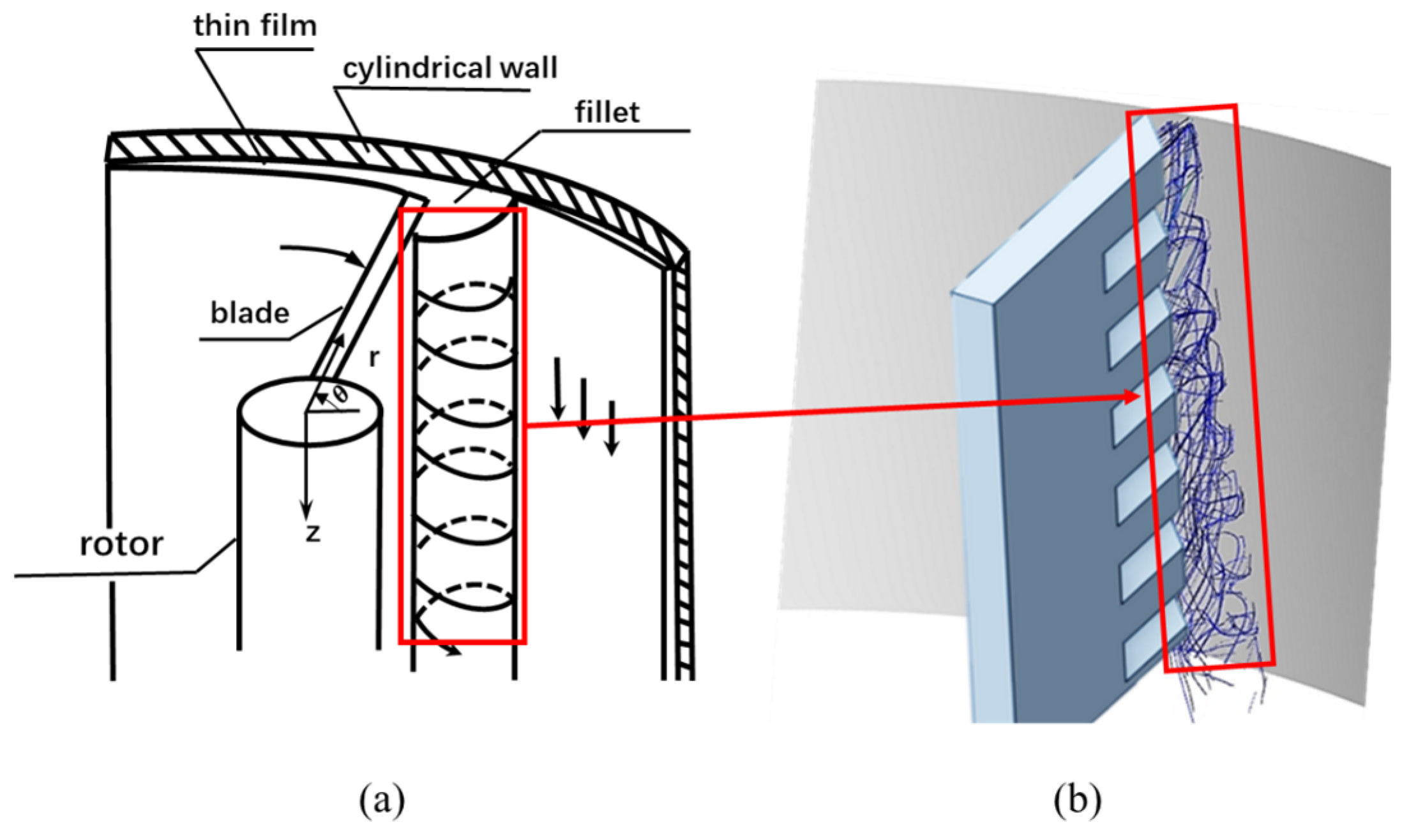
In addition to the quantitative comparisons above, the trajectory-based comparison with Komori’s theoretical schematic was retained as a complementary qualitative consistency check of the canonical wiped-film flow topology. Because Komori’s geometry differs from the present WFMD configuration, the comparison is used only as a qualitative morphology-level consistency check rather than a one-to-one validation of identical streamlines. For wiped-film molecular distillers, two iconic hydrodynamic features are expected: (1) the head wave generated at the leading edge of the scraper with local vortex mixing, and (2) spiral downward transport of the liquid film along the wall under the combined action of gravity and scraper rotation.
When the scraper moves, a head wave is generated at its front end, and the head wave flows spirally along the axial direction under the action of the scraper and gravity. When the scraper renews the fluid of the head wave, the fluid in the upper head wave flows axially to the renewed position of the lower layer, and this cycle continues, making the liquid phase flow spirally downward along the wall under the action of the scraper. Figure 4a provides a schematic depiction of the canonical flow topology reported by Komori, and Figure 4b shows the corresponding liquid-phase trajectories extracted from the present simulation in the near-scraper region. As shown in Figure 4, the simulated liquid trajectories reproduce the expected spiral transport and head-wave recirculation of wiped-film flow, thereby supporting the physical plausibility of the predicted hydrodynamic regime.
From the overall flow trajectories, it can be clearly seen that the liquid phase particles released from the inlet exhibit regular spiral downward movement trajectories under the combined action of gravity and the scraper. The fluid close to the outer wall forms a stable spiral flow, and the flow pattern is highly consistent with the theoretical expectation. The locally enlarged view near the scraper further reveals the complex details of the flow field. The trajectories colored according to the liquid volume fraction show that the blue trajectories, as the fluid close to the wall, have the most regular flow path, forming a stable spiral liquid film. In the leading edge region of the scraper, the flow is more complex. The trajectories show intense vortex formation, entrainment and mixing phenomena, and part of the gas is drawn into the liquid phase, forming a gas-liquid mixing zone. This reflects the intense fluid disturbance caused by scraper action [35] and provides an intuitive indication of strong mixing inside the liquid pool in front of the scraper.
Together with the quantitative validation results in Table 3, the qualitative agreement in Figure 4 supports the subsequent comparative parametric analysis.
To connect the hydraulic indicators to practical constraints of wiped film molecular distillation, the present evaluation accounts for film continuity, residence time, and mechanical power demand. The distillation process requires a continuous and stable wall film to preserve effective transfer area and prevent dry wall formation, and it requires sufficient residence time on the heated wall for transfer-related processes while maintaining gentle thermal exposure for heat-sensitive feeds. In the hydraulic analysis, these requirements are reflected by avoiding overly high axial transport rates, avoiding excessively thin and strongly nonuniform films that may rupture, and avoiding excessive torque that would increase power consumption and mechanical loading. The recommended designs are therefore those that enhance secondary flow mixing and wall renewal while satisfying these constraints under the baseline operating condition.
It should be noted that mixing time—a standard and widely used metric for mixing characterization in batch stirred-tank and closed-vessel systems [36]—is not directly applicable in the present continuous rotating-film context. In a WFMD, mixing performance is governed by the steady-state spatial distribution and intensity of secondary flow rather than by the temporal homogenization of a tracer, and the present simulations do not solve a scalar transport equation. The four indicators defined above are therefore the physically appropriate proxies for mixing intensification in this system. Tracer-based scalar transport simulations to enable mixing time and residence time distribution quantification in the WFMD are identified as a valuable direction for future work.
Based on the above numerical setup, evaluation system, and practical constraints, the present study should be understood as a screening-based parametric comparison of two scraper micro-geometric variables—groove width (W) and tip included angle ( θ )—tested at discrete levels under the same baseline operating condition. Accordingly, the terms “recommended” and “best-performing” used in Section 3 and the Conclusions denote the top-performing configuration within the investigated discrete set, rather than a global optimum obtained from a formal uncertainty-aware optimization framework. The robustness of this screening-based recommendation is judged within the investigated design space by multi-indicator agreement, including vorticity gain, wall shear stress gain, and torque-related response.

3. Results and Discussion

In the present study, the rotational speed was fixed at 120.0 r/min so that the hydrodynamic effects of groove width and scraper tip angle could be isolated under a representative baseline operating condition. Therefore, the current results do not constitute a quantitative parametric evaluation of rotational-speed effects. From a hydrodynamic perspective, increasing the rotational speed is expected to strengthen wall shear, liquid-film renewal, and secondary-flow generation, which are generally favorable for pool–film exchange and mass-transfer-related performance. However, excessive rotational speed may also increase axial transport and torque while shortening the effective residence time on the heated wall. Conversely, a lower rotational speed would weaken radial mixing and wall renewal, although it may increase residence time. Thus, the overall effect of rotational speed is expected to reflect a trade-off between mixing enhancement, residence-time preservation, and mechanical power demand.
Unless otherwise stated, the results reported in Section 3 correspond to the representative ethylene glycol/glycerol case-study composition (42.0 mol% ethylene glycol) under the baseline operating condition at an absolute chamber pressure of 15.0 Pa. Accordingly, the absolute values of the hydrodynamic indicators reported below should not be generalized directly to other feed compositions without re-specifying the thermophysical properties, because composition changes may alter viscosity, density, viscous damping, and the resulting flow-renewal behavior.

3.1. Influence of Groove Structure on Basic Characteristics of Flow Field

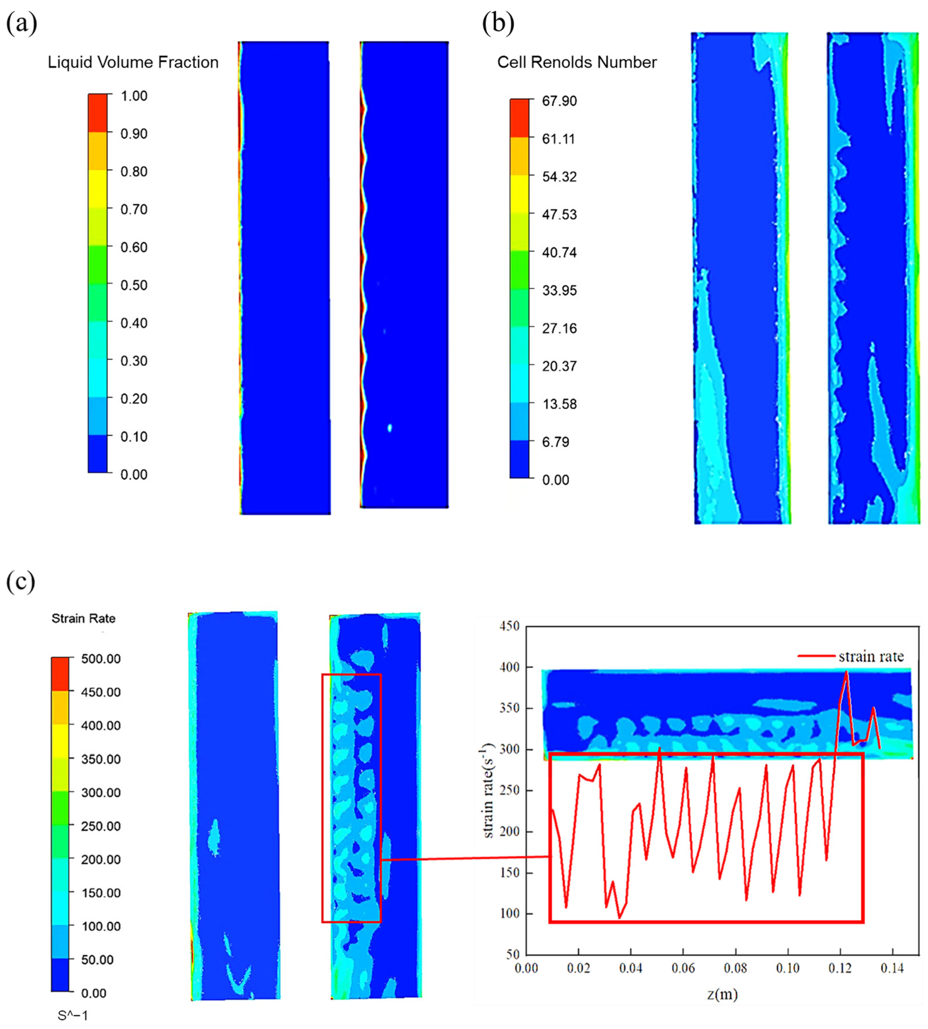
For this ethylene glycol and glycerol case study, the effectiveness of wiped-film molecular distillation is closely tied to hydrodynamic film renewal and near-wall disturbance under vacuum operation; therefore, the following analysis emphasizes flow-field indicators that govern interfacial refreshing and mixing in the high-viscosity liquid film. To intuitively demonstrate the fundamental influence of the groove structure on the liquid film morphology, the same axial plane was selected for comparative analysis of the inline scraper and the grooved scraper cases. Figure 5 compares the effects of the inline scraper and the grooved scraper from three dimensions. Figure 5a–c jointly link film morphology, local inertial–viscous balance, and near-wall shear disturbance, providing direct evidence that groove micro-geometry promotes interface renewal and liquid pool–film exchange. Figure 5a shows the liquid volume fraction distribution under the action of different scrapers. In the left figure, the liquid film presents an axially uniform two-dimensional planar shape, with a constant thickness along the axial direction. Although this uniform distribution ensures the continuity of the liquid film, it limits the effective area of the gas-liquid interface and makes it difficult to generate radial hydrodynamic exchange inside the liquid film. In contrast, the grooved scraper in the right figure has significantly changed the liquid film morphology. This periodic fluctuation increases the effective interfacial area and renewal frequency from a hydrodynamic perspective, suggesting improved hydrodynamically favorable conditions under vacuum operation; however, direct evaporation kinetics are not explicitly solved in the present model. At the same time, the periodic change in liquid film thickness generates a pressure gradient between the thin and thick regions, driving the continuous redistribution of the liquid, enhancing surface renewal, and effectively suppressing the formation of dry zones.
Figure 5b reveals the significant change of the grooved scraper on the flow field through the unit Reynolds number contour map. The unit Reynolds number characterizes the ratio of inertial force to viscous force of local flow, and is an important indicator for evaluating the flow state and mixing intensity. In Figure 5b, the unit Reynolds number is plotted over a range from 0.00 to 67.90, and the grooved scraper produces an evident periodic high intensity pattern near the wall compared with the smoother low intensity distribution in the inline case. From the figure, it can be observed by comparison that the unit Reynolds number near the wall of the grooved scraper presents an obvious periodic fluctuation distribution. The grooved scraper not only changes the flow characteristics of the wall liquid film but also has a significant impact on the liquid pool area in front of the scraper, indicating that the groove structure has successfully transmitted turbulent disturbances to the inside of the liquid pool, breaking the stratified state between the liquid pool and the liquid film in the traditional design.
The shear and strain rate distribution in Figure 5c reveals the mechanical essence of the above-mentioned differences in liquid film morphology. In Figure 5c, the strain rate magnitude is plotted over a range from 0 to 500 s−1, and the extracted axial profile shows repeated oscillations approximately from 100 to 450 s−1 along z, which quantitatively reflects the alternating shear enhancement associated with the tip and groove segments. The inline scraper generates a continuous and uniform shear stress band on the wall, while the grooved scraper forms a highly non-uniform periodic shear stress distribution on the wall. The red curve in Figure 5c clearly shows the fluctuation characteristics of the wall shear stress along the axial direction. The peak value of high shear stress accurately corresponds to the tip part of the scraper, where the gap between the scraper and the wall is the smallest, and the fluid is subjected to strong shear action; while the low shear stress region corresponds to the groove part, where the gap increases and the shear effect weakens. This periodic shear stress gradient along the axial direction is the primary hydrodynamic advantage of the groove design. It is worth noting that in the shear stress distribution of Figure 5c, the shear stress gradient disappears at both ends of the wall. This phenomenon stems from the end effect: at the axial boundary of both ends of the scraper, the fluid can flow freely in the axial direction without being constrained by the scraper, lacking the continuous shear action of adjacent scraper units. Therefore, the flow behavior in this region is closer to free surface flow, and the shear stress cannot be effectively established, leading to a gentle gradient. The non-uniform force field distribution drives the fluid near the wall to generate secondary flow, that is, eddies perpendicular to the main flow direction are generated outside the main scraping flow direction.
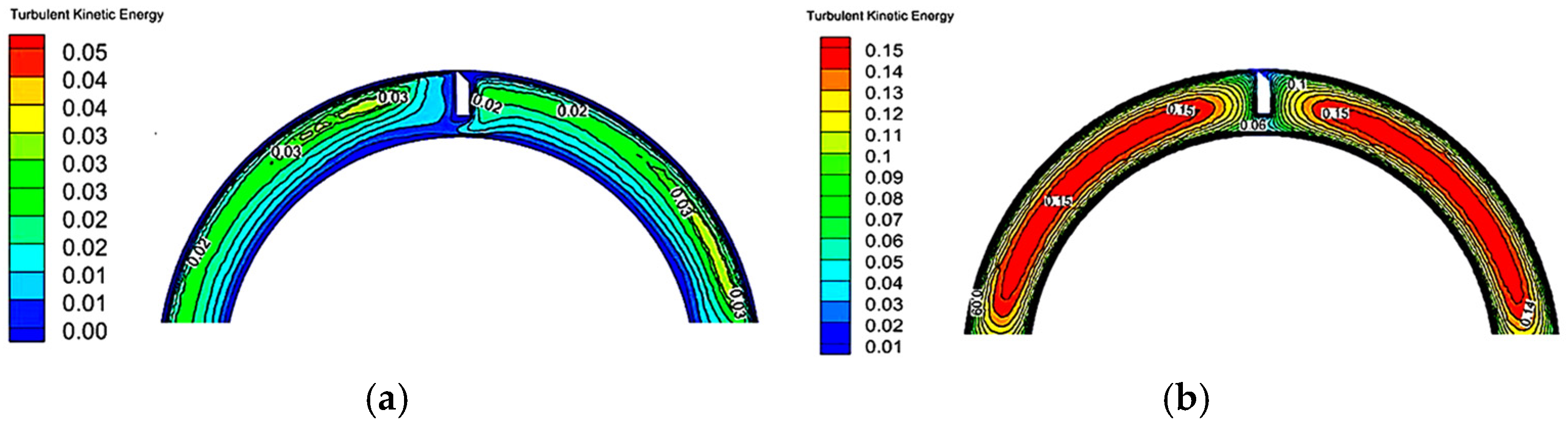
Figure 6 reveals how groove-induced disturbance spreads from the near-wall shear layer into the liquid pool region through the turbulent kinetic energy distribution. For the inline scraper case shown in Figure 6a, the turbulent kinetic energy ranges from 0.005 to 0.016 m2s−2 in the displayed cross-section, with the maximum located in the near-wall shear layer adjacent to the scraper and the minimum located in the bulk flow away from the wall. For the grooved scraper case shown in Figure 6b, the turbulent kinetic energy ranges from 0.06 to 0.25 m2s−2 in the displayed cross-section, with the maximum concentrated near the scraper leading region and the near-wall shear layer associated with local vortical structures, and the lower values occurring in the core flow region. The peak k therefore increases from 0.016 to 0.25 m2s−2, which corresponds to an amplification by about 16 times, indicating a substantially stronger turbulence level and flow disturbance induced by the grooved micro-geometry. Figure 6a shows that the turbulent kinetic energy contour lines generated by the inline scraper near the wall present a regular parallel distribution pattern, with uniform spacing and dense attachment to the wall, indicating that turbulent disturbances are mainly concentrated in the narrow shear layer formed between the scraper and the wall. From the density of the contour lines, it can be seen that the turbulent kinetic energy gradient decays rapidly in the radial direction, and the transmission capacity to the center of the flow field is limited. This distribution characteristic indicates that although the inline scraper can generate shear turbulence locally, it lacks an effective mechanism to diffuse the turbulent kinetic energy to a larger spatial range. In contrast, the turbulent kinetic energy distribution of the grooved scraper shown in Figure 6b exhibits significant inhomogeneity and spatial extensibility. Here, inhomogeneity means that the turbulent kinetic energy field is spatially non-uniform and forms alternating high and low intensity zones, rather than a nearly uniform near-wall band. Spatial extensibility means that the elevated turbulent kinetic energy region spreads away from the wall and along the axial direction, penetrating into the liquid pool region and interacting with the wake of adjacent scraper units. The most prominent feature is the formation of a turbulent kinetic energy distribution area extending both radially and axially behind the scraper, with the contour lines presenting an irregular vortex shape. Behind the scraper tip, the contour lines are dense and form a closed annular structure, indicating the presence of a strong turbulent core there; while at the position corresponding to the groove, the contour lines spread outward and interact with the turbulent regions of adjacent scrapers. From the perspective of the overall flow field, the turbulent kinetic energy contour lines are no longer limited to the vicinity of the wall but penetrate into the interior of the liquid pool region, forming a turbulent network throughout the near-wall flow field. The grooved scraper transforms the spatial distribution of turbulent kinetic energy from linear high-intensity concentration to planar medium-intensity diffusion. This distribution mode is more conducive to realizing hydrodynamic exchange between the liquid pool and the liquid film, responding to the core requirements in the design of wiped-film evaporators, which are to ensure uniform distribution, intense mixing, and flipping of the liquid film to eliminate concentration gradients [37].

3.2. Influence of Groove Width and Identification of a Recommended Value

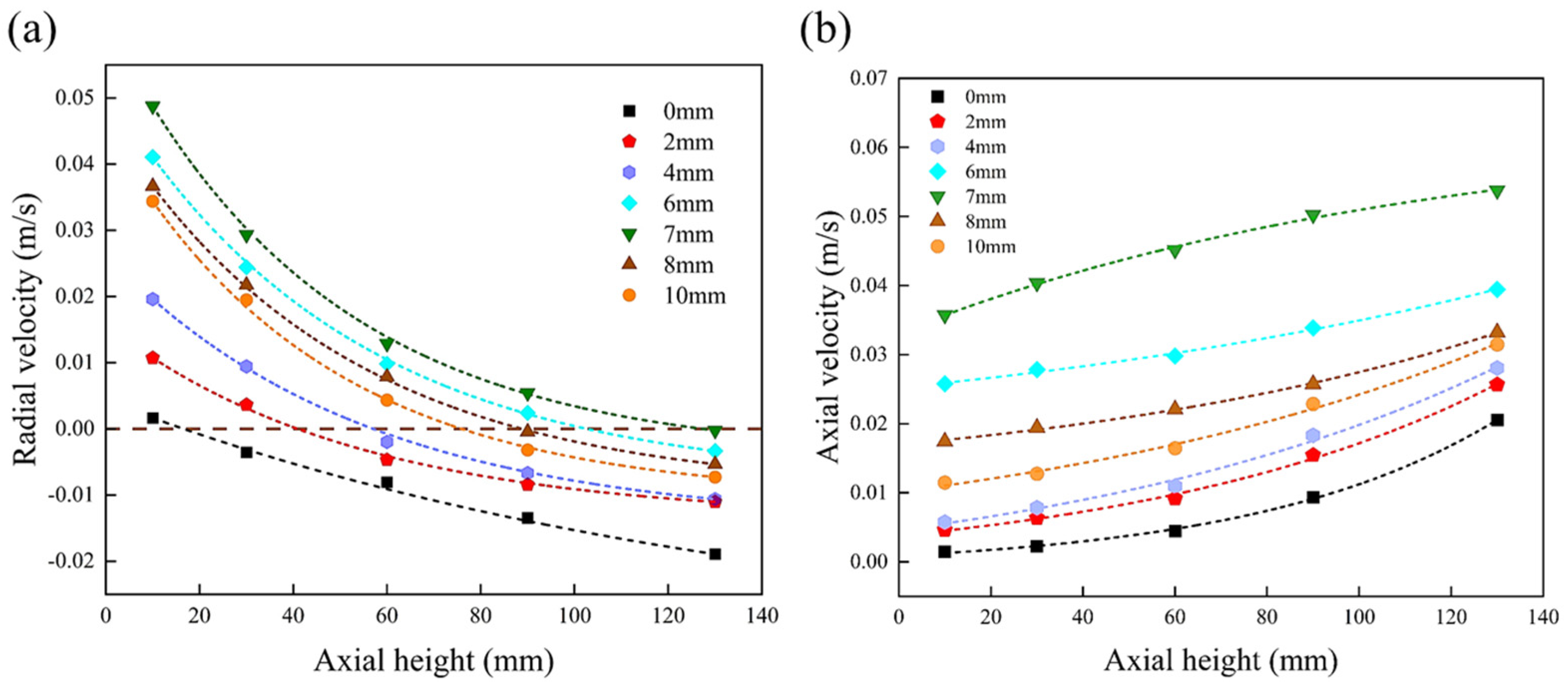
To quantitatively evaluate the influence of different groove widths from the perspective of macro flow, the average radial velocity and average axial velocity were extracted at five planes with axial heights of 10.0 mm, 30.0 mm, 60.0 mm, 90.0 mm, and 130.0 mm, as shown in Figure 7. Figure 7 shows the trade-off between radial mixing and axial transport. Figure 7a reflects the intensity of radial mixing, where negative values indicate the tendency of fluid backflow toward the center of the wall. The results show that all grooved scrapers generate stronger radial backflow than the inline scraper without grooves. Notably, the radial backflow velocity does not change monotonically with the groove width but reaches a maximum near the medium width. Figure 7b reflects the main transport rate of materials through the evaporator. As the groove width increases, the axial velocity increases accordingly, mainly because wider grooves reduce flow resistance. However, excessively high axial velocity means shortened residence time, which may be unfavorable for processes requiring longer residence time. In the present distillation context, residence time on the heated wall is treated as a process constraint, so groove widths that increase axial transport excessively are not preferred even if local disturbance is enhanced. This conclusion has been experimentally verified in Jasch’s [21] research on residence time. Overall, a groove width of 7 mm provides the strongest radial mixing while maintaining a moderate axial transport rate, indicating a favorable trade-off between radial mixing and axial transport rate among the tested cases.
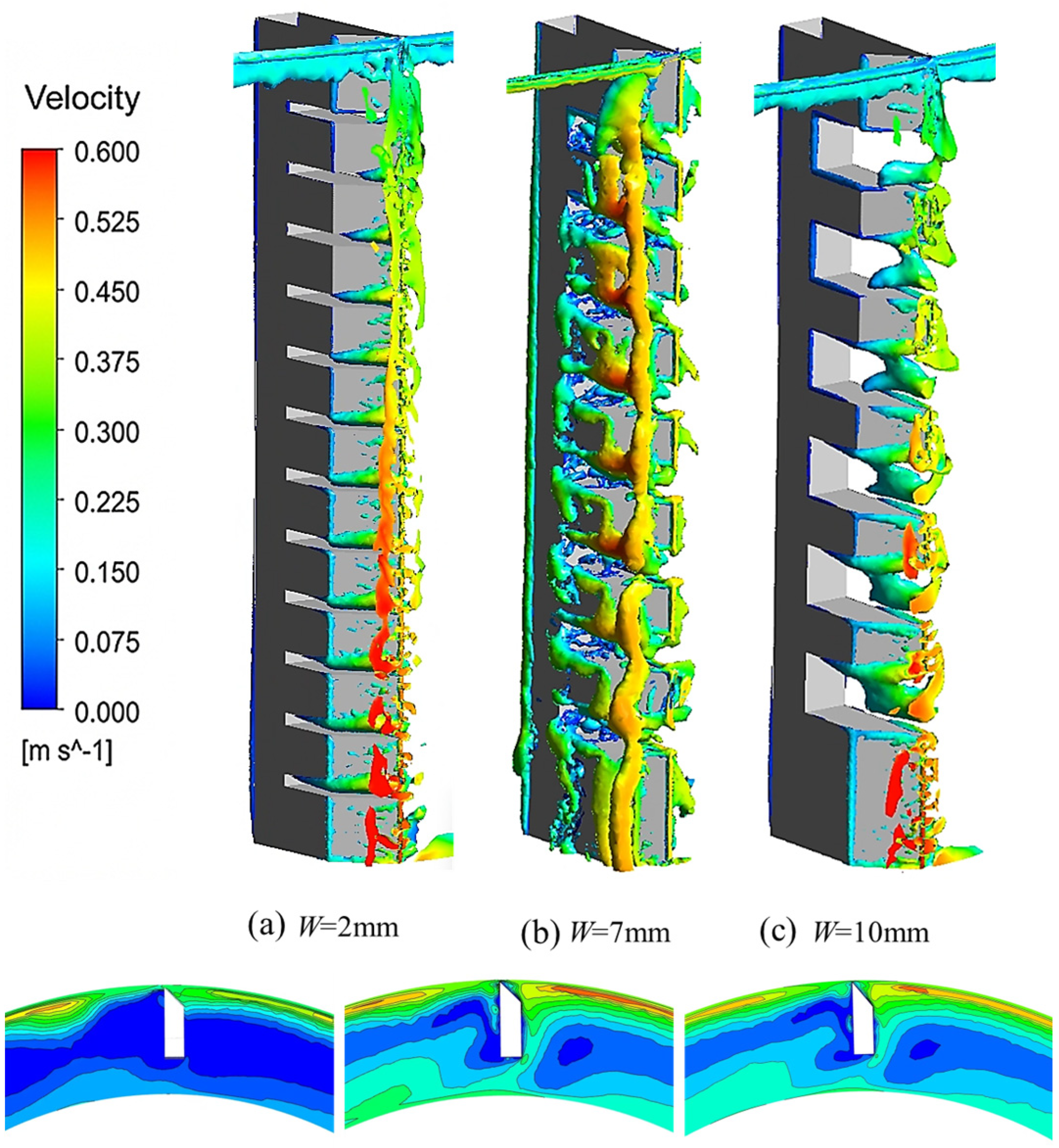
To deeply reveal the regulatory mechanism of groove width on the three-dimensional turbulent topological structure, Figure 8 presents both the Q-criterion vortex-core structures and the corresponding velocity magnitude contour maps on the mid-height cross-sectional plane (z = 60 mm) for three representative groove widths. The velocity contour panels (lower row) provide direct quantitative evidence of the spatial velocity distribution associated with each vortex topology, complementing the three-dimensional structural information provided by the Q-criterion iso-surfaces (upper row), and explain the non-monotonic change in radial mixing intensity observed in Figure 7. The longitudinal comparative perspective clearly reveals the filling morphology and evolution law of vortices in the groove space. Comparing the three typical groove-width cases, the flow field structure exhibits significant constrained-filling-dispersed evolution characteristics: as shown in Figure 8a, under the narrow groove condition of 2.0 mm, the vortex core structure shows obvious geometric constraint features. Due to the narrow groove space, the vortices cannot fully expand in the radial depth and can only attach to the groove root, forming a thin and discontinuous distribution. This constrained vortex structure limits the entrainment range of the fluid, making it difficult to achieve efficient radial hydrodynamic exchange. When the width increases to 7.0 mm (Figure 8b), the flow field morphology undergoes a substantial transition. The vortex core structure becomes extremely full and strong, almost filling the entire groove cavity. The figure shows that the vortices not only increase significantly in scale but also exhibit strong interaction and connectivity in the axial direction. This efficiently filled and continuously connected vortex network acts as the skeleton for fluid mixing, significantly enhancing the turbulent pulsation and momentum transfer inside the flow field, indicating that the geometric scale of the scraper at W = 7.0 mm is well-matched to the characteristic scale of the secondary flow, thereby yielding the strongest mixing response among the tested cases. However, when the width further increases to 10.0 mm (Figure 8c), the integrity of the vortex core structure begins to degrade. Although the expandable space for the fluid increases, the vortices in the figure appear relatively sparse, and structural fragmentation and shedding occur in the region far from the wall. This is because the excessively wide groove weakens the geometric constraint effect of the wall, leading to the rapid instability and dissipation of large-scale coherent structures in the absence of boundary support, which cannot maintain long-distance axial transport.
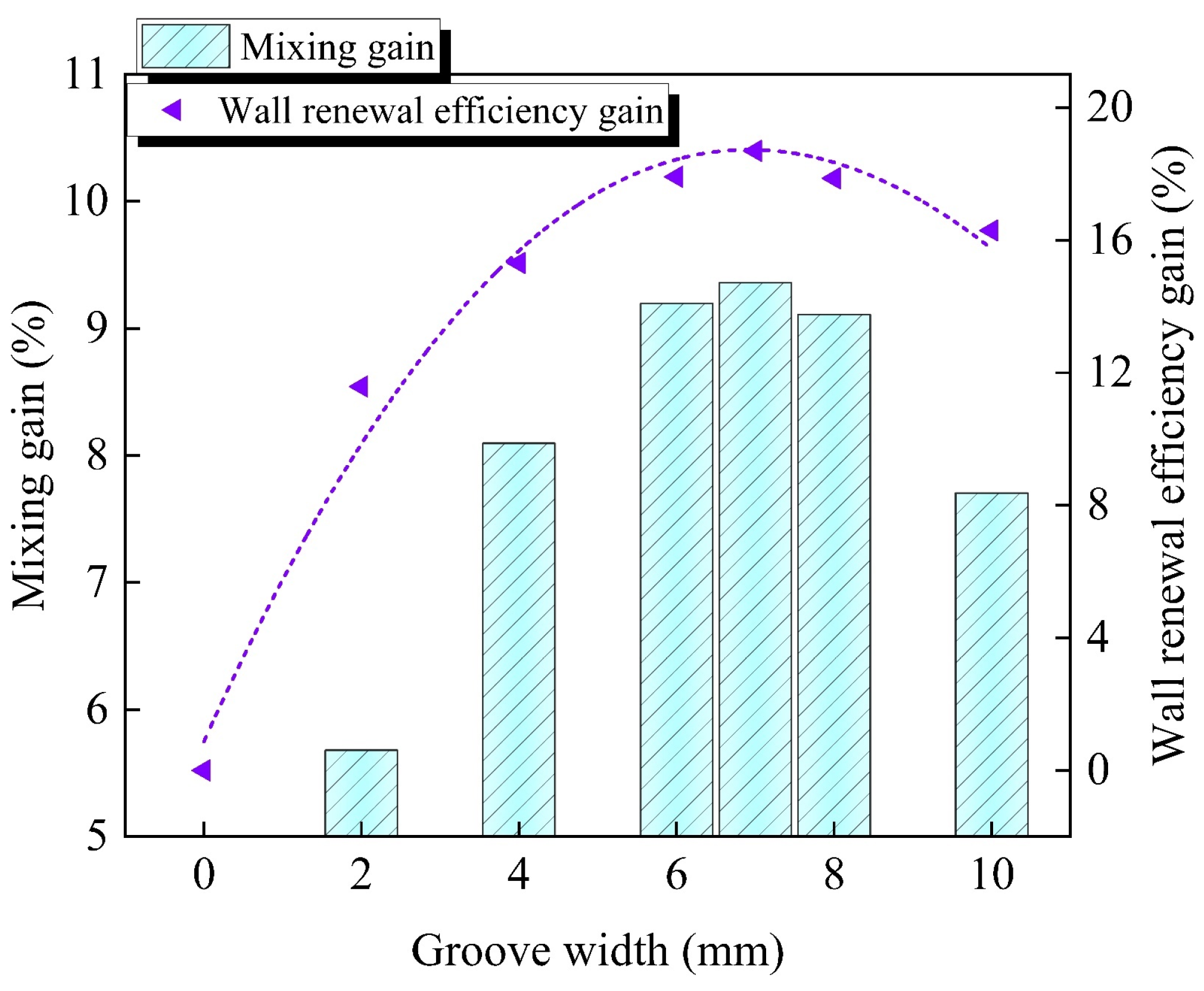
To accurately evaluate the comprehensive performance of different groove widths and recommend a design candidate based on screening comparisons, the inline scraper without grooves was used as the baseline. Figure 9 compares two core performance indicators relative to the inline scraper baseline (W = 0.0 mm). Here, “mixing intensity gain” refers to the percentage increase in area-averaged vorticity magnitude relative to the baseline, and “wall renewal frequency gain” refers to the percentage increase in area-averaged wall shear stress relative to the baseline. The bar chart presents the mixing intensity gain, and the dot-line chart presents the wall renewal frequency gain. Both show a significant trend of first increasing and then decreasing. The most critical finding is that the gain peaks of these two performance indicators, which characterize the internal mixing process and the wall renewal process, respectively, jointly point to a groove width of 7.0 mm. The mixing intensity gain is highly sensitive to groove width and reaches its peak at W = 7.0 mm, where the area-averaged vorticity magnitude is more than 9% higher than that of the inline scraper baseline. The wall renewal frequency gain likewise reaches its maximum at W = 7.0 mm, at nearly 20% above the inline scraper baseline. This indicates that there exists a most favorable width range to maximize the internal mixing driven by secondary flow. At the same time, the trend chart representing the wall renewal efficiency also shows a similar favorable trend. The gain of wall shear stress reaches the maximum value when the width is 7.0 mm, which is nearly 20% higher than that of the inline scraper. This proves that the recommended groove design can not only enhance the internal mixing of the fluid but also enhance wall renewal most strongly. The periodic enhancement of wall shear stress directly drives the continuous renewal of the liquid film, and this renewal process acts on both the velocity field and the concentration field. The coincidence of the peak points of these two core performance indicators strongly demonstrates that the groove width of 7.0 mm achieves synergistic enhancement in the two key links of internal mixing and wall renewal.
Although a formal robust optimization under uncertainty is not performed in this study, the recommendation of W = 7.0 mm is supported by multi-indicator agreement: the peaks of vorticity gain and wall shear stress gain coincide at W = 7.0 mm, and the torque-gain trend shows a consistent maximum at the same width. This consistency reduces reliance on any single metric and supports the robustness of the recommended groove width within the investigated design space.
Figure 10 illustrates how groove width influences torque and overall mechanical loading. The bar chart represents the torque value for each groove-width case, and the line chart reflects the growth rate change relative to the inline scraper (0 mm as the baseline). It can be observed from the bar chart that the total torque presents a non-monotonic trend of first increasing and then decreasing with the groove width. The line chart reveals a deeper energy conversion law: the relative growth rate reaches a peak of 6.6% at 7.0 mm, indicating that the total force exerted by the scraper on the fluid is the largest under this groove-width case. The physical essence of torque is a measure of the rotational mechanical energy transmitted from the scraper to the fluid. The groove width of 7.0 mm achieves a favorable balance between the torque value (0.0237 N·m) and the relative growth rate (6.6%). This balanced state ensures that the input mechanical energy can be maximally converted into effective turbulent kinetic energy that promotes mixing, rather than being dissipated in overcoming the overall flow resistance. The torque peak corresponds to the working condition where both vorticity and shear stress reach their peak values in the aforementioned analysis, verifying the rationality of 7.0 mm as the recommended groove width from the perspective of energy conservation.
To place these findings in the context of published scraper geometry modifications, it is noted that McKenna [25] reported mixing improvements through multi-section scraper designs aimed at disrupting the liquid pool, and Zhang et al. [26] demonstrated enhanced secondary flow through staggered rotor configurations in WFMDs. While direct numerical comparison is not straightforward due to differences in geometry, fluid properties, and evaluation metrics across studies, the vorticity gain of 9% and wall shear stress gain of 20% achieved by the grooved scraper at W = 7.0 mm represent quantitatively meaningful improvements over the inline scraper baseline under the present operating conditions, and are consistent with the level of hydrodynamic intensification reported for structured-surface modifications in analogous scraped-surface and rotating-film systems [32,33]. These results support the grooved micro-geometry as an effective process-intensification strategy within the investigated parameter space.

3.3. Effect of the Tip Included Angle: Balancing Wall Shear and Liquid Film Morphology

Based on the screening results for groove width, this section further investigates the influence of the scraper tip included angle (30.0°, 45.0°, 60.0°, 75.0°) on the flow field characteristics. The tip included angle is a key parameter in scraper design; it not only affects the hydrodynamic behavior but also directly determines the liquid film thickness and surface renewal rate, thereby profoundly influencing the overall hydrodynamic performance [38].
To deeply reveal the intrinsic influence of the scraper tip included angle on the mixing process, a quantitative analysis of the interaction between the scraper and the fluid from a mechanical perspective is required. As shown in Figure 11, the reaction force exerted by the fluid on the scraper can be decomposed into two characteristic components: the normal thrust perpendicular to the scraper surface (F1) and the tangential shear force parallel to the scraper surface (F2). Among them, F1 is mainly reflected in the pushing and blocking effect on the front liquid pool, directly affecting the geometric scale of the liquid pool; F2 is mainly responsible for exerting shear force on the wall liquid film, driving the spreading and surface renewal of the liquid film. Figure 11 provides the mechanical interpretation framework used to relate the included angle to liquid pool buildup, wall shear regulation, and subsequent vortex development.
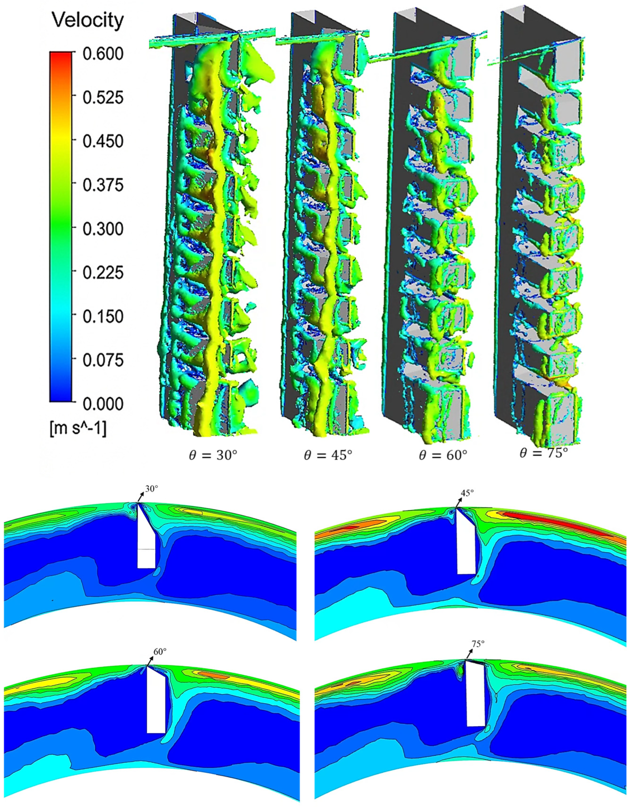
As the included angle θ increases from 30.0° to 75.0°, the competition and evolution of these two components dominate the changes in the flow field structure. Under the small included angle condition, the scraper surface is relatively flat, the normal thrust F1 is small, and the fluid experiences limited resistance, tending to pass quickly along the axial direction. This results in a large but loosely structured liquid pool in front; although the tangential component has a certain intensity, it is restricted by the thicker liquid layer and cannot effectively penetrate to the bottom to induce strong turbulence. When the included angle increases to 45.0°, the fluid force balance reaches a favorable state: the enhanced normal thrust F1 establishes a liquid pool area with moderate pressure in front, providing the necessary material basis for vortex development; at the same time, the synchronous increase in tangential shear force F2 ensures effective entrainment of the fluid inside the liquid pool. Their synergistic effect induces the most coherent and intense secondary flow vortices among the tested cases. When the included angle further increases to a large value, the scraper exerts a strong squeeze on the fluid. Although the tangential shear effect theoretically reaches its peak at this time, the geometric space of the liquid pool is severely compressed, so the shear energy is mainly consumed to overcome the enormous flow resistance, which instead leads to the fragmentation and instability of the coherent vortex structures. Therefore, exploring the favorable mechanical matching point between F1 and F2 is the key to achieving efficient mixing.
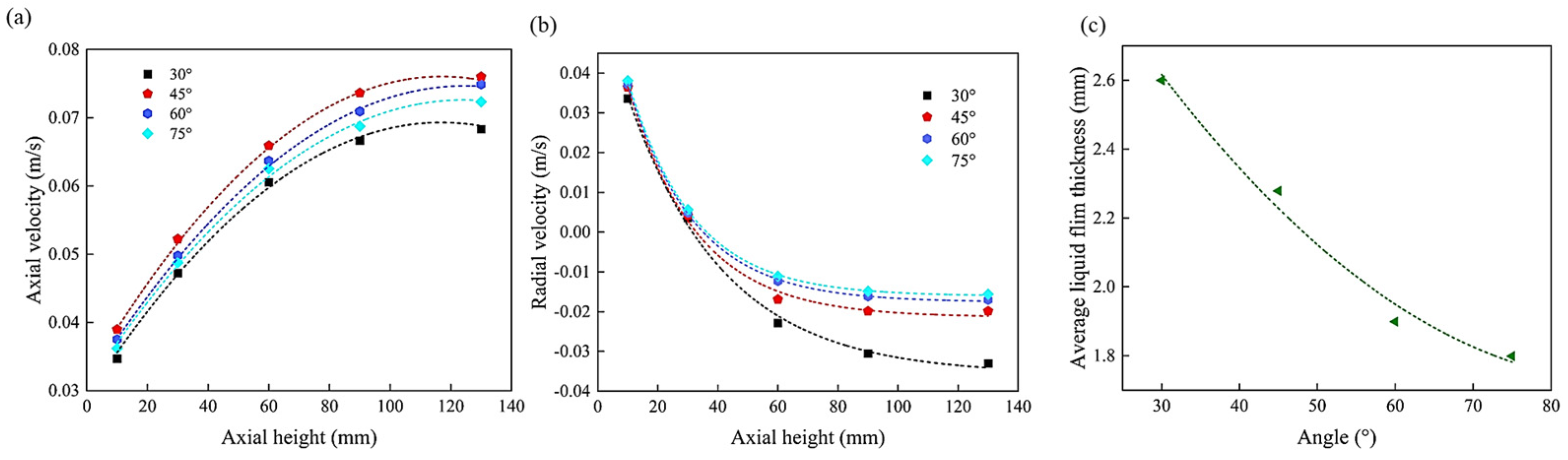
Under the selected groove width of 7.0 mm, the average values of radial velocity and axial velocity were extracted at five planes with axial heights of 10.0 mm, 30.0 mm, 60.0 mm, 90.0 mm, and 130.0 mm. As shown in Figure 12, the influence of the tip included angle on the overall velocity field is relatively mild; however, its regulatory effect on the flow near the wall is extremely significant. Figure 12 quantifies how the included angle changes axial transport, radial backflow, and film thickness, thereby underpinning the constraint-based angle recommendation, which is consistent with the conclusions reported by Hisashi [39], Yatagnene [16], and other researchers. The liquid film thickness decreases monotonically with the increase of the included angle, reaching a minimum of 1.79 mm at 75.0°, while being the thickest at 30.0° (2.6 mm). Behind this phenomenon lies the transformation of two dominant physical mechanisms. For small included angles, a large head wave forms in front of the scraper, creating a local high-pressure zone that squeezes a large amount of liquid below the scraper, resulting in a thicker liquid film. The existence of this high-pressure head wave also explains why the strongest radial backflow velocity is generated at a 30.0° included angle, as well as the decrease in axial velocity caused by the significant flow resistance. For large included angles, the effect shifts to being dominated by efficient shear action. Due to the small volume of the head wave and insignificant pressure accumulation, the scraper tip can effectively shear and spread the liquid on the wall, leaving an extremely thin liquid film; however, this liquid film is unevenly distributed and prone to rupture. In this work, film continuity and residence time are treated as practical constraints, so the recommended tip angle is selected by balancing film thinning with uniformity and sufficient contact time on the heated wall. Although thinning the liquid film can significantly reduce thermal resistance and improve the heat transfer coefficient on the evaporation side, an excessively thin liquid film will shorten the effective residence time of volatile components on the heating surface. If the residence time is insufficient to provide sufficient contact time for transfer-related processes, it may instead lead to a decrease in separation depth. The regulation of liquid film thickness is essentially a practical design trade-off, balancing the benefit of film thinning against the need to maintain sufficient residence time and film continuity for stable operation. Therefore, the 45.0° included angle, while reducing the average liquid film thickness, can better balance operational favorability and liquid film distribution uniformity.
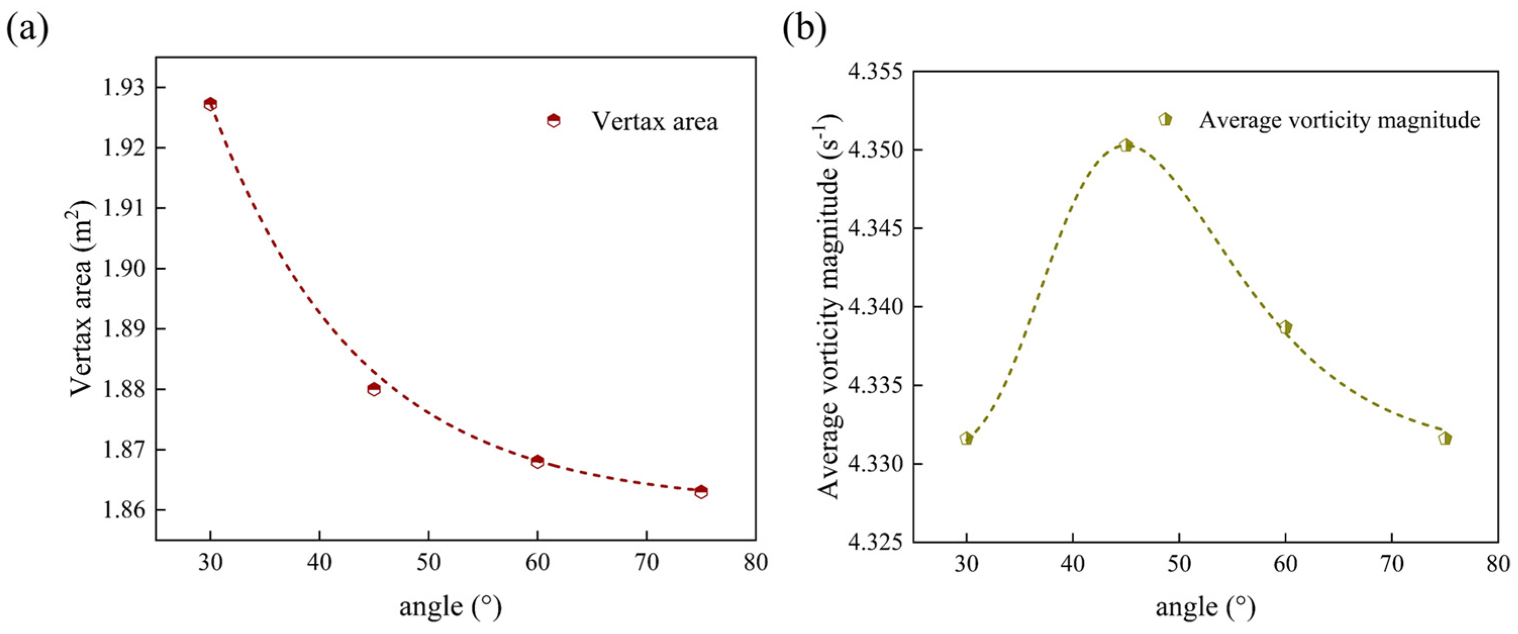
To quantitatively analyze the evolution mechanism of the flow field structure, Figure 13 extracts two key topological characteristics of the main vortex flow in front of the scraper under different included angles: effective vortex area and regional average vorticity. Figure 13 shows the angle dependence of vortex area and average vorticity. Figure 13a shows that the vortex area decreases monotonically with the increase of the included angle. Under the 30.0° condition, the weak normal boundary constraint allows the fluid to spread easily along the axial direction, forming a large-area but loosely structured backflow region with low vorticity. However, when the included angle increases to 75.0°, severe blockage occurs in front of the scraper, forcing the fluid to accumulate upward; although F2 reaches its peak at this time, the liquid pool space is compressed, and the shear energy is mainly used to overcome flow resistance, which instead leads to the fragmentation of the vortex structure. Therefore, the mechanical matching between F1 and F2 under the medium included angle is the key to achieving efficient mixing.
Unlike the monotonic change of area, Figure 13b reveals that the vortex mixing intensity exhibits a sensitive non-monotonic characteristic, with the average vorticity reaching its peak at 45.0°, verifying the inference that the synergistic effect of F1 and F2 is strongest at this angle. When the included angle increases to 45.0°, the growth of F1 and F2 achieves a balance: the moderate normal thrust forms a liquid pool area with an appropriate scale, providing the material basis for the vortex; the synchronously enhanced tangential shear force effectively entrains the fluid inside the liquid pool, and their synergy induces the strongest and most stable secondary flow vortex. At 30.0°, although the vortex covers a wide range, the fluid movement is stagnant, and most of the energy is dissipated in pushing the large liquid pool rather than driving internal turbulence, resulting in a low average vorticity. Conversely, at 75.0°, the fragmentation of the vortex prevents the effective conversion of flow field energy into stable rotational kinetic energy, leading to a decline in mixing intensity. Only under the 45.0° condition does the system maximize the conversion efficiency of shear energy to vortex kinetic energy while retaining an appropriate vortex scale, achieving the maximum of mixing intensity.
To further verify the vortex breakdown mechanism inferred from the quantitative vorticity analysis in Figure 13, Figure 14 presents a composite visualization for the four tip-angle cases. The upper row shows Q-criterion iso-surfaces (threshold Q = 0.015 s−2)—a vortex identification method based on the second invariant of the velocity gradient tensor—with velocity magnitude overlaid on the iso-surface to reveal the internal flow speed distribution within the identified vortex cores. The lower row shows velocity magnitude contour maps on the mid-height cross-sectional plane (z = 60 mm) as a quantitative two-dimensional reference of the overall flow field. The Q-criterion upper panels are thus inherently vortex-structure representations, and their three-dimensional perspective reveals details of vortex axial continuity, coherence, and breakdown that cannot be captured by the two-dimensional planar analysis in Figure 13 alone. Together, the two rows establish a direct connection between the three-dimensional vortex topology and the planar velocity distribution, providing complementary evidence for the vortex coherence trends discussed in this section. Comparing the four typical included-angle cases, the flow field exhibits a non-monotonic evolution law from loose accumulation to stable order and then to structural disintegration: as shown in Figure 14, under the small included angle of 30.0°, although the vortex core area is the largest, its structure is relatively loose and irregular, indicating that the fluid is mainly in a passively pushed state without a strong rotating core. When the included angle increases to 45.0°, the flow field structure reaches the most coherent state. A continuous, compact spiral vortex tube along the axial height is clearly visible in the figure. This strong, coherent structure proves that at this angle, the shear effect of the scraper successfully induces stable secondary flow, greatly enhancing fluid mixing. However, as the included angle further increases to 60.0°and 75.0°, the integrity of the vortex core structure is destroyed. Most notably, under the 75.0° condition, the originally continuous spiral vortex tube undergoes severe vortex breakdown. It clearly shows that the vortex core disintegrates into a large number of discrete, disordered small-scale fragments. This sudden change in topological structure confirms that in the high-intensity shear flow field induced by large included angles, the fluid cannot maintain large-scale coherent structures, leading to blocked conversion paths of kinetic energy to turbulent dissipation. Thus, it explains the sharp decline in mixing intensity from a microscale mechanism. This visual evidence conclusively confirms that in the high-intensity shear field formed by large included angles, the fluid cannot sustain large-scale ordered vortex structures, resulting in interrupted mixing channels—thereby explaining why mixing intensity decreases rapidly when the included angle exceeds 45.0°.
To verify the reliability of the numerical method from the perspective of macroscale fluid morphology and to reveal the regulatory mechanism of the scraper tip included angle on flow, Figure 15 presents zoomed contour maps of the liquid volume fraction focused on the scraper leading-edge region under four tip included angles, alongside the canonical Komori schematic as a qualitative reference. The simulated bow-wave shape and gas–liquid interface topology at each angle show a high degree of consistency with the expected wiped-film flow features described in the literature [28], confirming the physical plausibility of the present model in predicting complex rotating multiphase flow behavior. On this basis, the zoomed CFD panels in Figure 15 directly reveal the significant evolution of bow-wave scale, gas–liquid interface curvature, and near-tip liquid film morphology under different tip included angles. By magnifying the scraper leading-edge region—the zone where pool–film exchange and vortex entrainment originate—these panels provide clear visual evidence for the physical mechanisms inferred from the vorticity and vortex-area analysis in Figure 13, and are in direct correspondence with the three-dimensional vortex-core structures shown in Figure 14. In particular, the moderate and fully structured bow wave at θ = 45° (Figure 15b) provides the material basis for the coherent vortex entrainment that yields the highest mixing intensity at this angle.
Under the 30.0° condition, due to the small normal thrust F1, the blocking effect of the scraper on the fluid is weak. The liquid pool spreads freely downward under the combined action of gravity and centrifugal force, forming a wide, thick, and extensively distributed liquid phase region. Although this macroscale morphology provides a spatial basis for large-scale vortices, it lacks a sufficient normal pressure gradient to drive intense backflow mixing, resulting in loose vortex structures. In contrast, when the included angle increases to 75.0°, the shear effect dominates, and the liquid phase accumulation area in front is sharply compressed, becoming sharp and narrow in shape, indicating that the material is rapidly sheared through the gap and cannot accumulate effectively. Under the 45.0° condition, the liquid pool presents an ideal morphology with moderate size and full structure. This macroscale spatial distribution not only avoids the formation of excessively large dead zones but also ensures sufficient material for vortex entrainment, providing the favorable macroscale physical field environment for achieving efficient vortex mixing.


4. Conclusions

This work investigates hydrodynamic process intensification in wiped-film molecular distillers (WFMDs) handling high-viscosity, heat-sensitive mixtures, where liquid pooling and weak pool–film exchange limit effective wall renewal and mixing. Using three-dimensional VOF-based CFD simulations, two scraper micro-geometric variables—groove width (W) and tip included angle (θ)—were systematically screened, and the main conclusions are as follows:
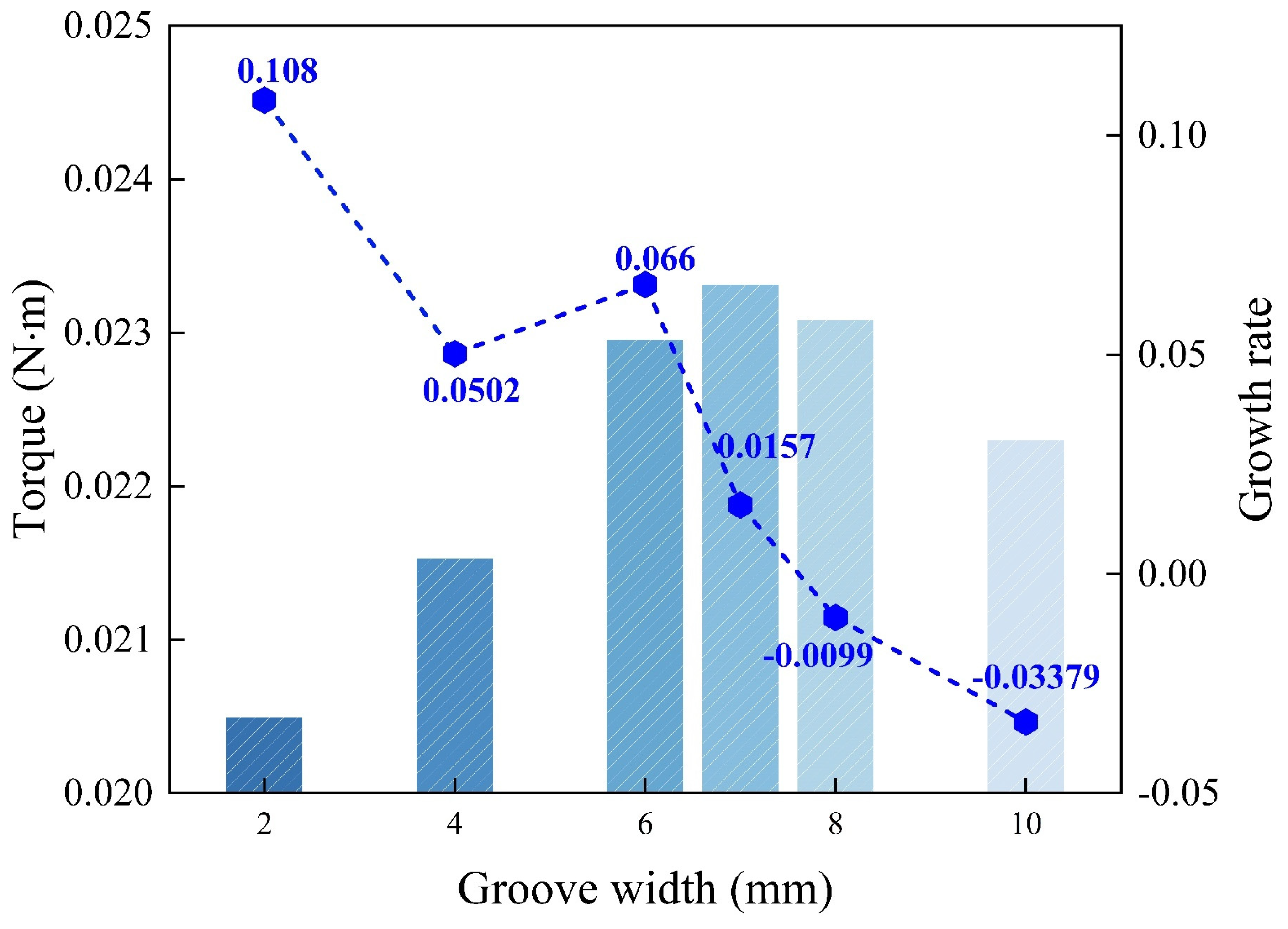
The grooved scraper design effectively converts rotational mechanical energy into stable secondary flow, thereby enhancing radial momentum transport, pool–film exchange, and turbulent mixing. Compared with the conventional inline scraper baseline, it amplifies peak turbulent kinetic energy by approximately 16-fold and generates a spatially extended turbulent network that penetrates into the liquid pool—both of which are favorable for hydrodynamic process intensification in WFMDs.
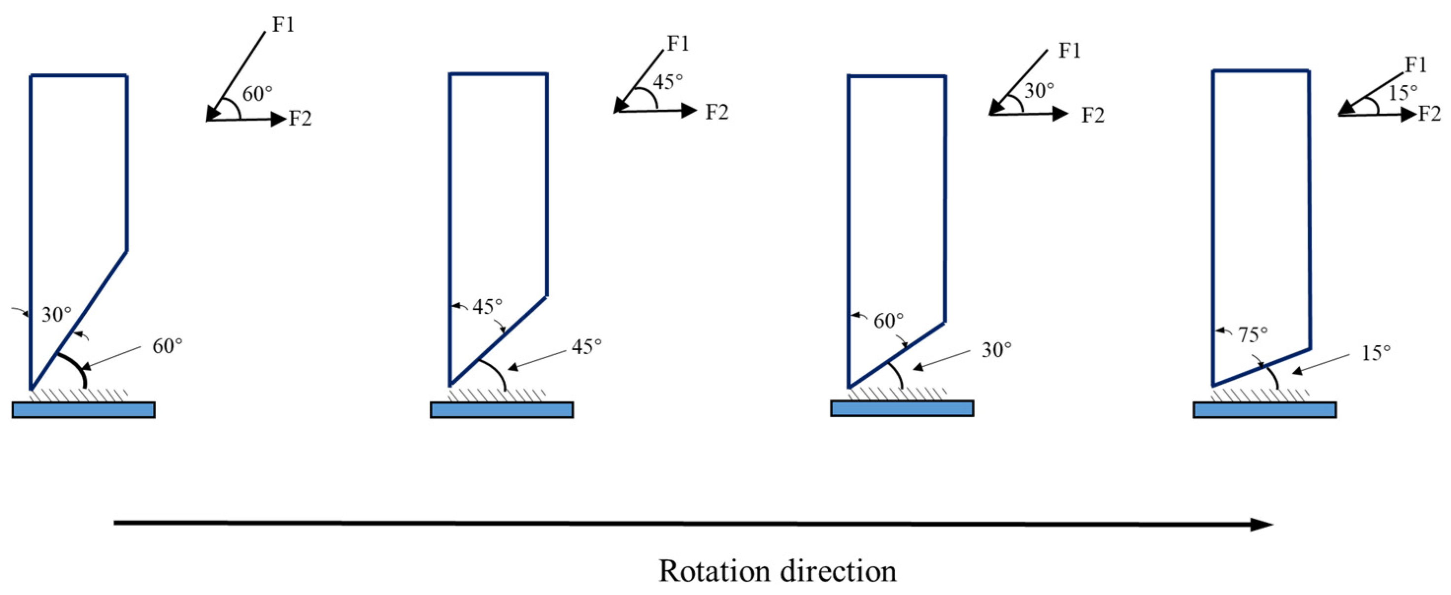
Within the investigated groove-width range (2.0–10.0 mm) under the baseline mixture composition and operating condition, W = 7.0 mm is identified as the best-performing candidate. This width achieves the highest vorticity gain (+9% relative to the inline baseline) and wall shear stress gain (+20%), while maintaining a moderate axial transport rate that preserves sufficient residence time. Excessively narrow grooves (e.g., W = 2.0 mm) confine secondary flow within the groove cavity, while excessively wide grooves (e.g., W = 10.0 mm) weaken vortex stability and shorten residence time.
Within the tested tip included angle range (30–75°) under the baseline mixture composition and operating condition, θ = 45° is identified as the best-performing configuration for hydrodynamic mixing and wall-film renewal. At this angle, the normal thrust (F1) and tangential shear force (F2) at the scraper tip achieve favorable mechanical matching, inducing the most coherent and intense secondary vortex structures (peak average vorticity), while maintaining a liquid film thickness (approximately 2.1 mm) that balances film thinning with sufficient residence time and film continuity.
Limitations: The present study is subject to several limitations, including its hydrodynamics-focused scope (without coupled energy and mass-transfer modeling), the constant-viscosity assumption at 20 °C, the composition-specific case setting (42.0 mol% ethylene glycol/glycerol), the fixed rotational speed (120 r/min), and the screening-based rather than formal optimization framework.
Future Work: Subsequent studies should incorporate temperature-dependent viscosity and composition-dependent thermophysical properties, extend the parametric study to multiple rotational speeds, include coupled heat and mass transfer modeling to directly evaluate separation performance, and perform experimental validation of the hydrodynamic intensification mechanisms identified in this work.

Author Contributions

Conceptualization, Y.S.; methodology, S.L., X.W. and X.Y.; formal analysis, D.W.; investigation, D.W.; Resources, Y.S.; data curation, S.L.; validation, K.W.; writing—original draft preparation, S.L.; writing—review and editing, S.L., D.W. and Y.S.; funding acquisition, Y.S. All authors have read and agreed to the published version of the manuscript.

Funding

This work was supported by the Department of Science and Technology of Shaanxi Province.: the Key Research and Development Program of Shaanxi Province (Grant No. 2023-YBSF-396).

Data Availability Statement

The original contributions presented in this study are included in the article. Further inquiries can be directed to the corresponding author.

Conflicts of Interest

The authors declare no conflicts of interest.

References

  1. Zeboudj, S.; Belhaneche-Bensemra, N.; Belabbes, R.; Bourseau, P. Modelling of Flow in a Wiped Film Evaporator. Chem. Eng. Sci. 2006, 61, 1293–1299. [Google Scholar] [CrossRef]
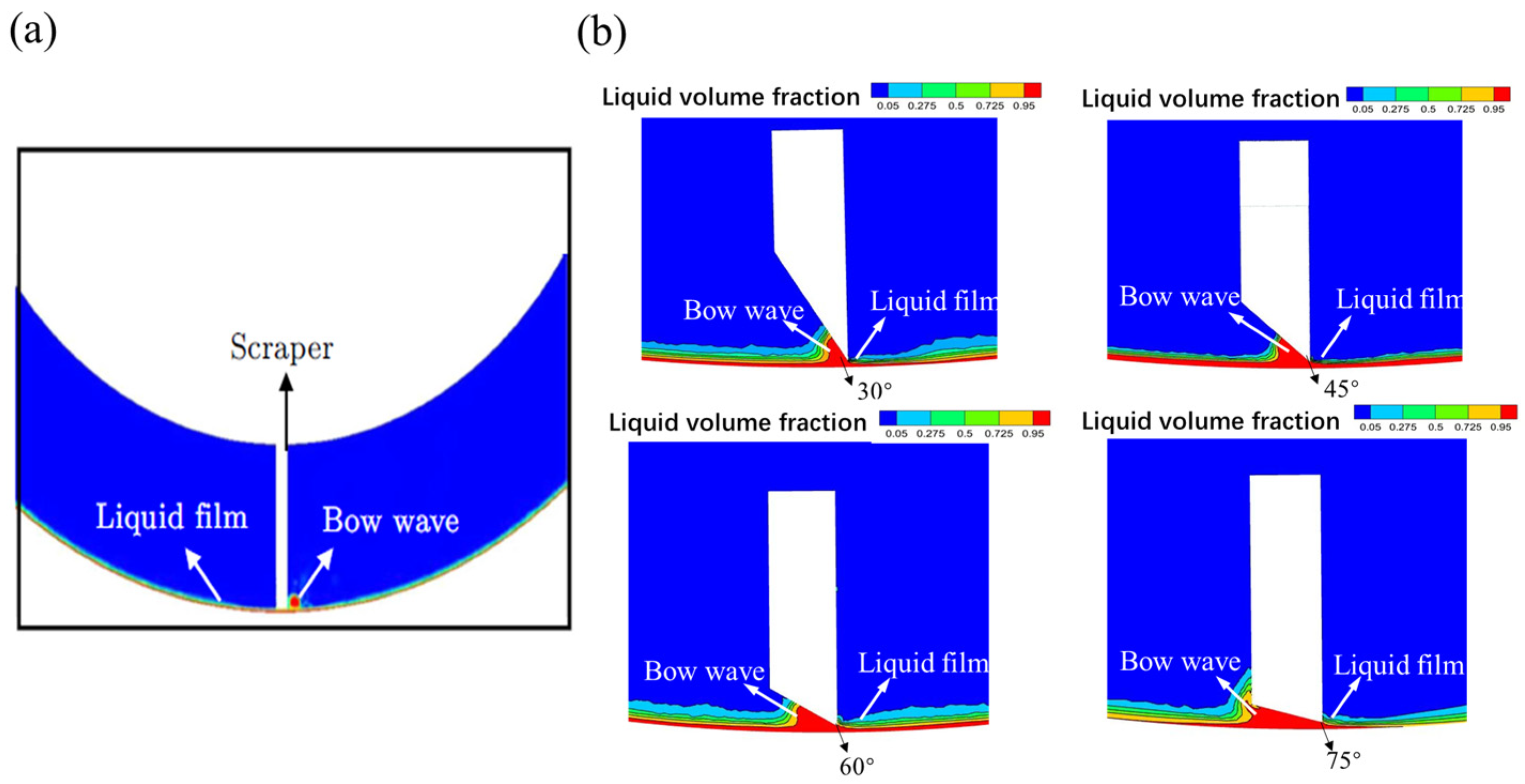
  2. Han, L.; Zhang, S.; Qi, B.-K.; Li, H.; Xie, F.-Y.; Li, Y. Molecular Distillation-Induced Deacidification of Soybean Oil Isolated by Enzyme-Assisted Aqueous Extraction: Effect of Distillation Parameters. Appl. Sci. 2019, 9, 2123. [Google Scholar] [CrossRef]
  3. Pandey, N.K.; Rajeev, R.; Joyakin, C.V.; Anand, P.V.; Velavendan, P.; Kamachi Mudali, U.; Natarajan, R. Development of Solvent Regeneration Process. Desalin. Water Treat. 2014, 52, 7637–7644. [Google Scholar] [CrossRef]
  4. Martins, P.F.; Carmona, C.; Martinez, E.L.; Sbaite, P.; Maciel Filho, R.; Wolf Maciel, M.R. Short Path Evaporation for Methyl Chavicol Enrichment from Basil Essential Oil. Sep. Purif. Technol. 2012, 87, 71–78. [Google Scholar] [CrossRef]
  5. Maziero, E.V.; Salles, R.B.; Tovar, L.P.; Tanabe, E.H.; Bertuol, D.A. Fractionation of Polyethylene Wax by Pilot-Scale Molecular Distillation: New Insights on Process Development. Chem. Eng. Res. Des. 2019, 152, 201–215. [Google Scholar] [CrossRef]
  6. Jahnke, S.; Jasch, K.; Scholl, S. Wiped Film Evaporators: Segmental Assessment of Wetting Behavior and Heat Transfer Performance. Chem. Eng. Res. Des. 2020, 163, 67–75. [Google Scholar] [CrossRef]
  7. Kern, D.Q.; Karakas, H.J. Mechanically Aided Heat Transfer. In Proceedings of the Second National Heat Transfer Conference A.I.Ch.E.-A.S.M.E., Chicago, IL, USA, 18–21 August 1958. [Google Scholar]
  8. Bott, T.R.; Romero, J.J.B. Heat Transfer across a Scraped Surface. Can. J. Chem. Eng. 1963, 41, 213–219. [Google Scholar] [CrossRef]
  9. Paramalingam, S.; Winchester, J.; Marsh, C. On the Fouling of Falling Film Evaporators Due to Film Break-Up. Food Bioprod. Process. 2000, 78, 79–84. [Google Scholar] [CrossRef]
  10. Komori, S.; Takata, K.; Murakami, Y. Flow Structure and Mixing Mechanism in an Agitated Thin-Film Evaporator. J. Chem. Eng. Jpn. 1988, 21, 639–644. [Google Scholar] [CrossRef]
  11. Appelhaus, D.; Jasch, K.; Jahnke, S.; Hassani Khab Bin, H.; Tegethoff, W.; Köhler, J.; Scholl, S. A New Approach to Simulate the Fluid Dynamics in a Wiped Film Evaporator Using Modelica. Chem. Eng. Res. Des. 2020, 161, 115–124. [Google Scholar] [CrossRef]
  12. Moyle, D.T.; Chen, M.-S.; Homsy, G.M. Nonlinear Rivulet Dynamics during Unstable Wetting Flows. Int. J. Multiph. Flow 1999, 25, 1243–1262. [Google Scholar] [CrossRef]
  13. Frías-Esquivel, J.; González-Alatorre, G.; Díaz-Ovalle, C.O.; Lesso-Arroyo, R.; Ramos-Ojeda, E. Hydrodynamic Analysis of the Falling-Film Formation in Evaporators Using CFD Simulation. Food Bioprod. Process. 2017, 101, 56–67. [Google Scholar] [CrossRef]
  14. Dumont, E.; Fayolle, F.; Legrand, J. Flow Regimes and Wall Shear Rates Determination within a Scraped Surface Heat Exchanger. J. Food Eng. 2000, 45, 195–207. [Google Scholar] [CrossRef]
  15. Yataghene, M.; Pruvost, J.; Fayolle, F.; Legrand, J. CFD Analysis of the Flow Pattern and Local Shear Rate in a Scraped Surface Heat Exchanger. Chem. Eng. Process. Process Intensif. 2008, 47, 1550–1561. [Google Scholar] [CrossRef]
  16. Yataghene, M.; Legrand, J. A 3D-CFD Model Thermal Analysis within a Scraped Surface Heat Exchanger. Comput. Fluids 2013, 71, 380–399. [Google Scholar] [CrossRef]
  17. Pawar, S.B.; Mujumdar, A.S.; Thorat, B.N. CFD Analysis of Flow Pattern in the Agitated Thin Film Evaporator. Chem. Eng. Res. Des. 2012, 90, 757–765. [Google Scholar] [CrossRef]
  18. Vita, P.; Gschaider, B.F.W.; Prieling, D.; Steiner, H. Thin Film Flow Simulation on a Rotating Disc. In Proceedings of the European Congress on Computational Methods in Applied Sciences and Engineering (ECCOMAS 2012), Vienna, Austria, 10–14 September 2012. [Google Scholar]
  19. Ishaque, S.; Saeed, M.; Ali, Q.S.; Ullah, N.; Junio, J.C.; Kim, M.-H. CFD Analysis of a Falling Film Evaporator Using the Low-GWP Refrigerant R1336mzz(Z) in High-Temperature Heat Pump Applications. Processes 2025, 13, 2398. [Google Scholar] [CrossRef]
  20. Qin, W.; Li, H.; Luo, M.; Cong, S. Research on the Influence of Fluid Viscosity on the Inlet Flow Parameters of Wiped Film Molecular Distillation. E3S Web Conf. 2024, 522, 01033. [Google Scholar] [CrossRef]
  21. Jasch, K.; Grützner, T.; Rosenthal, G.; Scholl, S. Experimental Investigation of the Residence Time Behavior of a Wiped Film Evaporator. Chem. Eng. Res. Des. 2021, 165, 162–171. [Google Scholar] [CrossRef]
  22. Cortez-González, J.; Murrieta-Dueñas, R.; Alvarado-Rodríguez, C.E.; Segovia-Hernández, J.G.; Hernández, S.; Gutiérrez-Guerra, R. New Approach Lagrangian for Numerical Analysis Within L-V One Equilibrium Stage of a Distillation Column Using the SPH Method. Ind. Eng. Chem. Res. 2024, 63, 21974–21990. [Google Scholar] [CrossRef]
  23. Wang, X.L.; Liu, C.J.; Yuan, X.G.; Yu, K.T. Computational Fluid Dynamics Simulation of Three-Dimensional Liquid Flow and Mass Transfer on Distillation Column Trays. Ind. Eng. Chem. Res. 2004, 43, 2556–2567. [Google Scholar] [CrossRef]
  24. Coroneo, M.; Montante, G.; Paglianti, A.; Magelli, F. CFD Prediction of Fluid Flow and Mixing in Stirred Tanks: Numerical Issues about the RANS Simulations. Comput. Chem. Eng. 2011, 35, 1959–1968. [Google Scholar] [CrossRef]
  25. McKenna, T.F. Design Model of a Wiped Film Evaporator. Applications to the Devolatilisation of Polymer Melts. Chem. Eng. Sci. 1995, 50, 453–467. [Google Scholar] [CrossRef]
  26. Zhang, H.; Xu, M.; Pang, X.; Duan, Z.; Zhang, J.; Meng, X. Analysis of Flow Field Characteristics of the Three-Dimensional Staggered Rotor and Its Influence on Structural Parameters in the Wiped Film Molecular Distillation. Int. J. Chem. React. Eng. 2024, 22, 255–266. [Google Scholar] [CrossRef]
  27. Anand P., V.; Mishra, S.; Gnanasoundari, J.; Rajeev, R.; Desigan, N.; Velavendan, P.; Venkatesan, K.A.; Ananthasivan, K. Wiped Film Evaporator with a Roller Wiper and an Internally Mounted Condenser for the Recovery of TBP and N-DD from Degraded PUREX Solvent. Chem. Eng. Res. Des. 2023, 192, 223–238. [Google Scholar] [CrossRef]
  28. Gu, X.-Q.; Huang, Y.; Zou, K.; Peng, Y.-T. Influence of Liquid Film Shape on Evaporation Performance of Agitated Thin Film Evaporator. Chin. Phys. B 2024, 33, 084701. [Google Scholar] [CrossRef]
  29. Tarokh, A.; Bliss, C.; Hemmati, A. Performance Enhancement of a Two-Phase Closed Thermosyphon with a Vortex Generator. Appl. Therm. Eng. 2021, 182, 116092. [Google Scholar] [CrossRef]
  30. Al-Hassan, T.; Habchi, C.; Lemenand, T.; Azizi, F. CFD Simulation of Creeping Flows in a Novel Split-and-Recombine Multifunctional Reactor. Chem. Eng. Process. Process Intensif. 2021, 162, 108353. [Google Scholar] [CrossRef]
  31. Morison, K.R.; Sellier, M. The Optimal Profile of Weirs for Minimum Static Holdup. Int. J. Multiph. Flow 2012, 39, 245–248. [Google Scholar] [CrossRef]
  32. Yu, S.-H.; Lee, K.-S.; Yook, S.-J. Film Flow around a Fast Rotating Roller. Int. J. Heat Fluid Flow 2009, 30, 796–803. [Google Scholar] [CrossRef]
  33. Yu, J.; Chen, L.; Yuan, X.; Zeng, A.; Ju, J. CFD Simulation of the Heat and Mass Transfer Process during Centrifugal Short-Path Distillation. Chem. Eng. Technol. 2015, 38, 173–180. [Google Scholar] [CrossRef]
  34. Xiang, A.; Xu, S. Comparison of Two Turbulent Models in Simulating Evaporating Liquid Film in a Wiped Molecular Distillator. Sc. China Ser. B-Chem. 2005, 48, 183–188. [Google Scholar] [CrossRef]
  35. Mabit, J.; Fayolle, F.; Legrand, J. Shear Rates Investigation in a Scraped Surface Heat Exchanger. Chem. Eng. Sci. 2003, 58, 4667–4679. [Google Scholar] [CrossRef]
  36. Tao, X.; Qi, H.; Guo, Z.; Wang, J.; Wang, X.; Yang, J.; Zhao, Q.; Lin, W.; Yang, K.; Chen, C. Assessment of Measured Mixing Time in a Water Model of Eccentric Gas-Stirred Ladle with a Low Gas Flow Rate: Tendency of Salt Solution Tracer Dispersions. Symmetry 2024, 16, 1241. [Google Scholar] [CrossRef]
  37. Tkáč, A.; Cvengroš, J. Continuous Processes in Wiped Films. 1. Multistage Molecular Distillation in an Arrangement with a Single Convex-Shaped Evaporator Body. Ind. Eng. Chem. Proc. Des. Dev. 1978, 17, 242–245. [Google Scholar] [CrossRef]
  38. Lopez-Toledo, J. Heat and Mass Transfer Characteristics of a Wiped Film Evaporator. Ph.D. Thesis, The University of Texas at Austin, Austin, TX, USA, 2006. [Google Scholar]
  39. Hisashi, M.; Masamichi, Y.; Takeshi, Y.; Tatsuo, N. Heat Transfer Correlation in High Prandtl (High Schmidt) Number Fluid in Votator Type Scraped Surface Heat Exchanger. J. Chem. Eng. Jpn. 1997, 30, 545–549. [Google Scholar] [CrossRef][Green Version]
Figure 1. Geometric Diagram of the Wiped-Film Molecular Distiller: (a) 3D model, (b) scraper structure, (c) scraper geometry.
Processes 14 01447 g001
Figure 2. 3D Mesh Generation Diagram.
Processes 14 01447 g002
Figure 3. Mesh-Independence Verification Based on the Average Scraper Torque and the Area-Weighted Average Radial Velocity at z = 60 mm.
Processes 14 01447 g003
Figure 4. Qualitative comparison of canonical wiped-film flow topology and simulated liquid-phase trajectories: (a) Schematic depiction of the characteristic flow pattern reported by Komori, illustrating head-wave formation and spiral liquid-film transport; (b) Liquid-phase trajectories obtained from the present CFD simulation in the corresponding near-scraper region. The arrows in both panels indicate the direction of fluid motion, highlighting the spiral downward transport along the wall and the local recirculation in the head-wave region.
Processes 14 01447 g004
Figure 5. Comparison of Inline Scraper and Grooved Scraper Conditions: (a) Liquid Film Fraction, (b) Liquid Film Flow State, (c) Liquid Film Shear State. Color scale definition: in (a) the color represents liquid volume fraction (blue: lower; red: higher); in (b) the color represents unit Reynolds number (blue: lower; red: higher); and in (c) the color represents strain-rate magnitude (blue: lower; red: higher), as indicated by the color bar.
Processes 14 01447 g005
Figure 6. Turbulent Kinetic Energy (TKE) Distribution for: (a) the inline scraper and (b) the grooved scraper. Color bar units: m2s−2. (a) TKE range: 0.005–0.016 m2s−2; (b) TKE range: 0.06–0.25 m2s−2.
Processes 14 01447 g006
Figure 7. Average Radial and Axial Velocities at Five Axial Planes for Different Groove Widths: (a) Radial velocity, (b) Axial velocity.
Processes 14 01447 g007
Figure 8. Flow Field Structures Under Different Groove Widths. Upper row: Q-criterion iso-surfaces (Q = 0.015 s−2) colored by velocity magnitude, showing vortex-core morphology for (a) W = 2 mm, (b) W = 7 mm, and (c) W = 10 mm. Lower row: corresponding velocity magnitude contour maps on the mid-height cross-sectional plane (z = 60 mm). Color scale: 0–0.600 m s−1 (blue: low velocity; red: high velocity), consistent across all panels.
Processes 14 01447 g008
Figure 9. Mixing Intensity and Wall Renewal Frequency Gain.
Processes 14 01447 g009
Figure 10. Total torque on the scraper wall region under different groove widths. The bar chart represents the absolute torque values (N·m) for each groove-width case, while the line plot represents the incremental increase in torque (%) relative to the previous groove-width case. This comparison illustrates how the mechanical energy transfer from the scraper to the fluid evolves with increasing groove width.
Processes 14 01447 g010
Figure 11. Diagram of Different Scraper Angles.
Processes 14 01447 g011
Figure 12. Comparison of flow characteristics at different scraper tip included angles: (a) axial velocity variation along the axial direction; (b) radial velocity variation along the axial direction; (c) average liquid film thickness under different tip included angles. The green triangle with a dotted line indicates the average value of the corresponding parameter for each case, highlighting the overall trend under different scraper angles.
Processes 14 01447 g012
Figure 13. Relationship Between Vorticity Characteristics and Scraper Tip Angle: (a) Vortex area; (b) average vorticity magnitude.
Processes 14 01447 g013
Figure 14. Flow field structures under different scraper tip included angles. (Upper row): Q-criterion iso-surfaces (Q = 0.015 s−2) colored by velocity magnitude for θ = 30°, 45°, 60°, and 75°. (Lower row): corresponding velocity magnitude contour maps on the mid-height cross-sectional plane (z = 60 mm). Color scale: 0–0.600 m s−1 (blue: low velocity; red: high velocity), consistent across all panels.
Processes 14 01447 g014
Figure 15. Liquid Volume Fraction Distribution at the Scraper Leading-Edge Region Under Different Tip Included Angles. Left (a): schematic depiction of the canonical wiped-film flow topology reported by Komori, showing the expected bow-wave and liquid-film features as a qualitative reference. Right (b): zoomed CFD contour maps of the scraper tip region for θ = 30°, θ = 45°, θ = 60°, and θ = 75°, with key features annotated (“Bow wave” and “Liquid film”). Color scale: liquid volume fraction 0.05–0.95 (blue: gas-dominant; red: liquid-dominant), consistent across all four panels.
Processes 14 01447 g015
Table 1. Scraper dimensions and investigated parameter ranges.
ParameterSymbolValueUnit
Long side length a 29.2mm
Short side length b 21.2mm
Scraper thickness d 8.0mm
Scraper-wall gap-0.8mm
Baseline groove width (inline scraper) W 0.0mm
Baseline tip angle θ 45deg
Groove width range W 2.0–10.0mm
Tip angle range θ 30–75deg
Outer wall diameter D o 400.0mm
Inner wall diameter D i 310.0mm
Table 2. Fluid Physical Properties and Operating Conditions.
ParameterValueUnit
Representative case-study mixture compositionEthylene glycol (42.0 mol%), Glycerol (58.0 mol%)-
Density ( ρ )1196.0kg/m3
Dynamic viscosity (μ)0.222Pa·s
System operating pressure (absolute)15.0Pa
Heating wall temperature350K
Condensation surface temperature240K
Mass flow rate0.15kg/min
Rotational speed120r/min
Table 3. Summary of the Three-Level Quantitative Validation Framework.
MetricCFD ResultComparison ValueRelative Deviation (%)
Near-wall shear intensityΦ = 1134.91Φ ≈ 1000–3000-
Liquid-film thickness δ e q = 1.278 mm δ e q   = 1.257 mm1.70
Scraper torque T C F D = 0.0205 N ⋅ mT = 0.0237 N ⋅ m13.3
Disclaimer/Publisher’s Note: The statements, opinions and data contained in all publications are solely those of the individual author(s) and contributor(s) and not of MDPI and/or the editor(s). MDPI and/or the editor(s) disclaim responsibility for any injury to people or property resulting from any ideas, methods, instructions or products referred to in the content.