Review

A Novel Permeable Reactive Barrier Approach for Phenolic and Nitrogen Pollutants Removal via Direct Fuel Cells with Its Electricity Retrieval


1
School of Engineering, University of Warwick, Coventry CV4 7AL, UK
2
School of Ecology and Environment, North China University of Water Resources and Electric Power, Zhengzhou 450046, China
3
Zhejiang Environmental Monitoring Center, Hangzhou 310013, China
4
Liangzhu Laboratory, Zhejiang University, Hangzhou 311121, China
5
Department of Environmental Engineering, State Key Laboratory Clean Energy Utilization, Zhejiang University, Hangzhou 310058, China
*
Authors to whom correspondence should be addressed.
These authors contributed equally to this work.
Processes 2026, 14(8), 1252; https://doi.org/10.3390/pr14081252
Submission received: 22 December 2025 / Revised: 31 March 2026 / Accepted: 9 April 2026 / Published: 15 April 2026
(This article belongs to the Special Issue State of the Art of Waste Utilization and Resource Recovery)

Abstract

Permeable reactive barrier (PRB) is an in situ remediation of contaminated sites mostly suitable for halogenated pollutants like halo-hydrocarbons reduced by zero-valent irons (ZVI) developed during early 1990’s. However, remediation of some nitrogen-pollutants like ammonia and urea is unsuccessful due to lack of reactants. Most recent advanced direct ammonia/urea fuel cells utilize indirect hydrogen within ammonia/urea molecules to generate electricity. Herein, a comprehensive study based on the chosen design, working principles, advantages and disadvantages of direct ammonia fuel cells for new approach of PRBs for denitrifying nitrogen-contaminant is summarized. Most surveys are carrying out in our laboratories and this work aims to review the most recent advances in ammonia fuel cells integrated with PRBs and demonstrates the proximity of this technology to future applications. Meanwhile, several challenges such as how to accumulate ammonia and urea in order to achieve satisfying energy recovery, oxidants formation, power densities and long term stability are also summarized in this review.

1. Introduction

Groundwater is vital to human life and production [1,2,3,4]. However, inorganic and organic pollution caused by human activities continues to pose a serious threat to the quality of groundwater resources worldwide [5,6,7,8]. For example, halogenated hydrocarbons, which serve as excellent organic solvents in industry, various widely used heavy metals, and nitrogen-containing compounds such as nitrates and ammonium salts, are all susceptible to serious groundwater pollution. Furthermore, most of these pollutants have toxic effects such as teratogenicity, carcinogenicity, and mutagenicity, posing serious risks to human health and the ecological environment [9,10]. Consequently, a range of groundwater remediation technologies have been developed [11,12,13,14,15,16] and remain a sought-after goal for researchers in the field of science and technology [17,18,19,20]. Among these, permeable reactive barrier (PRB) technology offers relatively low cost, simple process, and minimal secondary contamination. Furthermore, PRB is an in-situ remediation technology, attracting considerable attention due to its high efficiency, cost-effectiveness, and environmental friendliness [21,22,23,24,25].
The working principle of PRB technology is to install a wall filled with a reactive medium underground to intercept the groundwater pollution plume. After the pollution plume passes through the reactive medium under the action of the natural hydraulic gradient, the pollutants are converted into an environmentally acceptable form or the concentration reaches the relevant environmental standards. The two most common types of PRBs used in field applications are continuous type and funnel-type [26], including hybrid approaches that combine with electro-remediation or bioremediation to improve their effectiveness [27].
The reactivity of common barrier materials (e.g., iron metal) with chlorinated compounds was recognized as early 1925 in-situ applications were apparently not being considered until recently. The sharp increase in interest in PRBs during the early 1990’s is attributable to a number of conference studies, but the perhaps mostly to those of Robert Gillham and co-workers, who conducted the first field application of zero-valent iron-based PRB (ZVI-PRB) technology in 1991 at a military base in Borden, ON, Canada, for the in-situ remediation of groundwater contaminated with tetrachloroethylene (PCE) and trichloroethylene (TCE) [28]. Since then, PRB technology has been used at more than 90 sites in the United States and more than 200 sites worldwide, which are mostly ZVI-PRB [29]. Most of these ZVI-PRBs are used to remediate groundwater contamination with chlorinated hydrocarbons [30].
PRBs are generally effective, but loss of ZVI activity, deterioration of hydraulic performance, and design defects can cause PRB failure [31], shortening the service life of ZVI-PRBs. Moreover, additional iron metal changes the property of the groundwater as well as soil. Noticeably, ammonium salts exhibit same properties of ZVI as an electron donor, but not active as the ZVI is. That makes it difficult to remove ammonia using current PRB’s design. In this perspective review, a new approach was introduced to adopt fuel cell serves as PRB media to remove ammonia while generating electricity.

1.1. Reaction and Transformation of ZVI as an Electron Donor in PRB

During the ZVI-PRB remediation of groundwater, complex interfacial reactions such as dissolution, adsorption, redox, and precipitation can occur simultaneously or sequentially on the ZVI surface [32]. Among them, redox is the main reaction mechanism, and ZVI acts as an electron donor to provide electrons for transfer to nitrate molecules. The extent to which reactions such as coprecipitation, chemical adsorption, and electrostatic physical adsorption play crucial roles in the remediation process depending on the interaction between nitrate and iron corrosion products. The generation of various iron corrosion products is significantly affected by pH value [33].
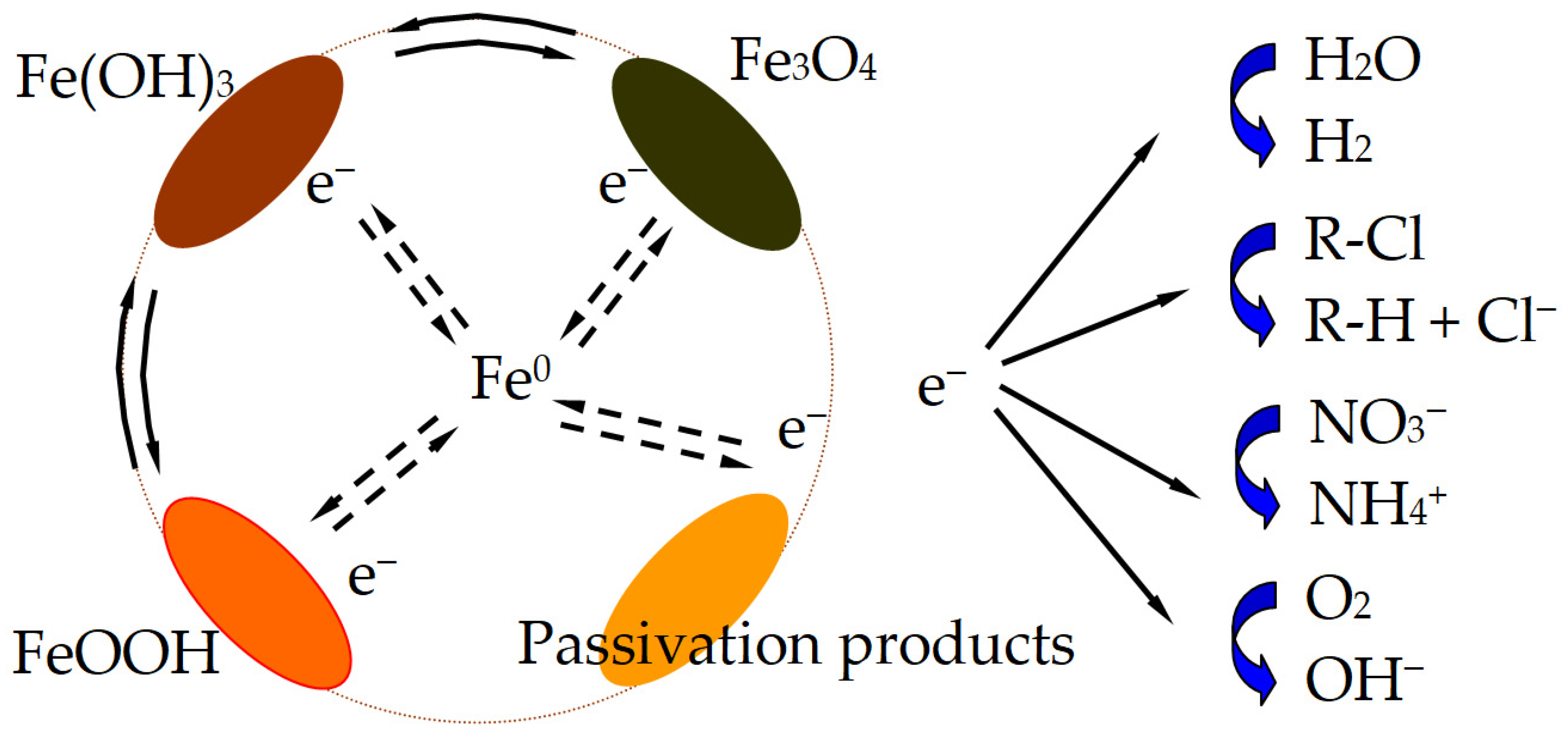
The corrosion of ZVI promotes the redox reaction, but the interaction between ZVI and solutes in groundwater affects the redox reaction, which in turn affects the efficiency and stability of ZVI-PRB in remediating chlorinated hydrocarbon pollution. The corrosion of ZVI in groundwater and its oxidation and reduction reactions with chlorinated hydrocarbons are shown in Table 1 [33]. The ability of solutes in contaminated groundwater to compete with ZVI for electron reduction depends on the thermodynamic properties of the electron acceptor and is affected by the standard electrode potential (E0). If the electrode potential is higher, the ability of the electron acceptor to compete for electron reduction is stronger. For example, NO3 ions in groundwater has a higher oxidizing property and will react preferentially with ZVI, thereby affecting the reactive sites on the surface of ZVI, as shown in Figure 1 [34]. In addition, the electron transfer of ZVI is also affected by the concentration of various electron acceptors and external environmental conditions. Therefore, it is necessary to conduct a supplementary analysis from a kinetic perspective. It is worth noting that the concentration of various electron acceptors is affected by multiple factors such as the solubility of the aquifer and changes over time.
Early ZVI-PRBs were primarily composed of granular ZVI, with purity generally greater than 95%. More recent ZVI-PRBs typically mix granular ZVI with sand, gravel, pumice, and other materials to ensure uniform distribution of ZVI within the PRB and prevent clogging of the PRB’s inlet side [25,35]. ZVI mixed with carbonaceous materials such as activated carbon has also been shown to be an effective hybrid material, significantly outperforming single materials in removing TCE from groundwater under both static and dynamic conditions [36].

1.2. Ammonium Salt as Electron Donors in PRBs

Same as ZVI, ammonium as an electron donor provides reduction of electron acceptors such as nitrate and heavy metals, requiring catalysts either biocatalysis or nanocatalysis. The reaction equation using ammonium as an electron donor primarily involves the anaerobic ammonium oxidation (ANAMMOX) process, the core reaction of which is:
2NH4+ → N2 + 6e + 8H+
ANAMMOX reaction NH4+ serves as the electron donor and NO2 serves as the electron acceptor, generating N2 through a redox reaction:
2NO2 + 8H+ + 6e → N2 + 4H2O
The overall reaction is:
NH4+ + NO2 → N2 + 2H2O
This reaction is catalyzed by anaerobic ammonium-oxidizing bacteria under anaerobic conditions, with electrons transferred from ammonium ions to nitrite ions. In the Equations (1) and (2), the electron transfer mechanism will be:
(1)
The nitrogen atom in NH4+ binds to the hydrogen ion via a coordination bond, forming the ammonium ion (NH4+). The nitrogen atom has a lone pair of electrons, making it an electron donor.
(2)
Biological Function: Anaerobic ammonium-oxidizing bacteria metabolize NH4+ to N2 and simultaneously oxidize NO2 to NO3, achieving denitrification in the nitrogen cycle.
Both NH4+ and ZVI can reduce nitrates, but cannot reduce pollutants such as chloromethane, dichloromethane, and 1,2-dichloroethane (1,2-DCA). These pollutants are more easily degraded by bioreductive dechlorination [37]. The use of a mixture of ZVI and polyhydroxybutyrate (PHB) in PRB can improve the removal performance and life of ZVI for 1,2-DCA. PHB as a carbon source can enhance the removal of 1,2-DCA by bioreduction. This mixture expands the applicability of PRB technology and improves its effectiveness in treating complex pollutant plumes [38]. A mixture prepared by mixing compost with lignite, zeolite, and diatomaceous earth can effectively remove TCE. The compost-lignite (volume ratio 1:3) material can significantly increase the hydraulic conductivity by one order of magnitude. At the same time, the production of the degradation product dichloroethylene proves the reduction and dechlorination of TCE [39]. It should be noted that the key to the successful application of microorganisms is to create and maintain suitable conditions for the microorganisms, such as temperature, pH value, stable pollution components, and sufficient nutrients [40].
Mixed materials can achieve relatively long-term hydraulic performance, but the corrosion and passivation of ZVI itself and the continuous activity of microorganisms will weaken or lose the hydraulic performance of PRB projects, resulting in failure. Therefore, further research is needed to study the long-term hydraulic performance changes of various mixed materials in actual complex groundwater environments.

1.3. Preparation of Core-Shell Materials Loaded with ZVI and Ammonium

Ammonium salts are easily soluble in water and lost, while adsorbent materials can be immobilized. Core-shell materials are materials with spherical, rod-shaped, layered or porous structures as core materials, and various functional materials are loaded on the surface of the core materials to form a core-shell structure. Core-shell materials can solve the problems of aggregation and passivation of emerging nanomaterials (such as nZVI), and the core and shell can synergistically treat pollutants. At present, the application of core-shell materials in environmental pollution is relatively small compared with the biomedical field [41]. Researchers mostly use ZVI as the shell material and mineral materials and carbonaceous materials as the core material. This type of core-shell material can make ZVI more evenly distributed in the PRB, and it itself has adsorption properties to remove chlorinated hydrocarbon pollution in groundwater.
Mineral materials have the characteristics of large specific surface area, easy acquisition, low cost and excellent mechanical properties, so they can be loaded with ZVI to construct core-shell materials as PRB reaction media. The aerosol-assisted method was used to prepare spherical silica-loaded nZVI core-shell materials for the removal of halo-hydrocarbons from groundwater, which significantly optimized the reduction performance, adsorption performance, distribution performance, and migration performance of the core-shell materials in aquifers [42]. Clay minerals such as bentonite loaded with nZVI or nZVI/Ni can effectively couple reduction dechlorination and adsorption to remove various pollutants in groundwater [43,44]. In the research on core-shell materials, no signs of nZVI particle aggregation or deactivation due to oxidative shell have been found.
Carbonaceous materials have great advantages in the selection of PRB reaction media due to their excellent adsorption performance and environmental friendliness. Using lignin and magnetite as raw materials, biochar loaded with nZVI was prepared by pyrolysis to form a core-shell material that can adsorb and degrade halo-hydrocarbons in water and is very outstanding in terms of cost control and pollution remediation effect [45]. Biochar can be successfully loaded with nZVI using the ball milling method. Under the action of water flow, the core-shell material can maintain good performance in removing halo-hydrocarbons. At the same time, as the carbon-iron ratio decreases, the migration loss rate of the core-shell material increases.
Due to the disadvantages of complex preparation process, high cost and numerous chemical reactions, core-shell materials are currently mostly studied in the laboratory. How to simplify the process and reduce costs while maintaining high removal performance, and how to quantitatively study the performance utilization of different repair components in the core-shell material, these problems need to be solved [46].

2. Design of PRB Using Fuel Cell to Remove Pollutants with Its Electricity Retrieval

The theoretical design of a dynamoelectric fuel cell is fundamental, and the design of the diaphragm structure is crucial for its effective operation. This section presents theoretical analysis and design of monometallic or bimetallic dynamoelectric fuel cells using direct urine/ammonia fuel cell to eliminate ammonium salts. The design of diaphragms for bimetallic ionic liquid, bimetallic buffer, bipolar membrane buffer, and membraneless ion transport is outlined, along with the main technical approaches and evaluation methods for achieving simultaneous power generation and pollution removal in each dynamoelectric fuel cell.

2.1. Design of Dynamoelectric Fuel Cells, Theoretical Analysis

Thermodynamically, the electrode pair reaction that makes up a galvanic cell is: E = −ΔG/nF. Current can only be generated when E > 0 and ΔG < 0, that is, when there is a potential difference between the anode and cathode. The smaller the ΔG value, the greater the likelihood of this occurring, meaning a higher designed electromotive force (EMF), which is more conducive to energy conversion and pollution removal. Therefore, the selection of the anode and cathode electrode pair is crucial—that is, the pairing of fuel and heavy metal ions is normally chosen to achieve a high electromotive force.
The electromotive force is calculated based on thermodynamic data. Under isothermal, isobaric, and reversible conditions, the electrochemical reaction aA + bB = cC + dD occurs in the cell. The thermodynamic equation for this reaction is shown in (4) and (5):
ΔG = ΔHTΔS
Under standard conditions, it is written as,
ΔG0 = ΔH0TΔS0
where ΔG represents the Gibbs free energy change; ΔH represents the enthalpy change, the energy released by the chemical reaction; ΔS represents the entropy change; T represents the absolute temperature; and 0 represents the standard state, 25 °C, and the standard activity. ΔG represents the useful work of the chemical reaction. The change in the Gibbs function of the chemical reaction, ΔG, is equal to the work done by the battery, i.e.,:
ΔG = −nFE
Under standard conditions, it is written as,
ΔG0 = −nFE0
where E is the electromotive force of the reversible cell; F is the Faraday constant; and n is the number of electrons transferred during the reaction. Open-circuit voltage (OCV) refers to the cell voltage when no current flow, which is theoretically close to the cell’s electromotive force.
Fuel electrode polarization is unavoidable due to electrode dynamics, requiring a catalyst to reduce the energy barrier. Therefore, the design and preparation of electro-catalytic anodes are crucial for efficient power generation in heavy metal-electrode fuel cells. Based on the principles of primary cells and fuel cells, heavy metal-electrode fuel cells with varying redox potentials can be constructed to achieve both power generation and removal of heavy metals.
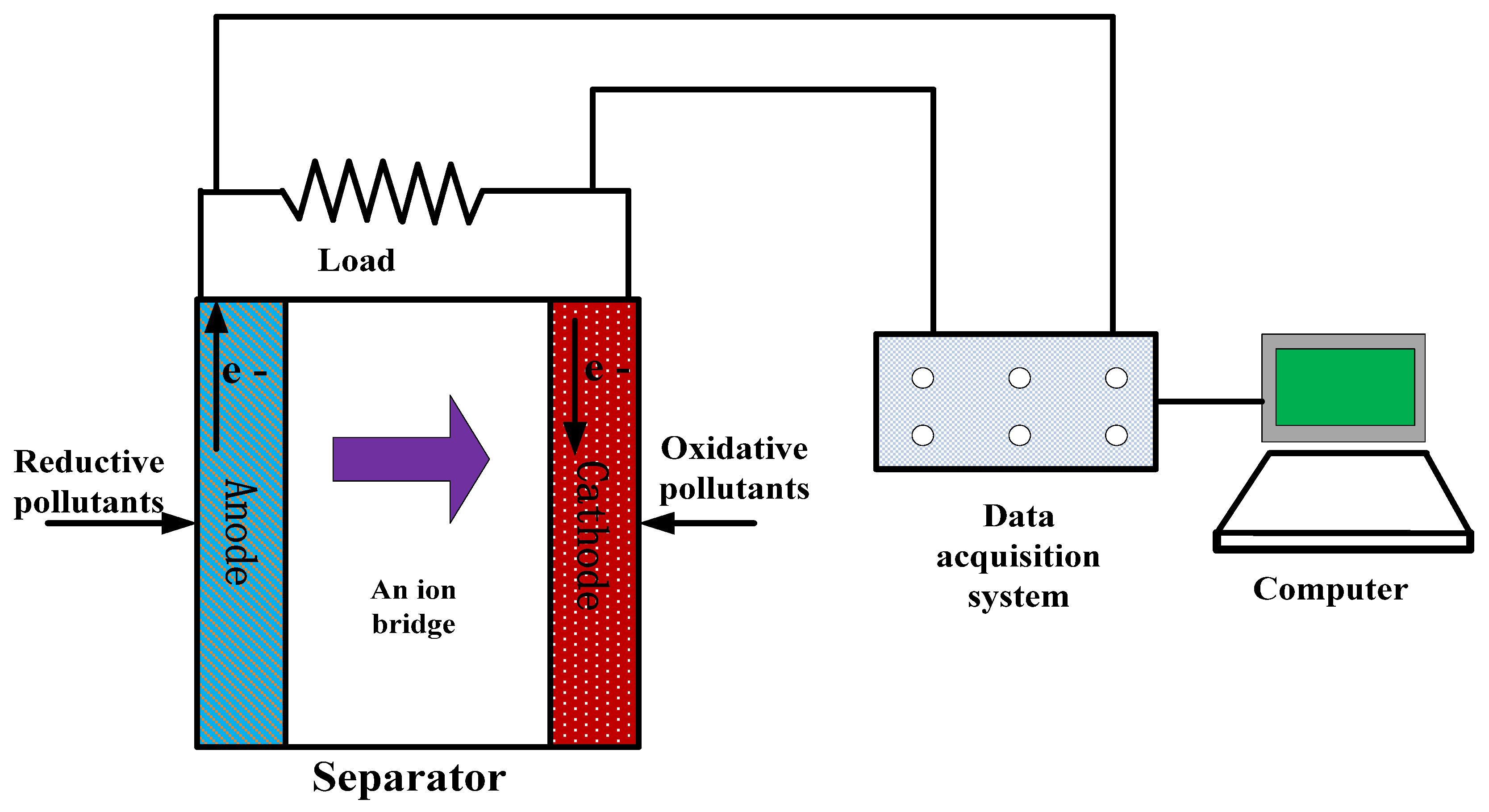
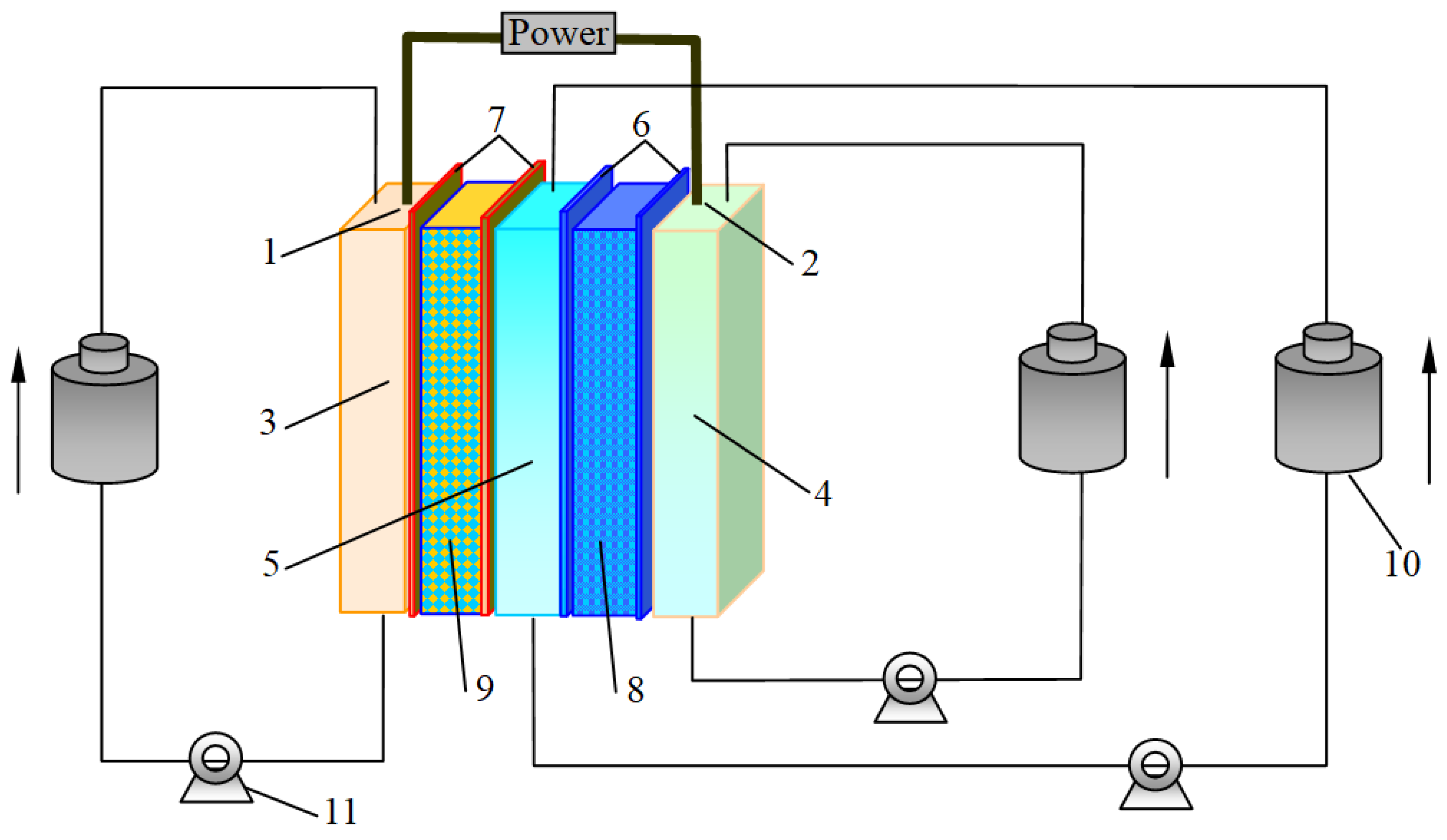
Urea (or ammonia) has a higher electrochemical activity toward nickel than precious metals, and the catalytic activity of nano-nickel-carbon catalysts is even more pronounced. Direct urea fuel cells (DUFCs) have directly demonstrated that urea can be used as a fuel to provide electrons to the cathode oxidant under the catalysis of nickel catalysts. Therefore, constructing an efficient nano-nickel-carbon catalytic anode is crucial for achieving the electroreduction and removal of nitrates at the cathode of urine-nitrate electrodes. The electrode reaction of urea at the catalytic anode is shown in Equation (8) and the experimental setup shows in Figure 2.
CO(NH2)2 + 6OH → N2 + CO2 + 5H2O + 6e       E0= −0.746 V vs. SHE

2.2. Modification of Dynamoelectric Fuel Cells Used as PRB

It should be noted that an oxidative pollutants or electron acceptor is needed to fill in the cathode. Practically, air (O2) is filled into cathode chamber to accept electrons generated in anode via external electrical circuit.
Due to an electromotive force between the two electrodes, urea or ammonia reactions are accelerated.
(1)
Voltage and current
Electrochemical cell voltage parameters include cell electromotive force, open-circuit voltage (VOCV) and output voltage (Vout). The cell electromotive force is calculated from thermodynamic data. The output voltage (Vout) of the battery can be expressed by Equation (9) [47]:
Vout = VOCVη = Vtherm − Vpar − η
Vout—cell voltage when current flows, V;
VOCV—open-circuit voltage (OCV), V, the voltage when no current flows, close to the thermodynamic voltage;
η—polarization potential that deviates from the equilibrium potential, including activation polarization, ohmic polarization and concentration polarization;
Vtherm—thermodynamic voltage, V, which can be calculated according to the Nernst equation.

2.3. Denitration of Landfill Leachate Through Ammonia/Nitrate Fuel Cell

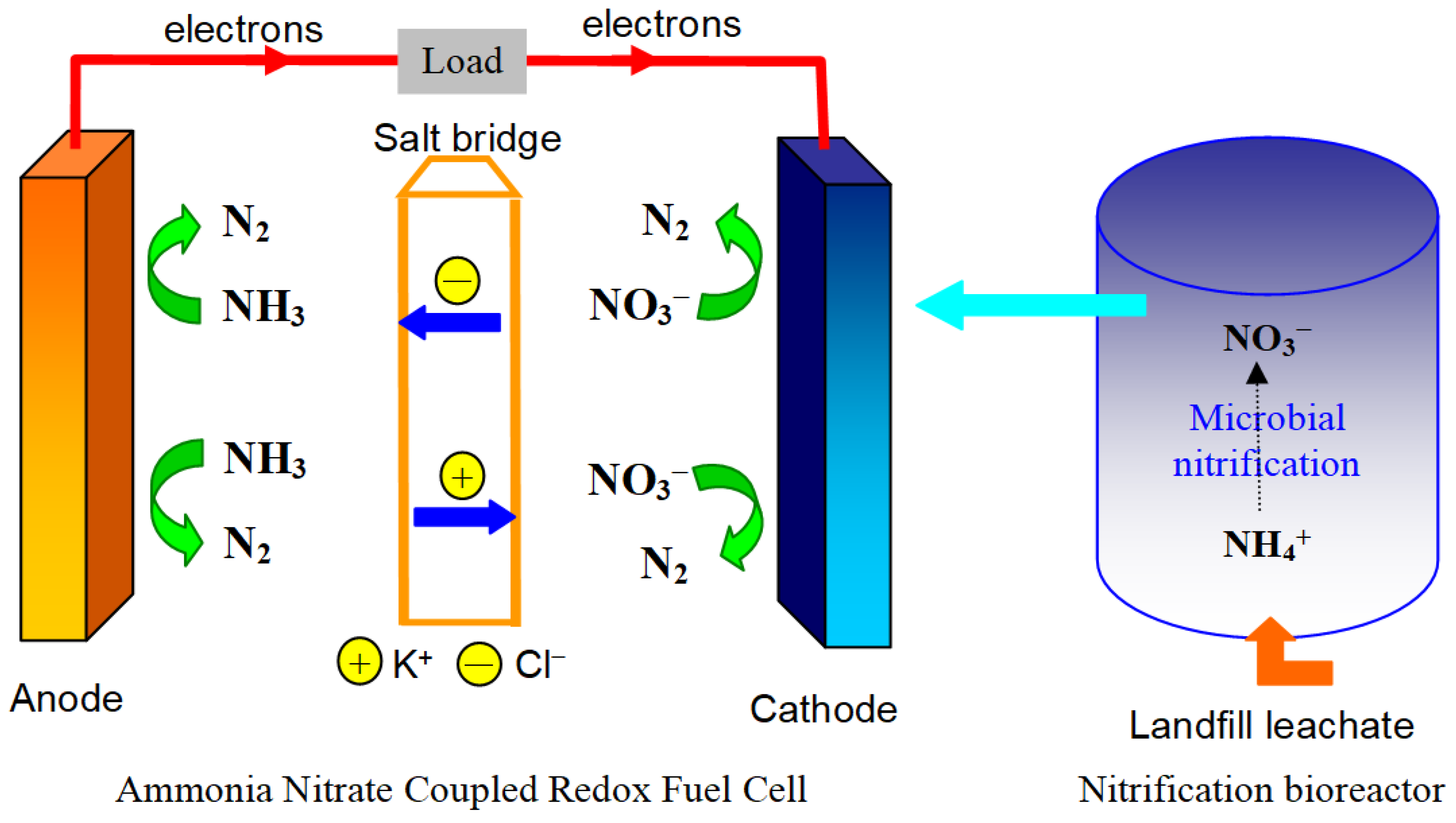
Highly concentrated ammonia nitrogen exists in the landfill leachate. By using an ammonia/nitrate coupled redox fuel cell, simultaneously nitrogen removal with electric power generation has been successfully achieved. Figure 3 shows the ammonia/nitrate coupled redox fuel cell design. In the cell, ammonia is oxidized at anodic compartment and nitrate is reduced at cathodic compartment spontaneously by electrocatalysis.
This preliminary approach is a promising way to treat N-rich wastewater. Compared with biological method, it can be controlled simply by using various operation condition according to different pollutants-containing water and can tolerate high concentration of nitrate. For a practical application to denitrate ammonia contaminants, there still remains many technical challenges to be addressed. One of the options is to use membrane technology. Besides, a better structure design is also essential to improve the cell performance.

2.4. Fuel Cell as Feasible Permeable Reactive Barrier for the Removal of Phenol

Much pollution leachate will be inevitably produced in polluted sites [49,50]. A large number of organic pollutants in leachate are one of the key pollutant categories of leachate pollution. Among these organic pollutants, phenolic pollutants are widely present and have a high concentration. Specifically, phenol, which is highly poisonous for the ecosystem, is often derived from chemical plants, municipal waste treatment plants, etc. [51,52]. In some cases, phenol is identified as one of the characteristic pollutants in groundwater in landfills [53]. Phenol is also a priority pollutant screened by U.S. EPA [54,55]. Stringent environmental regulations have drawn the attention of environmental researchers to develop efficient technologies to control phenol.
In a permeable reactive barrier system for the groundwater pollution remediation, the mechanisms of adsorption and bioremediation are usually used for the control of organic pollutants. After organic pollutants are adsorbed by the adsorbent material, the adsorbent material need to be transferred out of the contaminated sites and off site treatment is required to convert the organic pollutants into small molecule inorganic substances completely, making the overall remediation process complex. For the bioremediation of organic pollutants, the activity of microbial communities is limited and can be affected by environmental conditions. However, some pollutants could inhibit the activity of microorganisms, so it is usually difficult to obtain a rapid rate of removal.
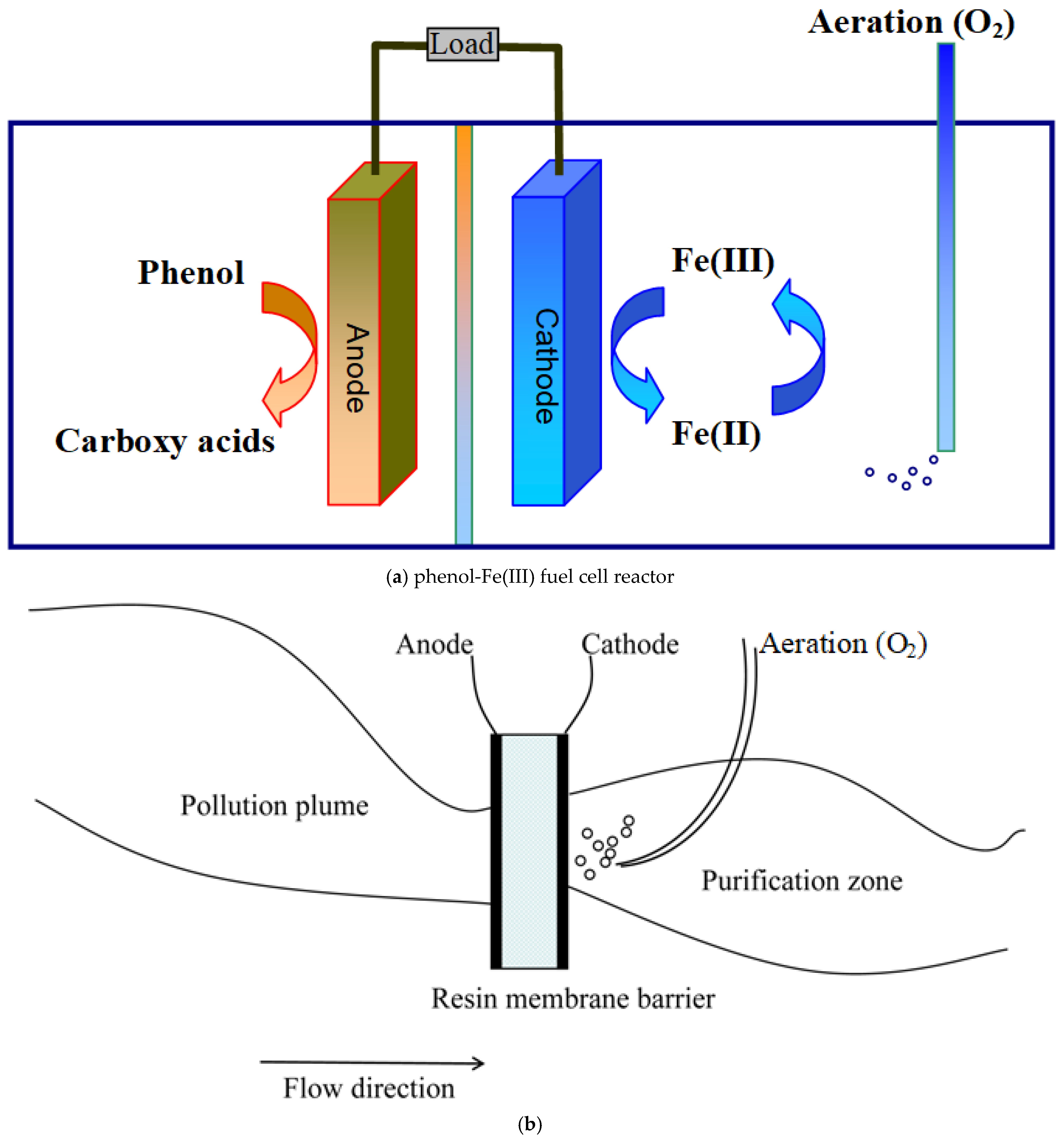
Among heavy metal pollutants detected in the groundwater near municipal solid waste landfills (MSWLs) [56,57], iron is a major component with a relatively high concentration [58]. Therefore in this lab-scale experiment work, we try to use Fe(III) as the oxidant to assemble a self-powered redox fuel cell with phenol served as the fuel for the removal of pollutants (Figure 4). Additionally, the reduced iron species (Fe(II)) can be oxidized to high-valent iron species (Fe(III)) under the action of oxygen, realizing the multiple use or recycle of iron species. The work has demonstrated the application of PRBs in groundwater remediation with the recycle use of oxidants.

3. Accumulation of Contaminants via Electrochemical Deionization and Ingathering

3.1. Pre-Concentration of Ionic Substances

Contaminations such as ammonia on sites to be treated vary among the sources of wastewater or groundwater, often possessing at very low concentration [59]. The treatment of ammonia from wastewater is still a challenging and energy-intensive, often requiring specialized processes and technologies [60]. To meet the requirements of PRBs with electricity generation via a direct fuel cell, a pre-concentration procedure is practically necessary.
Among various technologies of recovery or pre-concentration processes, an electrochemical deionization method called electrodeionization (EDI) is preferable. Electrodeionization, also known as packed bed electrodialysis, is a water treatment process that combines electrodialysis with ion exchange technology [61,62,63,64,65]. Its principle is to fill the diaphragm of the electrodialyzer with ion exchange resin, and achieve ion migration and resin regeneration simultaneously through the action of the electric field, without the need for chemical regeneration agents. The concept of this technology was originally developed for the preparation of pure water, and the purpose of filling with ion exchange resin is to increase the conductivity of water [66,67,68,69,70].
Compared with ordinary electrodialysis, the dilute chamber is filled with ion exchange resin, which greatly improves the conductivity between membranes, significantly enhances the ion migration from the solution to the membrane surface, removes the ion deficiency phenomenon in the concentration retention layer on the membrane surface, and increases the limiting current density; compared with ordinary ion exchange. Due to the high potential gradient between membranes, water is forced to dissociate into H+ and OH. On the one hand, H+ and OH ions participate in the load current, and on the other hand, they can play a key role in on-site regeneration of the resin. Therefore, EDI does not need to regenerate the resin, which can save the acid and alkali storage tanks required for ion exchange and reduce environmental pollution.
Obviously, it has already been noted that the EDI is actually a membrane separation and desalination process that concentrates ions in a resin layer. It is a green and environmentally friendly technology. It utilizes the polarization phenomenon during electrodialysis to electrochemically regenerate the ion exchange packed bed, combining the advantages of electrodialysis and ion exchange while overcoming the disadvantages of both. Continuous electrodeionization (CDI) utilizes mixed ion exchange resins to adsorb anions and cations in the feed water. These adsorbed ions are then removed through the anion and cation exchange membranes under the action of a direct current voltage.
In this process, the ion exchange resins are continuously regenerated electrically, eliminating the need for acid and alkali regeneration. This new technology can replace traditional ion exchange devices. EDI utilizes anion and cation membranes in a symmetric stacking configuration, with anion and cation resins sandwiched between the membranes. Under the action of a direct current voltage, anion and cation exchange takes place, respectively. Simultaneously, the voltage gradient causes dissociation of water to generate large amounts of H+ and OH, which continuously regenerate the anions and cations in the membranes. Since EDI is constantly exchanging and regenerating, in addition to easily producing high-purity water, recyclable salt or ion products are also obtained, which are pre-concentrated. Nowadays, many modified EDI processes have been developed for recovery of useful chemicals like ammonia [71,72,73].
Nevertheless, since the actual sample on sites always contains a large amount of divalent alkaline earth metal elements such as calcium and magnesium, precipitates will form on the alkaline cathode electrode. This requires the use of electrodes reversal to change the acidity and alkalinity of the cathode electrode to eliminate these precipitates. Therefore, not only is the operation complicated, but the service life will also be reduced.
To this end, in our research group developed an EDI device with new configuration of electrode arrangements, so that the anodic electrode chamber is always in an acidic state, thereby avoiding the precipitation of cations on the electrodes (Figure 5).
Notably, EDI always has concentration polarization, which makes the concentration ratio only about 10 times. In order to greatly increase the concentration ratio, two or three EDI stages can be connected in series, which can easily increase the original concentration of mg/L to g/L or even higher [75]. Obviously, coexisting ions also concentrate together, and these high concentration ions are not always harmful in EDI or Fuel Cell, as they increase conductivity benefits lower resistances.

3.2. Ingathering of Gaseous Contaminants

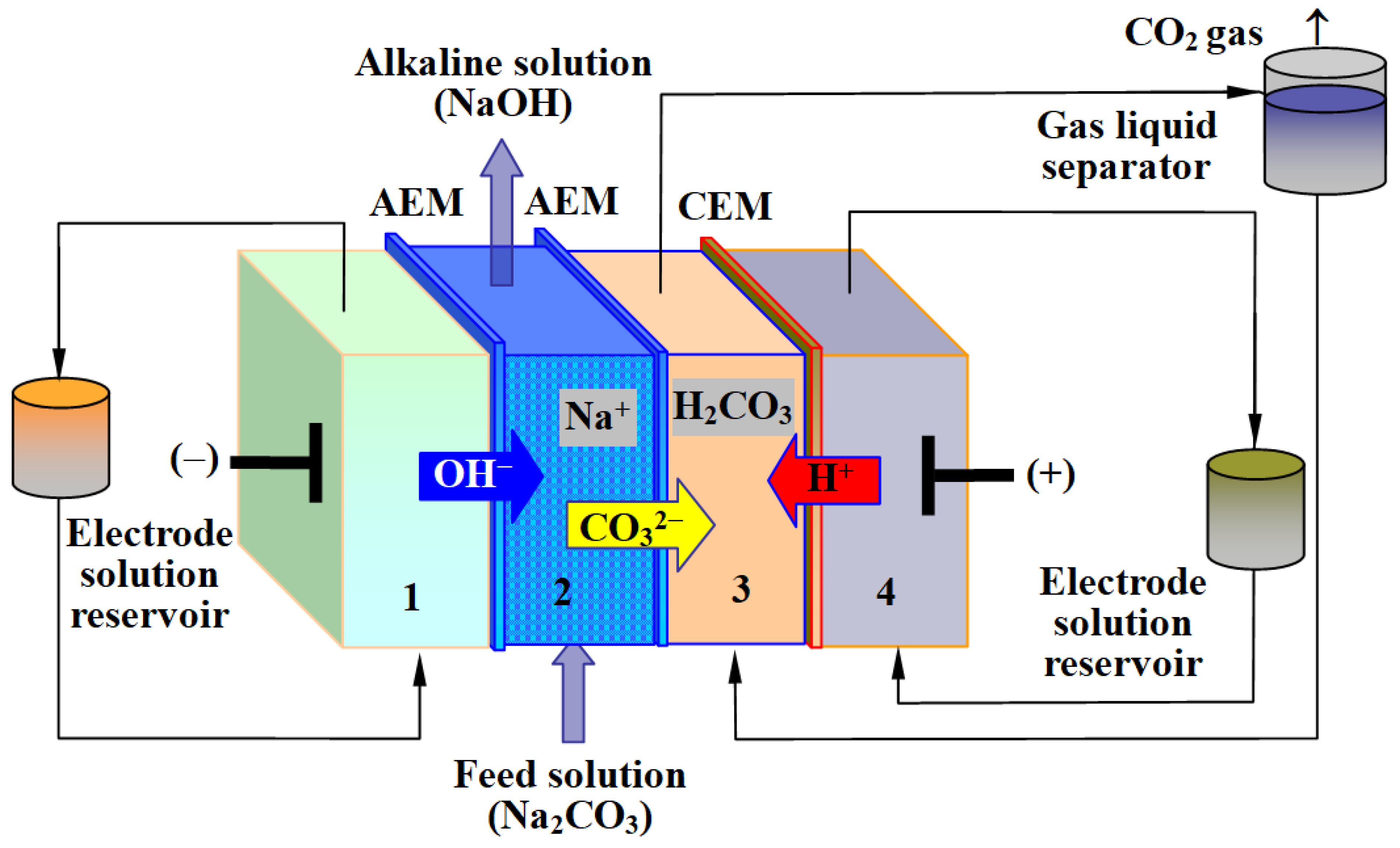
As previously mentioned, EDI technology concentrates ionic substances on ion exchange resins through selective permeation of membranes under the action of an electric field, extracting the increased concentration of substances for useful recycling while also extracting purified water. In fact, EDI can also extract gaseous substances, such as CO2. Y. Yang et al. designed and fabricated EDI (see Figure 6) as a novel electrochemical decarbonizing and ingathering technology, successfully recovering carbon dioxide gas by concentrating carbonates [76].
In the study, an “electro-dynamic inspissation (similarly abbreviated as EDI)” system was introduced to examine the ability of carbonate ions retrieval from a sodium carbonate solution. The ion exchange resin was added to serve as a conductor in the EDI device provides a new way to enable CO2 recovery from the concentrated stream and thus, a purified CO2 stream was obtained. The properties of the EDI system were in detail characterized, addressing its recovery effectiveness and providing a cost evaluation. The results demonstrated that EDI performs extremely well, with the current efficiency reaching 75% and the energy consumption calculated as 1.41 MJ kg−1 of CO2 captured. This system is an alternative and superior to most traditional technologies, such as amine absorption/thermal desorption. They cleverly used an electrochemical decarbonizing and ingathering method that exhibits the ability to segregate targeted ions absorbed in a dilute solution. They have successfully overcome the problem of electrical resistance because of the low conductivity of the dilute solution, in which a great part of the energy was consumed, and solved attempts at the low-cost CO2 recovery and sequestration that people have been pursuing for many years.

3.3. Remediation Strategies for Ammonia Recovery as Pure Fuel for Direct Ammonia Fuel Cells

Previous works of the electrodeionization have been focused on the removal of salts to purify water instead of retrieval of those salts as resources. All the researches provide evidence for the ability of this technology to retrieve useful ions and purify the water simultaneously [77,78], thus this technology can be considered as a promising approach for the retrieval of ammonia in domestic and municipal wastes especially a landfill leachate containing higher concentration of ammonia. However, there still are some issues according to previous studies, e.g., the concentration of NH3-N in the concentrated solution was only 80~100 mg/L, not high enough to retrieve them. Herein, we made attempt to solve the problems mentioned above by employing the electrochemical deionizing and ingathering (EDI) method. First, we ameliorated the conventional EDI set-up, which had been in application of the metal ions recovery with no precipitation on the surface of the ion exchange membrane. Second, in order to increase the enrichment factor, and to improve the utilization of electrical energy, a multi-stage EDI process was adopted in this work. After enrichment of 3-stages EDI process, a 3 orders magnitude of NH3-N from mg/L ingathered to be as g/L has been achieved to identify the possibility and applicability of ammonia retrieval. As it noticed that ammonia as energy and hydrogen carrier (17.6 w/w% hydrogen) has become a hot research topic in recent years [79]. This technology provides an alternative option for energy retrieval from a waste.
With the popularity of ammonia fuel cell, nitrogen-containing compounds are becoming an alternative energy sources. However, most of those nitrogen-containing compounds, especially ammonia, are often dispersed in domestic wastewater, and previous technologies for treating them typically require a large amount of energy. Therefore, the nitrogen retrieval from wastewater is becoming urgently needed of development. Adopting a new five-compartment electrodeionization technology, it has been demonstrated feasible to concentrate ammonia nitrogen in synthetic wastewater. The result indicates that the optimum current is 0.18 A in artificial domestic sewage with low concentration ammonium ions among 15 mg/L. The nitrogen concentration can be enriched for about 12 times in single stage. The removal rate of nitrogen can reach over 90% with energy consumption of 19.104 g/kW·h. It explores the feasibility to recover the ammonia in wastewater [80].
The use of an electrochemical deionizing and ingathering (EDI) method exhibits the ability to segregate targeted ions absorbed in a dilute solution. Through multistage experiment [81], we demonstrated a concentration of NH4+ of 836.3 mg/L and 1734.8 mg/L, 1032 and 953 times of magnitude respectively in the multistage process. Besides, we analyzed the possibility of separation of these ions by increasing applied voltage. This technology provides a feasibility of retrieving ammonia from a very low concentration in wastewater to a level which can be used as energy resources.
Previous studies on electrodeionization have mainly focused on how to concentrate ammonia and recover it in the form of ammonium salts. However, these studies have significant drawbacks: 1. Other metal ions are concentrated together for example, resulting in a very high concentration of impurity ions in the concentrate; 2. The concentration of ammonium salts is not high enough.
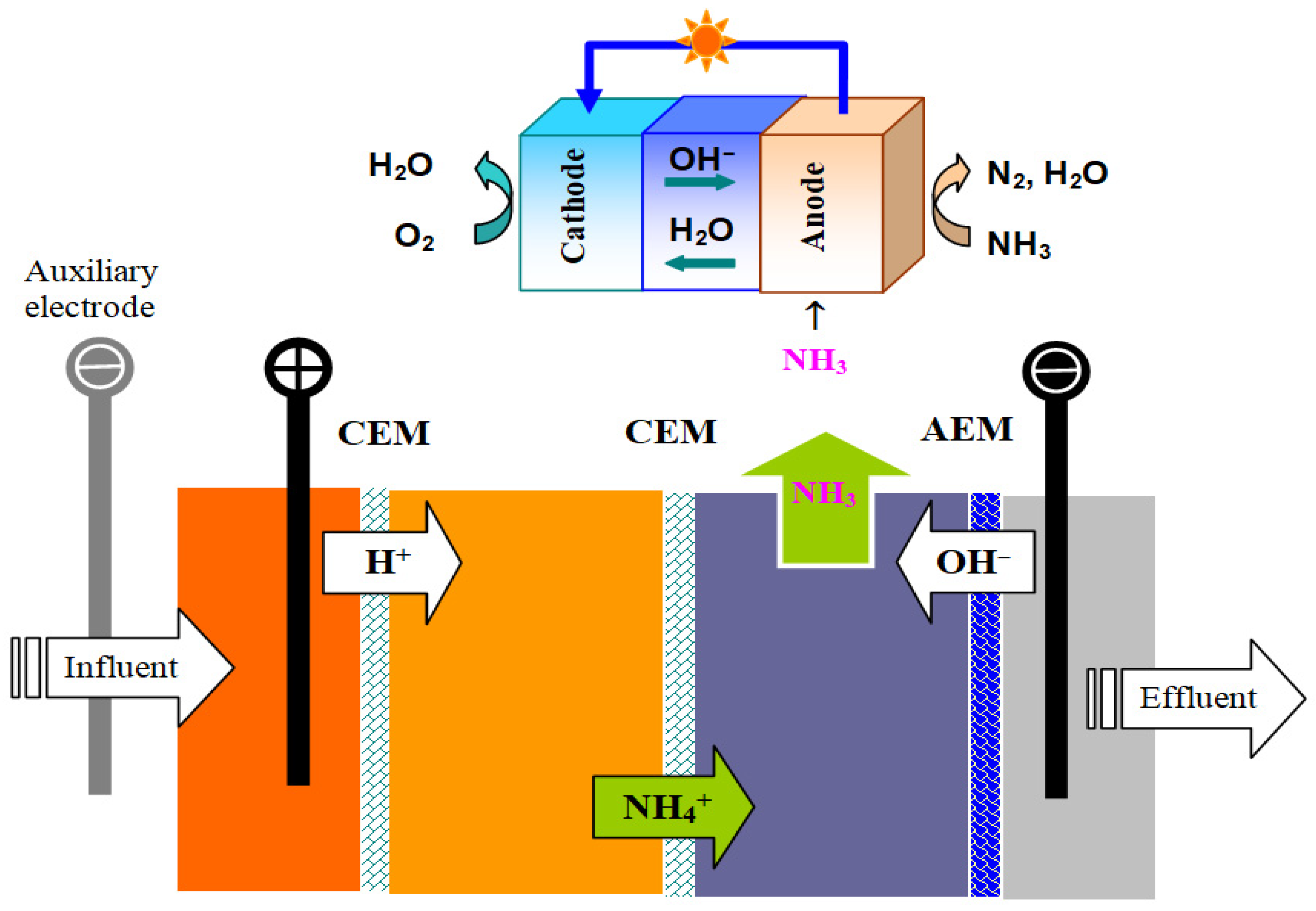
Given the high alkalinity of the cathode chamber, ammonium salts can be released as ammonia gas at pH value greater than 9, which facilitates the purification of ammonium salts. Based on the characteristic that ammonium salts easily volatilize into the air in alkaline solutions, a recovery strategy was developed as shown in Figure 7 (lower part). This strategy involves in collecting the released ammonia gas above the cathode chamber after the ammonium ions migrate to the alkaline region of the cathode. The distinct advantage of this strategy is that only ammonia is collected as a high-concentration single component, while other ions remain in the solution, thus effectively separating and concentrating the target ammonium ions.

3.4. The Combination of EDI Technology and PRB System

The reformative electrodeionization technology was shown to be a useful tool as a newly designed permeable reactive barrier system in this study [82]. In the PRB, ion exchange resins was employed as adsorption and denitrification media under the action of electric field, which can break water forming dissolved oxygen, H+ and OH ions simultaneously on anode and cathode respectively. H+ and NH4+ were selectively migrated through the cation exchange membrane (CEM) towards cathode zone. While the OH ions formed on cathode pass through the anion exchange membrane (AEM) to create alkaline circumstance, in which NH4+ become NH3 gas released and isolated (see Figure 7).
NH3 gas released from the cathode zone will be much high pure and that could be fed into a direct ammonia fuel cell to generate electricity for the recovery of energy. When the electricity was produced, it can be fed back to the PRB system to the next step of NH3 gas production for its continuous operation. Owing to high purity of NH3 gas for the generation of electricity, the direct ammonia fuel cell will have a long service life, eliminating concerns about catalyst failure.
It has been widely noticed that under the action of electric field, water can also be split to form dissolved oxygen on anode, which can oxidize some reductants such as ammonia. Ions like NH4+ can be accumulated and then oxidized to NO3 in the concentrated compartment, and the NO3 produced together with NH4+ could be biologically denitrified if the solution is suitable for microbial growth [48]. For obtaining a high standard effluent, the multistage operation of the PRB device was adopted satisfactory accumulation and denirification performance were presented. Previous experimental results show a promising application prospect of the system in treating groundwater pollution.
Obviously, some coexisting ions, such as calcium and magnesium, will migrate to the cathode electrode zone along with H+ and NH3 and precipitate there, which significantly affects the efficiency of ammonia separation. One way to solve this problem is to add an auxiliary cathode electrode before the solution enters the anode zone. Based on the alkaline characteristics formed at this cathode electrode, calcium and magnesium ions will precipitate first in this alkaline media, therefore, reducing the interferences.

4. Direct Ammonia Fuel Cells [83]

4.1. Direct Ammonia Solid Oxide Fuel Cells, SOFCs

Solid oxide fuel cells (SOFCs) are a relatively mature ammonia fuel cell technology and are considered one of the most efficient methods of power generation [84,85]. This type of fuel cell has demonstrated high energy conversion efficiency and high fuel flexibility [86,87]. During operation, the input ammonia gas is first cracked in a temperature range of 400 to 900 °C. The advantage of using such high temperatures is that it combines the ammonia cracking and power generation processes, thereby improving efficiency. At the SOFC anode, ammonia gas can be directly introduced without any pretreatment. High temperatures also reduce the cost and requirements of a separate ammonia cracking unit and increase ionic conductivity, thus minimizing ohmic losses in the electrolyte [88,89,90]. First direct ammonia-fueled SOFC was designed early as 1980 to generate electricity while simultaneously collecting NO as a chemical feedstock, similar denitrifications of flue gas. This fuel cell consisted of an Y2O3-stabilized ZrO2 (YSZ) electrolyte and Pt electrodes. The electrochemical reactions occurring at the anode are as follows:
2NH3 + 5O2 → 2NO + 3H2O + 10e
2NH3 + 3NO → 5/2N2 + 3H2O
Due to the diffusion rate of oxygen anions through the electrolyte is relatively slow, Equation (10) becomes the rate-determining step. The simultaneous production of NO in the above experiment is undesirable, as shown in Equation (11). Therefore, the development of SOFC technology has shifted towards using N2 as the sole nitrogen-containing compound. Based on the type of electrolyte used, SOFCs can be divided into two categories: SOFCs based on oxygen anion-conducting electrolytes (SOFC-O) and SOFCs based on proton-conducting electrolytes (SOFC-H) [89,90].
The working principle of ammonia-fueled SOFC-O is based on the transport of oxygen anions in the electrolyte. The oxidation of ammonia involves two steps. The first step is the cracking of ammonia, followed by the electrochemical oxidation of the resulting hydrogen. Oxygen or air is introduced into the cathode chamber and reduced to oxygen anions at the cathode-electrolyte interface. These oxygen ions pass through the electrolyte and react with hydrogen at the anode to produce water. The reactions occurring at the anode and cathode are shown below, and Equations (9) and (10) describe the reaction process.
Anode: H2 +O2− ⟶ H2O + 2e
Cathode: 1/2O2 +2e ⟶ O2
Besides O2− ionic conductors, oxides with proton conduction such as doped BaCeO3 and BaZrO3 can also be used as the electrolytes for direct ammonia SOFCs.

4.2. Alkaline Membrane Direct Ammonia Fuel Cell, DAFC

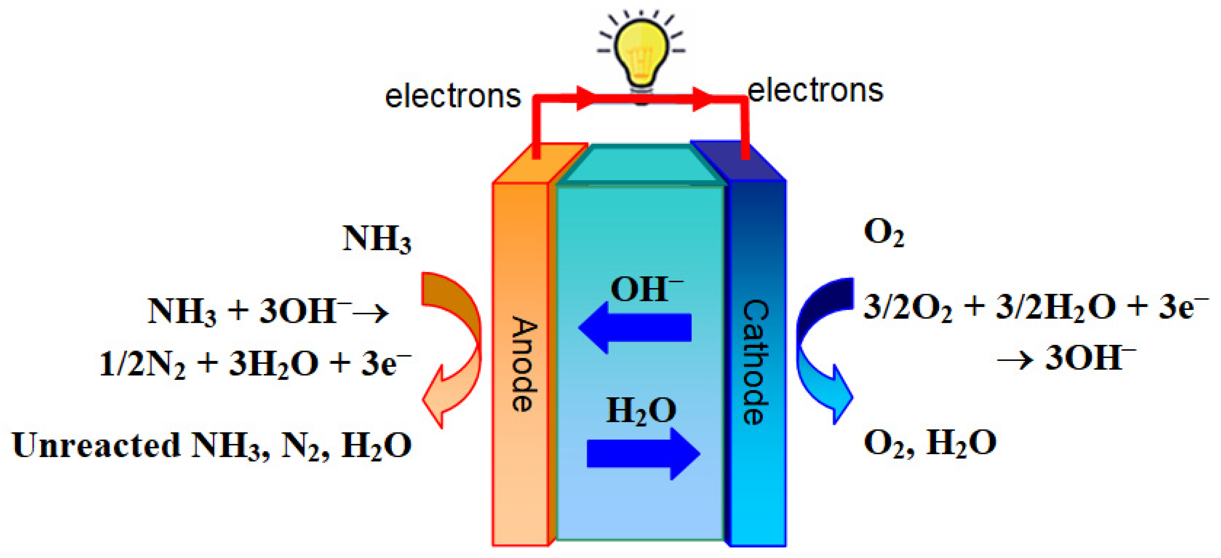
The working principle of aqueous direct ammonia fuel cells is similar to that of solid oxide fuel cells (SOFCs), but the difference is that instead of transporting oxygen anions through the electrolyte, it transports hydroxide ions (OH) in an aqueous solution through the electrolyte. Most direct ammonia fuel cells based on alkaline membrane fuel cells (AMFCs) operate in the low-temperature range of approximately 50–120 °C.
Oxygen or air is introduced into the cathode compartment and reacts with water to produce hydroxide ions (OH). These hydroxide ions are then transported through the alkaline membrane to the anode side, where they react with ammonia to produce nitrogen and water. The Tao group reported the first low-temperature direct ammonia fuel cell based on an alkaline exchange membrane (AEM) or acidic cation exchange membrane (CEM), which uses a Nafion membrane as the electrolyte [91,92]. When an alkaline membrane is used as the electrolyte, the reactions occurring at the anode and cathode are as shown below, and a schematic diagram is shown in Figure 8. Significant progress has been made on alkaline membrane DAFCs with a power density of 853 mW cm−2 has been achieved at 60 °C and a DAFC stack of 75W has been demonstrated too [93,94]. Precious metal catalysts were used to achieve high power density. To reduce the cost, it is desired to develop non-precious metal catalysts for ammonia oxidation reaction (AOR) to be used as anode for DAFCs [95,96,97,98,99,100,101].

4.3. Near Ambient Temperature Direct Ammonia Solid Oxide Fuel Cells

One of the key challenges for low temperature fuel cells with liquid fuels such as ammonia or methanol solution, the fuel cross-over from the anode to the cathode caused increased over-potential, loss of fuels and decreased efficiency. To solve this problem, it is better replace the polymeric membrane by dense ceramic thin film. In 2024, Tao’s group reported that some oxides such as SrZr0.8Y0.2O3−δ, SrCe0.8Y0.2O3−δ exhibit high mixed OH/H+ ionic conductivity in water, which have been demonstrated as electrolyte for direct ammonia fuel cells [102,103]. To differentiate this new type of fuel cells from conventional solid oxide fuel cells with operating temperature above 400 °C, it is called near ambient temperature solid oxide fuel cells (NAT-SOFCs). Most of the fuels for SOFCs can be used as fuels for NAT-SOFCs while the durability is expected to be better due to significantly reduced operating temperature, typically below 300 °C.

4.4. Catalysts for Direct Ammonia Fuel Cells

Selecting an anode catalyst with high selectivity for nitrogen (i.e., where nitrogen is the only nitrogen-containing product) is crucial. Numerous studies have shown that the reaction rate is significantly increased in the presence of nickel-based catalysts [104]. Furthermore, it also improves selectivity and lowers the reaction temperature. Highly efficient nickel-based anode catalysts doped with cerium oxide [105] can further enhance efficiency [106,107].
Impregnating high-performance anode based on La0.55Sr0.30TiO3−δ coupled NiCo alloy nanoparticles scaffold results in an excellent anode material [108] those Nickel-based alloys are potentially important for direct ammonia-fueled SOFCs [109,110,111]. Perovskite oxides tend to be chosen for this reason [112].
Since the cathode is dependent on the oxygen reduction reaction, cathodes used in ammonia SOFCs can be the same material as those in SOFCs fueled with other fuels such as hydrogen, methane and other hydrocarbons [113,114]. A cermet with excellent catalytic activity of Ni–BaCe0.4Zr0.4Y0.2O3−δ completely decomposed ammonia at around 600 °C [115], in Tao’s group they achieved temperature significantly reduced below 300 °C [103]. This achievement is a milestone that will enable direct fuel cells to enter the practical application stage, and the technology is already protected by patents in Europe, Japan, China, and the United States (US12421130B2).
The catalysts for ammonia fuel cells, which use ammonia as fuel, have attracted considerable attention because understanding the mechanism of the ammonia electro-oxidation reaction (AOR) is crucial for analyzing AOR activity [116]. Notably, the structure and temperature of the catalyst have a significant impact on the ammonia oxidation rate and selectivity [117].
Both platinum-based and nickel-based materials are active catalysts for the ammonia oxidation reaction (AOR), and have been extensively studied in numerous publications [118,119,120,121]. The reaction mechanism of nickel-based materials in alkaline solutions involves the formation of a protective Ni(OH)2 layer, which can be converted to NiOOH through redox reactions. The NiOOH species is responsible for ammonia oxidation and its catalytic activity [122]. Although some studies have proposed a direct electron transfer mechanism between ammonia and NiOOH, the AOR reaction may proceed through an indirect electron transfer mechanism, where ammonia is oxidized while NiOOH is reduced to Ni(OH)2 on the nickel nanoparticle structure [123]. Furthermore, other studies have reported the formation of alloyed metal species, such as active Ni2P supported on nickel foam [124,125]

4.5. In-Situ Preparation of H2O2 from Air for Aqueous Direct Fuel Cells

Aqueous direct fuel cells usually use oxygen as the oxidant and the platinum catalysts as the cathode catalyst. In our previous research, O2 even air can in situ produce H2O2 under the action of Pd catalyst [126]. In this experiment, we developed a unique direct urea fuel cell as example, which used H2O2 as the oxidant and Pd/C as the cathode catalyst. The results demonstrate that when H2O2 served as the oxidant, the open circuit voltage and maximum power density of the fuel cell are much higher than those of urea fuel cell with O2 as the oxidant. Therefore, if O2 or air can be in situ converted to H2O2, the performance of the fuel cell can be greatly improved.
Catalyst of Pd worked in in-situ H2O2 generation was originally developed for Fenton-like reactions [127]. In the reaction, Fe species worked in decompose H2O2 to degrade organic pollutants. When applying this catalyst for Fenton-like reaction with addition of H2O2, it was also found that Pd and PdO played important roles and the synergistic effect between Fe and Pd species actually existed in dye removal. The unique nanostructure makes the catalyst to be a novel and welcoming choice for H2O2 favorite reactions.

5. Conclusions and Perspective

5.1. Conclusions

The inherent characteristics of ZVI and the reactions and transformations it undergoes in groundwater, including ZVI corrosion, aggregation, mineral precipitation, and environmental impacts, present certain limitations to the remediation of chlorinated hydrocarbon contamination using ZVI-PRB. Therefore, emerging surface-modified nZVI materials, due to their high specific surface area and reduction rate, have become a substitute for traditional single ZVI-PRB materials in recent years. Furthermore, the development of core-shell materials [128] and in-situ reaction zone technologies can address problems such as ZVI aggregation and poor long-term reaction performance. However, as is well known, the high cost of ZVI materials and their limited ability to remediate only halogenated hydrocarbon contamination are significant factors hindering their large-scale application.
During the operation of ZVI-PRB, four factors significantly affect its performance in remediating chlorinated hydrocarbons in groundwater: groundwater chemical composition, microorganisms, temperature, and coexisting organic substances. Groundwater chemical composition has been extensively studied, and increases in pH, dissolved oxygen (DO), nitrate (NO3), and sulfate (SO42−) all significantly reduce the reactivity of ZVI-PRB, making them important parameters for controlling the lifespan of the PRB. Microorganisms can effectively utilize excess molecular hydrogen, promote electron transfer, and reduce toxicity, but maintaining biological activity and optimizing electron selection and transfer processes remain significant challenges.
Temperature effects have been one of the research hotspots in recent years. When the temperature increases from 25 °C to 40 °C, the reduction performance of ZVI-PRB can be enhanced several times. Addressing the supply and distribution of heat is one of the key research areas for practical applications. Depending on the type of organic matter, the effects of various coexisting organic substances on ZVI-PRB performance vary. The presence of natural organic matter can reduce the performance and lifespan of ZVI-PRB.
Natural organic matter, including nitrogen-containing compounds, contains a large amount of hydrogen, and ZVI-PRB is ineffective in its remediation. Electrochemical in-situ remediation provides a solution by generating dissolved oxygen and other oxidative active substances in situ, effectively removing organic matter, including nitrogen-containing compounds. The combination of electrochemically generated active oxidants and microbial remediation offers a new approach to remediation, fully utilizing microorganisms to absorb organic carbon and nitrogen compounds as nutrients, while electrochemistry provides oxygen or hydrogen, forming a closed loop. This represents a novel pathway.
Electrochemical methods require a power supply, which adds a certain degree of complexity to field operations. However, this external power source can utilize renewable energy sources such as solar and wind power, solving the power supply problem on-site and providing a complete remediation system for bio-electrochemical-PRB.
Fortunately, the development of fuel cells provides another new PRB technology: in-situ power generation without the need for an external power supply. This utilizes electrochemical characteristics to remediate organic matter including nitrogen-containing compounds in PRB. This facilitates comprehensive PRB remediation, not only for halogenated hydrocarbons but also for inorganic pollutants such as ammonia.

5.2. Perspective

In-situ power generation-electrochemical-PRB is a promising remediation method. However, the current research is limited and a further in-depth research from theory to practice is needed. The main challenge lies in practical application, as it is well known that the composition of groundwater varies depending on the specific site environment. Compared to conventional EDI devices for PRBs and direct fuel cell for power generation, the electrolyte content in the water to be treated is usually significantly lower. When the electrolyte concentration is low, it directly hinders the electrochemical reaction of the system, such as hindering ion transport. A decrease in electrolyte concentration leads to a reduction in the number of ions in the electrolyte, decreasing the migration rate of ions between the electrodes, thus increasing internal resistance, and reducing both energy density and cycle life.
Methods to improve low-concentration electrolytes include adding solid electrolytes to form a stable solid electrolyte interface, strengthening the reaction interface, and further improving efficiency. Another method is the EDI-PRB technology proposed in this paper, which is based on EDI’s ability to accumulate ions in the solution by using ion exchange resins, thereby increasing the electrolyte concentration.
Obviously, pH is a key factor affecting ammonia nitrogen removal rate and voltage output, and many researchers have pointed out the need to optimize it to achieve the best power generation effect. pH value affects the rate of electrochemical reactions, as well as the potential and power generation. For the remediation of specific pollutants, researchers determine the optimal operating conditions by measuring the relationship between potential and pH, known as Pourbaix diagram. The potential-pH diagram, which is an electrochemical equilibrium diagram showing the relationship between the system’s electrode potential and pH value, accurately provides a phase diagram at phase equilibrium.
Under alkaline conditions, the solubility and electrochemical activity of ammonia are usually higher because NH3 is more easily oxidized at the anode than NH4+. Acidic environments may inhibit ammonia oxidation, but some catalysts perform better at neutral condition. In addition, alkaline electrolytes are widely used due to their high ionic conductivity and low mass transfer resistance, which indirectly supports the regulatory role of pH on power generation efficiency.
In EDI-PRB, the embedded ion exchange resin plays a crucial role. In online EDI-PRB systems, the presence of ion exchange resin significantly increases electrolyte concentration and conductivity, thereby reducing energy consumption and improving efficiency. Therefore, the selection of ion exchange resins, including natural ion exchangers, is of great importance, and further research in this area is needed.
The microelectrolysis-microbial-PRB method is also quite noteworthy and worthy of in-depth research. The microelectrolysis-microbial method is a combined treatment technology that integrates microelectrolysis technology with microbial treatment processes for the efficient degradation of recalcitrant organic pollutants. This method typically uses microelectrolysis as a pretreatment unit to improve biodegradability through electrochemical reactions, followed by the use of microbial metabolism to achieve complete degradation of organic matter, and can be used for groundwater remediation.
The microbial treatment unit usually employs anaerobic or aerobic biological processes, utilizing microbial communities to convert biodegradable organic matter into carbon dioxide, water, and biomass. For nitrogen-containing pollutants, it can convert them into N2. In the combined process, microelectrolysis pretreatment provides electron donors, enhancing the efficiency of microbial utilization of substrates. The hydrogen produced by electrolysis also provides metabolic substances for the biological process.
The redox fuel cells, such as direct ammonia or urea fuel cells, combine wastewater treatment and electricity generation together, which is very promising research direction. Instead of consuming energy for wastewater treatment, valuable electricity is generated, as a bonus. Undoubtedly, the multi-stage EDI, membrane resistance, pumping, and gas collection are likely to consume energy, and the energy required for these processes has not yet been thoroughly determined. The balance between net energy recovery [129,130] and consumption still needs further investigation to make new PRBs practical.
In addition to the methods described in this paper, there are many literatures on how to design direct ammonia fuel cells [129,130]. As for the comparison with more literature, including the electricity generation of nitrogen-containing compounds and possible intermediate by-products in chemical reaction processes, such as nitrate, nitrite, NO, N2O, there are still many controversies, but it does not affect the fact that efficient electricity generation or hydrogen production can be achieved [131,132]. For an ammonia fuel cell, if the products are value-added nitrites and nitrates, then it will be a co-generation fuel cell which simultaneously generate electricity and valuable chemicals, which would be an ideal option. Cogeneration ammonia fuel cells will be a new exciting research area.

Author Contributions

Conceptualization, H.Z.; Methodology, X.F.; Software & Validation, D.Y.; Investigation, Y.K. and D.Y.; Resources, Y.K.; Writing—original draft, H.Z. and X.F.; Writing—review & editing, Z.W. and S.T.; Supervision, Z.W. and S.T. All authors have read and agreed to the published version of the manuscript.

Funding

This research received no external funding.

Data Availability Statement

The original contributions presented in this study are included in the article. Further inquiries can be directed to the corresponding authors.

Conflicts of Interest

The authors declare no conflict of interest.

References

  1. Scanlon, B.R.; Fakhreddine, S.; Rateb, A.; De Graaf, I.; Famiglietti, J.; Gleeson, T.; Grafton, R.Q.; Jobbagy, E.; Kebede, S.; Kolusu, S.R.; et al. Global Water Resources and the Role of Groundwater in a Resilient Water Future. Nat. Rev. Earth Environ. 2023, 4, 87–101. [Google Scholar] [CrossRef]
  2. Shaikh, M.; Birajdar, F. Groundwater and Ecosystems: Understanding the Critical Interplay for Sustainability and Conservation. EPRA Int. J. Multidiscip. Res. 2024, 10, 181–186. [Google Scholar] [CrossRef]
  3. Van Der Gun, J. Groundwater Resources Sustainability. In Global Groundwater; Elsevier: Amsterdam, The Netherlands, 2021; pp. 331–345. [Google Scholar]
  4. Kuang, X.; Liu, J.; Scanlon, B.R.; Jiao, J.J.; Jasechko, S.; Lancia, M.; Biskaborn, B.K.; Wada, Y.; Li, H.; Zeng, Z.; et al. The Changing Nature of Groundwater in the Global Water Cycle. Science 2024, 383, 6686. [Google Scholar] [CrossRef] [PubMed]
  5. Ullah, Z.; Rashid, A.; Ghani, J.; Nawab, J.; Zeng, X.-C.; Shah, M.; Alrefaei, A.F.; Kamel, M.; Aleya, L.; Abdel-Daim, M.M.; et al. Groundwater Contamination through Potentially Harmful Metals and Its Implications in Groundwater Management. Front. Environ. Sci. 2022, 10, 1021596. [Google Scholar] [CrossRef]
  6. Mukherjee, A.; Jha, M.K.; Kim, K.-W.; Pacheco, F.A.L. Groundwater Resources: Challenges and Future Opportunities. Sci. Rep. 2024, 14, 28540. [Google Scholar] [CrossRef]
  7. Brindha, K.; Schneider, M. Impact of Urbanization on Groundwater Quality. In GIS and Geostatistical Techniques for Groundwater Science; Elsevier: Amsterdam, The Netherlands, 2019; pp. 179–196. [Google Scholar]
  8. Mishra, R.K. Fresh Water Availability and Its Global Challenge. Br. J. Multidiscip. Adv. Stud. 2023, 4, 1–78. [Google Scholar] [CrossRef]
  9. Luijendijk, E.; Gleeson, T.; Moosdorf, N. Fresh Groundwater Discharge Insignificant for the World’s Oceans but Important for Coastal Ecosystems. Nat. Commun. 2020, 11, 1260. [Google Scholar] [CrossRef]
  10. Elshall, A.S.; Arik, A.D.; El-Kadi, A.I.; Pierce, S.; Ye, M.; Burnett, K.M.; Wada, C.A.; Bremer, L.L.; Chun, G. Groundwater Sustainability: A Review of the Interactions between Science and Policy. Environ. Res. Lett. 2020, 15, 093004. [Google Scholar] [CrossRef]
  11. An, D.; Xi, B.; Wang, Y.; Xu, D.; Tang, J.; Dong, L.; Ren, J.; Pang, C. A Sustainability Assessment Methodology for Prioritizing the Technologies of Groundwater Contamination Remediation. J. Clean. Prod. 2016, 112, 4647–4656. [Google Scholar] [CrossRef]
  12. Zhang, S.; Mao, G.; Crittenden, J.; Liu, X.; Du, H. Groundwater Remediation from the Past to the Future: A Bibliometric Analysis. Water Res. 2017, 119, 114–125. [Google Scholar] [CrossRef]
  13. An, D.; Xi, B.; Ren, J.; Wang, Y.; Jia, X.; He, C.; Li, Z. Sustainability Assessment of Groundwater Remediation Technologies Based on Multi-Criteria Decision Making Method. Resour. Conserv. Recycl. 2017, 119, 36–46. [Google Scholar] [CrossRef]
  14. Pradhan, B.; Chand, S.; Chand, S.; Rout, P.R.; Naik, S.K. Emerging Groundwater Contaminants: A Comprehensive Review on Their Health Hazards and Remediation Technologies. Groundw. Sustain. Dev. 2023, 20, 100868. [Google Scholar] [CrossRef]
  15. Alazaiza, M.Y.D.; Albahnasawi, A.; Ali, G.A.M.; Bashir, M.J.K.; Copty, N.K.; Amr, S.S.A.; Abushammala, M.F.M.; Al Maskari, T. Recent Advances of Nanoremediation Technologies for Soil and Groundwater Remediation: A Review. Water 2021, 13, 2186. [Google Scholar] [CrossRef]
  16. Tack, F.M.G.; Bardos, P. Overview of Soil and Groundwater Remediation. In Soil and Groundwater Remediation Technologies; Ok, Y.S., Rinklebe, J., Hou, D., Tsang, D.C.W., Tack, F.M.G., Eds.; CRC Press: Boca Raton, FL, USA, 2020; pp. 1–11. [Google Scholar]
  17. Tatti, F.; Petrangeli Papini, M.; Torretta, V.; Mancini, G.; Boni, M.R.; Viotti, P. Experimental and Numerical Evaluation of Groundwater Circulation Wells as a Remediation Technology for Persistent, Low Permeability Contaminant Source Zones. J. Contam. Hydrol. 2019, 222, 89–100. [Google Scholar] [CrossRef]
  18. Brusseau, M.L. Soil and Groundwater Remediation. In Environmental and Pollution Science; Elsevier: Amsterdam, The Netherlands, 2019; pp. 329–354. [Google Scholar]
  19. Thomé, A.; Reddy, K.R.; Reginatto, C.; Cecchin, I. Review of Nanotechnology for Soil and Groundwater Remediation: Brazilian Perspectives. Water Air Soil Pollut. 2015, 226, 121. [Google Scholar] [CrossRef]
  20. Faisal, A.A.H.; Sulaymon, A.H.; Khaliefa, Q.M. A Review of Permeable Reactive Barrier as Passive Sustainable Technology for Groundwater Remediation. Int. J. Environ. Sci. Technol. 2018, 15, 1123–1138. [Google Scholar] [CrossRef]
  21. Zhou, Y.; Chen, L.; Wang, J.; Lu, L.; Liu, F.; Chen, C.; Qin, X. Solution, Exchangeable and Fixed Ammonium in Natural Diatomite as a Simulated PRB Material: Effects of Adsorption and Bioregeneration Processes. Environ. Sci. Pollut. Res. 2023, 30, 52433–52445. [Google Scholar] [CrossRef]
  22. Lawrinenko, M.; Rhea, L.; Forshay, K.J.; Lee, T.R.; White, M.; Wilkin, R.T. Long-Term Field Study of Nitrate and Ammonium Remediation Using a Permeable Reactive Barrier at a Livestock Feeding Operation. J. Environ. Manag. 2025, 380, 124962. [Google Scholar] [CrossRef] [PubMed]
  23. Mayacela-Rojas, C.M.; Molinari, A.; Cortina, J.L.; Gibert, O.; Ayora, C.; Tavolaro, A.; Rivera-Velásquez, M.F.; Fallico, C. Removal of Transition Metals from Contaminated Aquifers by PRB Technology: Performance Comparison among Reactive Materials. Int. J. Environ. Res. Public Health 2021, 18, 6075. [Google Scholar] [CrossRef] [PubMed]
  24. Zhan, L.; Zhao, L.; Wu, L.; You, Y.; Bate, B. A Passive Sink-Zeolite Permeable Reactive Barrier to Control NH4+-N Pollution Plume within Groundwater: Conceptual Design and Numerical Modeling. Chemosphere 2023, 334, 138965. [Google Scholar] [CrossRef] [PubMed]
  25. Bilardi, S.; Calabrò, P.S.; Moraci, N. A Review of the Hydraulic Performance of Permeable Reactive Barriers Based on Granular Zero Valent Iron. Water 2023, 15, 200. [Google Scholar] [CrossRef]
  26. Budania, R.; Dangayach, S. A Comprehensive Review on Permeable Reactive Barrier for the Remediation of Groundwater Contamination. J. Environ. Manag. 2023, 332, 117343. [Google Scholar] [CrossRef] [PubMed]
  27. Andrade, D.C.; Dos Santos, E.V. Combination of Electrokinetic Remediation with Permeable Reactive Barriers to Remove Organic Compounds from Soils. Curr. Opin. Electrochem. 2020, 22, 136–144. [Google Scholar] [CrossRef]
  28. O’Hannesin, S.; Gillham, R. In Situ Degradation of Halogenated Organics by Permeable Reaction Wall. Ground Water Curr. 1993, 69, 1–5. [Google Scholar]
  29. Fu, F.; Dionysiou, D.D.; Liu, H. The Use of Zero-Valent Iron for Groundwater Remediation and Wastewater Treatment: A Review. J. Hazard. Mater. 2014, 267, 194–205. [Google Scholar] [CrossRef]
  30. Weber, A.; Ruhl, A.S.; Amos, R.T. Investigating Dominant Processes in ZVI Permeable Reactive Barriers Using Reactive Transport Modeling. J. Contam. Hydrol. 2013, 151, 68–82. [Google Scholar] [CrossRef] [PubMed]
  31. Henderson, A.D.; Demond, A.H. Long-Term Performance of Zero-Valent Iron Permeable Reactive Barriers: A Critical Review. Environ. Eng. Sci. 2007, 24, 401–423. [Google Scholar] [CrossRef]
  32. Sun, Y.; Li, J.; Huang, T.; Guan, X. The Influences of Iron Characteristics, Operating Conditions and Solution Chemistry on Contaminants Removal by Zero-Valent Iron: A Review. Water Res. 2016, 100, 277–295. [Google Scholar] [CrossRef] [PubMed]
  33. Lawrinenko, M.; Kurwadkar, S.; Wilkin, R.T. Long-Term Performance Evaluation of Zero-Valent Iron Amended Permeable Reactive Barriers for Groundwater Remediation—A Mechanistic Approach. Geosci. Front. 2023, 14, 101494. [Google Scholar] [CrossRef]
  34. Wang, X.; Xin, J.; Yuan, M.; Zhao, F. Electron Competition and Electron Selectivity in Abiotic, Biotic, and Coupled Systems for Dechlorinating Chlorinated Aliphatic Hydrocarbons in Groundwater: A Review. Water Res. 2020, 183, 116060. [Google Scholar] [CrossRef]
  35. VanStone, N.; Przepiora, A.; Vogan, J.; Lacrampe-Couloume, G.; Powers, B.; Perez, E.; Mabury, S.; Sherwood Lollar, B. Monitoring Trichloroethene Remediation at an Iron Permeable Reactive Barrier Using Stable Carbon Isotopic Analysis. J. Contam. Hydrol. 2005, 78, 313–325. [Google Scholar] [CrossRef] [PubMed]
  36. Song, T.; Gao, Y. Removal of Trichloroethylene (TCE) from Groundwater by GAC and ZVI. Desalination Water Treat. 2014, 52, 5990–5994. [Google Scholar] [CrossRef]
  37. Wei, Z.; Seo, Y. Trichloroethylene (TCE) Adsorption Using Sustainable Organic Mulch. J. Hazard. Mater. 2010, 181, 147–153. [Google Scholar] [CrossRef]
  38. Baric, M.; Pierro, L.; Pietrangeli, B.; Papini, M.P. Polyhydroxyalkanoate (PHB) as a Slow-Release Electron Donor for Advanced in Situ Bioremediation of Chlorinated Solvent-Contaminated Aquifers. New Biotechnol. 2014, 31, 377–382. [Google Scholar] [CrossRef]
  39. Grajales-Mesa, S.J.; Malina, G. Pilot-Scale Evaluation of a Permeable Reactive Barrier with Compost and Brown Coal to Treat Groundwater Contaminated with Trichloroethylene. Water 2019, 11, 1922. [Google Scholar] [CrossRef]
  40. Velimirovic, M.; Tosco, T.; Uyttebroek, M.; Luna, M.; Gastone, F.; De Boer, C.; Klaas, N.; Sapion, H.; Eisenmann, H.; Larsson, P.-O.; et al. Field Assessment of Guar Gum Stabilized Microscale Zerovalent Iron Particles for In-Situ Remediation of 1,1,1-Trichloroethane. J. Contam. Hydrol. 2014, 164, 88–99. [Google Scholar] [CrossRef]
  41. Galogahi, F.M.; Zhu, Y.; An, H.; Nguyen, N.-T. Core-Shell Microparticles: Generation Approaches and Applications. J. Sci. Adv. Mater. Devices 2020, 5, 417–435. [Google Scholar] [CrossRef]
  42. Zheng, T.; Zhan, J.; He, J.; Day, C.; Lu, Y.; McPherson, G.L.; Piringer, G.; John, V.T. Reactivity Characteristics of Nanoscale Zerovalent Iron−Silica Composites for Trichloroethylene Remediation. Environ. Sci. Technol. 2008, 42, 4494–4499. [Google Scholar] [CrossRef] [PubMed]
  43. Wang, S.; Han, Y.; Cao, X.; Zhao, D.; Yang, D.; Chen, J. Enhanced Degradation of Trichloroethylene Using Bentonite-Supported Nanoscale Fe/Ni and Humic Acids. Environ. Chem. Lett. 2016, 14, 237–242. [Google Scholar] [CrossRef]
  44. Baldermann, A.; Kaufhold, S.; Dohrmann, R.; Baldermann, C.; Letofsky-Papst, I.; Dietzel, M. A Novel nZVI–Bentonite Nanocomposite to Remove Trichloroethene (TCE) from Solution. Chemosphere 2021, 282, 131018. [Google Scholar] [CrossRef]
  45. Lawrinenko, M.; Wang, Z.; Horton, R.; Mendivelso-Perez, D.; Smith, E.A.; Webster, T.E.; Laird, D.A.; Van Leeuwen, J.H. Macroporous Carbon Supported Zerovalent Iron for Remediation of Trichloroethylene. ACS Sustain. Chem. Eng. 2017, 5, 1586–1593. [Google Scholar] [CrossRef]
  46. Song, J.; Huang, G.; Han, D.; Hou, Q.; Gan, L.; Zhang, M. A Review of Reactive Media within Permeable Reactive Barriers for the Removal of Heavy Metal(Loid)s in Groundwater: Current Status and Future Prospects. J. Clean. Prod. 2021, 319, 128644. [Google Scholar] [CrossRef]
  47. Winter, M.; Brodd, R.J. What Are Batteries, Fuel Cells, and Supercapacitors? Chem. Rev. 2004, 104, 4245–4270. [Google Scholar] [CrossRef]
  48. Zhang, H.; Xu, W.; Feng, D.; Liu, Z.; Wu, Z. Self-Powered Denitration of Landfill Leachate through Ammonia/Nitrate Coupled Redox Fuel Cell Reactor. Bioresour. Technol. 2016, 203, 56–61. [Google Scholar] [CrossRef] [PubMed]
  49. Vaccari, M.; Vinti, G.; Tudor, T. An Analysis of the Risk Posed by Leachate from Dumpsites in Developing Countries. Environments 2018, 5, 99. [Google Scholar] [CrossRef]
  50. Yu, B.; Xu, W.; Yang, X.; Zhang, H.; Fan, Z.; Wu, Z. Self-powered Redox Fuel Cell as Feasible Permeable Reactive Barrier for the Removal of Phenol. In Proceedings of the 8th International Congress on Environmental Geotechnics Volume 1 ICEG 2018, Hangzhou, China, 28 October–1 November 2018; Zhan, L., Chen, Y., Bouazza, A., Eds.; Environmental Science and Engineering; Springer: Singapore, 2019; pp. 812–818. [Google Scholar] [CrossRef]
  51. Fseha, Y.H.; Shaheen, J.; Sizirici, B. Phenol Contaminated Municipal Wastewater Treatment Using Date Palm Frond Biochar: Optimization Using Response Surface Methodology. Emerg. Contam. 2023, 9, 100202. [Google Scholar] [CrossRef]
  52. Przydatek, G.; Kanownik, W. Impact of Small Municipal Solid Waste Landfill on Groundwater Quality. Environ. Monit. Assess. 2019, 191, 169. [Google Scholar] [CrossRef]
  53. Roy, W.R. Groundwater Contamination from Municipal Landfills in the USA. In Contamination of Groundwaters; Adriano, D.C., Iskandar, A.K., Murarka, I.P., Eds.; CRC Press: Boca Raton, FL, USA, 2020; pp. 411–446. [Google Scholar]
  54. Eryılmaz, C.; Genç, A. Review of Treatment Technologies for the Removal of Phenol from Wastewaters. J. Water Chem. Technol. 2021, 43, 145–154. [Google Scholar] [CrossRef]
  55. Mohanta, V.L.; Mishra, B.K. Occurrence and Fate of Phenolic Compounds in Groundwater and Their Associated Risks. In Legacy, Pathogenic and Emerging Contaminants in the Environment; CRC Press: London, UK, 2021; pp. 291–310. [Google Scholar]
  56. Abiriga, D.; Vestgarden, L.S.; Klempe, H. Groundwater Contamination from a Municipal Landfill: Effect of Age, Landfill Closure, and Season on Groundwater Chemistry. Sci. Total Environ. 2020, 737, 140307. [Google Scholar] [CrossRef]
  57. Samadder, S.R.; Prabhakar, R.; Khan, D.; Kishan, D.; Chauhan, M.S. Analysis of the Contaminants Released from Municipal Solid Waste Landfill Sit: A Case Study. Sci. Total Environ. 2017, 580, 593–601. [Google Scholar] [CrossRef]
  58. Vollprecht, D.; Bobe, C.; Stiegler, R.; Van De Vijver, E.; Wolfsberger, T.; Küppers, B.; Scholger, R. Relating Magnetic Properties of Municipal Solid Waste Constituents to Iron Content—Implications for Enhanced Landfill Mining. Detritus 2019, 8, 31–46. [Google Scholar] [CrossRef]
  59. Ye, Y.; Ngo, H.H.; Guo, W.; Liu, Y.; Chang, S.W.; Nguyen, D.D.; Liang, H.; Wang, J. A Critical Review on Ammonium Recovery from Wastewater for Sustainable Wastewater Management. Bioresour. Technol. 2018, 268, 749–758. [Google Scholar] [CrossRef] [PubMed]
  60. Chang, H.; Lu, M.; Zhu, Y.; Zhang, Z.; Zhou, Z.; Liang, Y.; Vidic, R.D. Consideration of Potential Technologies for Ammonia Removal and Recovery from Produced Water. Environ. Sci. Technol. 2022, 56, 3305–3308. [Google Scholar] [CrossRef] [PubMed]
  61. Xu, Y.; Li, Y.; Chen, Q.; Gao, Y.; He, B.; Wang, J. Convenient-Style Electrodeionization System with Novel Configuration and Inflow Mode for Small-Scale High Purity Water Preparation. Desalination 2025, 594, 118302. [Google Scholar] [CrossRef]
  62. Lee, J.-M.; Kang, M.-S. Heterogeneous Anion-Exchange Membranes with Enhanced Ion Conductivity for Continuous Electrodeionization. Membranes 2023, 13, 888. [Google Scholar] [CrossRef]
  63. Liu, Y.; Wang, J.; Xu, Y.; Wu, B. A Deep Desalination and Anti-Scaling Electrodeionization (EDI) Process for High Purity Water Preparation. Desalination 2019, 468, 114075. [Google Scholar] [CrossRef]
  64. Hakim, A.N.; Khoiruddin, K.; Ariono, D.; Wenten, I.G. Ionic Separation in Electrodeionization System: Mass Transfer Mechanism and Factor Affecting Separation Performance. Sep. Purif. Rev. 2020, 49, 294–316. [Google Scholar] [CrossRef]
  65. Hakim, A.N.; Khoiruddin; Wenten, I.G. Mechanism of Ion Transfer in Electrodeionization (EDI) System. Adv. Sci. Lett. 2017, 23, 5640–5642. [Google Scholar] [CrossRef]
  66. Deivayanai, V.C.; Karishma, S.; Thamarai, P.; Yaashikaa, P.R.; Saravanan, A. A Comprehensive Review on Electrodeionization Techniques for Removal of Toxic Chloride from Wastewater: Recent Advances and Challenges. Desalination 2024, 570, 117098. [Google Scholar] [CrossRef]
  67. He, S.; Zhang, X.; Yang, W.; Zhao, Z. Low-voltage and Ion-free-reverse-migration Electrically Regenerated Mixed-bed Ion Exchange for MEG Desalination. Asia-Pac. J. Chem. Eng. 2020, 15, e2559. [Google Scholar] [CrossRef]
  68. Lee, D.; Lee, J.-Y.; Kim, Y.; Moon, S.-H. Investigation of the Performance Determinants in the Treatment of Arsenic-Contaminated Water by Continuous Electrodeionization. Sep. Purif. Technol. 2017, 179, 381–392. [Google Scholar] [CrossRef]
  69. Sarıçiçek, E.N.; Tuğaç, M.M.; Özdemir, V.T.; İpek, İ.Y.; Arar, Ö. Removal of Boron by Boron Selective Resin-Filled Electrodeionization. Environ. Technol. Innov. 2021, 23, 101742. [Google Scholar] [CrossRef]
  70. Pan, S.-Y.; Snyder, S.W.; Ma, H.-W.; Lin, Y.J.; Chiang, P.-C. Energy-Efficient Resin Wafer Electrodeionization for Impaired Water Reclamation. J. Clean. Prod. 2018, 174, 1464–1474. [Google Scholar] [CrossRef]
  71. Rathi, B.S.; Kumar, P.S. Electrodeionization Theory, Mechanism and Environmental Applications. A Review. Environ. Chem. Lett. 2020, 18, 1209–1227. [Google Scholar] [CrossRef]
  72. Chen, T.-L.; Tseng, P.-C.; Lin, Y.J.; Snyder, S.W. Development of an Energy-Efficient and High-Productivity Ammonia Recovery and Removal Process Using Resin-Wafer Electrodeionization. ACS Sustain. Chem. Eng. 2025, 13, 10382–10392. [Google Scholar] [CrossRef]
  73. Xu, L.; Liu, D.; Liu, W.; Yang, J.; Huang, J.; Wang, X.; He, Q. Ammonia Recovery from Wastewater as a Fuel: Effects of Supporting Electrolyte on Ammonium Permeation through a Cation-Exchange Membrane. ACS Omega 2022, 7, 20634–20643. [Google Scholar] [CrossRef] [PubMed]
  74. Chen, X.; Wu, Z. A New Configuration of Membrane Stack for Retrieval of Nickel Absorbed in Resins. J. Zheijang Univ. Sci. B 2005, 6, 543–545. [Google Scholar] [CrossRef][Green Version]
  75. Ren, Q.; Liao, W.; Wu, Z. Continuous Electroextraction and Concentration Technology. J. Electrochem. 2013, 19, 454–459. [Google Scholar] [CrossRef]
  76. Yang, Y.; Tian, Y.; Wu, Z. Retrieval of CO2 from a Carbonate Solution for Its Sequestration by a Novel Electrochemical Decarbonizing and Ingathering Method. RSC Adv. 2015, 5, 103534–103540. [Google Scholar] [CrossRef]
  77. Feng, X.; Wu, Z.; Chen, X. Removal of Metal Ions from Electroplating Effluent by EDI Process and Recycle of Purified Water. Sep. Purif. Technol. 2007, 57, 257–263. [Google Scholar] [CrossRef]
  78. Alkhadra, M.A.; Su, X.; Suss, M.E.; Tian, H.; Guyes, E.N.; Shocron, A.N.; Conforti, K.M.; De Souza, J.P.; Kim, N.; Tedesco, M.; et al. Electrochemical Methods for Water Purification, Ion Separations, and Energy Conversion. Chem. Rev. 2022, 122, 13547–13635. [Google Scholar] [CrossRef]
  79. Pinzón, M.; García-Carpintero, R.; De La Osa, A.R.; Romero, A.; Abad-Correa, D.; Sánchez, P. Ammonia as a Hydrogen Carrier: An Energy Approach. Energy Convers. Manag. 2024, 321, 118998. [Google Scholar] [CrossRef]
  80. Zheng, H.; Gong, X.; Yang, Y.; Yang, J.; Yang, X.; Wu, Z. Concentration of Nitrogen as New Energy Source from Wastewater by Electrodeionization. Energy Procedia 2017, 142, 1421–1426. [Google Scholar] [CrossRef]
  81. Feng, X.; Yang, X.; Yu, B.; Wu, Z.; Liao, W.; Ren, Q. Retrieval of Ammonia as Energy Source from Municipal Wastes by Electrochemical Deionizing and Ingathering Method. In Proceedings of the International Conference on Applied Energy 2020, Bangkok, Thailand, 1–10 December 2020. [Google Scholar]
  82. Feng, X.; Yang, X.; Liao, W.; Ren, Q.; Zheng, H.; Wu, Z. Accumulation of Ammonia via Electrodeionization Barrier for the Groundwater Denitrification. In Proceedings of the 8th International Congress on Environmental Geotechnics Volume 1; Zhan, L., Chen, Y., Bouazza, A., Eds.; Environmental Science and Engineering; Springer: Singapore, 2019; pp. 615–623. [Google Scholar]
  83. Jeerh, G.; Zhang, M.; Tao, S. Recent Progress in Ammonia Fuel Cells and Their Potential Applications. J. Mater. Chem. A 2021, 9, 727–752. [Google Scholar] [CrossRef]
  84. Dusastre, V. Materials for Sustainable Energy: A Collection of Peer-Reviewed Research and Review Articles from Nature Publishing Group; World Scientific: Singapore, 2010. [Google Scholar]
  85. Ni, M.; Leung, M.K.H.; Leung, D.Y.C. Ammonia-Fed Solid Oxide Fuel Cells for Power Generation—A Review. Int. J. Energy Res. 2009, 33, 943–959. [Google Scholar] [CrossRef]
  86. Cheddie, D. Ammonia as a Hydrogen Source for Fuel Cells: A Review. In Hydrogen Energy—Challenges and Perspectives; Minic, D., Ed.; IntechOpen: London, UK, 2012. [Google Scholar]
  87. Siddiqui, O.; Dincer, I. A Review and Comparative Assessment of Direct Ammonia Fuel Cells. Therm. Sci. Eng. Prog. 2018, 5, 568–578. [Google Scholar] [CrossRef]
  88. Fournier, G.G.M.; Cumming, I.W.; Hellgardt, K. High Performance Direct Ammonia Solid Oxide Fuel Cell. J. Power Sources 2006, 162, 198–206. [Google Scholar] [CrossRef]
  89. Wojcik, A.; Middleton, H.; Damopoulos, I.; Van herle, J. Ammonia as a Fuel in Solid Oxide Fuel Cells. J. Power Sources 2003, 118, 342–348. [Google Scholar] [CrossRef]
  90. Adli, N.M.; Zhang, H.; Mukherjee, S.; Wu, G. Review—Ammonia Oxidation Electrocatalysis for Hydrogen Generation and Fuel Cells. J. Electrochem. Soc. 2018, 165, J3130–J3147. [Google Scholar] [CrossRef]
  91. Lan, R.; Tao, S. Ammonia Carbonate Fuel Cells Based on a Mixed NH4+/H+ Ion Conducting Electrolyte. ECS Electrochem. Lett. 2013, 2, F37–F40. [Google Scholar] [CrossRef]
  92. Lan, R.; Tao, S. Direct Ammonia Alkaline Anion-Exchange Membrane Fuel Cells. Electrochem. Solid-State Lett. 2010, 13, B83. [Google Scholar] [CrossRef]
  93. Wang, T.; Zhao, Y.; Setzler, B.P.; Abbasi, R.; Gottesfeld, S.; Yan, Y. A High-Performance 75 W Direct Ammonia Fuel Cell Stack. Cell Rep. Phys. Sci. 2022, 3, 100829. [Google Scholar] [CrossRef]
  94. He, Y.; Liu, S.; Cheng, Q.; Huan, Y.; Zhang, L.; Shi, W.; Shen, W.; Zhou, F.; Yuan, X.; Wang, M.; et al. Facilitating Anodic Ammonia Oxidation over Trace Cobalt-Substituted Solid Solution of Platinum to Boost Direct Ammonia Fuel Cell up to 853.75 mW cm–2. J. Am. Chem. Soc. 2025, 147, 28137–28150. [Google Scholar] [CrossRef]
  95. Yang, J.; Muroyama, H.; Matsui, T.; Eguchi, K. Development of a Direct Ammonia-Fueled Molten Hydroxide Fuel Cell. J. Power Sources 2014, 245, 277–282. [Google Scholar] [CrossRef]
  96. Siddiqui, O.; Dincer, I. Experimental Investigation and Assessment of Direct Ammonia Fuel Cells Utilizing Alkaline Molten and Solid Electrolytes. Energy 2019, 169, 914–923. [Google Scholar] [CrossRef]
  97. Hejze, T.; Besenhard, J.O.; Kordesch, K.; Cifrain, M.; Aronsson, R.R. Current Status of Combined Systems Using Alkaline Fuel Cells and Ammonia as a Hydrogen Carrier. J. Power Sources 2008, 176, 490–493. [Google Scholar] [CrossRef]
  98. Park, E.J.; Kim, Y.S. Quaternized Aryl Ether-Free Polyaromatics for Alkaline Membrane Fuel Cells: Synthesis, Properties, and Performance—A Topical Review. J. Mater. Chem. A 2018, 6, 15456–15477. [Google Scholar] [CrossRef]
  99. Wang, M.; Zhang, H.; Thirunavukkarasu, G.; Salam, I.; Varcoe, J.R.; Mardle, P.; Li, X.; Mu, S.; Du, S. Ionic Liquid-Modified Microporous ZnCoNC-Based Electrocatalysts for Polymer Electrolyte Fuel Cells. ACS Energy Lett. 2019, 4, 2104–2110. [Google Scholar] [CrossRef]
  100. Merle, G.; Wessling, M.; Nijmeijer, K. Anion Exchange Membranes for Alkaline Fuel Cells: A Review. J. Membr. Sci. 2011, 377, 1–35. [Google Scholar] [CrossRef]
  101. Lin, Y.; Ran, R.; Guo, Y.; Zhou, W.; Cai, R.; Wang, J.; Shao, Z. Proton-Conducting Fuel Cells Operating on Hydrogen, Ammonia and Hydrazine at Intermediate Temperatures. Int. J. Hydrogen Energy 2010, 35, 2637–2642. [Google Scholar] [CrossRef]
  102. Zou, P.; Iuga, D.; Brown, A.J.; Han, Y.; Wang, R.; Tao, S. Low Temperature Fast Mixed OH/H+ Ionic Conductor in Doped Strontium Cerates. Adv. Energy Mater. 2024, 14, 2400678. [Google Scholar] [CrossRef]
  103. Zou, P.; Iuga, D.; Ling, S.; Brown, A.J.; Chen, S.; Zhang, M.; Han, Y.; Fortes, A.D.; Howard, C.M.; Tao, S. A Fast Ceramic Mixed OH/H+ Ionic Conductor for Low Temperature Fuel Cells. Nat. Commun. 2024, 15, 909. [Google Scholar] [CrossRef]
  104. Kishimoto, M.; Furukawa, N.; Kume, T.; Iwai, H.; Yoshida, H. Formulation of Ammonia Decomposition Rate in Ni-YSZ Anode of Solid Oxide Fuel Cells. Int. J. Hydrogen Energy 2017, 42, 2370–2380. [Google Scholar] [CrossRef]
  105. Wang, Y.; Yang, J.; Wang, J.; Guan, W.; Chi, B.; Jia, L.; Chen, J.; Muroyama, H.; Matsui, T.; Eguchi, K. Low–Temperature Ammonia Decomposition Catalysts for Direct Ammonia Solid Oxide Fuel Cells. J. Electrochem. Soc. 2020, 167, 064501. [Google Scholar] [CrossRef]
  106. Itagaki, Y.; Cui, J.; Ito, N.; Aono, H.; Yahiro, H. Effect of Ni-Loading on Sm-Doped CeO2 Anode for Ammonia-Fueled Solid Oxide Fuel Cell. J. Ceram. Soc. Jpn. 2018, 126, 870–876. [Google Scholar] [CrossRef]
  107. Molouk, A.F.S.; Yang, J.; Okanishi, T.; Muroyama, H.; Matsui, T.; Eguchi, K. Comparative Study on Ammonia Oxidation over Ni-Based Cermet Anodes for Solid Oxide Fuel Cells. J. Power Sources 2016, 305, 72–79. [Google Scholar] [CrossRef]
  108. Song, Y.; Li, H.; Xu, M.; Yang, G.; Wang, W.; Ran, R.; Zhou, W.; Shao, Z. Infiltrated NiCo Alloy Nanoparticle Decorated Perovskite Oxide: A Highly Active, Stable, and Antisintering Anode for Direct-Ammonia Solid Oxide Fuel Cells. Small 2020, 16, 2001859. [Google Scholar] [CrossRef]
  109. Tsekouras, G.; Neagu, D.; Irvine, J.T.S. Step-Change in High Temperature Steam Electrolysis Performance of Perovskite Oxide Cathodes with Exsolution of B-Site Dopants. Energy Environ. Sci. 2012, 6, 256–266. [Google Scholar] [CrossRef]
  110. Liu, S.; Liu, Q.; Luo, J.-L. Highly Stable and Efficient Catalyst with In Situ Exsolved Fe–Ni Alloy Nanospheres Socketed on an Oxygen Deficient Perovskite for Direct CO2 Electrolysis. ACS Catal. 2016, 6, 6219–6228. [Google Scholar] [CrossRef]
  111. Lee, J.G.; Myung, J.; Naden, A.B.; Jeon, O.S.; Shul, Y.G.; Irvine, J.T.S. Replacement of Ca by Ni in a Perovskite Titanate to Yield a Novel Perovskite Exsolution Architecture for Oxygen-Evolution Reactions. Adv. Energy Mater. 2020, 10, 1903693. [Google Scholar] [CrossRef]
  112. Yang, J.; Molouk, A.F.S.; Okanishi, T.; Muroyama, H.; Matsui, T.; Eguchi, K. A Stability Study of Ni/Yttria-Stabilized Zirconia Anode for Direct Ammonia Solid Oxide Fuel Cells. ACS Appl. Mater. Interfaces 2015, 7, 28701–28707. [Google Scholar] [CrossRef]
  113. Jiang, S.P. Development of Lanthanum Strontium Cobalt Ferrite Perovskite Electrodes of Solid Oxide Fuel Cells—A Review. Int. J. Hydrogen Energy 2019, 44, 7448–7493. [Google Scholar] [CrossRef]
  114. Stoeckl, B.; Subotić, V.; Preininger, M.; Schwaiger, M.; Evic, N.; Schroettner, H.; Hochenauer, C. Characterization and Performance Evaluation of Ammonia as Fuel for Solid Oxide Fuel Cells with Ni/YSZ Anodes. Electrochim. Acta 2019, 298, 874–883. [Google Scholar] [CrossRef]
  115. Miyazaki, K.; Muroyama, H.; Matsui, T.; Eguchi, K. Impact of the Ammonia Decomposition Reaction over an Anode on Direct Ammonia-Fueled Protonic Ceramic Fuel Cells. Sustain. Energy Fuels 2020, 4, 5238–5246. [Google Scholar] [CrossRef]
  116. Herron, J.A.; Ferrin, P.; Mavrikakis, M. Electrocatalytic Oxidation of Ammonia on Transition-Metal Surfaces: A First-Principles Study. J. Phys. Chem. C 2015, 119, 14692–14701. [Google Scholar] [CrossRef]
  117. Ma, H.; Schneider, W.F. Structure- and Temperature-Dependence of Pt-Catalyzed Ammonia Oxidation Rates and Selectivities. ACS Catal. 2019, 9, 2407–2414. [Google Scholar] [CrossRef]
  118. Siddharth, K.; Chan, Y.; Wang, L.; Shao, M. Ammonia Electro-Oxidation Reaction: Recent Development in Mechanistic Understanding and Electrocatalyst Design. Curr. Opin. Electrochem. 2018, 9, 151–157. [Google Scholar] [CrossRef]
  119. Johnston, S.; Suryanto, B.H.R.; MacFarlane, D.R. Electro-Oxidation of Ammonia on Electrochemically Roughened Platinum Electrodes. Electrochim. Acta 2019, 297, 778–783. [Google Scholar] [CrossRef]
  120. Vidal-Iglesias, F.J.; Solla-Gullón, J.; Montiel, V.; Feliu, J.M.; Aldaz, A. Ammonia Selective Oxidation on Pt(100) Sites in an Alkaline Medium. J. Phys. Chem. B 2005, 109, 12914–12919. [Google Scholar] [CrossRef]
  121. Chan, Y.T.; Siddharth, K.; Shao, M. Investigation of Cubic Pt Alloys for Ammonia Oxidation Reaction. Nano Res. 2020, 13, 1920–1927. [Google Scholar] [CrossRef]
  122. Shih, Y.-J.; Huang, Y.-H.; Huang, C.P. In-Situ Electrochemical Formation of Nickel Oxyhydroxide (NiOOH) on Metallic Nickel Foam Electrode for the Direct Oxidation of Ammonia in Aqueous Solution. Electrochim. Acta 2018, 281, 410–419. [Google Scholar] [CrossRef]
  123. Kapałka, A.; Cally, A.; Neodo, S.; Comninellis, C.; Wächter, M.; Udert, K.M. Electrochemical Behavior of Ammonia at Ni/Ni(OH)2 Electrode. Electrochem. Commun. 2010, 12, 18–21. [Google Scholar] [CrossRef]
  124. Motlak, M.; Barakat, N.A.M.; El-Deen, A.G.; Hamza, A.M.; Obaid, M.; Yang, O.-B.; Akhtar, M.S.; Khalil, K.A. NiCu Bimetallic Nanoparticle-Decorated Graphene as Novel and Cost-Effective Counter Electrode for Dye-Sensitized Solar Cells and Electrocatalyst for Methanol Oxidation. Appl. Catal. A Gen. 2015, 501, 41–47. [Google Scholar] [CrossRef]
  125. Wang, R.; Liu, H.; Zhang, K.; Zhang, G.; Lan, H.; Qu, J. Ni(II)/Ni(III) Redox Couple Endows Ni Foam-Supported Ni2P with Excellent Capability for Direct Ammonia Oxidation. Chem. Eng. J. 2021, 404, 126795. [Google Scholar] [CrossRef]
  126. Fan, Z.; Kwon, Y.-H.; Yang, X.; Xu, W.; Wu, Z. In-Situ Production of Hydrogen Peroxide as Oxidant for Direct Urea Fuel Cell. Energy Procedia 2017, 105, 1858–1863. [Google Scholar] [CrossRef]
  127. Li, X.; Liu, X.; Xu, L.; Wen, Y.; Ma, J.; Wu, Z. Highly Dispersed Pd/PdO/Fe2O3 Nanoparticles in SBA-15 for Fenton-like Processes: Confinement and Synergistic Effects. Appl. Catal. B Environ. 2015, 165, 79–86. [Google Scholar] [CrossRef]
  128. Guo, Z.; He, Y.; Wei, H.; Jiang, D.; Zhao, M.; Liang, L.; Wei, Y. Photon-Energy-Gated Carrier Accumulation in Ordered Core–Shell Nanowires for Neuromorphic Photodetection and Memory. Laser Photonics Rev. 2025, e02268. [Google Scholar] [CrossRef]
  129. Afif, A.; Radenahmad, N.; Cheok, Q.; Shams, S.; Kim, J.H.; Azad, A.K. Ammonia-fed fuel cells: A comprehensive review. Renew. Sustain. Energy Rev. 2016, 60, 822–835. [Google Scholar] [CrossRef]
  130. Cechanaviciute, I.A.; Schuhmann, W. Electrocatalytic Ammonia Oxidation Reaction: Selective Formation of Nitrite and Nitrate as Value-Added Products. ChemSusChem 2025, 18, e202402516. [Google Scholar] [CrossRef]
  131. Wan, Z.; Tao, Y.; Shao, J.; Zhang, Y.; You, H. Ammonia as an effective hydrogen carrier and a clean fuel for solid oxide fuel cells. Energy Convers. Manag. 2021, 228, 113729. [Google Scholar] [CrossRef]
  132. Lamb, K.E.; Dolan, M.D.; Kennedy, D.F. Ammonia for hydrogen storage; A review of catalytic ammonia decomposition and hydrogen separation and purification. Int. J. Hydrogen Energy 2019, 44, 3580–3593. [Google Scholar] [CrossRef]
Figure 1. Electron competition between chlorinated hydrocarbons and co-existing electron acceptors (NO3, O2, and H2O) [34].
Processes 14 01252 g001
Figure 2. An experimental setup of fuel cell for generating electricity.
Processes 14 01252 g002
Figure 3. Ammonia/nitrate fuel cell configurations with nitrification [48].
Processes 14 01252 g003
Figure 4. Diagram of the phenol-Fe(III) fuel cell reactor (a) and conceptual protocol diagram of the application of the cell reactor in a PRB system (b) [50].
Processes 14 01252 g004
Figure 5. A new configuration of membrane stack for retrieval of metal ions absorbed in resins without risk of the precipitation [74]. 1: Anode; 2: Cathode; 3: Anode compartment; 4: Cathode compartment; 5: Concentrate compartment; 6: Anion exchange membrane; 7: Cation exchange membrane; 8: Anion exchange resin; 9: Cation exchange resin; 10: Reservoir; 11: Pump.
Processes 14 01252 g005
Figure 6. Gas-phase CO2 collection from carbonate concentration solution [76].
Processes 14 01252 g006
Figure 7. A proposal recovery strategy of ammonia via EDI-PRB method.
Processes 14 01252 g007
Figure 8. Working principles of aqueous direct ammonia fuel cells [83].
Processes 14 01252 g008
Table 1. Corrosion mechanisms of iron in groundwater and reduction potential of iron [33].
OxidantReductantE0 (V)
Fe3+ + 3eFe0−0.036
Fe2+ + 2eFe0−0.447
Fe3O4 + 8H+ + 8eFe0 + 4H2O−0.085
3Fe2O3 + 2H+ + 2eFe3O4 + H2O0.220
Fe3+ + eFe2+0.773
2Fe2+ + 2H2O2Fe0 + O2 + 4H+−1.676
Fe2+ + H2 + 2OHFe0 + 2H2O0.381
R − ClR’ + Cl0.380~0.630
Disclaimer/Publisher’s Note: The statements, opinions and data contained in all publications are solely those of the individual author(s) and contributor(s) and not of MDPI and/or the editor(s). MDPI and/or the editor(s) disclaim responsibility for any injury to people or property resulting from any ideas, methods, instructions or products referred to in the content.