Article

A Regenerative Braking Strategy for Battery Electric Vehicles Based on PSO-Optimized Fuzzy Control

1
Department of Vehicle Engineering, Jinzhong Vocational and Technical College, Jinzhong 030600, China
2
Mechanical and Automotive Engineering School, Guangxi University of Science and Technology, Liuzhou 545006, China
3
School of Automotive and Traffic Engineering, Guangxi Electrical Polytechnic Institute, Nanning 530007, China
*
Authors to whom correspondence should be addressed.
Processes 2026, 14(7), 1049; https://doi.org/10.3390/pr14071049
Submission received: 2 February 2026 / Revised: 3 March 2026 / Accepted: 23 March 2026 / Published: 25 March 2026
(This article belongs to the Section Process Control, Modeling and Optimization)

Abstract

In urban driving cycles, battery electric vehicles are subject to frequent start–stop operations, which lead to substantial braking energy losses. Although fuzzy control (FC) strategies are commonly employed for regenerative braking, their performance is often constrained by subjectively defined membership functions and rules. To address this limitation, this paper proposes an improved FC strategy that is optimized using the particle swarm optimization (PSO) algorithm. Focusing on a front-wheel-drive BEV, a three-input single-output fuzzy controller is developed in accordance with ECE regulations, where braking intensity, battery state of charge (SOC), and vehicle speed serve as inputs, and the motor braking force ratio serves as the output. A co-simulation platform based on AVL-Cruise 2019 and Matlab/Simulink 2017a is established to evaluate the strategy under the New European Driving Cycle (NEDC) and the Worldwide Light Vehicles Test Cycle (WLTC). Additionally, hardware-in-the-loop (HIL) tests are conducted to validate the practical feasibility and accuracy of the optimized strategy. The results demonstrate that the PSO-optimized FC strategy achieves a performance in real-world controllers that is comparable to that observed in a simulation, confirming its real-time applicability. Specifically, under the NEDC, the optimized strategy reduces battery SOC from 0.90 to 0.8795, representing improvements of 0.2515% and 0.4670% over the unoptimized FC strategy and the ideal distribution strategy, respectively. The regenerative braking efficiency is enhanced by 2.45% and 10.48%. Under the WLTC, the final SOC with the optimized strategy is 0.8488, reflecting gains of 0.5202% and 0.8380% over the two reference strategies, while regenerative braking efficiency improves by 2.32% and 8.95%. These findings indicate that the proposed strategy offers a safe and effective solution for improving the regenerative braking performance in electric vehicles.

1. Introduction

In recent years, battery electric vehicles (BEVs) have experienced rapid development, primarily driven by their significant ecological and environmental value. As zero-tailpipe-emission vehicles, BEVs emit no carbon monoxide, nitrogen oxides, or particulate matter during their operation [1,2], thereby contributing to the reduction in atmospheric pollutants at the source and playing a significant role in mitigating air pollution. Moreover, BEVs can be integrated with renewable energy sources such as photovoltaic and wind power, reducing the dependence on fossil fuels and lowering life-cycle carbon emissions—aligning with the principles of green development under China’s “dual carbon” goals, namely carbon peaking and carbon neutrality [3,4]. Despite these benefits, BEVs continue to face challenges related to driving range efficiency: the range can be significantly compromised under high-speed or aggressive driving conditions, and the charging/discharging efficiency in low-temperature environments drops to only 60–70% of that under normal temperatures. The regenerative braking technology offers an effective means to address this limitation [5]. Its fundamental principle involves the drive motor operating in reverse during braking to function as a generator, converting the kinetic energy into electrical energy for storage in the traction battery. This technology enables the recovery of 15–30% of the braking kinetic energy, thereby replenishing the vehicle’s energy reserves and extending the driving range [6]. Currently, most mainstream BEV models are equipped with regenerative braking as standard, which features adjustable regenerative braking intensity. As such, it has become a core enabling technology for improving the driving range efficiency of BEVs [7].
As a classical intelligent control approach, fuzzy control (FC) features do not rely on precise mathematical models, strong robustness, and excellent operating condition adaptability to operating conditions [8,9]. The core principle of FC lies in emulating the approximate reasoning characteristic of human decision-making. Specifically, multi-source, uncertain information during braking—such as the vehicle speed, the brake pedal stroke, the battery state of charge (SOC), and the estimated road adhesion coefficient—is the first to be subjected to fuzzification. An FC rule base, constructed from expert experience and experimental data, is then employed, and, through fuzzy inference and defuzzification, the optimal braking force distribution coefficient or regenerative torque ratio is dynamically determined [10,11]. Zhang et al. [12] established the FC rules for BEV braking force distribution based on the Type I curve and the ECE curve, designing a three-input-one-output FC. The three inputs are the required braking force, the battery SOC, and the vehicle speed, with the braking coefficient as the output. The strategy also accounts for the influence of temperature variations. The hardware-in-the-loop simulation results indicated that the proposed method effectively extends the driving range of BEVs. Liu et al. [13] established an electric vehicle model based on a parallel braking force distribution architecture and subsequently designed a three-input-one-output FC. Moreover, a novel FC was developed by optimizing the fuzzy control rules, which improved the regenerative braking energy recovery efficiency by approximately 15% and enhanced the control accuracy by about 20%, while effectively boosting the braking stability of the electric vehicles. Nevertheless, the conventional FC has inherent limitations in practical regenerative braking scenarios: its rule base and membership function parameters are highly dependent on expert empirical knowledge, lacking an adaptive self-tuning capability under complex time-varying road conditions and vehicle state fluctuations, and it is prone to steady-state errors and an insufficient dynamic robustness when dealing with multi-variable coupled braking force distribution problems [14,15].
With the development of intelligent optimization algorithms, numerous researchers have adopted multi-objective intelligent optimization methods to optimize FC, aiming to address their inherent defects, such as over-reliance on expert experience, difficulty in parameter tuning, and poor adaptability. Specifically, Anikin et al. [16] proposed a GA-FC cognitive modeling method, which improved the steady-state control accuracy of nonlinear systems by over 99%, yet suffered from slow convergence and high computational complexity. Ömer B et al. [17] adopted the Non-dominated Sorting Genetic Algorithm II (NSGA-II) to optimize the active suspension system and its corresponding controller for electric vehicles. The proposed optimization method reduces the vibration amplitude of the active suspension system in in-wheel electric vehicles and systematically enhances the ride comfort and health standards by up to 13%. Yao et al. [18] realized the joint optimization of FC rules and core parameters via FNN, compressing trainable model parameters by over 90% and improving the generalization by more than 22%, while its complex structure hindered the low-cost embedded deployment in vehicles. Hafner et al. [19] optimized FC strategies via RL, alleviating traditional low sample efficiency, yet it required massive iterative training and high computing resources, making the real-time vehicle control unfeasible. Among the intelligent optimization algorithms, PSO has a strong applicability and a mature theoretical system, with its excellent performance fully verified in multiple fields. The effectiveness of PSO-FC combinations has been well demonstrated across engineering domains. Compared to its use in GA-FC hybridization, FNN optimization, and RL hyperparameter tuning, PSO offers greater computational efficiency and simpler integration when optimizing the conventional fuzzy controllers, which is particularly advantageous for dynamic electromechanical control systems. For instance, Pozna et al. [20] proposed a hybrid particle filter–PSO algorithm to optimize fuzzy-controlled servo systems and to verify its robustness. Boukhalfa et al. [21] applied a fuzzy–PSO hybrid approach to induction motor direct torque control, achieving an improved performance. These studies further corroborate PSO’s potential to enhance FC for complex automotive applications like regenerative braking. However, PSO is prone to local optimum entrapment, is highly parameter-sensitive, and has a poor high-dimensional performance and an unstable optimization accuracy, all of which are rooted in its strong intrinsic stochasticity. Critically, this is not unique to PSO but is a common flaw in most intelligent optimization algorithms, which universally suffer from excessive randomness and inaccurate optimization results.
In summary, FC exhibits a strong adaptability and robustness when dealing with the nonlinear and time-varying characteristics of regenerative braking systems and achieves a satisfactory performance in braking energy recovery. PSO has the merits of a simple structure, high computational efficiency, and superior engineering practicability, which are suitable for the parameter optimization of fuzzy controllers. Therefore, this paper adopts the PSO algorithm to design an optimized fuzzy control (PSO-FC) strategy, which can effectively make up for the defects of the traditional FC, such as an over-reliance on expert experience and a weak self-adjustment ability. To overcome the problems of excessive randomness and unstable optimization accuracy that exist in conventional PSO, hardware-in-the-loop (HIL) tests are carried out to fully verify the practical effectiveness of the proposed strategy. Notably, the presented PSO-FC method realizes the simultaneous optimization of both membership functions and fuzzy control rules so as to further improve the regenerative braking efficiency and the battery SOC retention. In this work, a three-input single-output FC is established with braking intensity, battery SOC and vehicle speed as the inputs and electric braking force ratio as the output, and a co-simulation platform based on AVL-Cruise 2019 and Matlab/Simulink 2017a is constructed to validate the performance of the optimized control strategy.

2. Analysis of Regenerative Braking Energy Recovery and Braking Force Distribution for Electric Vehicles

2.1. Energy Flow Analysis

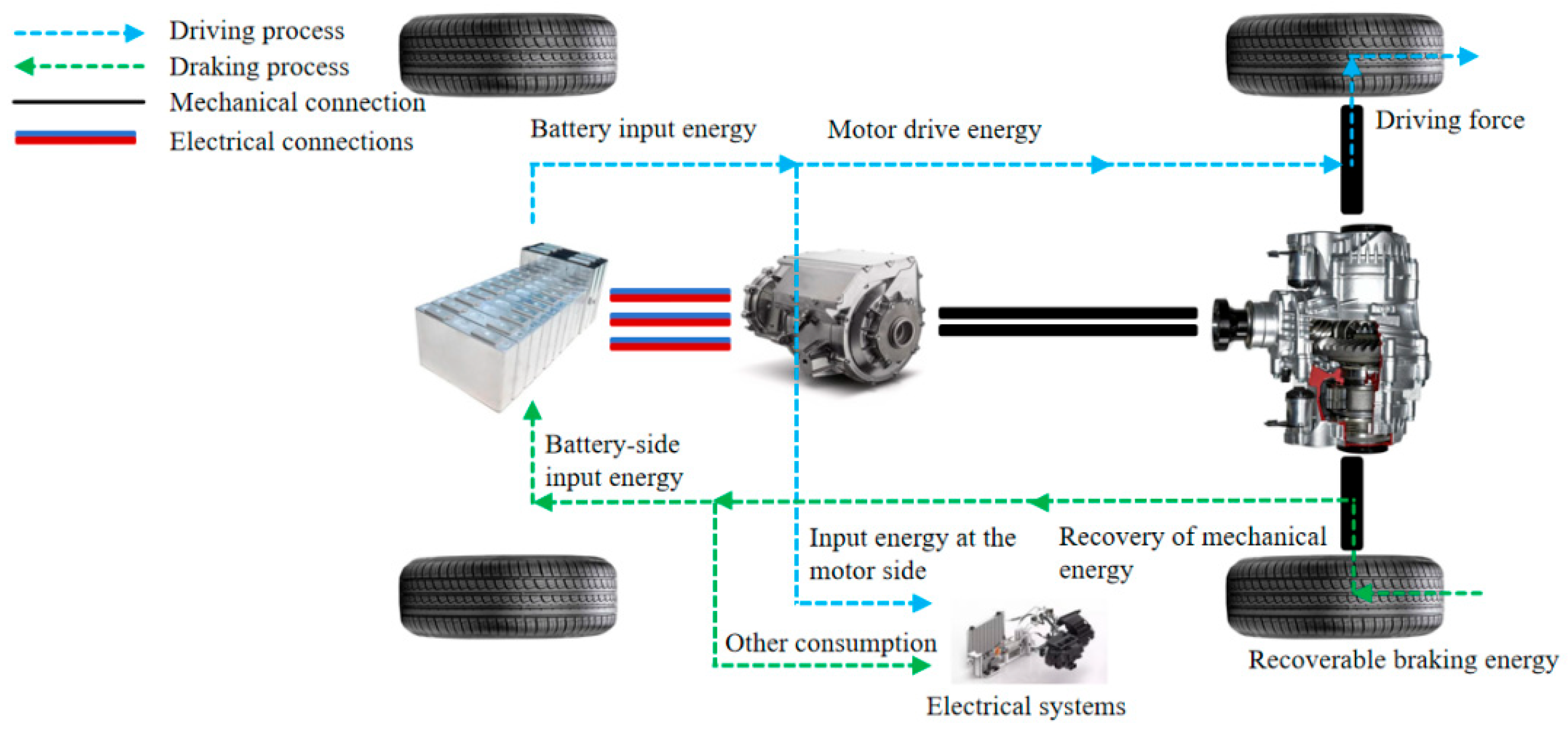
Figure 1 illustrates the working principle of driving and braking energy recovery in BEVs. While driving (represented by the blue dashed energy flow), the battery supplies electrical energy to the motor. The motor converts this electrical energy into mechanical driving energy, which is then transmitted to the wheels via a mechanical connection to propel the vehicle. When braking (represented by the green dashed energy flow), depressing the brake pedal triggers the vehicle control unit (VCU) to activate the energy recovery mode, which is contingent upon the battery’s SOC. The recoverable mechanical energy generated by the wheels during the deceleration is transferred to the motor through the mechanical drivetrain [22]. In this mode, the motor operates in reverse as a generator, converting the mechanical energy into electrical energy. A portion of this recuperated energy is fed back into the traction battery via an electrical connection and is stored as chemical energy, while the remainder is sent to power the vehicle’s electrical accessories [23].
During the brake energy recovery process, except for the energy consumed by aerodynamic drag and rolling resistance, which cannot be recovered, the braking energy is converted from mechanical energy into chemical energy in the battery for electrical storage through generator torque reversal. The brake recoverable energy is defined as:
E reg = E k E f E w
where Ereg denotes the brake recoverable energy; Ek is the change in kinetic energy during the braking process; Ef is the rolling resistance; and Ew is the aerodynamic drag.
Based on the braking energy flow paths among various systems, the regenerative braking energy recovery consists of two consecutive processes [24,25]: (1) the vehicle kinetic energy changes to recoverable braking energy, which is transferred to the drive wheels and then transferred to the half-shafts. Specifically, upon the activation of braking, the kinetic energy of the moving vehicle is converted into recoverable braking energy. The proportion of this recoverable energy varies under different operating conditions (i.e., mild braking, moderate braking, and emergency braking), as during mild braking, a larger portion of the vehicle’s kinetic energy is converted into recoverable energy, while during emergency braking, part of the kinetic energy is dissipated as thermal energy via mechanical braking. Subsequently, this recoverable mechanical energy is transmitted to the half-shaft through the mechanical connection between the drive wheels and the half-shaft as the drive wheels decelerate. (2) The half-shafts send the energy to the transmission system, which is transferred to the motor and then to the battery. The mechanical energy at the half-shaft is transmitted to the motor through the mechanical transmission of the powertrain system. At this point, the motor switches to the power generation mode under the guidance of the brake control strategy, converting the mechanical energy into electrical energy. Ultimately, this electrical energy is transmitted and stored in the battery via the electrical connection path, completing the recovery of the braking energy. The energy output at the motor terminal is expressed as follows:
E 0 = η gen η t λ ( E k E w E f )
where E0 denotes the energy output at the motor terminal; ηt refers to the operating efficiency of the transmission system; ηgen denotes the power generation efficiency of the generator; and λ is the braking force distribution coefficient. Meanwhile, the energy input at the battery terminal is characterized by Equation (3):
E i = η chg η gen η t λ ( E k E w E f )
where Ei denotes the energy input at the motor terminal; ηchg (corresponding to the original ηgen) represents the charging efficiency of the battery.
In the evaluation framework for the brake energy recovery, the energy economy metrics hold significant importance [26]. Of these indicators, the brake energy recovery rate serves as an effective gauge of the proportion of energy captured by the motor relative to the vehicle’s recoverable kinetic energy [27]. The calculation formula for energy recovery efficiency is presented as follows:
η = E i E 0 × 100 %
Here, η represents the energy recovery rate.

2.2. Conventional Brake-Force Distribution Curve

When braking, the forward transfer of the vehicle’s center of mass causes a load shift between the front and rear wheels, which is characterized by an increased load on the front wheels and a decreased load on the rear wheels. If the braking force distribution does not match the tire-road adhesion of the front and rear wheels after the load transfer, the vehicle will experience one of three scenarios during braking: rear-wheel lock-up, front-wheel lock-up, or the simultaneous lock-up of both the front and the rear wheels [28]. The simultaneous lock-up of the front and rear wheels only occurs when the braking force distribution exactly matches the adhesion limits of the front and rear wheels after the load transfer. IBD is defined as a braking force allocation method that enables the front and rear wheels to simultaneously reach the tire-road adhesion limit (i.e., simultaneous lock-up) during braking [29]. Its core objective is to ensure that the front and rear braking forces always match the adhesion limits that correspond to the dynamic axle loads after the load transfer, thereby achieving maximum braking deceleration while guaranteeing braking stability. Equation (5) defines the rear-wheel ground braking force under the ideal braking force distribution condition, and its variables are clarified as follows:
F xb 2 = 1 2 G h g b 2 + 4 h g L G F xb 1 G b h g + 2 F xb 1
where Fxb1 refers to the ground braking force exerted on the front wheels; Fxb2 stands for the ground braking force acting on the rear wheels; hg represents the height of the vehicle’s center of mass; b denotes the distance between the vehicle’s center of mass and its rear axle; and L corresponds to the wheelbase of the vehicle.

2.3. Minimum-Brake-Force Regulation and f-Curve

To maintain vehicle stability when braking at low speeds, the United Nations Economic Commission for Europe (ECE) Automotive Regulation R13—known as the M-curve—sets constraints on the minimum braking force. For vehicles operating with a road surface adhesion coefficient (φ) between 0.2 and 0.8, the braking intensity (z) must meet the requirement: z ≥ 0.1 + 0.85(φ − 0.2). Under the ECE Regulation, the front-to-rear braking force allocation must adhere to the equation below:
h g ( F xb 1 + F x b 2 ) 2 m g L + F xb 1 + F xb2 L b + 0.07 h g + 0.07 m g b L 0.85 F xb 1 = 0
In the event that the front wheel locks up, the equation defining the ground adhesion (f) for both front and rear wheels is given by the following:
F xb2 = ( L φ h g ) F xb 1 φ h g m g b h g

2.4. Front–Rear Brake-Force Distribution Strategy

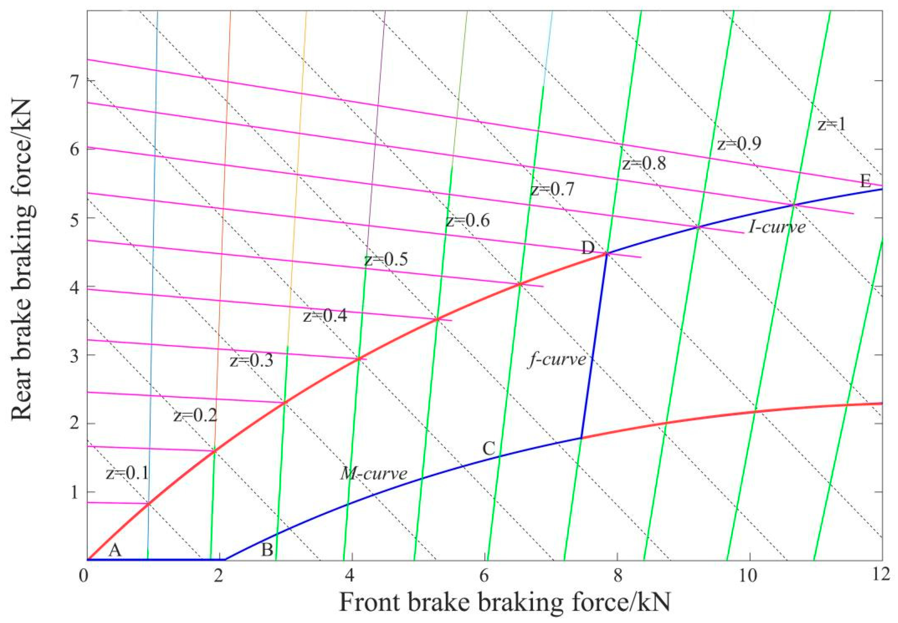
Conventional vehicles generally implement braking force allocation following the I-curve. To guarantee braking safety and stability, the front–rear braking force allocation must be restricted to the area enclosed by the M-curve, I-curve, and f-curve (see Figure 2). Specifically, within the braking force allocation control strategy, for low to moderate braking intensities, electric braking should be favored as much as feasible to boost the brake energy recovery efficiency; from a safety standpoint, electric braking should be scaled back or fully deactivated during high-intensity braking. Given the vehicle parameters adopted in this research, the braking force allocation strategy (prioritizing energy recovery) follows these guidelines:
(1) When 0 ≤ Z ≤ 0.125: Braking force is allocated along line AB. This aligns with the mild braking conditions, where the electric motor alone supplies the braking force, and no hydraulic braking force is used;
(2) When 0.125 ≤ Z ≤ 0.7: Braking force allocation occurs along line BCD. This applies to moderate braking intensity, where the braking force comes from a combination of the electric motor and hydraulic system;
(3) When 0.7 ≤ Z ≤ 1: Braking force is allocated along line DE. This falls under emergency braking scenarios, where the braking force is supplied entirely by the hydraulic system.

3. Development of Braking Energy Recovery Control Strategy

3.1. Regenerative Braking Control Strategy

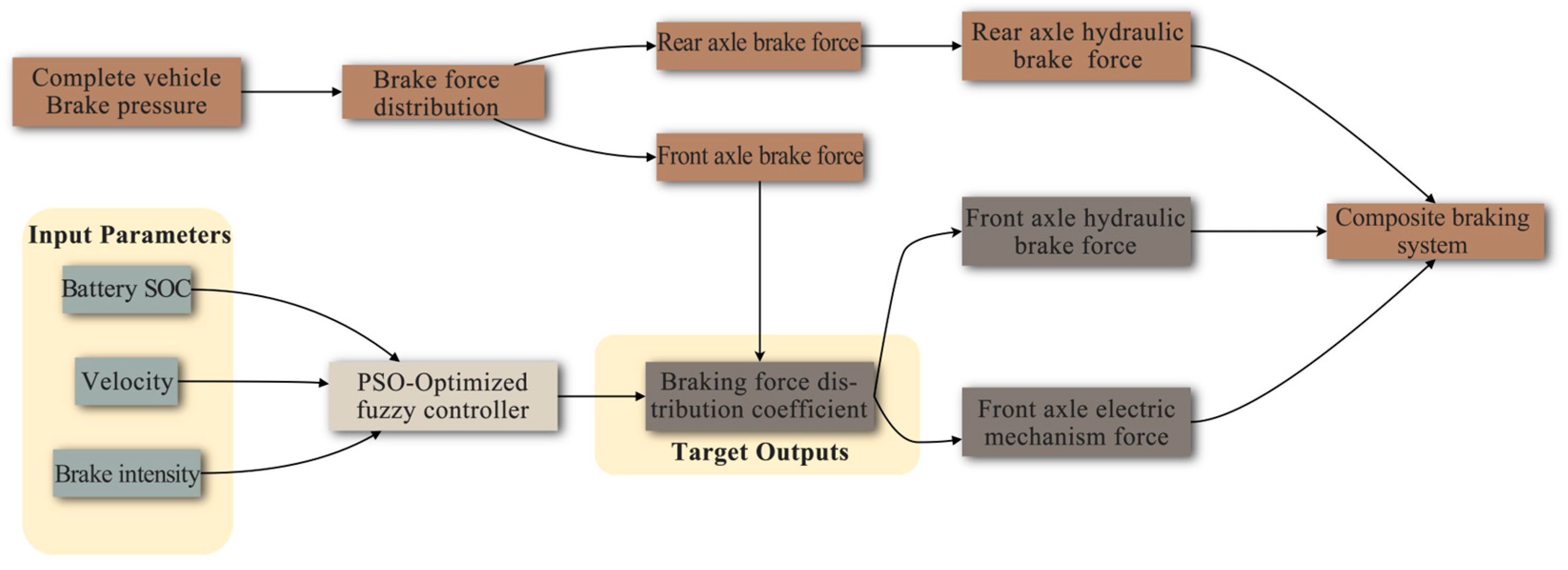
The regenerative braking control strategy employed in this study initially allocates the required front- and rear-wheel braking forces based on the total demanded braking torque, which is in line with the theoretical framework outlined in the preceding section. Subsequently, the hydraulic braking force and the electromechanical braking force required for the front axle are determined by accounting for three critical parameters: battery SOC, braking intensity, and vehicle speed. As depicted in Figure 3, this diagram illustrates the architecture of the energy recovery control strategy that is tailored for BEVs.

3.2. FC

FC is an intelligent control method based on fuzzy logic, designed to emulate human decision-making under uncertainty. It does not depend on an accurate and precise mathematical model of the controlled system and offers advantages in robustness and real-time performance when applied to uncertain and nonlinear systems [30,31]. In the context of the regenerative braking force control for BEVs, FC effectively addresses the core challenge of strong coupling and nonlinearity among multiple braking system parameters—such as vehicle speed, battery SOC, brake pedal travel, and road adhesion coefficient. By dynamically optimizing the distribution ratio between the regenerative braking force and the mechanical braking force, the approach maximizes the braking energy recovery, thereby enhancing the vehicle’s driving range. The FC strategy developed in this study adopts a three-input-one-output structure. The input variables are braking intensity, vehicle speed, and battery SOC, while the output variable is the ratio of electric braking force to the total braking force acting on the drive axle, and relevant details are elaborated as follows:
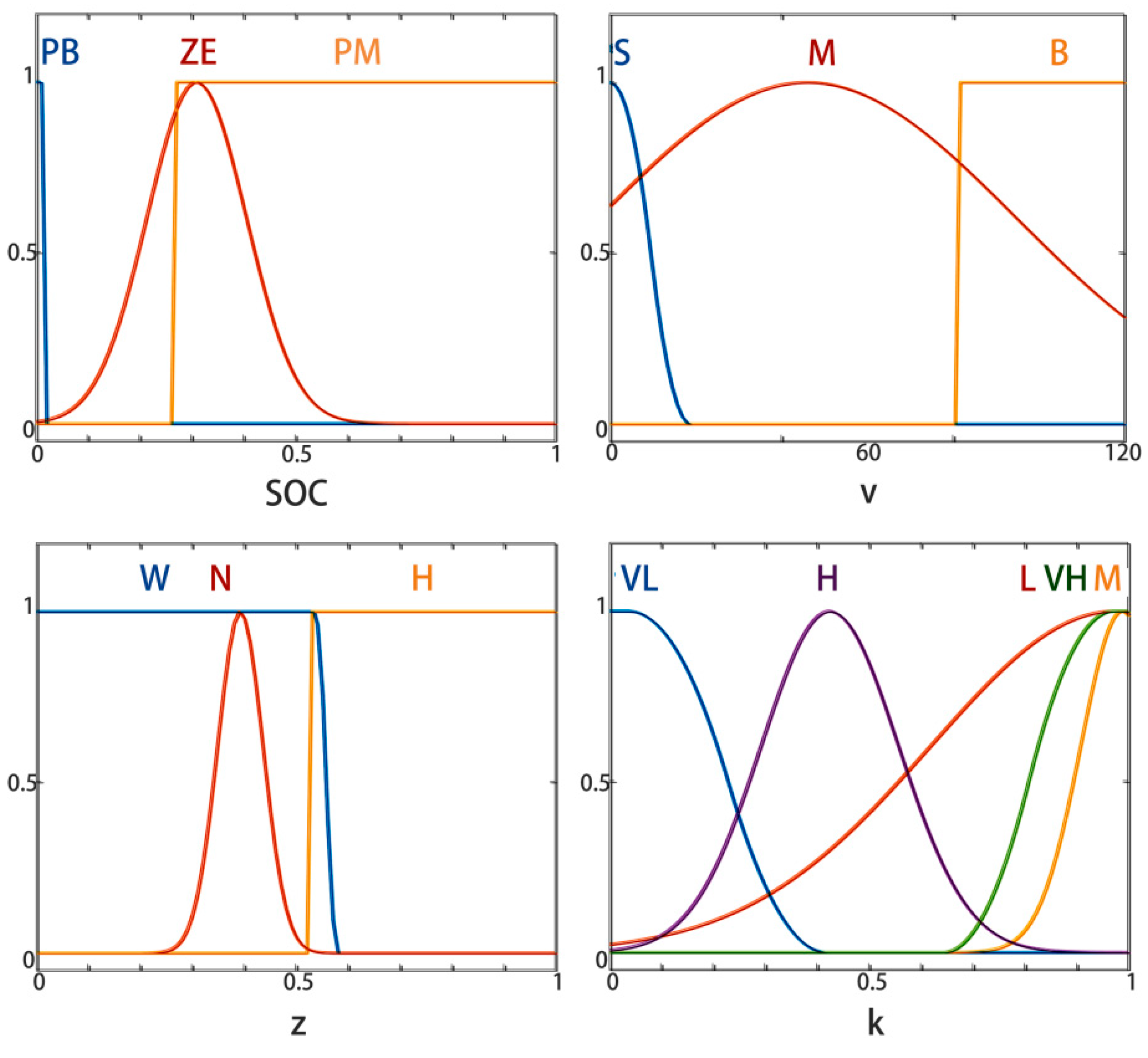
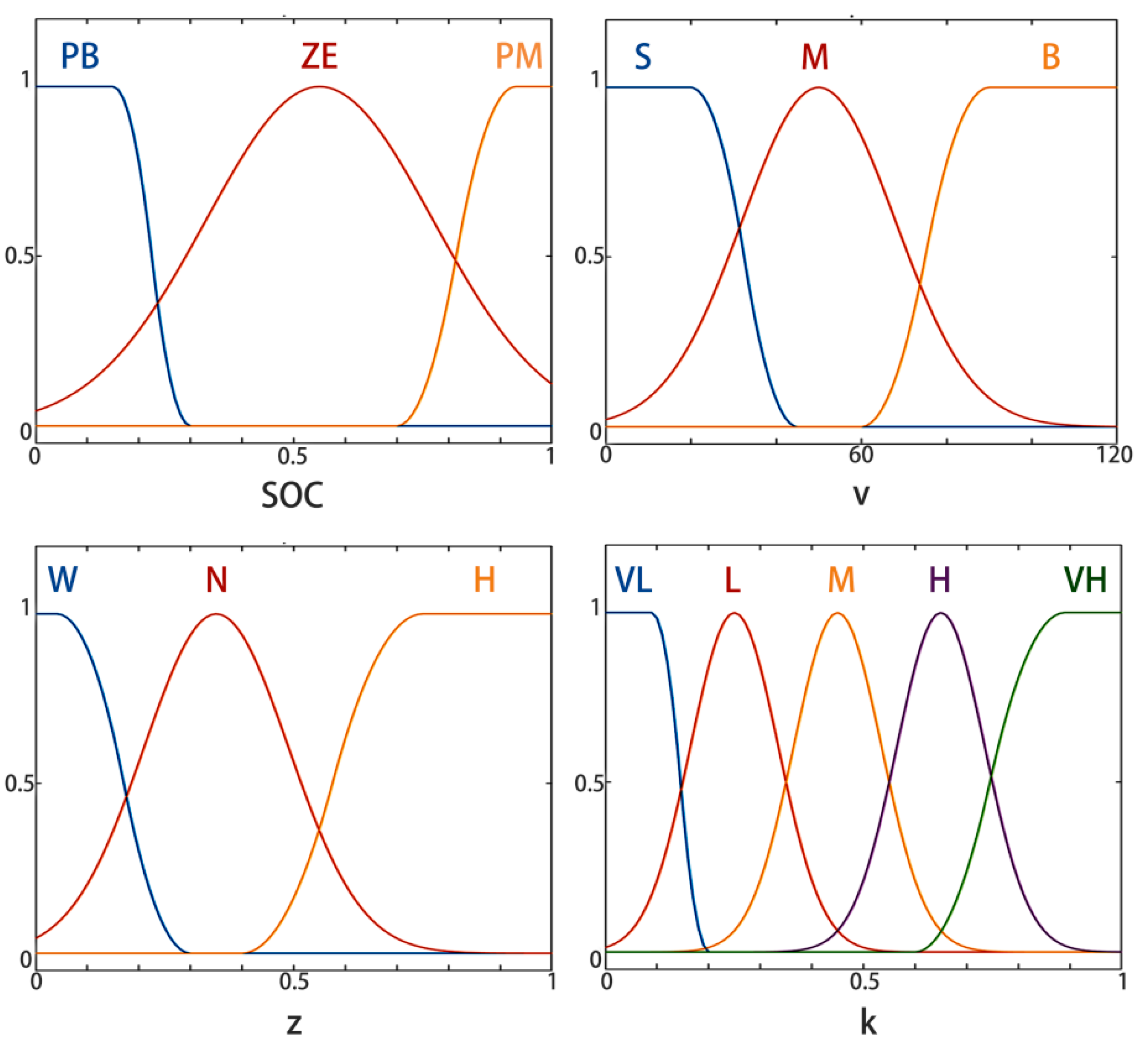
The SOC reflects the remaining capacity of the traction battery. Its fuzzy universe of discourse is [0, 1], with a quantization level of three. The fuzzy subsets are defined as small, middle, and large, which are abbreviated as PB, ZE, and PM, corresponding to low, medium, and high battery SOC states, respectively. The membership functions for fuzzy subsets PB, ZE, and PM adopt zmf, gaussmf, and smf, respectively. For the vehicle speed input, the fuzzy universe of discourse is [0, 120] km/h (based on standard automotive engineering conventions), also with a quantization level of three. The fuzzy subsets are low, middle, and high, abbreviated as S, M, and B, corresponding to low, medium, and high driving speeds, respectively. The membership functions for S, M, and B use zmf, gaussmf, and smf, respectively. The braking intensity serves as an indicator of driver braking demand. Its fuzzy universe is [0, 1], with three quantization levels and the fuzzy subsets of small, middle, and large, abbreviated as W, N, and H, corresponding to low, moderate, and high braking intensity. The associated membership functions are zmf, gaussf, and smf, respectively. The electric braking force ratio defines the proportion of the motor’s regenerative braking force relative to the total braking force on the drive axle. For this output variable, the fuzzy universe is also [0, 1], with a quantization level of five. The fuzzy subsets are very low (VL), low (L), middle (M), high (H), and very High (VH), representing progressively increasing contributions of regenerative braking force. The membership functions for these subsets are as follows: VL uses zmf; L, M, and H employ gaussf; and VH applies smf. The complete set of FC rules is illustrated in Figure 4.
On the premise of fully ensuring the vehicle braking stability and safety, the motor’s regenerative braking force should be utilized as much as possible to maximize the brake energy recovery performance. Therefore, the formulation of FC rules needs to integrate expert experience and knowledge with theoretical analysis. The FC rule statement proposed in this study is: if (z is z) and (v is v) and (SOC is SOC) then (k is k), as shown in Table 1.

3.3. PSO-Optimized FC Rule Base

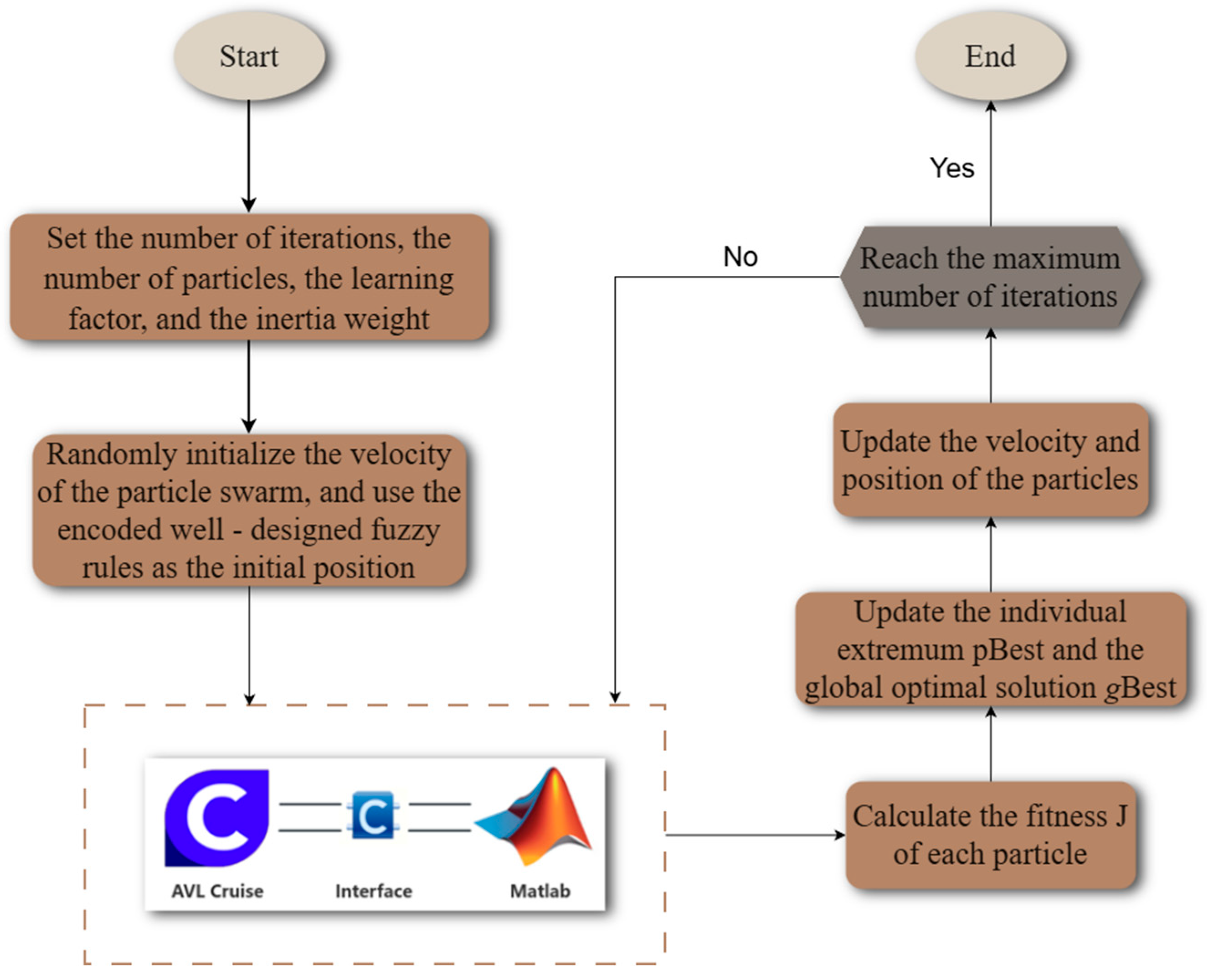
The PSO algorithm is a swarm intelligence optimization algorithm whose design inspiration is derived from the simulation of birds’ foraging behavior [32,33]. In PSO, each particle is abstracted as a massless entity with only two basic attributes: velocity and position. Among these, velocity characterizes the moving speed of the particle in the search space, while the position reflects the specific coordinates of the particle within that space. To address the FC optimization requirements, a continuous real-valued encoding scheme is adopted for PSO particles, which aligns with PSO’s velocity-position update mechanism and avoids a precision loss from binary/integer encoding. Each particle’s position vector maps exactly to 28 continuous FC parameters, including the inflection points, means, and standard deviations of the membership functions for inputs (braking intensity z, speed v, SOC) and output (regenerative braking ratio k). The core goal of maximizing the regenerative braking energy recovery efficiency (η) is converted to a minimization problem for standard PSO implementation, which is defined as follows:
m i n J = 1 η = 1 E r e c o v e r e d E k i n c t i c
where Erecovered represents the electrical energy actually recovered by the traction battery during braking, and Ekinctic denotes the total kinetic energy of the vehicle before braking initiation. The k is the dynamic output of the optimized FC. The k is determined by the FC parameters encoded in the particle position, and its optimal variation trend is indirectly realized by minimizing the objective function J. Each particle tracks its personal best (pBest) and shares information to update the swarm’s global best (gBest), dynamically adjusting the velocity and position to approach the global optimum. Benefiting from easy implementation, fast convergence, and minimal parameter tuning, PSO is widely applied in function optimization, neural network training, and FC parameter tuning. The PSO-based FC framework is illustrated in Figure 5. Its constraints and objective function are expressed as follows:
g i ( x ) 0 , i = 1 , 2 , , m min f ( x ) = 1 F ( x )   X j 1 X j X j 2 , j = 1 , 2 , , n
In this formulation: gi(x) corresponds to the constraint conditions; f(x) is the function defined within the objective function; F(x) represents the energy recovered during the vehicle’s operational process; [ X j 1 , X j 2 ] represents the value range; m is the total number of constraint conditions; n refers to the number of variables; and X j is the designated design variable.
In the initial phase of the PSO algorithm, the swarm searches for the optimal solution through a series of iterative processes [34]. During each iteration, each particle updates two key extreme values: one is the optimal solution found by the particle itself during the search process, referred to as the pBest, and the other is the optimal solution found by the entire swarm during the search process, referred to as the gBest [35]. Based on these two extreme values, the particle dynamically adjusts its own velocity and position. Their respective update formulas are given by Formula (10), and the updates of the particle’s position and velocity are derived through calculation.
v k + 1 = ω v k + c 1 r 1 p i d k x k + c 2 r 2 p g d k x k x k + 1 = x k + v k + 1
These symbols correspond to core parameters in the PSO algorithm, with their definitions specified as follows [36,37]:
Where ω is the inertia weight coefficient, a non-negative scalar typically spanning the interval 0.1 to 0.9; k is the number of iterations executed in the optimization process; xk+1 is the positional coordinate of the i-th particle in the (k + 1)-th generation of the swarm; xk is the positional coordinate of the i-th particle in the k-th generation; vk+1 is the velocity vector of the i-th particle in the (k + 1)-th generation; vk is the velocity vector of the i-th particle in the k-th generation; p i d k is the pBest of the i-th particle in the k-th generation; p g d k is the gBest of the entire swarm in the k-th generation; ri (i = 1, 2) is the random numbers within the interval (0, 1); ci (i = 1, 2) is the learning factors, typically set to c1 = c2 = 2; d takes the values in the range [1, 2, …, D], where D denotes the spatial dimension (i.e., the number of independent variables); and I takes the values in the range [1, 2, …, N], where N denotes the particle swarm size.
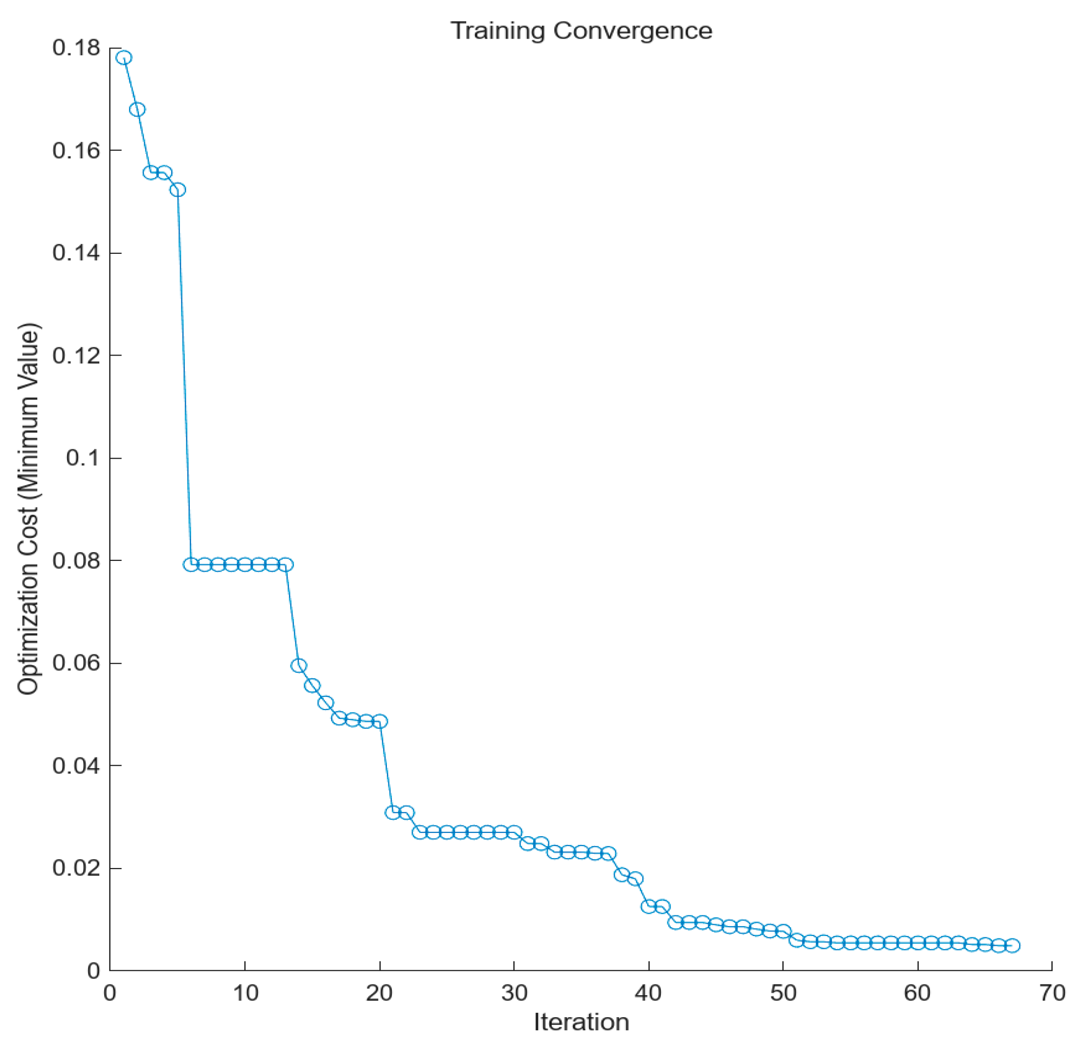
This study leverages the PSO algorithm to optimize the FC framework, with the objective of enhancing the reliability of the outcomes obtained. The FC strategy developed in this work incorporates three input variables: vehicle braking intensity (denoted as z), SOC of the traction battery, and vehicle operating speed (denoted as v). The corresponding output variable is k, which represents the regenerative braking force allocation coefficient of the motor. In the construction of the fuzzy rule base for this FC strategy, the widely accepted “Don’t Care (DC)” condition (mapped to the “None” placeholder in the MATLAB 2017a Fuzzy Logic Toolbox) is introduced to simplify the rule structure: for specific input combinations where a single variable has no significant impact on the output k, the DC condition is applied to exclude the irrelevant variable from the fuzzy inference, ensuring the completeness of the rule base while reducing the computational complexity. The core objective of this FC strategy is to elevate brake energy recovery efficiency—a performance metric that exhibits a strong correlation with the motor’s regenerative braking force allocation coefficient k. To optimize the operational performance of the FC framework, this study designates the FC’s output parameter k as the fitness function for the PSO algorithm. The initialization parameters corresponding to the PSO algorithm are summarized in Table 2, while the fitness curve of the defined function is visualized in Figure 6.
Based on the above description, the FC was optimized using the PSO algorithm, and the optimized membership functions and the FC rules were successfully obtained. The optimized FC rules are presented in Table 3, while the optimized input and output membership functions are illustrated in Figure 7, respectively.

4. Simulation and Results Analysis

4.1. Model Establishment

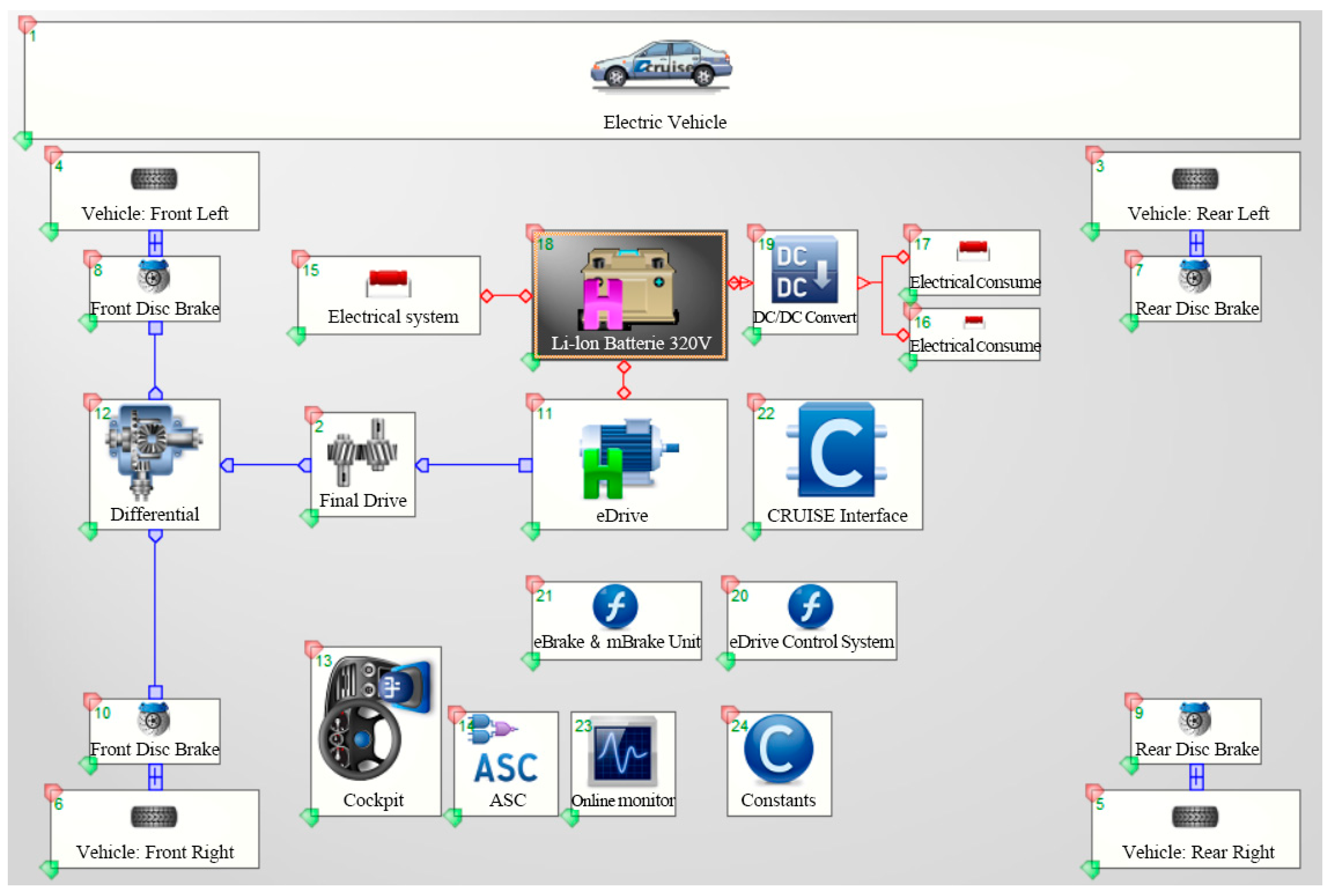
In the field of automotive simulation, commonly used software includes AVL-Cruise, CarSim, Advisor, and AMESim, among others. AVL-Cruise is a powerful simulation tool specializing in the simulation of vehicle powertrain economy, emissions, and dynamics [38,39]. Its modular modeling feature greatly simplifies the construction process of different types of vehicle models. Additionally, AVL-Cruise 2019 can efficiently build vehicle models that are integrated with brake energy recovery systems, and through co-simulation with Matlab/Simulink 2017a, it can fully leverage its advantages in complex system simulation. Based on these characteristics, this study selects AVL-Cruise 2019 as the primary simulation software. In this experiment, to comprehensively evaluate the vehicle performance, two standard driving cycles are adopted for simulation testing: NEDC and WLTC. The vehicle simulation model is illustrated in Figure 8, providing crucial data support for the subsequent analyses.
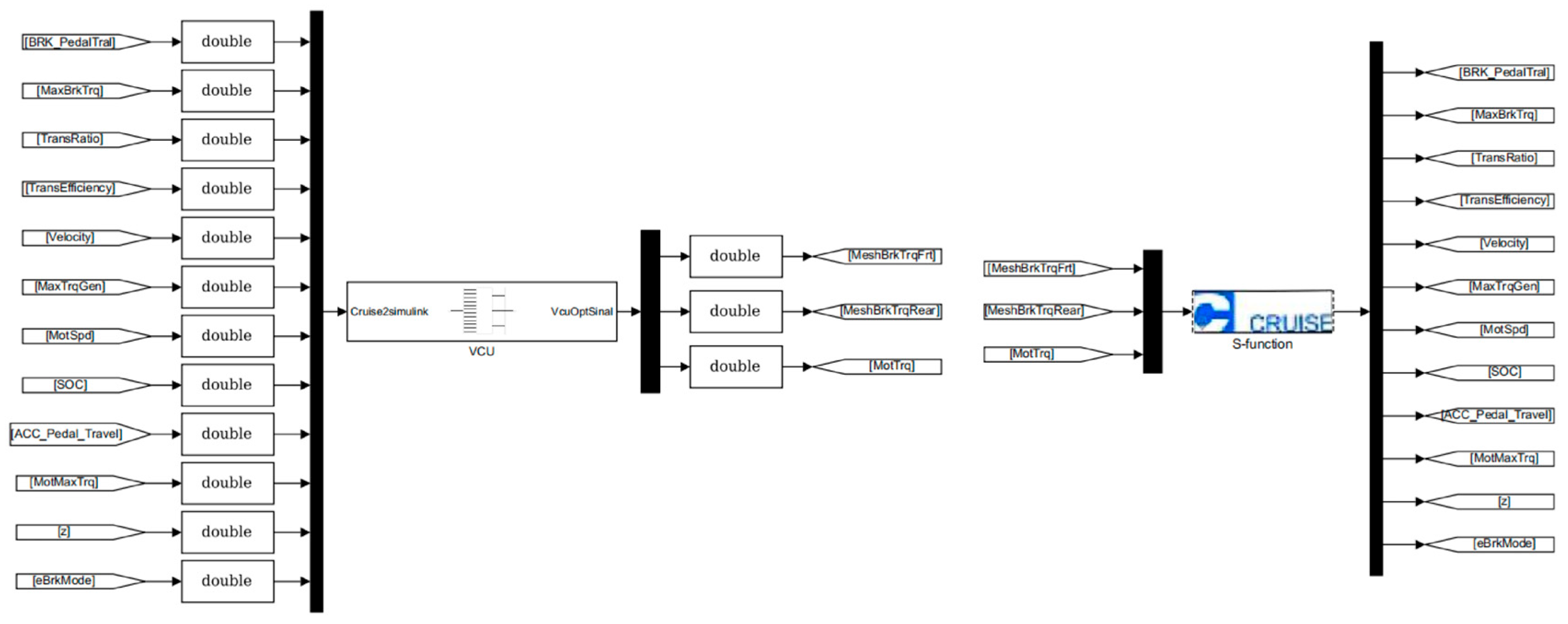
For the purpose of co-simulation investigation, this study establishes a model corresponding to the brake energy recovery control strategy within the MATLAB/Simulink 2017a simulation platform and interfaces the Simulink ports via the interface module integrated in CRUISE, thus enabling the real-time simulation capabilities. The detailed implementation process of the brake energy recovery control approach is depicted in Figure 9. Table 4 summarizes the core parameters associated with a front-wheel-drive battery electric vehicle.

4.2. Simulation Results and Analysis

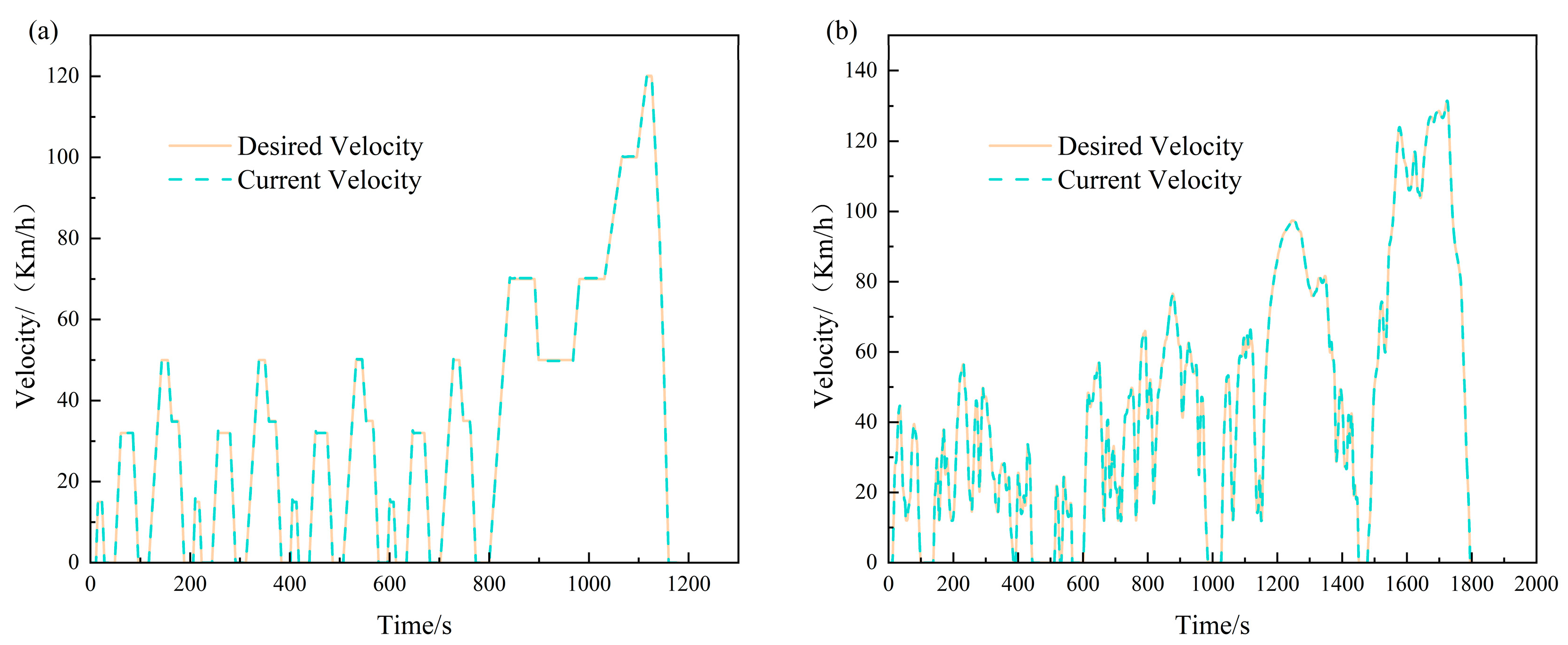
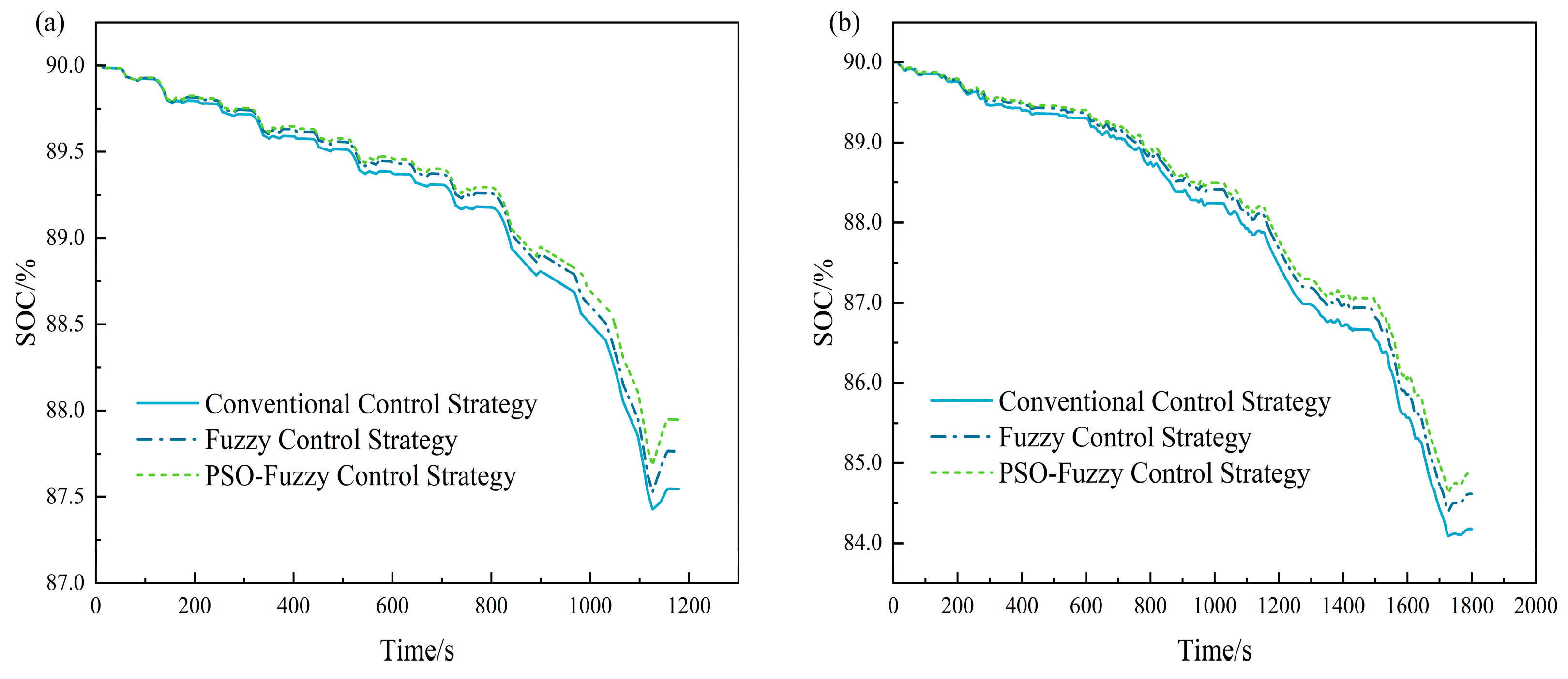
Within the CRUISE simulation environment, the road adhesion coefficient is configured to 0.7, the ambient temperature is set to 20 °C, and the wind effects are neglected. This study conducts a comparative analysis between the proposed PSO-optimized FC strategy, the conventional FC strategy, and the ideal braking force distribution control strategy under the NEDC and WLTC, aiming to validate the effectiveness of the proposed optimized strategy. Figure 10 illustrates the comparison between the actual vehicle speed and the target vehicle speed under both the NEDCs and WLTCs. As depicted in this figure, the actual vehicle speed can closely follow the variations in the target vehicle speed. Figure 11 presents a comparison of the remaining battery SOC under the ideal braking force distribution control strategy, the conventional FC strategy, and the PSO-optimized FC strategy across both driving cycles. The initial battery SOC for the electric vehicle’s brake energy recovery process is set to 90%. The key observations are summarized as follows:
(1) Under the NEDC: (1) With the ideal braking force distribution control strategy: the battery SOC decreases from 90% to 87.5442%; (2) with the proposed FC strategy: the battery SOC decreases from 90% to 87.7644%; (3) with the PSO-optimized FC strategy: the battery SOC decreases from 90% to 87.9530%. Relative to the conventional FC strategy, the battery SOC is increased by 0.2513%, and in comparison to the ideal braking force distribution control strategy, the battery energy consumption is reduced by 0.4670%.
(2) Under the WLTC: (1) With the ideal braking force distribution control strategy: the battery SOC decreases from 90% to 84.1746%; (2) with the proposed FC strategy: the battery SOC decreases from 90% to 84.6125%; (3) with the PSO-optimized FC strategy: the battery SOC decreases from 90% to 84.88%. Relative to the conventional FC strategy, the battery SOC is increased by 0.520%, and in comparison to the ideal braking force distribution control strategy, the battery energy consumption is reduced by 0.8380.
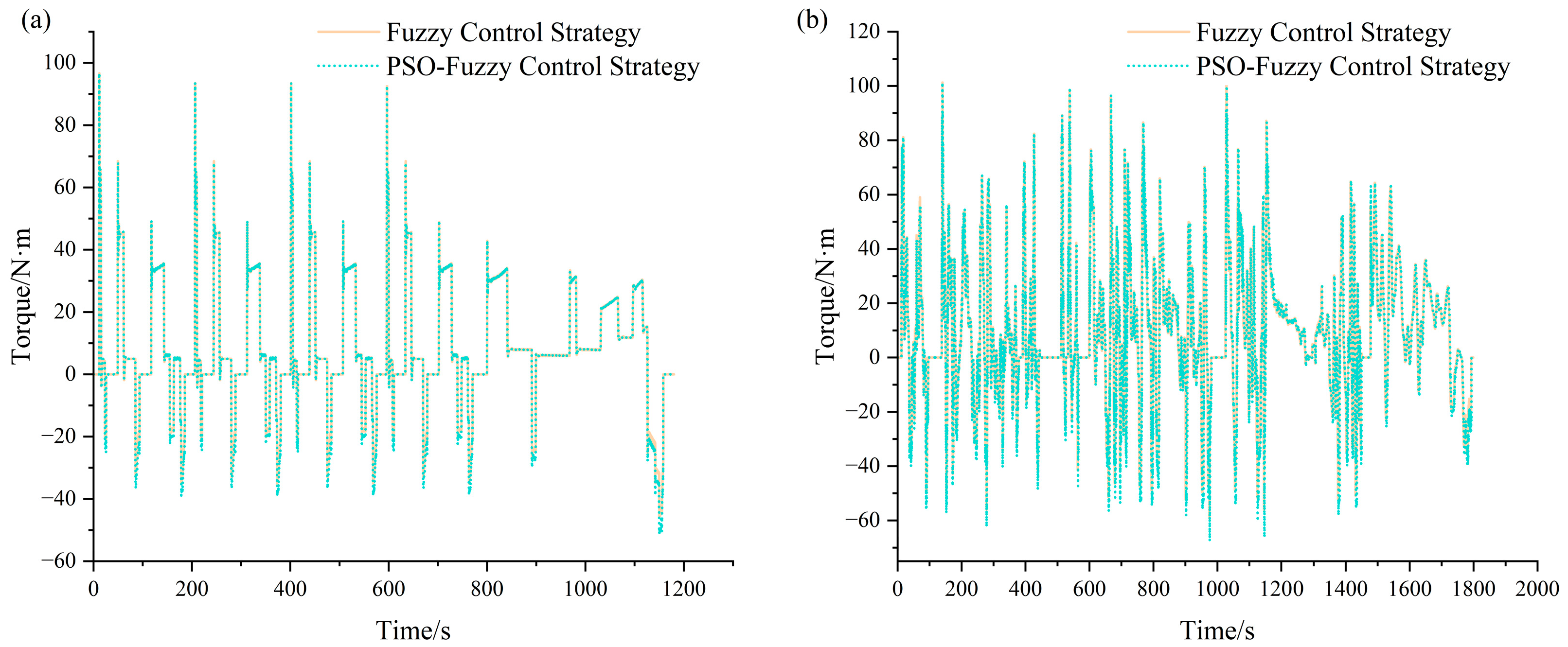
Figure 12 shows that under both driving cycles, the negative torque generated by the motor under the optimized FC strategy is significantly higher than that under the unoptimized FC strategy.
Table 5 presents the total energy input and output of the vehicle under the NEDC and WLTC driving cycles in this study.
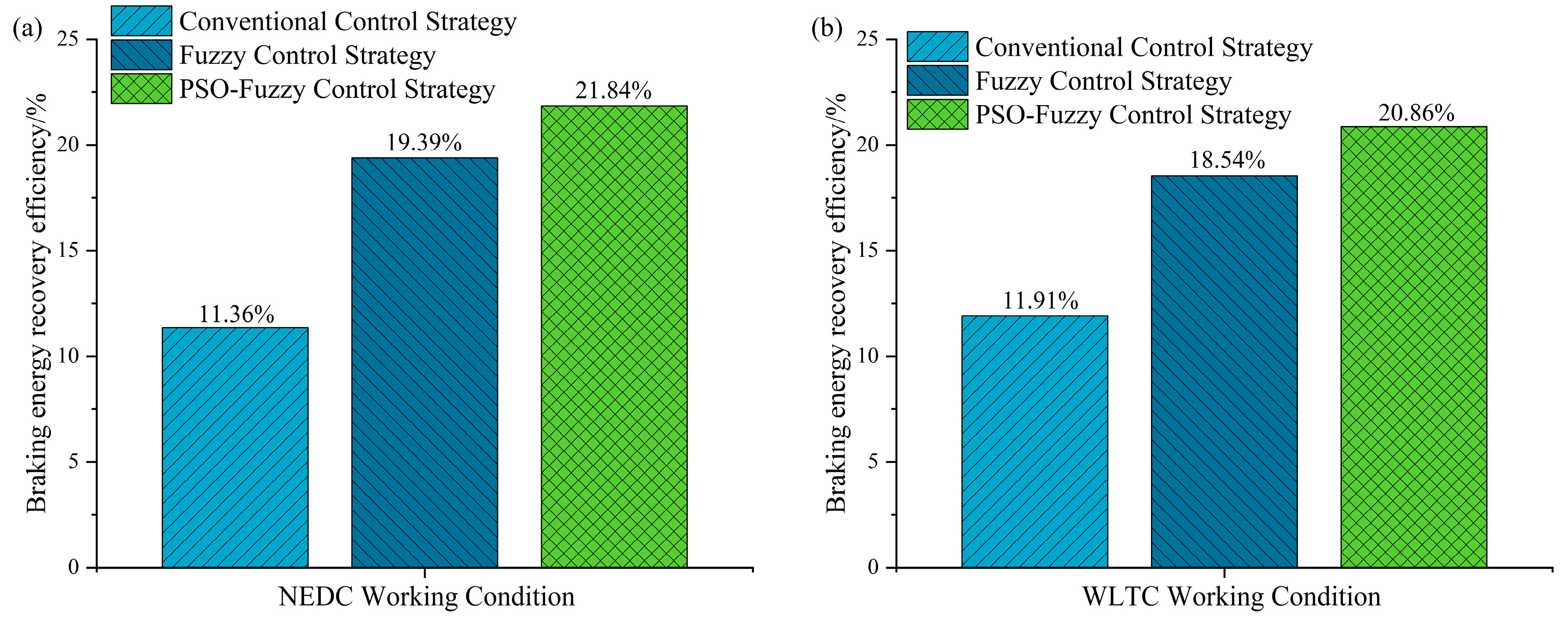
Following the data processing and computation, Figure 13 presents the energy recovery rates of distinct control strategies across both driving cycles. Under the NEDC, the energy recovery rate of the FC strategy exceeds that of the ideal braking force distribution strategy by 8.03%, while the energy recovery rate of the optimized FC strategy is 10.49% higher than this ideal counterpart. For the WLTC, the FC strategy achieves an energy recovery rate that is 6.65% greater than the ideal braking force distribution strategy, and the optimized FC strategy further elevates this performance metric by 8.95% relative to the ideal strategy.

4.3. Real-Time Verification of HIL Test

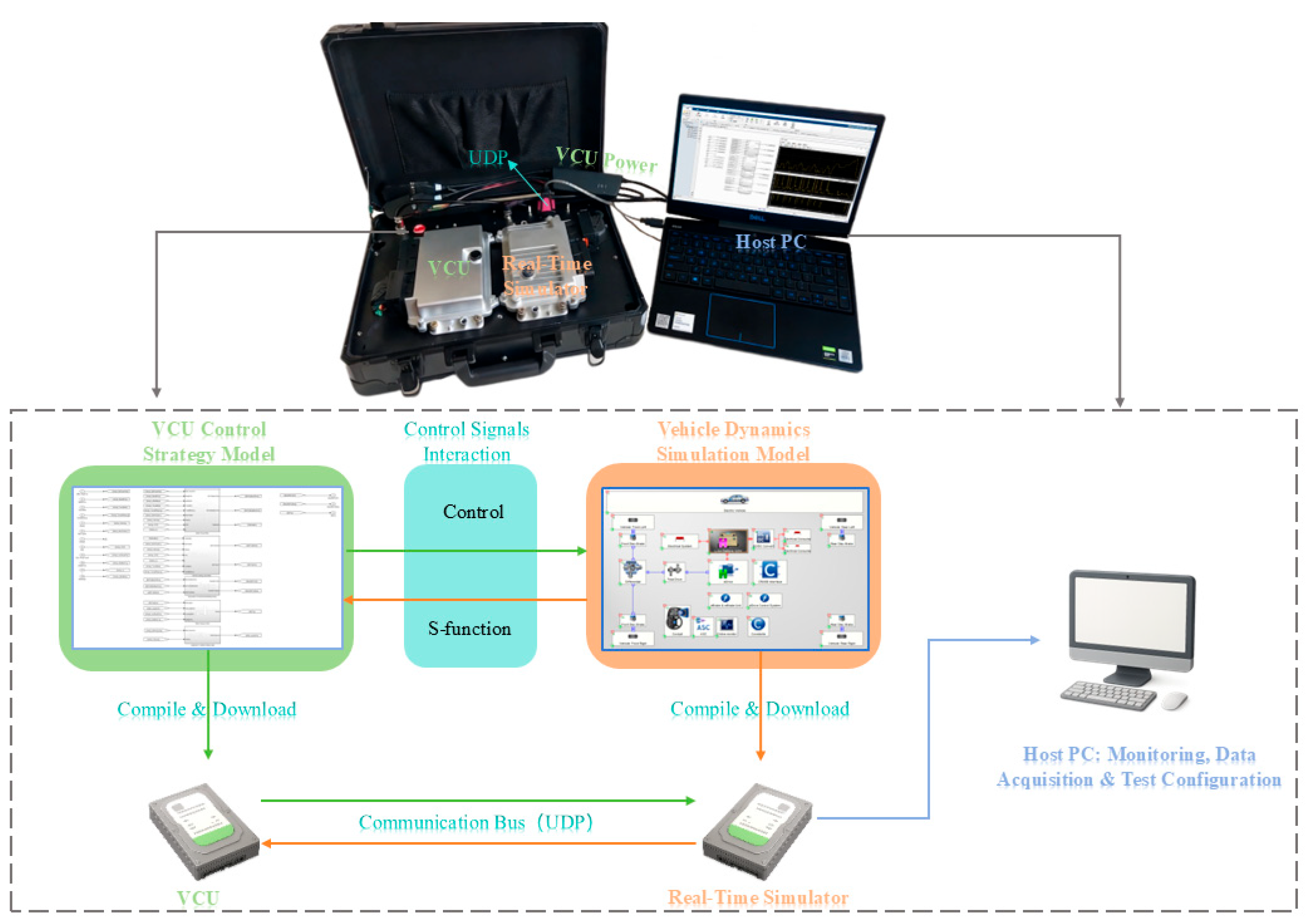
To evaluate the real-time performance of the optimization algorithm, this study conducted experiments on a HIL test bench with systematically designed test scenarios (covering standard driving cycles, steady-state/transient braking, and extreme conditions including emergency braking and ABS intervention), with the experimental equipment detailed in Table 6. The test procedure, illustrated in Figure 14, is described as follows. First, the hardware connection and initial system configurations are established. The signal communication between the real-time target machine and the VCU is achieved via a UDP link, and the VCU is powered by a dedicated VCU power supply. The vehicle dynamics braking system and ABS control models are deployed in the real-time target machine, while monitoring software that is running on a laptop is initialized with predefined driving cycle parameters and configured for the synchronous acquisition of real-time control performance metrics. During the test, the real-time target machine simulates various driving and braking conditions (including emergency braking events and ABS intervention triggered by an excessive wheel slip rate) and transmits the corresponding signals to the VCU. The VCU executes the regenerative braking control strategy and outputs braking force distribution commands, which are fed back to the real-time target machine to realize the dynamic interaction of the control loop. Throughout the experiment, real-time data—including the electric braking force ratio, battery SOC variation, braking force response, as well as quantitative metrics of end-to-end signal transmission delay, core control task execution cycle time, and real-time CPU load of the VCU and simulator—are collected and displayed via the host PC monitoring interface. Upon completion of the test, the recorded data are post-processed to assess the real-time responsiveness, energy recovery efficiency, and coordination characteristics of the braking force distribution. This completes the HIL test validation process.
The HIL test system for real-time verification is presented in Figure 14. The system consists of three core modules: the host PC, the real-time simulator, and the tested VCU. As shown in the figure, the vehicle dynamics simulation model and the proposed PSO-FC strategy model are compiled and downloaded to the real-time simulator and VCU, respectively. The closed-loop signal interaction between the VCU and the real-time simulator is realized via the UDP communication bus, while the host PC completes test configuration, real-time state monitoring and full-process data acquisition.
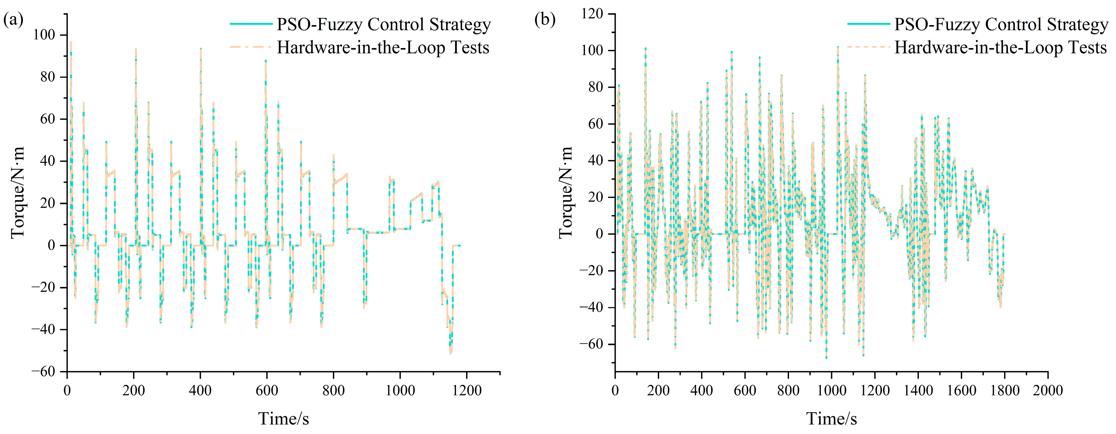
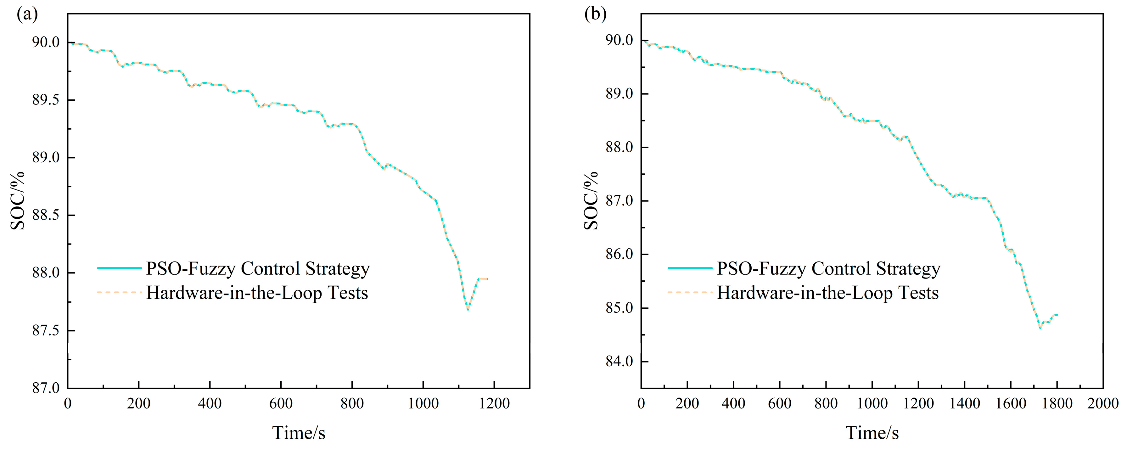
The HIL test results are shown in Figure 15 and Figure 16: After deploying the PSO-optimized fuzzy control strategy to the actual controller, the output motor torque curve and vehicle battery SOC curve exhibit good consistency with the corresponding curves from the simulation phase. The consistency of the aforementioned curves verifies that the control strategy that is implemented in the VCU can effectively achieve real-time regulation of the vehicle braking system, ensuring its dynamic response is consistent with the expected characteristics. A quantitative consistency analysis is conducted on the HIL test results to validate the performance of the proposed PSO-FC strategy. Under the NEDC and WLTC driving cycles, the motor torque between the HIL test and the simulation yields a maximum relative error below 5% and a dynamic response time deviation of less than 10 ms; the absolute error of the final battery SOC is only 0.0518 and 0.0675 percentage points, respectively, with a full-cycle relative error below 0.08%. This result further confirms that the proposed control algorithm possesses excellent real-time performance and can meet the timing requirements of the actual vehicle dynamic control.

5. Conclusions

To address the challenges of the reduced regenerative braking efficiency and compromised braking safety in BEVs under frequent start–stop driving conditions, this study proposes an optimization method for FC based on the PSO algorithm. The approach enables a collaborative optimization of both the membership functions and the control rules of the FC strategy. A co-simulation platform integrating AVL-Cruise 2019 and Matlab/Simulink 2017a was established, and comparative verifications were carried out under the NEDC and WLTC to assess the practical performance of the proposed strategy. The main conclusions are as follows:
(1) Under the NEDC driving cycle, the battery SOC drops from an initial 90% to 87.5442% when employing the ideal braking force distribution strategy, to 87.7644% via the proposed FC strategy, and to 87.9530% with the PSO-optimized FC strategy. In detail, relative to the baseline FC strategy, the optimized strategy elevates the battery SOC by 0.2515%; this value also represents a 0.4670% improvement over the ideal braking force distribution strategy. Furthermore, the FC strategy boosts energy recovery efficiency by 8.03% compared to the ideal strategy, while the PSO-optimized FC strategy extends this efficiency enhancement to 10.48% above the ideal benchmark.
(2) For the WLTC driving cycle, the battery SOC initially declines from 90% to 84.1746% when utilizing the ideal braking force distribution strategy, to 84.6125% through the proposed FC strategy, and to 84.88% with the PSO-optimized FC strategy. Relative to the standard FC strategy, the optimized approach increases the battery SOC by 0.5202%—a value that also marks a 0.8380% gain over the ideal braking force distribution strategy. Additionally, the FC strategy improves energy recovery efficiency by 6.63% relative to the ideal strategy, while its PSO-optimized variant achieves an 8.95% efficiency lift compared to this ideal baseline.
(3) The HIL test results demonstrate that the PSO-optimized fuzzy control strategy applied to the actual controller yields highly consistent outcomes with simulation results. The quantitative consistency analysis confirms that under the NEDC and WLTC driving cycles, the maximum relative error of the motor torque between the HIL tests and the simulations is below 5%, with a dynamic response time deviation of less than 10 ms; the absolute error of the final battery SOC is only 0.0518 and 0.0675 percentage points, respectively, and the full-cycle relative error is below 0.08%. This verifies the authenticity, accuracy and favorable real-time performance of the proposed method. The strategy exhibits sound engineering application feasibility and can effectively balance the regenerative braking efficiency and braking safety of the BEVs under frequent start–stop urban driving conditions. Meanwhile, the collaborative optimization of membership functions and control rules constitutes the core innovative feature of the proposed PSO-FC strategy.
(4) To further promote the engineering application and performance improvement of the proposed PSO-FC strategy, systematic future research will be implemented. The performance of the strategy will be fully verified under extreme high and low temperature environments. The smoothness of the transitions between the regenerative braking and the hydraulic braking will be evaluated from the perspectives of the driver’s perception, the vehicle jerk, and the braking system NVH performance, so as to build a more comprehensive assessment system. In addition, detailed schemes for real-vehicle road tests will be formulated, and the cost analysis of integrating the proposed strategy into commercial BEV products will be carried out. Moreover, the long-term impact of frequent regenerative braking on battery state of health (SoH) will be deeply explored to provide a complete theoretical and practical support for the popularization of the strategy.


Author Contributions

Conceptualization, J.L.; software, J.L., G.F., B.C., J.Y. and Z.H.; formal analysis, J.L., G.F., B.C., J.Y. and Z.H.; investigation, J.L., G.F., B.C., Z.H., J.Y., J.H., H.H., Z.L., D.H. and F.J.; resources, J.L.; writing—original draft preparation, J.L., G.F., B.C. and Z.H.; writing—review and editing, J.L., G.F., B.C., Z.H., J.Y., J.H., H.H., Z.L., D.H. and F.J.; supervision, J.L.; funding acquisition, J.L., G.F., B.C. and Z.H. All authors have read and agreed to the published version of the manuscript.

Funding

This work is supported by the Guangxi Key Research and Development Program Project (project number: GuiKeAB25069449), the Guangxi National Science and Technology Major Project (project number: GuiKeAA24206064), and the “Jianfeng” Action Plan (Guangxi Key Special Project Program) (project number: GuiKeJF2503980004).

Data Availability Statement

The original contributions presented in this study are included in the article. Further inquiries can be directed to the corresponding author.

Conflicts of Interest

The authors declare no conflict of interest.

Nomenclature

AfThe windward area
bThe distance between the vehicle’s center of mass and its rear axle
CdThe air resistance coefficient
EregThe brake recoverable energy
EkThe change in kinetic energy
EfThe energy consumed by rolling resistance
EwThe energy consumed by aerodynamic drag
E0The energy output at the motor terminal
EiThe energy input at the motor terminal
Fxb1The ground braking force of the front wheels
Fxb2The ground braking force of the rear wheels
gAcceleration due to gravity
hgThe height of the vehicle’s center of mass
LThe wheelbase of the vehicle
rThe wheel radius
TmotorThe motor regenerative torque
vThe vehicle operating speed
VratedThe rated voltage
zThe braking intensity
ηThe energy recovery rate
ηtThe operating efficiency of the transmission system
ηgenThe power generation efficiency of the generator
ηchgThe charging efficiency of the battery
λThe braking force distribution coefficient
φThe road surface adhesion coefficient
c1, c2The learning factors
f(x)The objective function
F(x)The energy recovered during the vehicle’s operational process (J)
gBestThe global best
gi(x)The constraint conditions
kThe corresponding output variable
kmaxMaximum iteration number
NThe swarm size
nThe number of variables
pBestThe personal best
riThe random numbers (0, 1)
xThe particle position vector
ωThe inertia weight coefficient

References

  1. Yang, C.; Sun, T.; Wang, W.; Li, Y.; Zhang, Y.; Zha, M. Regenerative braking system development and perspectives for electric vehicles: An overview. Renew. Sustain. Energy Rev. 2024, 198, 114389. [Google Scholar] [CrossRef]
  2. Louback, E.; Biswas, A.; Machado, F.; Emadi, A. A review of the design process of energy management systems for dual-motor battery electric vehicles. Renew. Sustain. Energy Rev. 2024, 193, 114293. [Google Scholar] [CrossRef]
  3. Liu, F. A PMSM fuzzy logic regenerative braking control strategy for electric vehicles. J. Intell. Fuzzy Syst. 2021, 41, 4873–4881. [Google Scholar] [CrossRef]
  4. Kumar, R.R.; Alok, K. Adoption of electric vehicle: A literature review and prospects for sustainability. J. Clean. Prod. 2020, 253, 119911. [Google Scholar] [CrossRef]
  5. Zhang, J.; Yang, Y.; Hu, M.; Yang, Z.; Fu, C. Longitudinal–vertical comprehensive control for four-wheel drive pure electric vehicle considering energy recovery and ride comfort. Energy 2021, 236, 121417. [Google Scholar] [CrossRef]
  6. Sun, B.; Gu, T.; Xie, M.; Wang, P.; Gao, S.; Zhang, X. Strategy design and performance analysis of an electromechanical flywheel hybrid scheme for electric vehicles. Sustainability 2022, 14, 11017. [Google Scholar] [CrossRef]
  7. Lotfy, A.; Chaoui, H.; Kandidayeni, M.; Boulon, L. Enhancing energy management strategy for battery electric vehicles: Incorporating cell balancing and multi-agent twin delayed deep deterministic policy gradient architecture. IEEE Trans. Veh. Technol. 2024, 73, 16593–16607. [Google Scholar] [CrossRef]
  8. Wu, X.; Li, S.; Li, Z.; Cui, G.; Zhang, B. Braking force distribution of electric vehicles based on fuzzy control. In Proceedings of the 2018 5th International Conference on Information Science and Control Engineering (ICISCE), Zhengzhou, China, 20–22 July 2018; pp. 654–659. [Google Scholar]
  9. Liu, J.; Bu, L.; Fu, B.; Zheng, J.; Wang, G.; He, L.; Hu, Y. Research on adaptive distribution control strategy of braking force for pure electric vehicles. Processes 2023, 11, 1152. [Google Scholar] [CrossRef]
  10. Mirzaei, M.; Mirzaeinejad, H. Fuzzy scheduled optimal control of integrated vehicle braking and steering systems. IEEE/ASME Trans. Mechatron. 2017, 22, 2369–2379. [Google Scholar] [CrossRef]
  11. Saiteja, P.; Ashok, B.; Wagh, A.S.; Farrag, M.E. Critical review on optimal regenerative braking control system architecture, calibration parameters and development challenges for EVs. Int. J. Energy Res. 2022, 46, 20146–20179. [Google Scholar] [CrossRef]
  12. Zhang, Z.; Dong, Y.; Han, Y. Dynamic and control of electric vehicle in regenerative braking for driving safety and energy conservation. J. Vib. Eng. Technol. 2020, 8, 179–197. [Google Scholar] [CrossRef]
  13. Liu, Z.; Lu, S.; Du, R.-h. A genetic-fuzzy control method for regenerative braking in electric vehicle. Int. J. Comput. Sci. Math. 2020, 11, 263–277. [Google Scholar] [CrossRef][Green Version]
  14. Mei, P.; Karimi, H.R.; Yang, S.; Xu, B.; Huang, C. An adaptive fuzzy sliding-mode control for regenerative braking system of electric vehicles. Int. J. Adapt. Control Signal Process. 2022, 36, 391–410. [Google Scholar] [CrossRef]
  15. Miron, A.; Cziker, A.C.; Beleiu, H.G. Fuzzy Control Systems for Power Quality Improvement—A Systematic Review Exploring Their Efficacy and Efficiency. Appl. Sci. 2024, 14, 4468. [Google Scholar] [CrossRef]
  16. Vladov, S. Cognitive Method for Synthesising a Fuzzy Controller Mathematical Model Using a Genetic Algorithm for Tuning. Big Data Cogn. Comput. 2025, 9, 17. [Google Scholar] [CrossRef]
  17. Ömer, B.; Ahmet, Y. Fuzzy logic and proportional integral derivative based multi-objective optimization of active suspension system of a 4×4 in-wheel motor driven electrical vehicle. J. Vib. Control. 2023, 29, 1366–1386. [Google Scholar] [CrossRef]
  18. Yao, J.; Guo, Y. HQFNN: A Compact Quantum-Fuzzy Neural Network for Accurate Image Classification. arXiv 2025, arXiv:2506.11146. [Google Scholar] [CrossRef]
  19. Hafner, D.; Pasukonis, J.; Ba, J.; Lillicrap, T. Mastering diverse control tasks through world models. Nature 2025, 641, 798–805. [Google Scholar] [CrossRef] [PubMed]
  20. Pozna, C.; Precup, R.-E.; Horváth, E.; Petriu, E.M. Hybrid Particle Filter—Particle Swarm Optimization Algorithm and Application to Fuzzy Controlled Servo Systems. IEEE Trans. Fuzzy Syst. 2022, 30, 4286–4297. [Google Scholar] [CrossRef]
  21. Boukhalfa, G.; Belkacem, S.; Chikhi, A.; Benaggoune, S. Direct torque control of dual star induction motor using a fuzzy-PSO hybrid approach. Appl. Comput. Inform. 2022, 18, 74–89. [Google Scholar] [CrossRef]
  22. Sun, X.; Zhou, F.; Fu, J.; Liu, J. Experiment and simulation study on energy flow characteristics of a battery electric vehicle throughout the entire driving range in low-temperature conditions. Energy 2024, 292, 130542. [Google Scholar] [CrossRef]
  23. Pei, X.; Pan, H.; Chen, Z.; Guo, X.; Yang, B. Coordinated control strategy of electro-hydraulic braking for energy regeneration. Control Eng. Pract. 2020, 96, 104324. [Google Scholar] [CrossRef]
  24. Li, L.; Zhang, Y.; Yang, C.; Yan, B.; Martinez, C.M. Model predictive control-based efficient energy recovery control strategy for regenerative braking system of hybrid electric bus. Energy Convers. Manag. 2016, 111, 299–314. [Google Scholar] [CrossRef]
  25. Hoo, D.S.; Chua, K.H.; Lim, Y.S.; Morris, S.; Wang, L. Comparison of regenerative braking energy recovery of a DC third rail system under various operating conditions. Int. J. Electr. Power Energy Syst. 2024, 155, 109575. [Google Scholar] [CrossRef]
  26. Hosseini, S.M.; Soleymani, M.; Kelouwani, S.; Amamou, A.A. Energy recovery and energy harvesting in electric and fuel cell vehicles, a review of recent advances. IEEE Access 2023, 11, 83107–83135. [Google Scholar] [CrossRef]
  27. Qiu, C.; Wang, G. New evaluation methodology of regenerative braking contribution to energy efficiency improvement of electric vehicles. Energy Convers. Manag. 2016, 119, 389–398. [Google Scholar] [CrossRef]
  28. Ruan, J.; Walker, P.D.; Watterson, P.A.; Zhang, N. The dynamic performance and economic benefit of a blended braking system in a multi-speed battery electric vehicle. Appl. Energy 2016, 183, 1240–1258. [Google Scholar] [CrossRef]
  29. Popiołek, K.; Detka, T.; Żebrowski, K.; Małek, K. Analysis of regenerative braking strategies. System 2019, 1, 4–84. [Google Scholar] [CrossRef]
  30. Robert, J.J.; Kumar, P.S.; Nair, S.T.; Moni, D.S.; Swarneswar, B. Fuzzy control of active suspension system based on quarter car model. Mater. Today Proc. 2022, 66, 902–908. [Google Scholar] [CrossRef]
  31. Zielonka, A.; Sikora, A.; Woźniak, M. Fuzzy rules intelligent car real-time diagnostic system. Eng. Appl. Artif. Intell. 2024, 135, 108648. [Google Scholar] [CrossRef]
  32. Abualigah, L. Particle Swarm Optimization: Advances, Applications, and Experimental Insights. Comput. Mater. Contin. 2025, 82, 1539. [Google Scholar] [CrossRef]
  33. Zhao, Z.; Fu, Y.; Pu, J.; Wang, Z.; Shen, S.; Ma, D.; Xie, Q.; Zhou, F. Performance decay prediction model of proton exchange membrane fuel cell based on particle swarm optimization and gate recurrent unit. Energy AI 2024, 17, 100399. [Google Scholar] [CrossRef]
  34. Liu, B.; Li, G.; Wang, S. Research on Multi-Mode Braking Energy Recovery Control Strategy for Battery Electric Vehicles. Appl. Sci. 2024, 14, 6505. [Google Scholar] [CrossRef]
  35. Anselma, P.G.; Belingardi, G. Multi-objective optimal computer-aided engineering of hydraulic brake systems for electrified road vehicles. Veh. Syst. Dyn. 2022, 60, 391–412. [Google Scholar] [CrossRef]
  36. He, Y.; Fan, S.; Kwak, K.H.; Kim, Y. Personalized Automated Braking for One-Pedal Driving in Electric Vehicles Using Model Predictive Control. IEEE Trans. Transp. Electrif. 2024, 11, 3215–3228. [Google Scholar] [CrossRef]
  37. Vu, N.-L.; Messier, P.; Nguyễn, B.-H.; Vo-Duy, T.; Trovão, J.P.F.; Desrochers, A.; Rodrigues, A. Energy-optimization design and management strategy for hybrid electric non-road mobile machinery: A case study of snowblower. Energy 2023, 284, 129249. [Google Scholar] [CrossRef]
  38. Arat, H.T.; Çeper, B.A. Investigation of instantaneous temperature variations in hydrogen PEM fuel cell stack under cold climate conditions. Int. J. Hydrogen Energy 2025, 107, 539–547. [Google Scholar] [CrossRef]
  39. Tanç, B. Simulational energy analyses of different transmission (automated manuel transmission vs. continuously variable transmission) selection effects on fuel cell hybrid electric vehicles’ energetic performance. Int. J. Hydrogen Energy 2024, 75, 506–514. [Google Scholar] [CrossRef]
Figure 1. The energy flow during the braking process.
Processes 14 01049 g001
Figure 2. The front–rear brake-force distribution curves.
Processes 14 01049 g002
Figure 3. The architecture of the fuzzy energy-recovery control strategy.
Processes 14 01049 g003
Figure 4. The membership functions of the FC.
Processes 14 01049 g004
Figure 5. The framework of PSO-based FC-rule optimization.
Processes 14 01049 g005
Figure 6. The fitness convergence curve.
Processes 14 01049 g006
Figure 7. The optimized membership functions of the FC.
Processes 14 01049 g007
Figure 8. The AVL-Cruise vehicle model.
Processes 14 01049 g008
Figure 9. The Simulink implementation of the regenerative brake energy control strategy.
Processes 14 01049 g009
Figure 10. The comparison of the target and actual vehicle velocities under two different driving cycles ((a) NEDC; (b) WLTC).
Processes 14 01049 g010
Figure 11. The comparison of the total vehicle energy consumption under two different driving cycles ((a) NEDC; (b) WLTC).
Processes 14 01049 g011
Figure 12. The comparison of the motor torque under two different driving cycles ((a) NEDC; (b) WLTC).
Processes 14 01049 g012
Figure 13. The comparison of the brake energy recovery efficiency under the NEDC and WLTC driving cycles ((a) NEDC; (b) WLTC).
Processes 14 01049 g013
Figure 14. The HIL test experimental procedure.
Processes 14 01049 g014
Figure 15. The HIL test torque verification.((a) NEDC; (b) WLTC).
Processes 14 01049 g015
Figure 16. The HIL test battery SOC verification. ((a) NEDC; (b) WLTC).
Processes 14 01049 g016
Table 1. FC rule base.
No.SOCvzkNo.SOCvzk
1PMSWH15ZEBNH
2PMMWM16PBSNM
3PMBWM17PBMNL
4ZESWM18PBBNVL
5ZEMWL19PMSHH
6ZEBWL20PMMHH
7PBSWL21PMBHM
8PBMWL22ZESHH
9PBBWVL23ZEMHM
10PMSNVH24ZEBHM
11PMMNVH25PBSHM
12PMBNH26PBMHL
13ZESNH27PBBHVL
14ZEMNVH
Table 2. The PSO algorithm parameter settings.
ParameterSwarm SizeMax IterationsStagnation GenerationFitness Tolerance
Value100200601 × 10−6
Table 3. The optimized FC rule base.
No.SOCvzkNo.SOCvzk
1PBMDCH13DCMNH
2PBSDCVL14PBSWVL
3DCMWM15DCDCWM
4PMSNVL16ZESWVH
5PBMWVH17ZEBHVL
6ZEMDCVH18PBBWH
7ZEBWH19ZEBNM
8PMSDCVH20ZEBDCL
9PBBNM21DCSWH
10PMBNVL22DCMHVL
11PBSHVH23DCSNL
12PBSNVH24PBMNVH
Table 4. The vehicle parameters.
Vehicle ParameterParameter Value
Vehicle Mass/kg1697
Full Load Mass/kg2072
Wheelbase/mm2760
Distance from Center of Mass to Rear Axle/mm1407
Height of Center of Mass/mm500
Windward Area/m22.33
Wheel Radius/mm337
Air Resistance Coefficient0.32
Rated Voltage/V320
Table 5. The energy recovery under the NEDC and WLTC driving cycles.
NEDC Working ConditionConventional Control StrategyFC StrategyPso-FC Strategy
Output Energy/kJ5950.245953.215950.28
Input Energy/kJ675.7351154.061299.57
WLTC Working Condition
Output Energy/kJ14,110.614,108.114,112.3
Input Energy/kJ1680.392615.062944.24
Table 6. The test information configuration.
DeviceConfiguration
VCU(Texas Instruments, Dallas, USA)TMS320F28335
Real-Time Simulator(NXP Semiconductors, Eindhoven, Netherlands)NXP MPC5634
VCU PowerVoltage, 24 V DC
Disclaimer/Publisher’s Note: The statements, opinions and data contained in all publications are solely those of the individual author(s) and contributor(s) and not of MDPI and/or the editor(s). MDPI and/or the editor(s) disclaim responsibility for any injury to people or property resulting from any ideas, methods, instructions or products referred to in the content.