


Abstract
Gas-inducing reactors (GIRs) are widely used in applications where external gas recycling is unsafe or operationally restricted, yet quantitative design guidelines for impeller–stator geometry remain scarce, despite its strong influence on gas dispersion and retention. This study investigates the effects of stator blade number and blade thickness on gas holdup in a double-impeller GIR using a three-dimensional Euler–Euler CFD framework. Stator configurations with 12–48 blades and blade thicknesses of 1.5–45 mm were examined and validated against experimental data, with gas holdup predictions agreeing within 5–10%. The results show that the stator open-area fraction (ϕA) is the dominant geometric parameter governing the balance between radial dispersion and axial confinement. High-ϕA stators (fewer, thinner blades) enhance bulk recirculation and bubble residence time, increasing gas holdup by up to ~20% relative to dense stator designs, whereas low-ϕA stators suppress macro-circulation, promote axial gas transport, and reduce holdup despite higher local dissipation near the rotor–stator gap. A modified gas-holdup correlation incorporating ϕA is proposed, yielding strong agreement with CFD and experimental data (R2 = 0.96). Torque analysis further reveals competing effects between impeller gassing, which lowers hydraulic loading, and increased flow resistance at low ϕA, which elevates torque. Overall, the results provide quantitative guidance on how stator blade number and thickness influence gas holdup, enabling informed stator design and optimization in GIRs to improve gas dispersion through rational geometric selection rather than trial and error approaches.
1. Introduction
GIRs are widely employed in various applications, including wastewater treatment, vinegar and biofuel production, as well as microbial fermentation processes. They are particularly advantageous in operations where external gas recycling poses safety concerns, such as in hydrogenation, alkylation, and chlorination reactions [1]. However, single impeller configurations often fall short in delivering sufficient gas induction capacity for large-scale systems, necessitating the use of multi-impeller reactor setups. Although numerous investigations have focused on the design and performance of single impeller assemblies, the hydrodynamics of multi-impeller GIRs have been relatively underexplored. While many such systems incorporate a stator to enhance dispersion or flow control, their geometric influence remains insufficiently studied. As Atiemo-Obeng and Calabrese pointed out for rotor–stator assemblies, “the current understanding of rotor–stator devices has almost no fundamental basis” [2,3], emphasizing a key research gap [4].
Notably, the application of stator assemblies is not exclusive to GIRs. High shear mixers (HSMs), also referred to as rotor–stator mixers (RSMs), are widely used in industries that require intense mixing and dispersion, including food processing, cosmetics, pharmaceuticals, and chemical manufacturing [5,6,7,8]. A typical HSM consists of a perforated stator screen surrounding a high-speed rotor. Among the various HSM designs, slotted radial discharge heads closely resemble the stator configurations often seen in GIRs. These systems are characterized by extremely high rotor tip speeds (10–50 m.s−1), shear rates (20,000–100,000 s−1), and localized energy dissipation rates, all of which significantly exceed those found in conventional stirred tanks [3] and GIRs. HSMs may be used as standalone units or in conjunction with auxiliary impellers in large vessels to ensure complete fluid circulation [4].
Although GIR and HSM stator configurations differ in detail, design insights from HSMs can inform GIR development. Utomo et al. [9] numerically investigated stator geometry effects in an HSM equipped with a four-blade impeller and different stator heads, showing that jets originate primarily near the leading edge of the openings, and that flow recirculation behind the jet can even reverse local flow direction. These findings highlight the complex three-dimensional nature of stator–jet interactions, which remain largely unexplored in GIRs. Jet characteristics were found to depend strongly on opening size: narrow openings produced small, short-lived jets due to enhanced momentum exchange with the surrounding fluid, whereas larger openings generated stronger jets with greater penetration depth but lower spatial energy uniformity, potentially degrading overall mixing performance [9]. Consistent trends were reported by Mortensen et al. [4,10], who demonstrated that stator slot width strongly influences flow rate, turbulence generation, and axial pumping. Their experiments showed that wide stator openings favor bulk mixing through extended jet reach and distributed energy dissipation, while narrow slots produce more localized and uniform dissipation, making them suitable for applications such as emulsification [4].
Mortensen et al. [11] further assessed the performance of common two-equation turbulence models, namely the realizable k–ε and k–ω SST models, by comparison with particle image velocimetry (PIV) measurements. Both models predicted bulk hydrodynamic quantities, including flow and power numbers, with good accuracy (within ±5% and ±7%, respectively), but substantially underpredicted the local turbulent dissipation rate in high-shear regions near stator slot exits. This limitation is less critical for Type-22 GIRs, where rotational speeds and energy dissipation rates are considerably lower than in HSMs (approximately 0.1–100 W kg−1 versus 1000–100,000 W kg−1) [4]. In this context, Santos-Moreau et al. [12] developed and validated an Euler–Euler CFD model for a self-inducing impeller and demonstrated that the realizable k–ε model provides reasonable predictions of spatially resolved kLa values, supporting its applicability to GIR systems.
In the development of Type-22 gas-inducing impellers, the most comprehensive experimental benchmark to date is the work of Saravanan and Joshi [13], whose studies established the hydrodynamic behavior, gas-induction performance, and holdup characteristics of the standard double-impeller configuration. Despite this, geometric design guidelines for stator assemblies in GIRs remain extremely limited. The only widely accepted rule originates from the works by Raidoo et al. [14] and Zundelevich [15], who respectively reported an optimal blade angle of 30° and an optimum stator diameter of approximately 1.4 times the diameter (D), which maximizes gas induction by balancing suction strength and hydraulic resistance. Beyond this single recommendation, virtually no fundamental design correlations exist for stator blade number, blade thickness, slot width, or open-area fraction, even though these parameters are known to influence jet development and flow confinement in related rotor–stator devices. As a result, the role of stator geometry in controlling gas dispersion, recirculation, and overall gas holdup in Type-22 GIRs remains largely unexplored, motivating the need for a systematic investigation.
In this work, we address these gaps by developing a transient three-dimensional Euler–Euler CFD model for a double-impeller Type-22 gas-inducing reactor and using it to systematically evaluate how stator geometry and impeller–stator spacing influence gas induction, jet development, turbulence distribution, and global gas holdup. The study examines a wide range of stator configurations, including variations in blade number and blade thickness, to quantify how geometric restriction affects radial dispersion, recirculation strength, and bubble residence time. Building on these insights, we introduce a modified gas-holdup correlation that incorporates the stator open-area fraction as a physically meaningful parameter for capturing geometric effects that are absent from existing formulations. By integrating detailed hydrodynamic analysis with correlation development and CFD validation, this work provides a more mechanistic basis for understanding and optimizing stator-assisted gas-inducing reactors and offers design guidance relevant to both laboratory-scale and industrial-scale applications.
2. Materials and Methods
2.1. Geometry
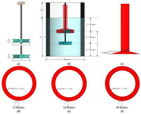
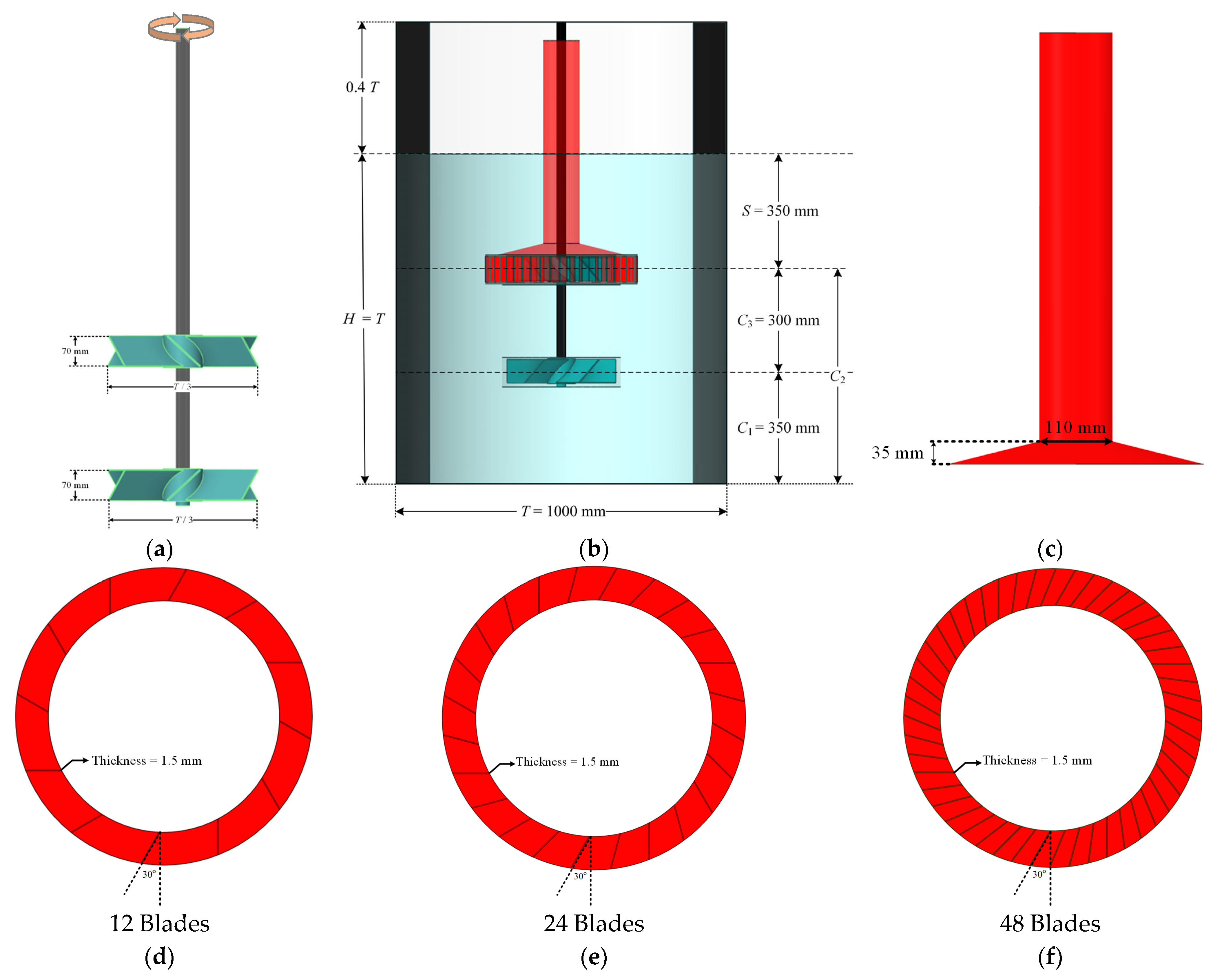
In accordance with the configuration reported by Saravanan and Joshi [13], simulations were conducted in a Type-22 double-impeller gas-inducing reactor with a diameter of 1000 mm (). The vessel was equipped with four 10 mm thick baffles, and the working liquid height was maintained equal to the diameter (). A schematic of the system is provided in Figure 1. The reactor employed a pitched blade turbine downflow (PBTD) as the upper impeller and a pitched blade turbine upflow (PBTU) as the lower impeller, enabling both efficient gas dispersion and bulk liquid circulation. The impellers were connected to a single shaft. The lower impeller was positioned with a clearance of C1 = 350 mm from the tank bottom, while the distance between the two impellers was C3 = 300 mm. The upper impeller was submerged 350 mm below the liquid surface, denoted as S. The design dimensions of the impellers are depicted in Figure 1a.
Figure 1.
Geometry of the Type-22 Gas-Inducing Reactor and Stator Designs: (a) Impellers dimensions, (b) Reactor tank and impeller spacing, (c) Standpipe dimensions, (d) 12-blade stator, (e) 24-blade stator, (f) 48-blade stator.
Following the design principles established by Raidoo et al. [14] and Zundelevich [15], three stator configurations were evaluated. Each stator featured a blade angle of 30° and a diameter of 1.4 D, with an initial blade thickness of 1.5 mm. The number of blades was systematically varied from 12 to 24 and 48. In addition, four blade thicknesses, 1.5 mm, 15 mm, 35 mm, and 45 mm, were applied to the 12-blade stator configuration to assess the influence of slot openness and hydraulic restriction on gas dispersion behavior. Variation in blade thickness modified only the circumferential slot opening between adjacent blades, while the axial slot height and overall stator geometry were kept constant. Consequently, changes in blade thickness directly altered the stator open-area fraction (ϕA) without affecting the stator height or blade angle. Variation in the number of stator blades is particularly significant, as it alters jet development and turbulence dissipation, thereby influencing gas dispersion behavior and overall gas holdup [4,8,9,10,11].
2.2. CFD Model Details
All numerical simulations were performed using a commercial CFD package ANSYS Fluent 23 R2 (ANSYS Inc., Canonsburg, PA, USA) [16]. The governing equations were solved with a pressure-based segregated solver. Pressure-velocity coupling was handled using the SIMPLE algorithm, while second-order spatial discretization was applied to the momentum and turbulence equations as well as to temporal time advancement. Convergence was assumed when residuals for continuity, momentum, and turbulence transport equations dropped below 10−4. No-slip boundary conditions were imposed on all solid surfaces. Impeller motion was represented using a transient multiple reference frame (MRF) approach, in which the computational mesh remains stationary while rotor motion is introduced through a rotating reference zone. The MRF method provides a phase-averaged representation of the rotor–stator interaction and offers a significantly lower computational cost than a sliding-mesh formulation, while still delivering acceptable and well-established accuracy for predicting time-averaged flow fields, gas holdup, and torque in mechanically agitated reactors [12,17,18,19]. A sliding-mesh (SM) approach explicitly resolves the unsteady blade-passing interaction between the impeller and stator, capturing phase-dependent jet modulation and transient peaks in shear and dissipation. These details are important for studies targeting instantaneous breakup or blade-passing dynamics, but they occur on timescales much shorter than those governing gas residence time and overall gas holdup, so their influence is largely time-averaged in design-oriented analyses. SM also requires substantially finer spatial and temporal resolution in the narrow rotor–stator gap, which markedly increases cell count and computational cost and can reduce numerical robustness. Therefore, because this work focuses on time-averaged global metrics and comparative stator-geometry effects, the MRF approach provides a practical trade-off between fidelity and computational feasibility.
A time step 10−4 was employed, ensuring Courant numbers below unity in the impeller region. All simulations were advanced until statistically steady behavior was reached. The impeller torque converged rapidly and reached a stable value after approximately 10 s of physical time. Other global and local quantities, including gas holdup, dissipation rate, and velocity fields, required longer simulation time and converged after approximately 80 s. Final reported results were extracted from the last portion of the simulations (80–100 s), during which all monitored quantities exhibited only bounded fluctuations with no systematic temporal drift.
Water and air were considered as the main phases. The physical properties of the water were set as ρwater = 998 kg·m−3 and μwater = 1.003 mPa·s. while for the air phase ρair = 1.225 kg·m−3, μair = 1.789 10−5 kg·m−1s−1.
The simulations were carried out at 240, 300, and 360 rpm impeller speeds to validate the CFD results, then set to an impeller speed of 360 rpm. A two-fluid Euler–Euler framework was employed, in which the gas phase was modelled as a dispersed secondary phase with a uniform bubble diameter of 1 mm in all simulations in line with the bubble size range of 2.0 to 8.0 mm for most of the gas–liquid reactors and GIRs [17,20]. Within this formulation, both the liquid and gas phases are treated as interpenetrating continua, and separate sets of conservation equations are solved for each phase. In contrast to multiphase CFD-DEM approaches, which increasingly enable mechanistic interrogation of complex mixing flows, the Euler–Euler method offers substantially lower computational cost while providing sufficient accuracy, with reduced reliance on extensive closure selection and calibration efforts [21,22,23,24]. The continuity and momentum balances for each phase are expressed in Equations (1) and (2) [1,17,25,26]:
In the above equations, ρi, hi, ui, and FD,i denote the density, volume fraction, velocity of phase i, and the drag force of gas bubbles. The effective Reynolds stress tensor, , is defined with respect to the time-averaged velocity according to the following relation:
where λi is the bulk viscosity, and μi and μt,i are laminar and turbulent viscosity of phase i, respectively. Turbulence closure was achieved using the realizable k–ε model with standard wall function, previously identified as the most reliable option for GIR systems of similar geometry [12,27]. C2, C3, σk, σɛ, σGL were set with default values of 1.9, 1.3, 1, 1.2, 0.75, respectively. Similar CFD studies commonly employ two-equation RANS closures with their standard constants. This turbulence model is known to perform robustly in flows with strong streamline curvature and rotation, conditions characteristic of mechanically agitated vessels.
In this study, drag was considered as the main interphase momentum exchange force, while lift and virtual mass were omitted due to their negligible influence in mechanically agitated multiphase vessels [27] and GIRs [12]. The drag force was computed as:
The standard Schiller–Naumann correlation is widely used for non-deformed spherical bubbles [1], but it underestimates the drag force under mechanically generated turbulence [12]. The empirical correction originally proposed by Brucato et al. [28] and later refined by Lane et al. [29] was therefore selected to improve predictions in stirred systems. Santos-Moreau et al. [12] evaluated several drag formulations for a Type-11 GIR, including the standard Schiller–Naumann model, the Brucato correction, the Pinelli model [30], and the Lane modification of Schiller–Naumann. Among these, the Lane modification provided the closest agreement with experimental measurements, while the Pinelli model consistently overpredicted drag, and the original Brucato correction produced unphysical behavior. A similar comparison performed for the present Type-22 system yielded the same outcome, as shown in the Results section. Consequently, the drag coefficient in this study was modelled using the Schiller–Naumann correlation with the Lane et al. [29] modification, which incorporates turbulence effects through the Kolmogorov length scale. The implementation was carried out through a user-defined function (UDF), available in our GitHub link provided at the end of the manuscript:
where db is the bubble diameter and λK the Kolmogorov scale. Here, CD is estimated by the standard Schiller–Naumann expression:
with the bubble Reynolds number defined as:
2.3. Meshing
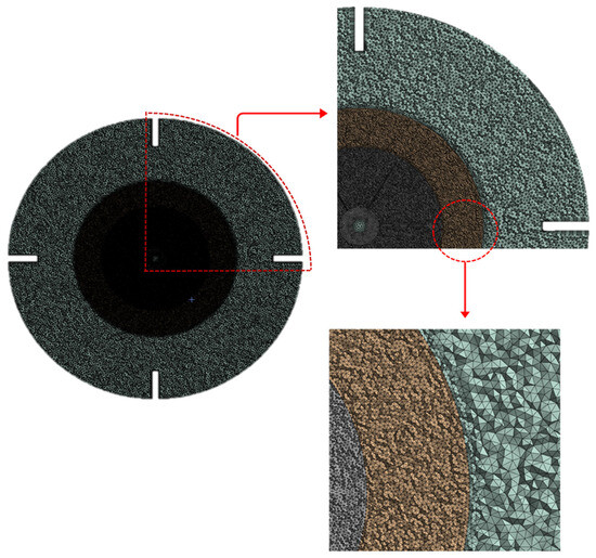
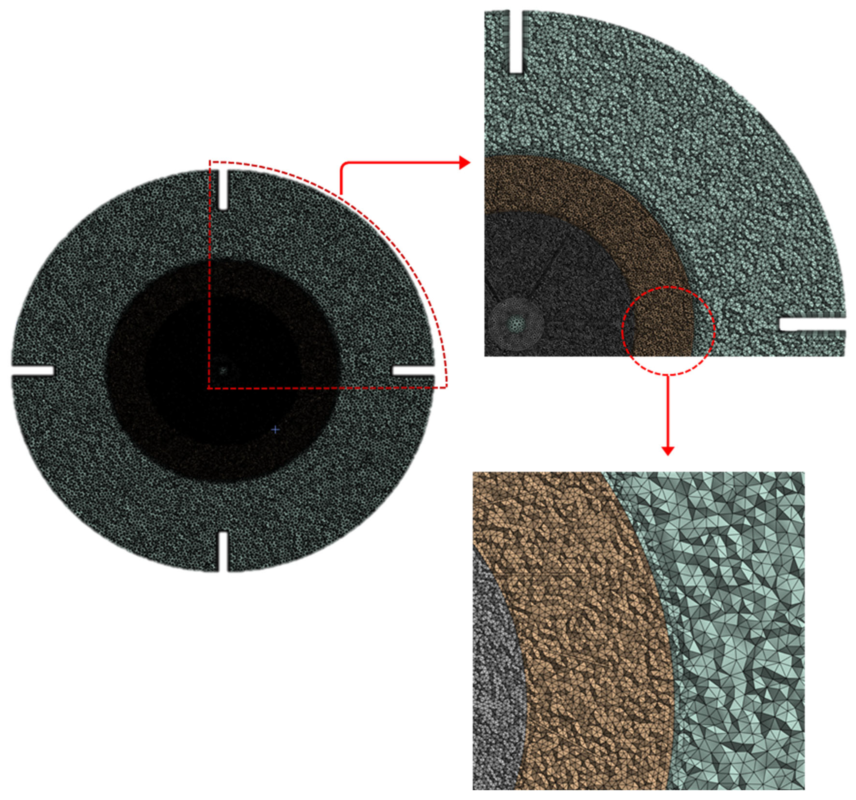
Four unstructured tetrahedral meshes containing approximately 3, 7, 15, and 27 million cells (Grids 1–4) were generated using ANSYS Meshing. Local refinements were applied within the stator slot region, where previous rotor–stator studies have documented high turbulence intensity and elevated energy dissipation near the walls [4,10,11,31,32]. All computational meshes were generated using an unstructured meshing topology composed of tetrahedral elements, with differences arising only from the overall element size to assess grid sensitivity. A cross-sectional view of the final mesh is presented in Figure 2. The computational domain consisted of five primary regions: the tank, stator slots, top impeller frame, bottom impeller frame, and the standpipe. Local mesh refinement was applied within the stator slots, impeller frames, and standpipe to resolve the high shear rates and steep turbulence gradients characteristic of these zones. The bulk tank region was meshed with relatively coarser elements to balance numerical accuracy with computational cost, while inflation layers were applied along the baffle surfaces to adequately resolve near-wall gradients.
Figure 2.
Cross-sectional view of the computational mesh with local refinement zones.
2.4. Grid Size Independence
To ensure mesh-independent results and quantify the numerical uncertainty associated with spatial discretization, the Grid Convergence Index (GCI) method proposed by Roache [33,34] and formalized by Celik et al. [25,33,35] was applied. This approach evaluates the convergence behavior of a numerical solution by systematically refining the computational grid and comparing results among three successively finer meshes. For a given monitored variable f—overall holdup and dissipation rate in this study—the relative errors between grid levels were calculated as:
where the subscripts c, b, and a refer to the coarse, medium, and fine grids, respectively. The grid refinement ratios were defined as and , where h represents the characteristic cell size. The apparent order of convergence (p) was determined iteratively from the logarithmic relationships between successive mesh refinements:
Finally, the GCI values, representing the estimated relative numerical uncertainty for each grid pair, were then computed as follows:
The solution was deemed to lie within the asymptotic convergence range when: . As four different grid sizes were used, asymptotic convergence was calculated for two pairs of three. Once this criterion was met, the GCI value corresponding to the medium mesh (GCIba) could be taken as an acceptable estimate of the numerical discretization error.
2.5. Gas Holdup Correlation
Saravanan et al. [13] proposed an empirical correlation for predicting gas holdup in a double-impeller GIR, expressed as:
where hg is the volume-averaged gas holdup, D/T is the impeller-to-tank diameter ratio, and the dimensionless group represents the balance between power input, gas flow, density, viscosity, and gravity. Although this correlation performs reasonably well, it does not include any term that accounts for stator geometry, which plays a major role in gas induction and dispersion mechanisms in rotor–stator and GIR systems. Variations in stator blade number, thickness, slot width, and slot height alter the degree of hydraulic restriction, jet confinement, local dissipation, and bulk recirculation, parameters that directly influence bubble residence time and thus gas holdup. To incorporate these geometric effects, we introduce an additional dimensionless term based on the stator open-area fraction ϕA, defined as:
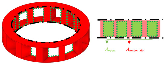
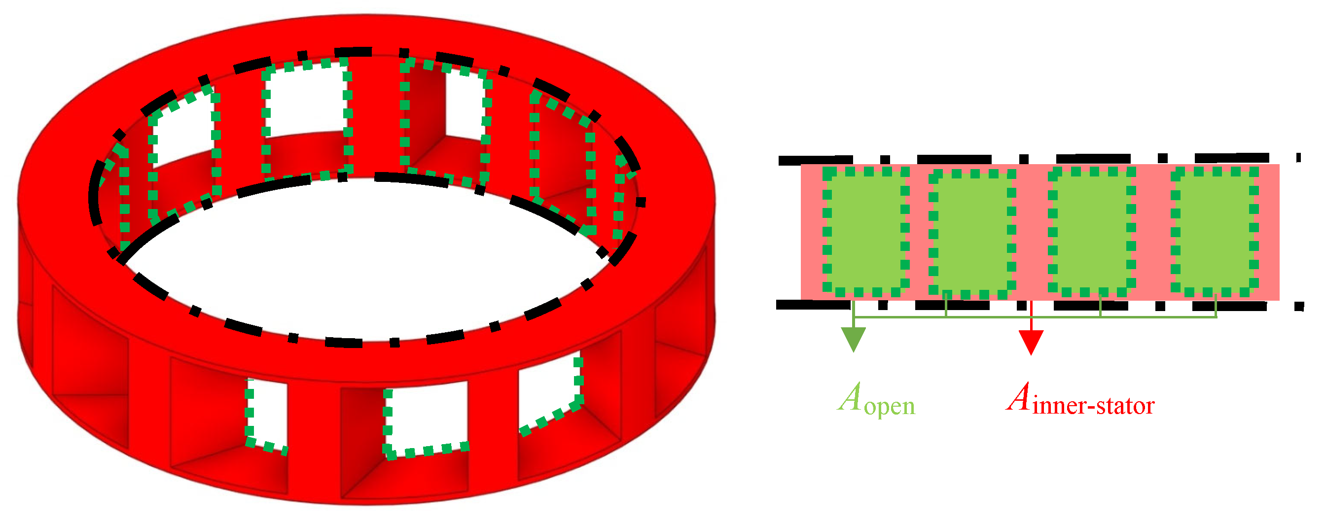
where Aopen is the total open area of all stator slots, and Ainner-stator is the inner cylindrical surface area of the stator. These areas are shown in Figure 3. This definition is physically relevant because the radial flow driven by the gas-inducing rotor passes directly through this cylindrical surface, making it the correct geometric reference area for characterizing jet development and flow restriction.
Figure 3.
3D/2D representation of the stator inner-surface and open area for a 12-blade stator with 35 mm thick blades.
To develop the extended correlation, gas holdup values were obtained from CFD simulations for several stator geometries (12-, 24-, and 48-blade stators with varying blade thicknesses). For each case, the dimensionless quantities and ϕA were computed, and a log-log multiple regression was performed on:
Since D/T remained constant in this system (D/T = 0.33), its effect was absorbed into the constant a, and only the exponents c and d were fitted. This procedure yielded a modified correlation that successfully captures the combined effects of hydrodynamics and stator geometry on global gas holdup.
3. Results
3.1. Assessment of the Mesh Independence
Grid independence was evaluated by monitoring both global and local flow metrics, overall gas holdup and dissipation rate within the stator region, along with a formal GCI analysis following Roache’s procedure [34]. These quantities were selected to ensure that mesh refinement was assessed across regions with distinctly different resolution requirements, providing a representative measure of both localized and system-wide sensitivity to grid size. The computed GCIs for all mesh pairs are summarized in Table 1. Grid 1 corresponds to the coarsest mesh, whereas Grid 4 represents the finest level of refinement. The parameters P1 and P2 in the table denote the apparent orders of spatial accuracy calculated from two independent grid triplets. Specifically, P1 is obtained from the Grid 1-Grid 2–Grid 3 sequence, while P2 is obtained from the Grid 2–Grid 3–Grid 4 sequence. These values quantify how rapidly the solution changes with mesh refinement and are used to assess whether the numerical solution exhibits consistent convergence behavior.
Table 1.
GCI calculations.
The results indicate that Grids 2, 3, and 4 lie within the asymptotic convergence range (closer to 1), demonstrating consistent grid-refinement behavior, whereas Grid 1 falls outside this range and is therefore insufficiently resolved. The asymptotic ratios compare the observed convergence behavior against the theoretical asymptotic range; values approaching unity indicate that the solution has entered the asymptotic convergence regime, where discretization errors decrease in a predictable manner and further refinement yields diminishing returns. Based on these criteria, Grid 3 was selected because it already lies within, or very close to, the asymptotic convergence range for both overall gas holdup and stator-zone dissipation rate. Refinement from Grid 3 to Grid 4 results in only marginal changes. These differences do not affect the observed trends or the physical interpretation of the results. Consequently, Grid 3 represents the most appropriate mesh, providing sufficient numerical accuracy and robustness without unnecessary calculation expenses.
Among the asymptotically converged meshes, Grid 3, with 15,369,452 elements, provides an optimal balance between accuracy and computational cost. Furthermore, the resulting dimensionless wall distance, y+, remained below 300 throughout the domain and was predominantly within the range 40 ≤ y+ ≤ 300, which is appropriate for standard wall-function treatments in high-Reynolds-number stirred tank simulations. The reported y+ range corresponds to wall-adjacent cells on baffles, tank wall, and stator surfaces in the Grid 3 settings. Thus, this grid setting was selected for all simulations conducted in this study.
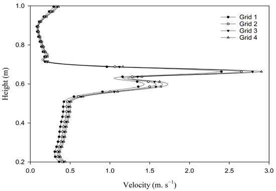
Figure 4 presents velocity profiles along a vertical line located midway between the stator and the baffle, a region influenced by both impeller-induced jets and bulk recirculation for the 12-blade stator design. The close agreement among the profiles for the refined meshes indicates that the predicted local velocity field is insensitive to further mesh refinement, providing additional confirmation of hydrodynamic convergence.
Figure 4.
Velocity profiles along the stator–baffle midplane for different mesh resolutions for 12-blade stator.
3.2. Model Validation
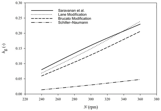
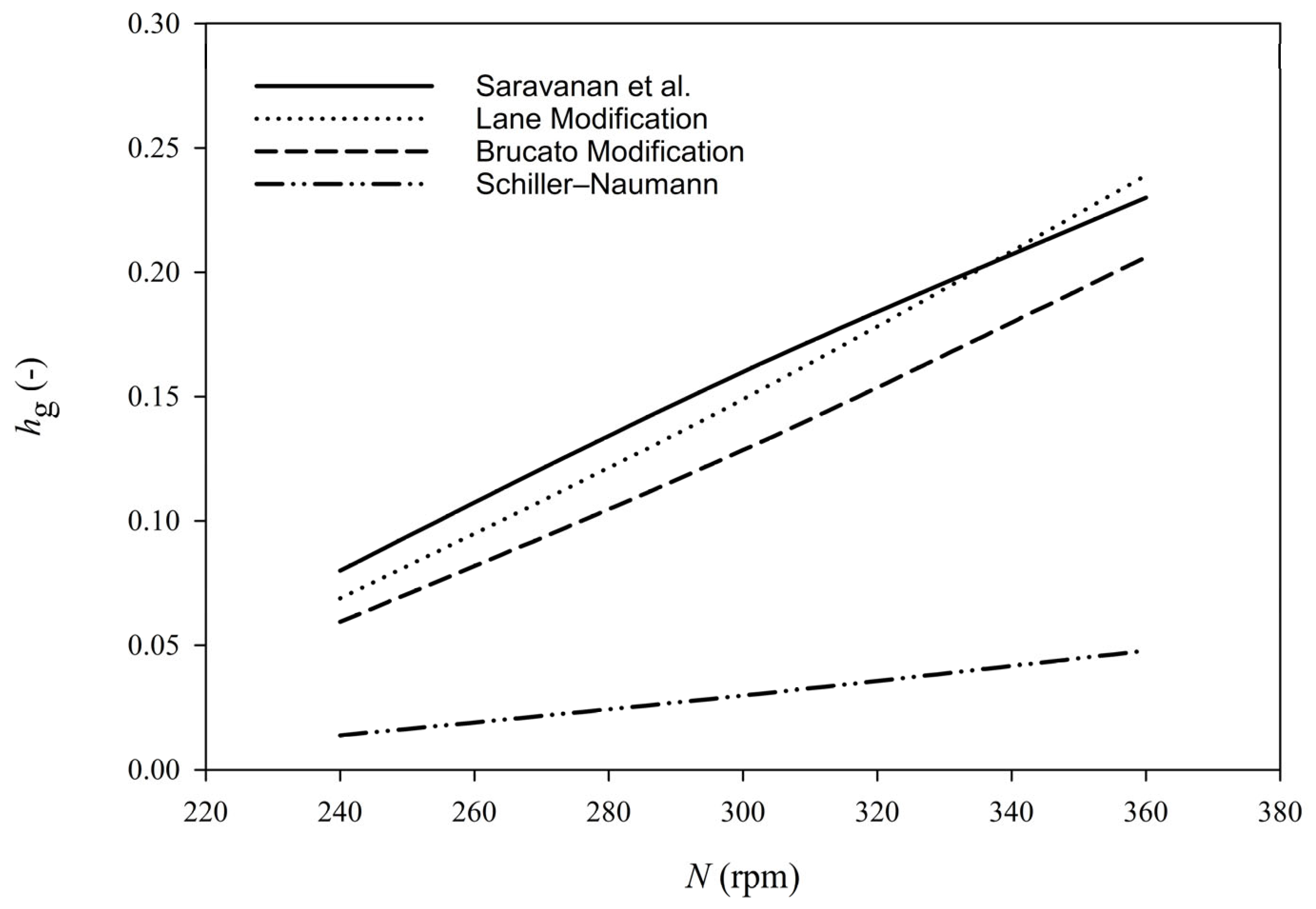
CFD validation was carried out by comparing the predicted gas holdup () with the experimental measurements reported by Saravanan et al. [13] at impeller speeds of 240, 300, and 360 rpm (Figure 5). The CFD results reproduced the correct increasing trend of gas holdup with rotational speed and matched the experimental data with good accuracy. At 240 rpm, the deviation between CFD and experiment was approximately 8–10%, while the errors at 300 rpm and 360 rpm were reduced to 5–7% and 6–8%, respectively. These deviations fall within the typical range reported for Euler–Euler simulations of gas–liquid stirred tanks, confirming that the dominant gas-dispersion mechanisms were captured effectively. It is worthwhile noting that the standard Schiller–Naumann drag model and the Schiller–Naumann model with the Brucato turbulence correction both produced significantly larger errors and failed to predict the correct magnitude of gas holdup across all operating speeds. The results presented here correspond to the Lane et al. drag modification, which provided the closest agreement with Saravanan et al.’s experimental data and offered a physically consistent representation of bubble–liquid momentum exchange under the high-shear conditions generated by the gas-inducing impeller. The strong agreement obtained using the Lane et al. correction validates the CFD framework and supports its use for subsequent analysis of stator geometry effects on gas holdup.
Figure 5.
Validation of CFD gas holdup predictions against Saravanan et al. [13] using different drag models.
While the remaining deviations can be attributed primarily to the simplified treatment of bubble size, neglecting dynamic breakup–coalescence processes and free-surface entrainment simplification, which are known to influence gas holdup under high-shear gas-inducing conditions. This level of agreement indicates that the assumed effective bubble diameter of 1 mm provides a reasonable representation of gas–liquid interaction for the present operating system. However, a more detailed treatment of bubble size distributions would require dedicated experimental measurements and is beyond the scope of this study. The assumed bubble diameter should be interpreted as an effective modeling parameter rather than a uniquely defined physical bubble size. In gas-inducing reactors, the bubble population is inherently polydisperse and continuously evolving due to intense shear, repeated passage through the rotor–stator region, breakup, and coalescence. In the absence of direct bubble size measurements for the present configuration, a uniform diameter was adopted to represent the dominant interphase momentum exchange within the Euler–Euler framework. The choice of 1 mm reflects the expectation of relatively small bubbles under high-shear gas-inducing conditions, while acknowledging that larger effective diameters may occur depending on operating conditions.
3.3. Impact of Blade Thickness and Number of Blades
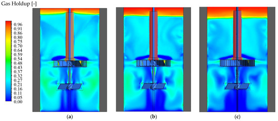
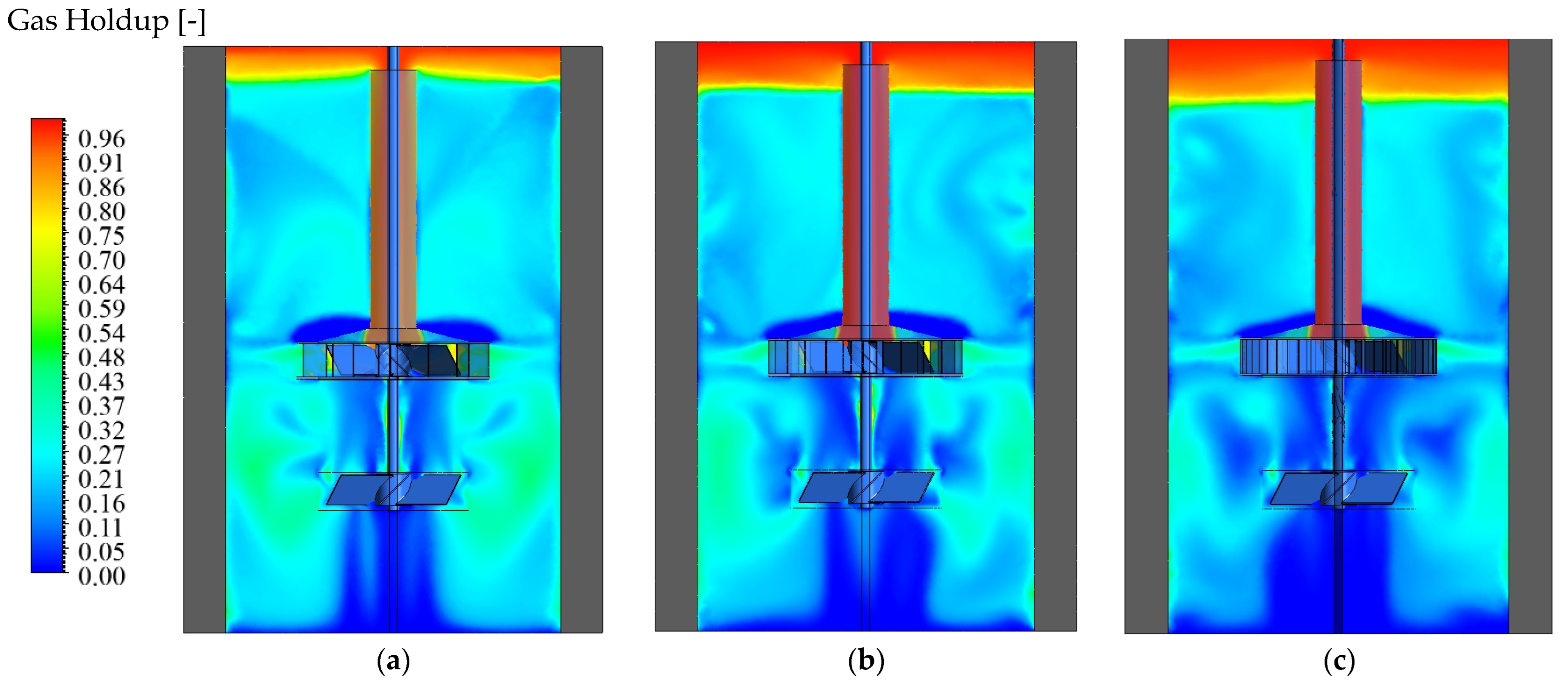
Figure 6 shows the vertical air-volume-fraction fields for the GIR system with 12-, 24-, and 48-blade stators, and highlights how the gas plume shape changes as the stator becomes denser. With 12 blades, the gas jet leaving the gas-inducing rotor spreads widely into the surrounding liquid. This creates a broad gas plume and strong radial dispersion, along with large recirculating regions above and below the stator. Because bubbles are repeatedly entrained into these circulation zones, their residence time increases, resulting in a relatively high overall gas holdup. When the number of blades increases to 24, the jet becomes more confined. The stator provides additional blockage, which limits lateral spreading and weakens the large recirculation structures that were prominent in the 12-blade case. As a result, the gas column becomes narrower and more symmetrical. With 48 blades, this effect becomes much stronger. The gas plume becomes very thin and elongated, and the gas moves almost straight upward with minimal radial motion.
Figure 6.
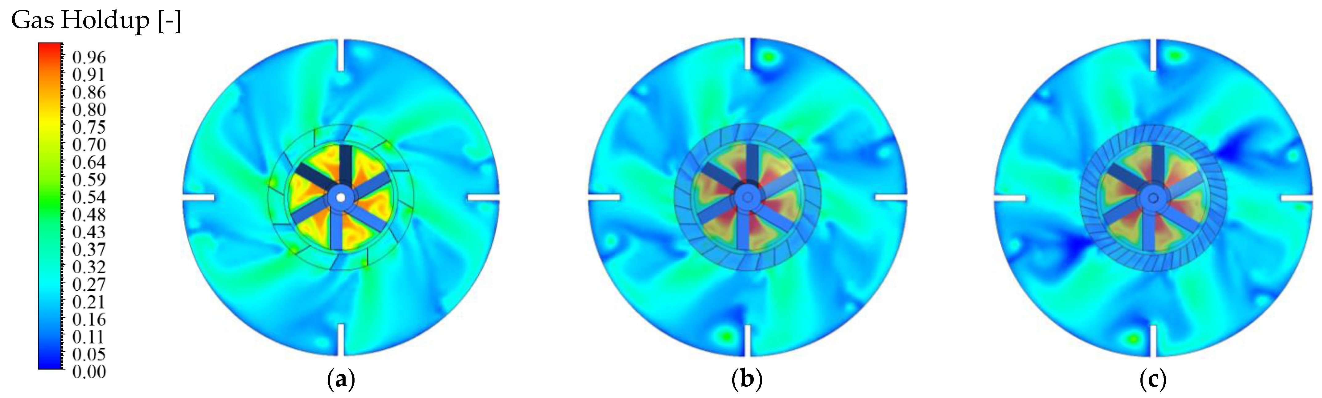
Axial cross-sectional distribution of gas holdup: (a) 12-Blade Stator, (b) 24-Blade Stator, and (c) 48-Blade Stator.
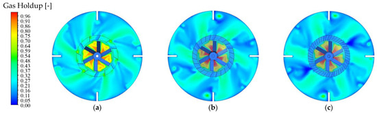
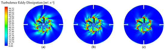
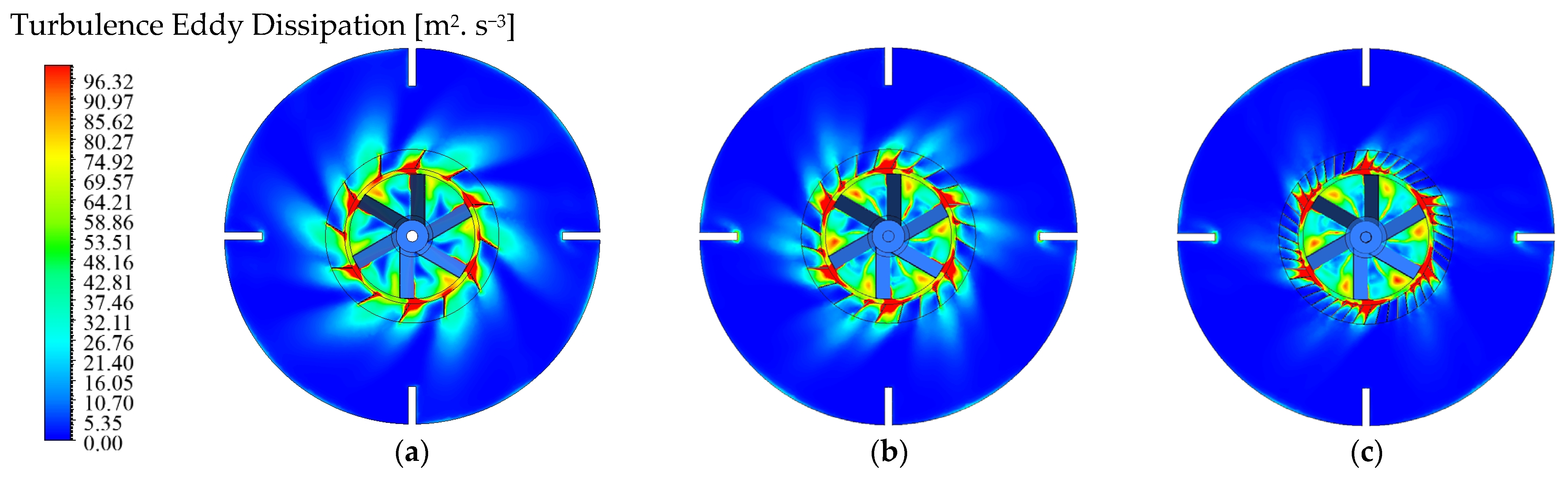
Figure 7 shows the horizontal air-volume-fraction fields and confirms the same trend observed in the vertical sections: gas occupies a wide region around the impeller with 12 blades, becomes more restricted with 24 blades, and is confined almost entirely within the stator circumference when 48 blades are used. Despite the 48-blade stator producing the strongest and most focused jet, the overall gas holdup decreases as blade number increases. This counterintuitive behavior arises from two competing mechanisms. On one hand, adding more blades intensifies local shear and increases turbulence within the stator openings. On the other hand, and more importantly, the denser stators restrict radial flow, weaken large-scale circulation, and channel bubbles upward more directly, thereby shortening their residence time and promoting rapid disengagement at the free surface. Similar competing effects between localized dissipation and bulk recirculation have been reported for rotor–stator systems with narrow or numerous openings [4,8,9,10,11]. The turbulence eddy-dissipation fields in Figure 8 further support this interpretation. As the blade number increases, turbulent dissipation becomes highly localized within the rotor–stator gap and along the blade edges, whereas the 12-blade configuration spreads dissipation more broadly into the surrounding fluid. Although the Euler–Euler model does not capture bubble breakup, the dissipation distribution reveals how momentum is transferred into the bulk and how recirculation structures are sustained. In the 12-blade stator, dissipation extends radially outward, driving strong jets and large recirculation loops that repeatedly re-entrain gas and increase residence time. In contrast, the 24- and 48-blade stators confine dissipation to a narrow annulus, producing jets that rapidly lose momentum and fail to generate substantial radial mixing. The resulting flow field becomes strongly axial, allowing gas to escape quickly. Consequently, even though denser stators exhibit higher local dissipation, the suppression of radial flow and recirculation dominates the global hydrodynamics, leading to more efficient gas transport to the free surface and a reduction in overall holdup.
Figure 7.
Radial cross-sectional distribution of gas holdup: (a) 12-Blade Stator, (b) 24-Blade Stator, and (c) 48-Blade Stator.
Figure 8.
Turbulence eddy dissipation: (a) 12-Blade Stator, (b) 24-Blade Stator, and (c) 48-Blade Stator.
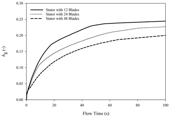
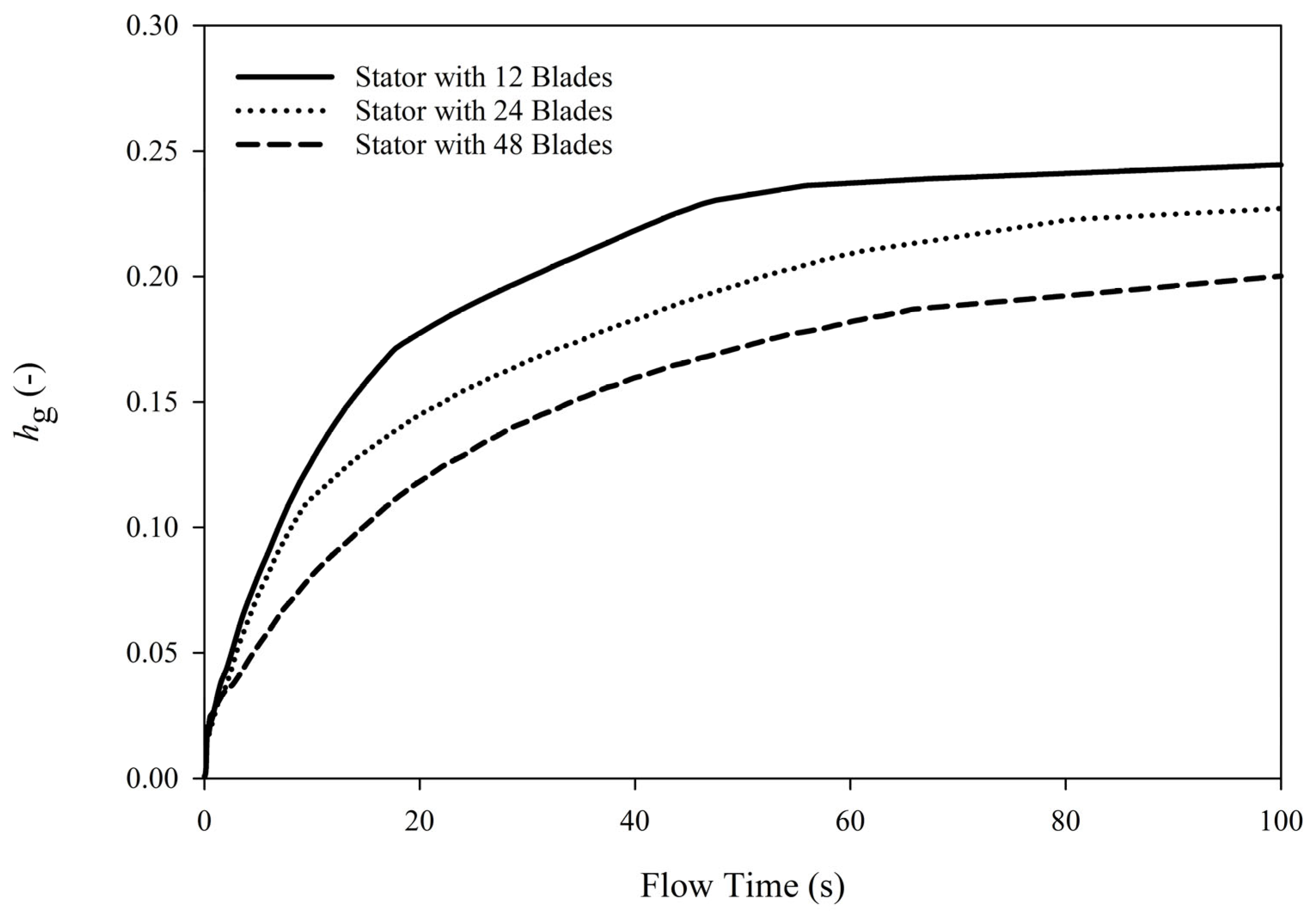
Taken together, the holdup versus time results in Figure 9 further confirm this interpretation. The 12-blade stator, which generates the strongest radial spreading and the most persistent recirculation loops, exhibits the highest gas holdup throughout the mixing period due to prolonged bubble residence time. Increasing the blade count to 24 reduces both the magnitude and duration of recirculation, causing bubbles to rise and escape more quickly and lowering the overall holdup. This trend becomes even more pronounced with 48 blades, where the jet is highly confined and the flow becomes strongly axial, producing the lowest holdup of all configurations. The temporal evolution in Figure 9 is therefore fully consistent with the contour fields shown in Figure 1, Figure 2 and Figure 3.
Figure 9.
Gas holdup changes versus flow time for stators with different blade numbers.
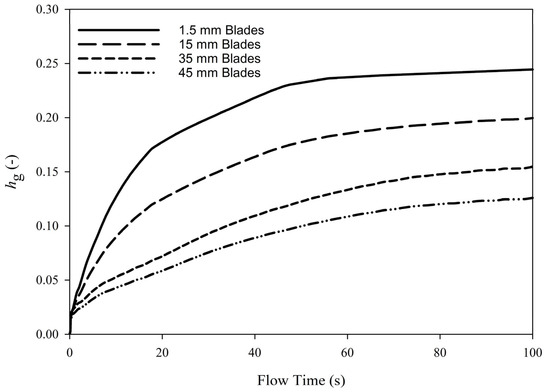
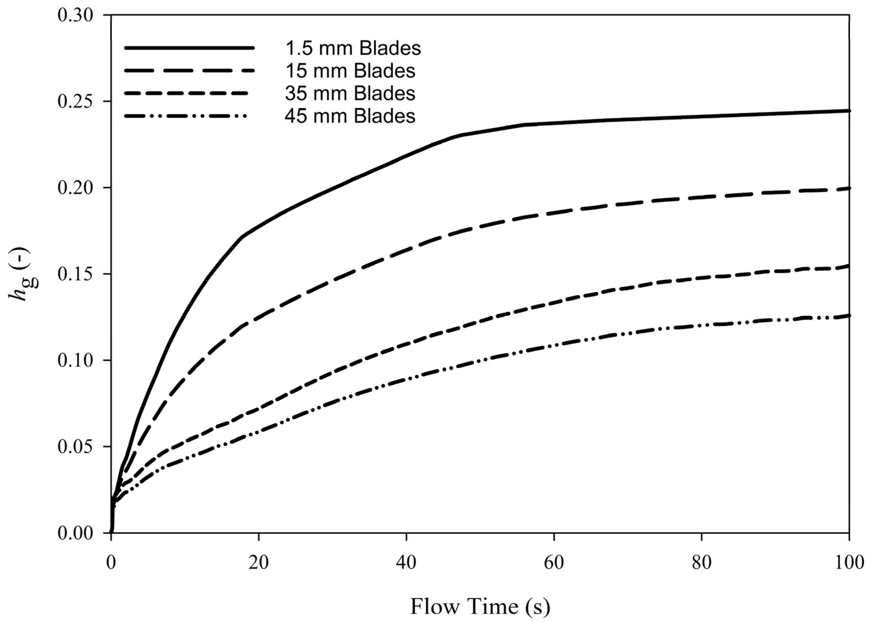
A similar pattern emerges when considering blade thickness, as shown in Figure 10. Thin blades permit broader radial dispersion and support stronger recirculation structures that retain bubbles within the mixing zone. As blade thickness increases, the stator openings become more restrictive, radial flow weakens, and recirculation progressively collapses. Consequently, bubbles are transported upward more efficiently, residence time decreases, and the overall gas holdup declines. The holdup trends in Figure 10 therefore reinforce the same physical mechanism observed for blade number: stator geometries that promote flow confinement and suppress bulk recirculation inevitably shorten bubble residence time and reduce gas holdup, even when local turbulence levels remain high.
Figure 10.
Gas holdup changes versus flow time for different stator blade widths.
While the present results are based on an air–water system, the implications become even more significant when the working fluid exhibits non-Newtonian rheology. In shear-thinning liquids, viscosity increases sharply in low-shear regions, precisely where recirculation is required to transport bubbles away from the impeller zone and sustain dispersion. As a result, any reduction in radial flow or collapse of circulation structures is amplified by the fluid’s shear dependence; bulk circulation weakens further, and bubbles are transported upward more rapidly. This coupling between flow confinement and rheology can therefore intensify the decline in gas holdup observed with dense stator geometries. To mitigate these effects, mixing strategies that deliberately strengthen macro-circulation are required. Pairing the high-speed inner impeller with a slow-moving anchor can provide this capability by promoting vessel-wide motion and maintaining a more uniform shear field, making such coaxial configurations a promising alternative for gas dispersion in self-inducing systems containing non-Newtonian media [36,37].
3.4. Derivation of Gas Holdup Correlation
Gas holdup values obtained from CFD clearly demonstrate that stator geometry, particularly slot openness and blade thickness, strongly influences both local flow structures and global gas retention. Cases with thin blades and large slot openings (high ϕA) exhibited broader radial gas dispersion, stronger recirculation zones, and longer bubble residence times, resulting in higher volume-averaged gas holdup. In contrast, dense stators with thick blades or a large number of blades (low ϕA) created substantial hydraulic restriction, narrowing the slot jets, directing the gas plume axially, and reducing bulk recirculation. Although these configurations exhibited stronger local jet velocities and higher local shear rates within the stator openings, the reduced recirculation caused bubbles to escape to the free surface more rapidly, leading to lower global holdup.
When the measured holdup values were correlated using the original Saravanan dimensionless group , the data showed only partial collapse and considerable scatter, largely because the formulation does not account for differences in stator geometry. Introducing the stator open-area fraction significantly improved the correlation, and regression of the experimental data yielded the fitted parameters a = 0.0904, c = 0.373, and d = 0.381, with an overall coefficient of determination R2 = 0.957. This strong agreement demonstrates that the additional stator-dependent term effectively captures the holdup variability arising from changes in stator configuration. The resulting CFD-derived modified GIR–stator correlation is:
Above was developed in dimensionless form, and its applicability is therefore governed by the preservation of the dominant hydrodynamic balances embedded in the governing dimensionless groups, rather than by absolute reactor size alone. Accordingly, the correlation is expected to perform well for gas-inducing reactors operating within regimes where stator-induced confinement remains the controlling mechanisms for gas retention, and where the stator open-area fraction ϕA continues to represent the primary geometric constraint on radial gas escape. Degradation in predictive accuracy is expected when the relative importance of these mechanisms changes. This may occur at very low or very high ϕA, where the flow transitions, respectively, toward strong axial confinement or near-unrestricted radial discharge, altering the assumed coupling between jet penetration, recirculation, and gas residence time. Similarly, operating regimes characterized by low Reynolds numbers, intermittent or unstable gas induction, or bubble dynamics dominated by coalescence or breakup rather than turbulent dispersion may not be fully captured by the present formulation. Under such conditions, the correlation may still reproduce qualitative trends but would require reassessment before quantitative application.
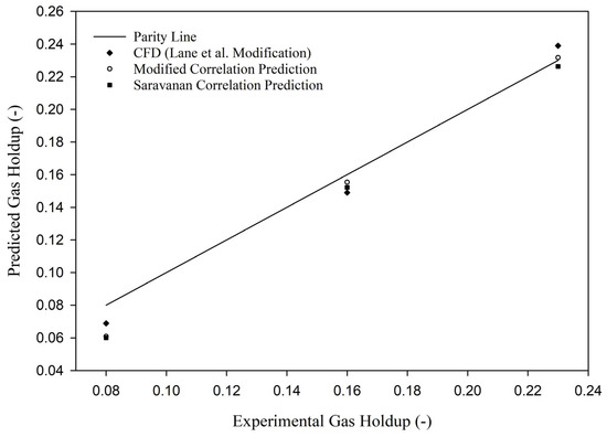
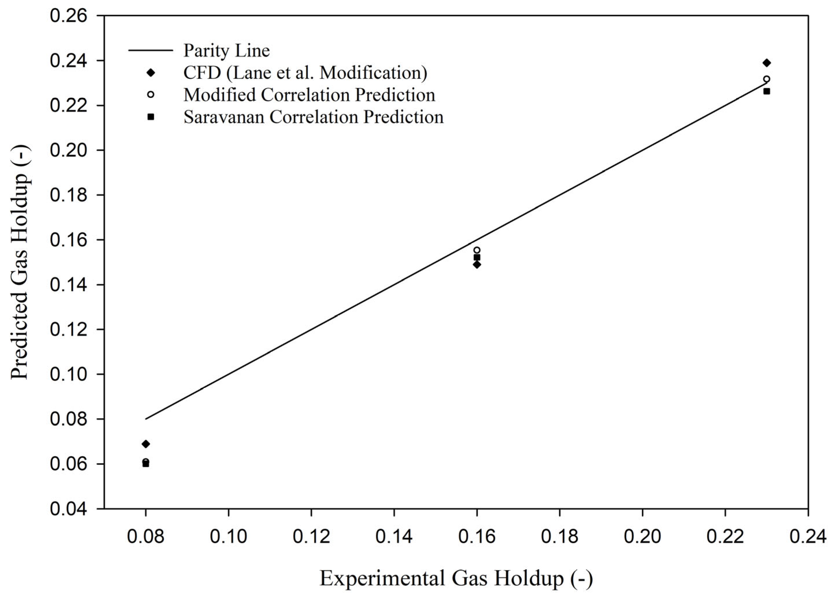
Figure 11 presents a parity comparison between predicted and experimentally measured overall gas holdup. Experimental data reported by Saravanan et al. are used as the reference, while predictions from CFD simulations employing the Lane et al. drag modification, the original Saravanan-type correlation refitted to the present dataset, and the modified correlation proposed in this study are compared directly against the parity line. All approaches capture the monotonic increase in gas holdup with increasing impeller speed, indicating consistent representation of the dominant gas induction and dispersion mechanisms.
Figure 11.
Parity plot comparing predicted and experimental overall gas holdup: CFD (Lane et al. modification), refitted Saravanan correlation, and modified correlation proposed in this study.
At 240 rpm, the experimental gas holdup is approximately 0.080. The CFD prediction underestimates this value by about 14% (≈0.069). The Saravanan correlation, refitted in the reduced form to account for the fixed D/T ratio in the present geometry, underpredicts the experimental value by approximately 25% (≈0.060). The modified correlation improves the prediction, reducing the deviation to approximately 20% (≈0.064), although discrepancies remain at low impeller speeds where gas induction is weaker and more sensitive to local flow structures.
At 300 rpm, the experimental gas holdup increases to approximately 0.160. The CFD prediction deviates by about 6%, while both the refitted Saravanan correlation and the modified correlation show comparable deviations of approximately 4–6%, demonstrating significantly improved agreement in the fully turbulent regime. At this operating condition, the modified correlation closely follows the CFD trend, indicating consistency between the correlation-based and CFD-based descriptions of gas holdup.
At 360 rpm, all predictive approaches converge further toward the experimental data. The CFD prediction slightly overestimates the experimental gas holdup by approximately 4–5%, whereas the refitted Saravanan correlation underpredicts it by about 2–3%. The modified correlation yields the closest agreement, with a deviation within 2% of the experimental measurement.
Overall, refitting the Saravanan et al. correlation using the combined coefficient a* and exponent ccc enables a fair comparison under the present fixed-geometry conditions. The modified correlation consistently reproduces both the trend and magnitude of the experimental and CFD results across the investigated range, with deviations generally within 2–6% at moderate to high impeller speeds. This improved agreement highlights the benefit of explicitly incorporating stator-related effects while remaining consistent with established GIR scaling behavior, supporting the use of the modified correlation as a practical predictive tool within the validated operating range.
3.5. Torque Fluctuations
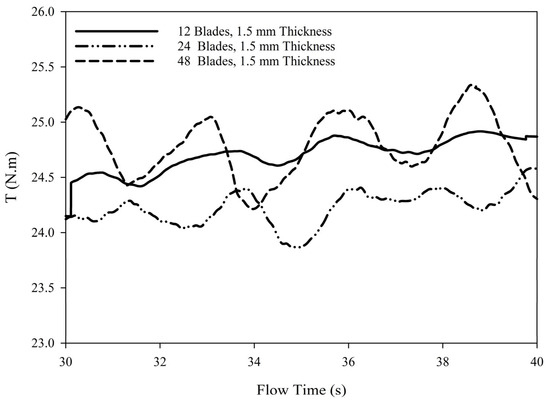
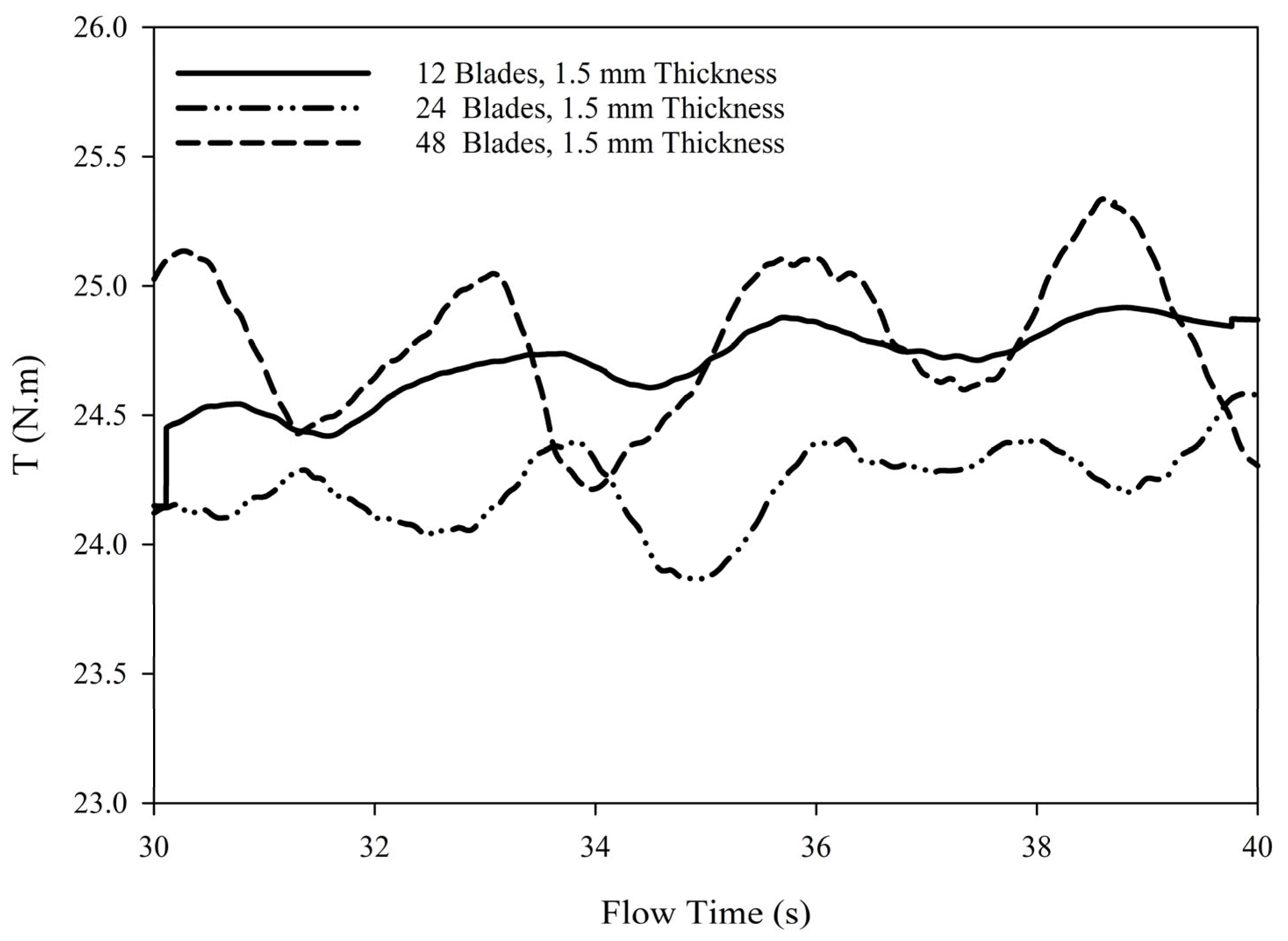
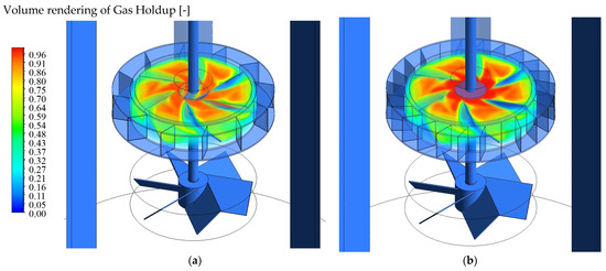
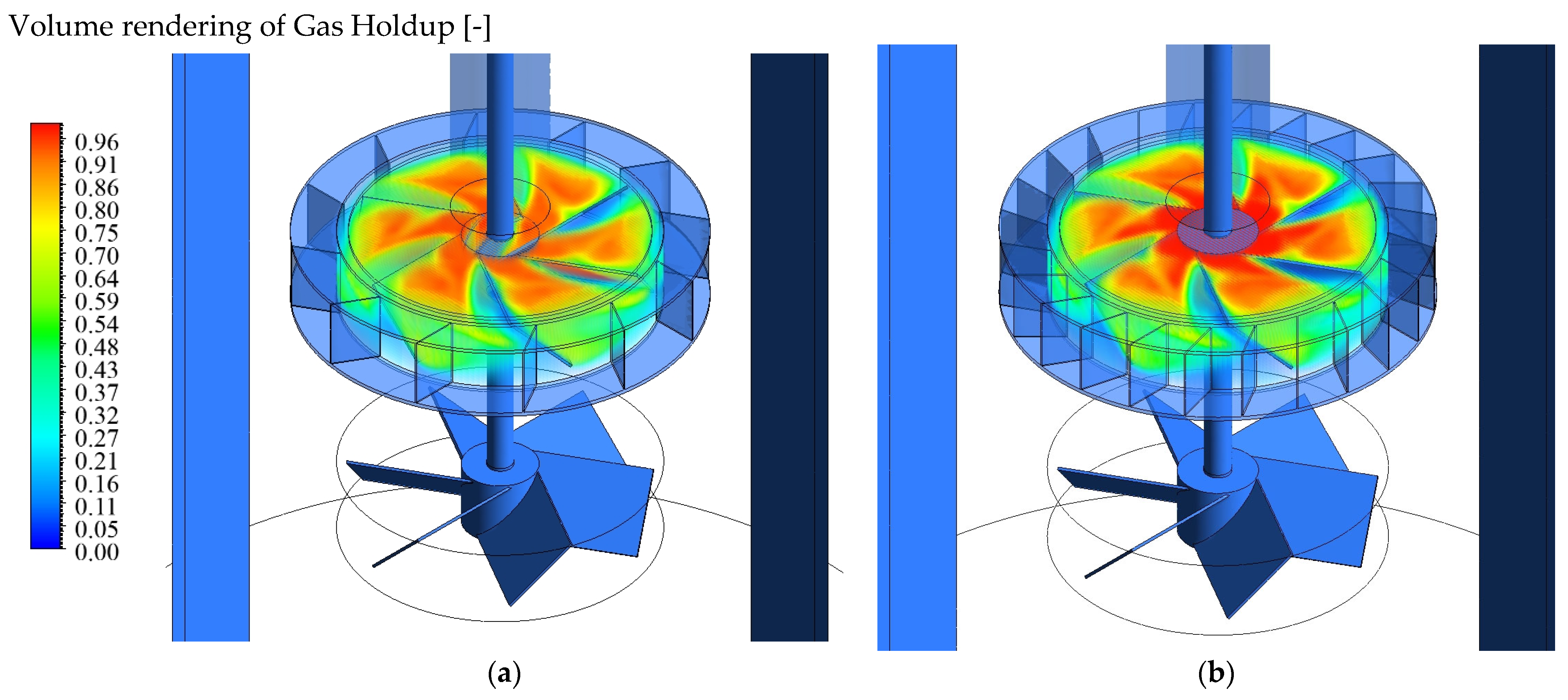
Consistent with the observations of Mortensen et al. [4,10,11], who showed that power number and flow characteristics in rotor–stator systems are highly sensitive to stator geometry, the torque measurements of our study also reveal distinct and geometry-dependent behaviors when either blade thickness or blade number varies. Figure 12 illustrates how torque fluctuations evolve as the number of stator blades is increased from 12 to 24 and 48 at constant blade thickness. Moving from 12 to 24 blades leads to a reduction in average torque, even though the stator becomes geometrically denser. This counterintuitive trend reflects the formation of a larger and more stable gas cavity within the impeller-stator zone. As shown in Figure 13, the formation of gas pallets behind the impeller is slightly stronger for 24-blade stator, which reduces the effective liquid loading on the rotor and diminishes the mechanical resistance it experiences. However, when the blade count is further increased to 48, the torque rises sharply and exhibits stronger oscillations. At this stage, the stator becomes sufficiently restrictive for the dominant effect to shift from cavity formation to a pronounced decrease in open-area fraction, which significantly increases pressure drop and flow resistance. Thus, the torque behavior results from the competition between impeller gassing, which lowers torque, and severe flow restriction due to reduced ϕA, which increases torque.
Figure 12.
Effect of stator blade number on impeller torque fluctuations.
Figure 13.
Gas holdup volume rendering: (a) 12-Blade Stator, (b) 24-Blade Stator.
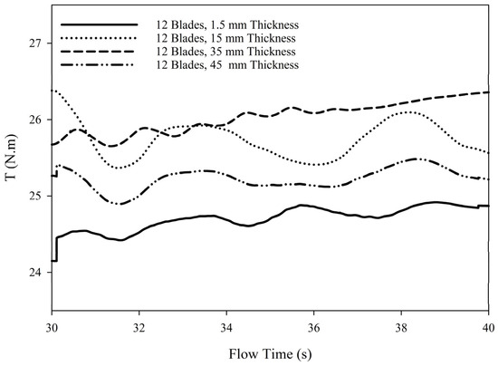
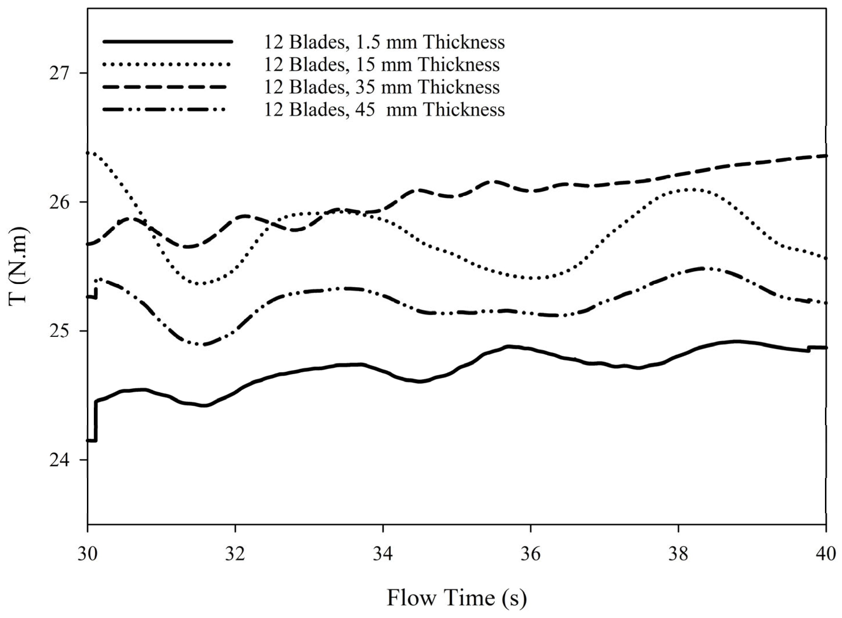
Figure 14 highlights the influence of blade thickness on torque behavior within the 12-blade stator configuration. As the blade thickness increases from 1.5 mm to 45 mm, both the mean torque and the amplitude of torque oscillations rise. This occurs because thicker blades markedly reduce the slot open area, forcing the liquid–gas mixture through increasingly confined passages. The resulting increase in pressure drops across the stator, and together with enhanced viscous and turbulent losses along the thicker blade surfaces, produces a stronger hydrodynamic load on the rotor. These conditions also intensify vortex shedding at the slot exits, giving rise to the larger periodic fluctuations observed in the torque signal. Overall, the torque response for increasing blade thickness is governed primarily by hydraulic restriction and increased flow resistance, which consistently elevate the mechanical load on the impeller.
Figure 14.
Effect of stator blade thickness on impeller torque fluctuations.
Overall, the observed torque behavior reflects a balance between two competing mechanisms: impeller gassing, which reduces torque by decreasing the effective liquid loading on the rotor, and flow restriction associated with reduced open-area fraction (ϕA), which increases torque by elevating hydraulic resistance. For thin stator blades, cavity formation and impeller gassing exert a noticeable influence, leading to lower torque, despite geometric confinement. In contrast, when the blades become thicker, the dominant effect shifts to the reduced open area of the stator, underscoring the critical role of the area ratio ϕA in determining the mechanical load on the impeller.
4. Conclusions
A transient three-dimensional Euler–Euler CFD model was developed for a Type-22 gas-inducing reactor and successfully validated against the gas holdup data of Saravanan and Joshi over a range of impeller speeds, using the realizable k–ε turbulence model and the Lane-modified Schiller–Naumann drag law. Grid Convergence Index analysis confirmed that the selected mesh provided mesh-independent predictions with acceptable numerical uncertainty.
The simulations showed that stator blade number and blade thickness strongly affect both local hydrodynamics and global gas retention. Stators with fewer, thinner blades and larger slot openings (high ϕA) promoted wide radial dispersion, strong recirculation, and longer bubble residence times, resulting in higher gas holdup. In contrast, dense stators with many or thick blades (low ϕA) confined the plume, suppressed bulk recirculation, and produced strong axial flow, which accelerated bubble escape and reduced holdup despite elevated local dissipation near the rotor–stator gap. Torque analysis revealed that the observed trends arise from a competition between impeller gassing, which lowers torque by reducing liquid loading, and increasing hydraulic restriction as ϕA decreases, which raises torque through higher pressure drop and viscous losses.
Based on the CFD-derived and experimentally validated holdup data, Saravanan’s original gas holdup correlation was extended by explicitly incorporating the stator open-area fraction. This modified correlation captures the coupled effects of operating conditions and stator geometry and provides a practical, design-oriented framework for predicting gas holdup in gas-inducing reactors within the validated geometric and operating envelope.
Future work should focus on extending this framework beyond the present air–water system and fixed geometry. In particular, incorporating non-Newtonian rheology, dynamic bubble size distributions, and alternative impeller–stator configurations, such as coaxial systems designed to restore macro-circulation under highly restrictive stator conditions, would enable broader generalization of the proposed correlation and further improve its applicability to industrial gas-inducing reactor design.
Author Contributions
E.Z.A.: Writing—original draft, Methodology, Investigation, Formal analysis, Conceptualization; F.E.-M. Writing—review & editing, Supervision, Resources, Project administration, Methodology, Funding acquisition, Conceptualization; A.L.: Writing—review & editing, Supervision, Resources, Project administration, Methodology, Funding acquisition, Conceptualization. All authors have read and agreed to the published version of the manuscript.
Funding
The financial support of the Natural Sciences and Engineering Research Council of Canada (NSERC) (RGPIN-2019-04644; RGPIN-2019-05644.) is gratefully acknowledged.
Data Availability Statement
The user-defined function (UDF) implementing the Lane et al. modification of the Schiller–Naumann drag model is available through the GitHub repository: https://github.com/ehsanzamanai/Lane-Modified-Schiller-Naumann-UDF. (accessed on 15 January 2026).
Conflicts of Interest
The authors declare no conflicts of interest.
Abbreviations
| CFD | Computational Fluid Dynamics |
| DEM | Discrete Element Method |
| GIR | Gas-Inducing Reactor |
| HSM | High-Shear Mixer |
| RSM | Rotor–Stator Mixer |
| MRF | Moving Reference Frame |
| PBTD | Pitched Blade Turbine Downflow |
| PBTU | Pitched Blade Turbine Upflow |
| UDF | User-Defined Function |
| GCI | Grid Convergence Index |
| SST | Shear Stress Transport |
| PIV | Particle Image Velocimetry |
| Greek Symbols: | |
| ρi | Density of phase i [kg·m−3] |
| μi | Laminar viscosity of phase i [Pa·s] |
| μt,i | Turbulent viscosity of phase i [Pa·s] |
| ϕA | Stator open-area fraction [-] |
| λi | Bulk viscosity [Pa·s] |
| ε | Turbulent kinetic energy dissipation rate [m2·s−3] |
| τeff | Effective Reynolds stress tensor [Pa] |
| English Symbols: | |
| Aopen | Total open area of stator slots [m2] |
| Ainner-stator | Inner cylindrical surface area of stator [m2] |
| C1 | Clearance between lower impeller and tank bottom [m] |
| C3 | Spacing between two impellers [m] |
| CD | Drag coefficient [-] |
| D | Impeller diameter [m] |
| db | Bubble diameter [m] |
| f | General monitored variable [-] |
| g | Gravitational acceleration [m·s−2] |
| h | Characteristic mesh size [m] |
| hg | Gas holdup [-] |
| hi | Volume fraction of phase i [-] |
| N | Impeller rotational speed [s−1] |
| P | Power [W] |
| Qg | Gas flow rate [m3·s−1] |
| Reb | Bubble Reynolds number [-] |
| S | Submergence depth of upper impeller [m] |
| T | Tank diameter [m] |
| ui | Velocity of phase i [m·s−1] |
References
- Abyaneh, E.Z.; Ein-Mozaffari, F.; Lohi, A. Critical Review of Gas–Liquid Mixing Using Gas-Inducing Impellers: Modeling, CFD Simulation, and ANN Applications. Ind. Eng. Chem. Res. 2024, 63, 15325–15350. [Google Scholar] [CrossRef] [Scilit]
- Adrian, R.J. Particle-imaging techniques for experimental fluid mechanics. Annu. Rev. Fluid Mech. 1991, 23, 261–304. [Google Scholar] [CrossRef]
- Atiemo-Obeng, V.A.; Calabrese, R.V. Rotor–stator mixing devices. In Handbook of Industrial Mixing: Science and Practice; John Wiley & Sons, Inc.: Hoboken, NJ, USA, 2003; pp. 479–505. [Google Scholar]
- Mortensen, H.H.; Calabrese, R.V.; Innings, F.; Rosendahl, L. Characteristics of batch rotor–stator mixer performance elucidated by shaft torque and angle resolved PIV measurements. Can. J. Chem. Eng. 2011, 89, 1076–1095. [Google Scholar] [CrossRef] [Scilit]
- Knight, P.; Instone, T.; Pearson, J.; Hounslow, M. An investigation into the kinetics of liquid distribution and growth in high shear mixer agglomeration. Powder Technol. 1998, 97, 246–257. [Google Scholar] [CrossRef] [Scilit]
- Vashisth, V.; Kumar, V. Effect of stator geometries on flow fields and mixing performance for viscous fluids. Chem. Eng. Chem. Eng. Process.-Process Intensif. 2022, 180, 108595. [Google Scholar] [CrossRef] [Scilit]
- Vashisth, V.; Nigam, K.; Kumar, V. Design and development of high shear mixers: Fundamentals, applications and recent progress. Chem. Eng. Sci. 2021, 232, 116296. [Google Scholar] [CrossRef] [Scilit]
- Zhang, J.; Xu, S.; Li, W. High shear mixers: A review of typical applications and studies on power draw, flow pattern, energy dissipation and transfer properties. Chem. Eng. Process.-Process Intensif. 2012, 57–58, 25–41. [Google Scholar] [CrossRef] [Scilit]
- Utomo, A.; Baker, M.; Pacek, A. The effect of stator geometry on the flow pattern and energy dissipation rate in a rotor–stator mixer. Chem. Eng. Res. Des. 2009, 87, 533–542. [Google Scholar] [CrossRef] [Scilit]
- Mortensen, H.H.; Innings, F.; Håkansson, A. The effect of stator design on flowrate and velocity fields in a rotor-stator mixer—An experimental investigation. Chem. Eng. Res. Des. 2017, 121, 245–254. [Google Scholar] [CrossRef] [Scilit]
- Mortensen, H.H.; Arlov, D.; Innings, F.; Håkansson, A. A validation of commonly used CFD methods applied to rotor stator mixers using PIV measurements of fluid velocity and turbulence. Chem. Eng. Sci. 2018, 177, 340–353. [Google Scholar] [CrossRef] [Scilit]
- Santos-Moreau, V.; Lopes, J.C.B.; Fonte, C.P. Estimation of kla values in bench-scale stirred tank reactors with self-inducing impeller by multiphase CFD simulations. Chem. Eng. Technol. 2019, 42, 1545–1554. [Google Scholar] [CrossRef] [Scilit]
- Saravanan, K.; Joshi, J.B. Fractional gas hold-up in gas inducing type of mechanically agitated contactors. Can. J. Chem. Eng. 1996, 74, 16–30. [Google Scholar] [CrossRef] [Scilit]
- Raidoo, A.; Rao, K.R.; Sawant, S.; Joshi, J. Improvements in gas inducing impeller design. Chem. Eng. Commun. 1987, 54, 241–264. [Google Scholar] [CrossRef] [Scilit]
- Zundelevich, Y. Power consumption and gas capacity of self-inducting turbo aerators. AIChE J. 1979, 25, 763–773. [Google Scholar] [CrossRef] [Scilit]
- ANSYS Inc. ANSYS Fluent User’s Guide; ANSYS Inc.: Canonsburg, PA, USA, 2023. [Google Scholar]
- Li, L.; Chen, N.; Xiang, K.; Xiang, B. CFD simulation of hydrodynamics characteristics in a tank stirred by a hollow self-inducing impeller. Can. J. Chem. Eng. 2018, 96, 1837–1848. [Google Scholar] [CrossRef] [Scilit]
- Murthy, B.; Kasundra, R.; Joshi, J. Hollow self-inducing impellers for gas–liquid–solid dispersion: Experimental and computational study. Chem. Eng. J. 2008, 141, 332–345. [Google Scholar] [CrossRef] [Scilit]
- Zhang, Y.; Zhang, Z.; Wei, C.; Wang, H. Critical impeller speeds for a gas-inducing stirring tank loaded with solid particles. Chin. J. Chem. Eng. 2018, 26, 1423–1429. [Google Scholar] [CrossRef] [Scilit]
- Scargiali, F.; D’orazio, A.; Grisafi, F.; Brucato, A. Modelling and simulation of gas–liquid hydrodynamics in mechanically stirred tanks. Chem. Eng. Res. Des. 2007, 85, 637–646. [Google Scholar] [CrossRef] [Scilit]
- Ranjbari, P.; Ebrahimi, M.; Ein-Mozaffari, F.; Upreti, S.; Lohi, A. A critical review of the coupled CFD-DEM method for the simulation of two-phase liquid-solid systems. Powder Technol. 2025, 454, 120677. [Google Scholar] [CrossRef] [Scilit]
- Ranjbari, P.; Ein-Mozaffari, F.; Upreti, S. Analysis of hydrodynamic forces on solid particles in mixing tanks using coupled CFD–DEM method: Influence of impeller pumping direction and speed on mixing dynamics. Powder Technol. 2025, 468, 121609. [Google Scholar] [CrossRef] [Scilit]
- Ranjbari, P.; Emamzadeh, M. A semi-empirical correlation for stratified two-phase flow friction factors. Nucl. Eng. Des. 2022, 402, 112055. [Google Scholar] [CrossRef] [Scilit]
- Ranjbari, P.; Emamzadeh, M.; Mohseni, A. Numerical analysis of particle injection effect on gas-liquid two-phase flow in horizontal pipelines using coupled MPPIC-VOF method. Adv. Powder Technol. 2023, 34, 104235. [Google Scholar] [CrossRef] [Scilit]
- Abyaneh, E.Z.; Zarghami, R.; Krühne, U.; Grundtvig, I.P.R.; Ramin, P.; Mostoufi, N. Mixing assessment of an industrial anaerobic digestion reactor using CFD. Renew. Energy 2022, 192, 537–549. [Google Scholar] [CrossRef] [Scilit]
- Zamani Abyaneh, E.; Heidary, M.H.; Rafaatinia, M.; Rostami, A.D.; Yazdian, F.; Rasekh, B.; Mostoufi, N. Experimental Investigation and Modeling of Denitrification of Water in a Column Bioreactor Using Immobilized Microorganisms on Modified Zeolite. J. Chem. Pet. Eng. 2024, 58, 165–187. [Google Scholar]
- Fonte, C.P.; Pinho, B.S.; Santos-Moreau, V.; Lopes, J.C.B. Prediction of the Induced Gas Flow Rate from a Self-Inducing Impeller with CFD. Chem. Eng. Technol. 2014, 37, 571–579. [Google Scholar] [CrossRef] [Scilit]
- Brucato, A.; Grisafi, F.; Montante, G. Particle drag coefficients in turbulent fluids. Chem. Eng. Sci. 1998, 53, 3295–3314. [Google Scholar] [CrossRef] [Scilit]
- Lane, G.; Schwarz, M.; Evans, G. Comparison of CFD methods for modelling of stirred tanks. In Proceedings of the 10th European Conference on Mixing, Delft, The Netherlands, 2–5 July 2000; Elsevier: Amsterdam, The Netherlands, 2000. [Google Scholar]
- PPinelli, D.; Nocentini, M.; Magelli, F. Solids distribution in stirred slurry reactors: Influence of some mixer configurations and limits to the applicability of a simple model for predictions. Chem. Eng. Commun. 2001, 188, 91–107. [Google Scholar] [CrossRef] [Scilit]
- Håkansson, A.; Andersson, R.; Mortensen, H.-H.; Innings, F. Experimental investigations of turbulent fragmenting stresses in a rotor-stator mixer. Part 2. Probability distributions of instantaneous stresses. Chem. Eng. Sci. 2017, 171, 638–649. [Google Scholar] [CrossRef] [Scilit]
- Håkansson, A.; Mortensen, H.H.; Andersson, R.; Innings, F. Experimental investigations of turbulent fragmenting stresses in a rotor-stator mixer. Part 1. Estimation of turbulent stresses and comparison to breakup visualizations. Chem. Eng. Sci. 2017, 171, 625–637. [Google Scholar] [CrossRef] [Scilit]
- Dapelo, D.; Alberini, F.; Bridgeman, J. Euler-Lagrange CFD modelling of unconfined gas mixing in anaerobic digestion. Water Res. 2015, 85, 497–511. [Google Scholar] [CrossRef] [Scilit] [PubMed]
- Roache, P.J. Verification of codes and calculations. AIAA J. 1998, 36, 696–702. [Google Scholar] [CrossRef] [Scilit]
- Celik, I.B.; Ghia, U.; Roache, P.J.; Freitas, C.J. Procedure for estimation and reporting of uncertainty due to discretization in CFD applications. J. Fluids Eng.-Trans. ASME 2008, 130, 078001. [Google Scholar]
- Abyaneh, E.Z.; Ein-Mozaffari, F.; Lohi, A. Investigating gas dispersion and solid suspension in a coaxial stirred tank containing non-Newtonian fluids using coupled tomography and pressure measurements. Powder Technol. 2025, 467, 121606. [Google Scholar] [CrossRef] [Scilit]
- Sharifi, F.; Behzadfar, E.; Ein-Mozaffari, F. Investigating the power consumption for the intensification of gas dispersion in a dual coaxial mixer containing yield-pseudoplastic fluids. Chem. Eng. Process.-Process Intensif. 2023, 191, 109461. [Google Scholar] [CrossRef] [Scilit]


Disclaimer/Publisher’s Note: The statements, opinions and data contained in all publications are solely those of the individual author(s) and contributor(s) and not of MDPI and/or the editor(s). MDPI and/or the editor(s) disclaim responsibility for any injury to people or property resulting from any ideas, methods, instructions or products referred to in the content. |
© 2026 by the authors. Licensee MDPI, Basel, Switzerland. This article is an open access article distributed under the terms and conditions of the Creative Commons Attribution (CC BY) license.