Article

Durability Improvement and Microscopic Damage Mechanism of Waterborne Epoxy Modified Cement Grouting Materials Under Corrosion
1
Sichuan Chuanjiao Road and Bridge Co., Ltd., Guanghan 618300, China
2
Guang’an Transportation Construction Quality Supervision and Management Station, Guang’an 638000, China
3
State Key Laboratory of Geohazard Prevention and Geoenvironment Protection, Chengdu University of Technology, Chengdu 610059, China
4
CCCC First Highway Engineering Group Fifth Engineering Co., Ltd., Beijing 100024, China
5
School of Civil Engineering, Southwest Jiaotong University, Chengdu 610031, China
*
Author to whom correspondence should be addressed.
Processes 2026, 14(15), 2464; https://doi.org/10.3390/pr14152464
Submission received: 21 April 2026 / Revised: 6 June 2026 / Accepted: 25 July 2026 / Published: 31 July 2026

Abstract

Cement-based grouting materials may suffer strength loss and impermeability degradation when exposed to oil- and gas-bearing corrosive environments. In this study, 7.0% waterborne epoxy resin was used as a polymer admixture to improve the durability of cement-based grout under coupled corrosive exposure. Actual corrosive fluid from an engineering site and accelerated dry–wet cycling were used to simulate the service environment. The evolution of mechanical properties, impermeability, and dominant microstructural damage was then examined. The results show that the unmodified grout deteriorated markedly during cyclic exposure. After 120 cycles, its compressive strength decreased from 37.4 MPa to 26.2 MPa, the elastic modulus decreased by 44.1%, and the impermeability pressure dropped from 0.9 MPa to 0.3 MPa. By contrast, the grout containing 7.0% waterborne epoxy resin showed better durability. The strength and modulus losses were limited to 17.4% and 21.0%, respectively, and the impermeability pressure remained at 0.6 MPa, about twice that of the unmodified grout. Microscopic results indicate that dry–wet alternation promoted aggressive ingress and crack growth. The epoxy phase formed a relatively continuous film in the matrix, reduced penetration pathways, and slowed internal damage development. Based on the observed damage evolution, a mechanical prediction model and a new impermeability grading method were established. These findings show the potential of polymer admixture modification for improving the long-term performance of cement-based grouting materials in aggressive environments.

1. Introduction

With the expansion of underground infrastructure into deeper and more complex geological formations, cementitious grouting materials are increasingly required to serve in aggressive environments. In oil- and gas-bearing strata, groundwater, hydrocarbon-related media, corrosive ions, and dry–wet alternation may coexist [1]. In this study, an oil- and gas-bearing corrosive environment is defined as a complex service condition involving sulfate, chloride, organic matter, corrosive gases (H2S, CO2), and periodic dry–wet cycles. This exposure is not a simple salt corrosion problem. It involves coupled transport, chemical reaction, pore structure degradation, and crack development within the grout matrix. Once the material loses strength, compactness, or impermeability, its sealing and reinforcing functions are gradually weakened, which may further affect seepage control and long-term structural reliability [2]. Therefore, clarifying the degradation behavior and modification mechanism of cementitious grouting materials under oil- and gas-bearing corrosive environments is important for durability design and performance optimization.
To address rock mass stability and seepage control under complex geological conditions, grouting reinforcement has been widely applied in tunnel engineering [3]. By injecting slurry materials into rock fractures and pores, grouting can effectively seal discontinuities, enhance rock mass integrity, and block seepage pathways, thereby improving the mechanical performance and impermeability of the surrounding rock [4]. In strata containing oil, gas, and other hazardous media, the function of grouting materials is not limited to improving load-bearing capacity. More importantly, they are expected to form a stable and durable seepage barrier that prevents corrosive agents from contacting excavation surfaces during construction and from penetrating lining structures during service [5,6,7]. The reliability of this barrier largely depends on the long-term performance stability and durability of the grouting material itself under complex corrosive environments [8,9]. Existing studies have shown that corrosion-induced deterioration of grouting and cementitious materials is closely related to saline ions, harmful gases, and their coupled effects in formation water. Li et al. [10] experimentally investigated the corrosion degradation behavior of HOC grouting materials under sulfate exposure, attributing the performance deterioration to the formation and growth of ettringite crystals and gypsum corrosion. Based on field damage surveys, Ma and Li. [11] summarized the damage characteristics and underlying causes of railway tunnel lining concrete in sulfate environments. Xie et al. [12] analyzed the sulfate resistance of cement-based composite binders at different temperatures and clarified the role of temperature in corrosion progression. Zhou et al. [13] optimized the strength and sulfate resistance of cement-based grouting materials using response surface methodology. Xie et al. [14] examined the corrosion behavior of oil-well cement stone under acidic environments and proposed corresponding protection strategies. Xu et al. [15] investigated the erosion resistance of masonry materials subjected to organic acid–sulfate solutions under dry–wet cycling conditions. Ma [16] explored the durability degradation of shaft lining concrete under combined chloride–sulfate attack and discussed the influence of strength grade on corrosion resistance. Wang et al. [17] analyzed the effect of fly ash and ceramic waste powder incorporation on the performance and microstructure of cementitious materials subjected to sulfate attack and dry–wet cycling. Zhou et al. [18] conducted experimental investigations and theoretical modeling on strength degradation of concrete in sulfate environments. Zeng [19] studied the mechanical performance evolution of fly ash concrete under the coupled action of mechanical loading and sulfate attack. These studies generally indicate that, in sulfate environments, SO42− reacts with cement hydration products to form expansive corrosion products such as ettringite and gypsum, leading to microcrack initiation and propagation and, consequently, reductions in strength and impermeability. Under chloride exposure, Cl ingress destabilizes hydration products and accelerates pore structure degradation. Moreover, dry–wet cycling promotes repeated accumulation and transport of corrosive media within the material, further amplifying the damage process.
However, existing studies have predominantly focused on single aqueous salts or simplified chemical environments. When the corrosive condition evolves into a multiphase system involving the coexistence of oil, gas, water, and corrosive species, the corrosion pathways, transport mechanisms, and reaction processes become significantly more complex. Xu et al. [20] investigated the true triaxial strength characteristics of cement stone under sulfate attack through combined experimental and theoretical approaches, revealing the evolution of its mechanical behavior. Zhang et al. [21] characterized the performance of pozzolan-modified oil-well cement exposed to mixed CO2 and H2S gases under geological carbon storage conditions and clarified its corrosion behavior in acidic environments. She et al. [22] examined the corrosion behavior of cement slurry under hydrogen sulfide exposure in natural gas well conditions and summarized its influence on material performance. Zhang et al. [23] further explored the interactions between acidic gases and pozzolan-modified oil-well cement under co-storage exposure conditions, clarifying the role of different environmental factors during the corrosion process. At the microstructural level, Mei et al. [24] revealed the evolution of silicate structures during hydrogen sulfide corrosion of tricalcium silicate and dicalcium silicate. Yang et al. [25] conducted a comparative analysis of oil-well cement stone subjected to hydrogen sulfide and sulfuric acid corrosion. Ma et al. [26] investigated the corrosion mechanisms of cement stone exposed to hydrogen sulfide gas at elevated temperatures. Yang [27] experimentally analyzed the corrosion mechanisms of cement sheaths used in marine acidic gas reservoirs. Fu et al. [28] examined the influence of slag incorporation on the resistance of cement stone to thaumasite-type sulfate attack. Da et al. [29] elucidated the deterioration mechanisms of buried cement paste in high-sulfate saline soils. Lv et al. [30] investigated corrosion inhibitors for oil-well cement slurries used in acidic gas reservoirs with high hydrogen sulfide content. Tan et al. [31] developed oil-well cement-based composites designed to resist corrosion induced by carbon dioxide and hydrogen sulfide at elevated temperatures, and proposed strategies for improving cement corrosion resistance. Although these studies provide important evidence for understanding cementitious materials exposed to aggressive media, the grouting materials used in underground engineering differ from oil-well cement in service form, stress state, flow path, and functional requirements. Therefore, the deterioration behavior of grouting materials under oil- and gas-bearing corrosive exposure still requires further investigation, especially when mechanical properties, impermeability, and microstructural damage are considered together.
From a corrosion mechanism perspective, suppressing the penetration and migration of corrosive media within grouting materials, reducing pore connectivity, and delaying microcrack propagation are key approaches to enhancing long-term impermeability and durability under oil- and gas-bearing corrosive environments. In recent years, waterborne epoxy resin has been widely used in grouting engineering due to its excellent sealing, impermeability, and bonding performance. However, its long-term durability and modification mechanism under the coupled action of oil–gas corrosive media and dry–wet cycling remain unclear. Therefore, waterborne epoxy resin is selected in this study to improve the corrosion resistance of grouting materials [32]. Previous studies have shown that incorporating waterborne epoxy resin into cement slurry can significantly reduce internal porosity and improve microstructural compactness through the formation of a three-dimensional cross-linked polymer network [33,34], leading to marked improvements in the mechanical properties of epoxy–cement composites [35]. Peng et al. [36] investigated the corrosion resistance of epoxy-modified oil-well cement under CO2 and H2S exposure. Pang et al. [37] examined the formation and characteristics of cross-linked polymer networks in cement slurry–waterborne epoxy systems. Yang et al. [38] explored the performance of waterborne epoxy-modified cement-based rapid repair materials. Huang [39] studied the influence of waterborne epoxy resin on the microstructural evolution of cement-based materials. Wang [40] developed epoxy-modified composite grouting materials and provided an in-depth analysis of their modification mechanisms. Collectively, these studies demonstrate that waterborne epoxy resin can improve the pore structure, mechanical performance, and corrosion resistance of cementitious materials. Nevertheless, the coupled effects of oil–gas-related corrosive media and dry–wet cycling on the durability, damage evolution, and modification mechanism of cement-based grouting materials have not been systematically revealed, which forms a clear research gap.
Based on the above background and research gaps, it is necessary to systematically investigate the performance evolution and durability improvement of cementitious grouting materials under oil- and gas-bearing corrosive environments. The novelty of this study is clearly distinguished from previous work as follows: (1) Actual tunnel discharge fluid was used to simulate the real multi-phase corrosive environment, which is more consistent with engineering practice than traditional single salt solution; (2) The coupled degradation of mechanical properties and impermeability under dry–wet cycling and oil–gas corrosion was systematically revealed; (3) A mechanical performance prediction model with critical deterioration threshold and a new impermeability grading method were established for grouting materials in oil- and gas-bearing strata. Taking a representative engineering site exposed to oil–gas-associated corrosive conditions as the background, this study employs mechanical testing, impermeability evaluation, nondestructive inspection, and microstructural characterization to examine the degradation behavior and damage evolution of grouting materials subjected to the coupled effects of multiphase corrosive media and dry–wet cycling. Waterborne epoxy resin is further introduced as a polymer admixture to modify conventional grouting materials, with particular emphasis on its role in inhibiting corrosive media ingress, reducing permeability loss, and delaying microcrack propagation. Based on the observed damage evolution, a mechanical prediction model and a new impermeability grading method are established. The findings are expected to provide a reference for durability assessment, polymer admixture modification, and performance optimization of cementitious grouting materials used in aggressive civil engineering environments.

2. Engineering Background

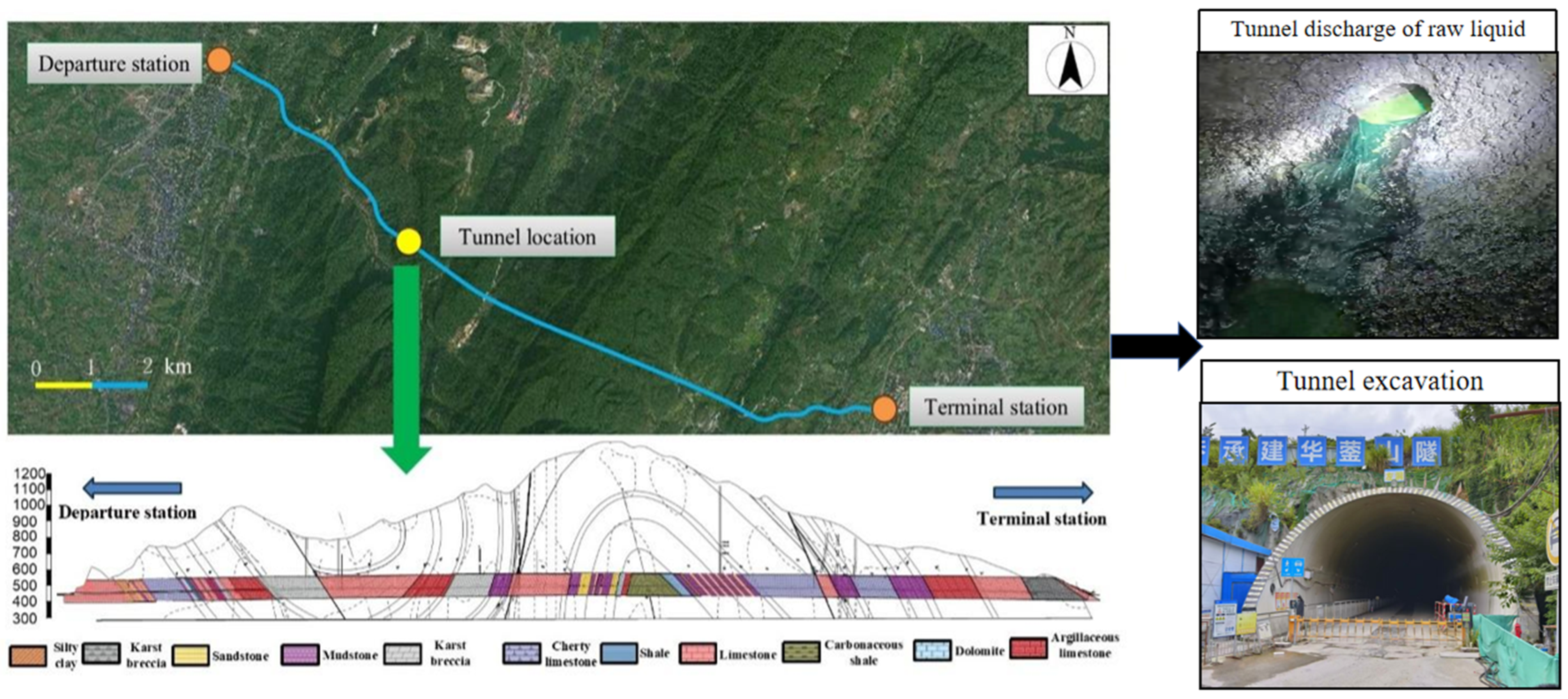
The Huaying Tunnel was selected as the engineering background for this study. It is located in the central Huaying Mountain area on the eastern margin of the Sichuan Basin, where the regional geology is controlled by the parallel ridge–valley structural belt of eastern Sichuan (Figure 1). The tunnel is designed as two separated tubes. Each tube is approximately 6.6 km long, and the maximum burial depth reaches about 900 m. These features make the project a representative deep-buried mountain tunnel with complex geological and environmental conditions. The tunnel alignment passes mainly through non-coal sedimentary formations, including the Lower Triassic Jialingjiang Formation (T1j), the Permian Qixia Formation, and the Carboniferous Huanglong Formation (C2h). Medium- to thick-bedded limestone and dolomite are the dominant lithologies, with local interlayers of argillaceous limestone, carbonaceous shale, and thin mudstone. Due to the combined effects of faulting, folding, and karstification, soluble rocks are widely developed along the tunnel route and account for nearly 80% of the total tunnel length. Karst fractures, dissolution pores, and cavities are also well developed. As a result, groundwater migration is highly uneven, and seepage channels are strongly controlled by fractured and karstified rock masses.
Field investigation and special monitoring further revealed a complex gas-bearing and corrosive environment along the tunnel. Approximately 38% of the tunnel sections were associated with methane or other toxic and hazardous gases. In addition to coal-related and structurally controlled sections, hydrogen sulfide, carbon dioxide, and oil–gas components were detected in several non-coal strata. During excavation, oil–water mixtures accompanied by natural gas and hydrogen sulfide were encountered, and relatively high gas concentrations were recorded in some sections. Groundwater testing showed that the water in the studied section had moderate corrosivity to grouting materials and concrete structures. Its organic constituents and main ionic compositions are listed in Table 1. Under these conditions, grouting is required not only for surrounding rock reinforcement and seepage control, but also for improving the durability of the support system in a multiphase corrosive environment. Therefore, this project provides a typical engineering case for investigating the performance evolution and durability mechanism of cementitious grouting materials in non-coal oil- and gas-bearing strata.

3. Experimental Procedure

3.1. Raw Materials and Preparation of Modified Grouting Specimens

P·HSR42.5 cement produced by China Huaxin Cement Co., Ltd (Huangshi, China). was selected as the main binder. Its physical and mechanical properties meet the requirements of the relevant Chinese standards [41]. The cement has a density of approximately 3.1 g/cm3, and its 28-day compressive strength is higher than 42.5 MPa. The initial setting time is not less than 45 min, while the final setting time does not exceed 600 min. The main chemical composition of the cement is given in Table 2. To improve the resistance of the grout to oil- and gas-related corrosive exposure, hydrophilic waterborne epoxy resin supplied by Qingdao Zhuonengda Construction Technology Co., Ltd (Qingdao, China). was used as a polymer modifier. The resin has a solid content of 49% and an epoxy equivalent weight of 413 g/mol. Tap water meeting the current national requirements was used for mixing [42]. All mixtures were prepared with the same reference proportion, and the water-to-cement ratio was fixed at 0.44. The epoxy dosage of 7.0% was selected with reference to the literature range of 2–20%. The 7.0% dosage is calculated by mass of cement, referring to the total amount of epoxy emulsion. This study aims to verify the improvement effect compared with the unmodified group, rather than determine the optimal content. The epoxy emulsion was directly added into the mixing water during mixing. The water from the epoxy emulsion is counted into the total water when calculating the water-to-cement ratio.
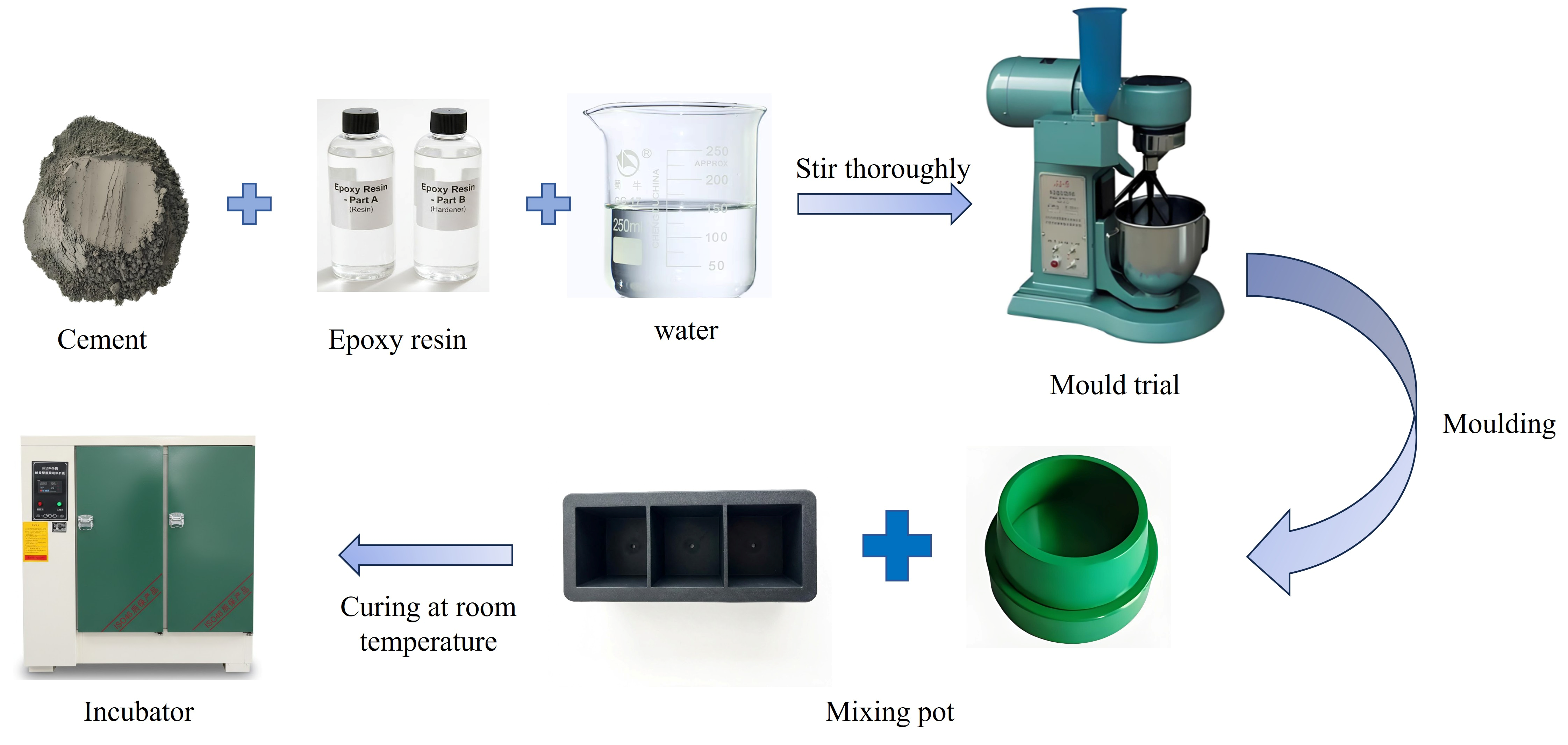
The grout was prepared according to the procedures specified in Test Methods for Water Requirement of Normal Consistency, Setting Time and Soundness of Cement (GB/T 1346-2024) [43]. During mixing, the water and admixture solution were first added to the mixing bowl, and the cement was then introduced gradually within 5–10 s to avoid splashing. The mixture was mixed at low speed for 120 s, paused for 15 s to scrape the blades and the inner wall of the bowl, and then mixed at high speed for another 120 s. Specimens were fabricated following the Standard for Test Method of Basic Properties of Building Mortar (JGJ/T 70-2009) [44]. Cubic specimens of 70.7 mm × 70.7 mm × 70.7 mm were prepared for compressive strength testing. Frustum-shaped specimens with an upper diameter of 70 mm, a lower diameter of 80 mm, and a height of 30 mm were prepared for permeability testing. After casting, the specimens were kept in molds for 24 h and then demolded. For each test condition, three specimens were used for compressive strength testing and six specimens were used for permeability testing. All demolded specimens were cured under standard conditions until the designed test ages. The preparation process is shown in Figure 2.

3.2. Experimental Program

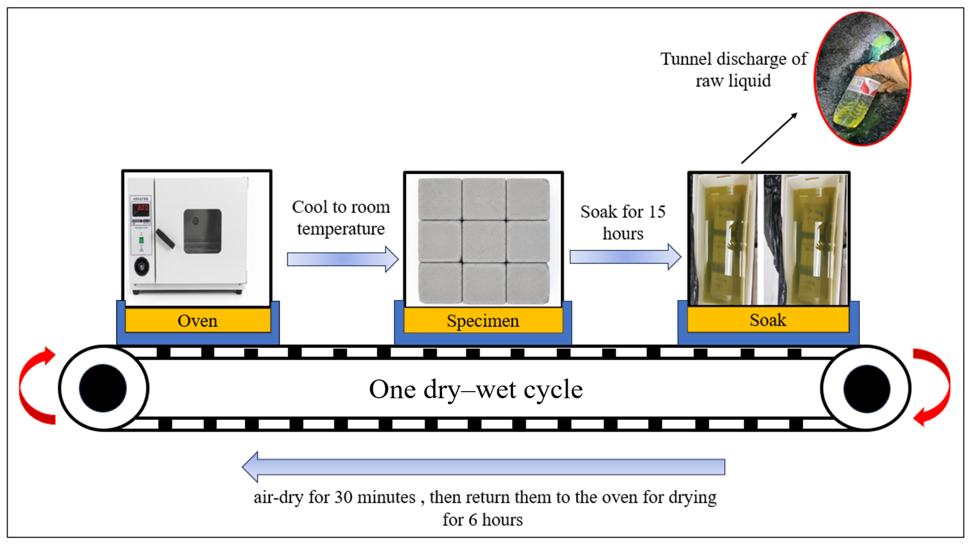
To simulate the exposure conditions of grouting materials in non-coal oil- and gas-bearing strata, the actual gushing fluid collected in March 2025 at K10 + 170 section of the right tunnel of Tunnel was used as the corrosive medium. The fluid was stored in sealed special containers and replaced every 30 days to maintain stable chemical composition during cycling. Its organic constituents and major ionic compositions are listed in Table 1. Three groups, denoted as G1, G2, and G3, were designed according to the incorporation of waterborne epoxy resin and the immersion medium used during dry–wet cycling. The detailed test configurations are given in Table 3. To accelerate the long-term deterioration of the grout under corrosive exposure, the dry–wet cycling regime was designed with reference to the sulfate attack procedure specified in the Standard for Test Methods of Long-Term Performance and Durability of Ordinary Concrete (GB/T 50082-2009) [45]. After standard curing for 26 days, the specimens were removed, surface-dried, and oven-dried at (80 ± 5) °C for 48 h. This treatment was conducted two days prior to the standard 28-day curing age. They were then cooled to room temperature under dry conditions. Subsequently, the specimens were immersed in the corresponding solutions for 15 ± 0.5 h at 25–30 °C. After immersion, they were naturally air-dried for 30 min, oven-dried for 6 h, and cooled to 25–30 °C within 2 h. This process was defined as one dry–wet cycle. The cycling procedure is shown in Figure 3. In this study, 0, 30, 60, 90, and 120 cycles were selected. The maximum number of cycles and test intervals were determined with reference to typical settings in relevant literature [46,47]. The G1 group subjected to freshwater dry–wet cycling was used as the reference group, allowing the effects of corrosive media and waterborne epoxy modification to be evaluated comparatively. After undergoing the specified number of cycles, a small block of approximately 5 mm3 was rapidly chipped from the core region of the cube (for SEM analysis) and the remainder was crushed and ground into powder (for XRD analysis). The samples were immediately immersed in anhydrous ethanol to halt hydration for 24 h, and subsequently dried in a vacuum oven at 60 °C until constant weight was achieved. Prior to observation, the SEM specimens were surface-sputtered with gold using a high-resolution sputtering system (to form a gold coating of approximately 15 nm) to enhance conductivity. It should be noted that high-temperature drying at 80 °C may affect the damage state of materials. It accelerates water evaporation and may slightly exacerbate matrix damage compared with natural air drying. However, this accelerated aging method does not alter the intrinsic corrosion mechanism of the materials and merely shortens the test period. Therefore, the derived damage evolution law can still reflect the long-term degradation trend of grouting materials in practical engineering.
To characterize the degradation of grouting materials under oil- and gas-bearing corrosive exposure, mechanical, permeability, nondestructive, and microstructural tests were conducted after different numbers of dry–wet cycles. The mechanical properties were evaluated by uniaxial compressive strength and elastic modulus tests on cubic specimens. The specimens were loaded to failure at a constant loading rate, and the elastic modulus was calculated from the linear portion of the stress–strain curve to quantify stiffness degradation. The impermeability performance was evaluated using impermeability pressure as the main indicator. During the test, water pressure was increased stepwise, and the impermeability pressure was defined as the maximum pressure sustained without seepage by at least four of the six specimens in each group. A permeability retention ratio was further introduced to quantify the loss of impermeability caused by cyclic corrosion. The impermeability retention ratio is defined as the ratio of the impermeability pressure after N cycles to the initial pressure, following the principles for evaluating long-term performance degradation as per GB/T 50082-2009 [45]. Ultrasonic pulse velocity measurements were performed at different cycling stages to monitor internal damage nondestructively, with changes in longitudinal wave velocity used to reflect pore coarsening and microcrack development. Representative specimens were also examined by scanning electron microscopy and X-ray diffraction. SEM was used to observe pore structure, microcracks, and corrosion products, while XRD was used to identify mineral phase evolution, especially the formation of expansive products such as ettringite and gypsum. The damage evolution under coupled corrosion and dry–wet cycling was evaluated using macroscopic, nondestructive, and microstructural analyses.

3.3. Test Apparatus

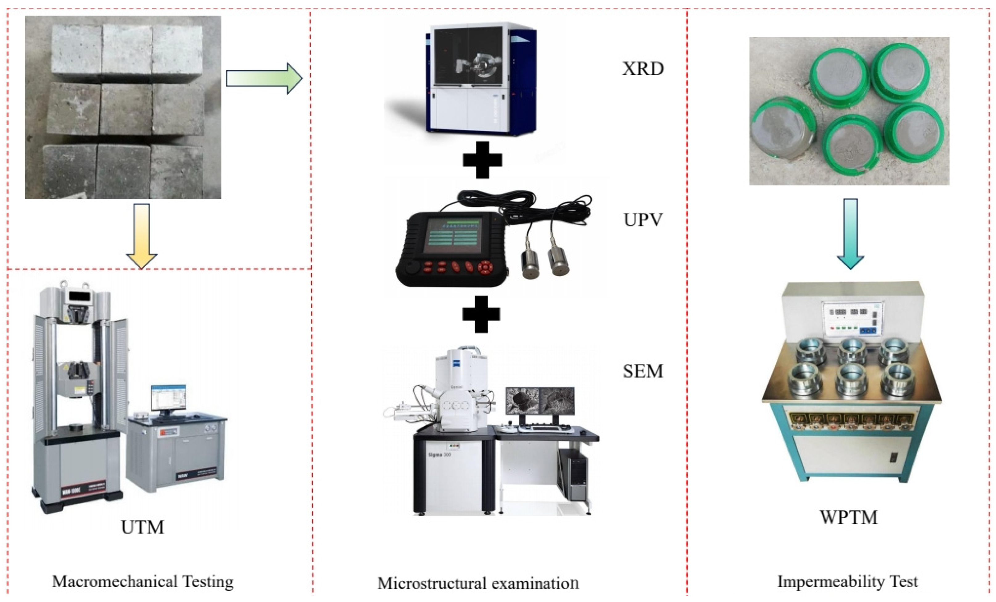
The main instruments used for mechanical, permeability, nondestructive, and microstructural tests are presented in Figure 4. The compressive strength and elastic modulus of the grouting materials were measured using a WAW-1000 electro-hydraulic servo universal testing machine. The equipment has a maximum axial loading capacity of 1000 kN and can record load and displacement data during loading. The elastic modulus was calculated from the complete stress–strain curves obtained from the recorded load and displacement data. Impermeability tests were carried out using an SS-15 mortar permeability tester, which allowed stepwise hydraulic pressure loading during the test. The microstructure and phase composition of the specimens were examined using a JSM-7800F scanning electron microscope and a D8 Advance X-ray diffractometer, respectively. SEM was used to observe pore structure, microcracks, and corrosion products, while XRD was used to identify changes in hydration products and corrosion-related mineral phases before and after exposure. In addition, a ZT108 ultrasonic pulse velocity tester was used for nondestructive evaluation of internal defects. The instrument has a transit time measurement range of 0–640,000 μs and an accuracy of ±0.05 μs, which meets the requirements for tracking wave velocity changes caused by internal damage development.

4. Experimental Results Analysis

4.1. Evolution of Mechanical Properties

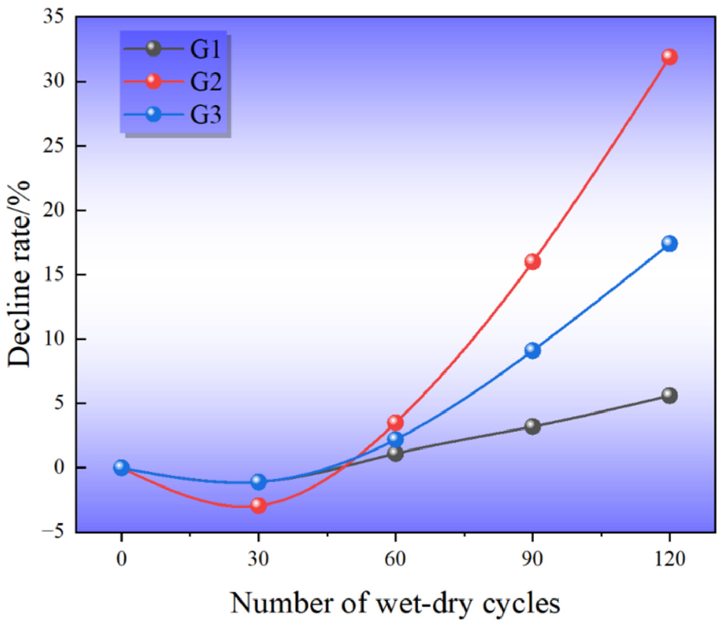
The compressive strength and elastic modulus of the grouting materials under different exposure conditions are listed in Table 4. Their variations with dry–wet cycles are shown in Figure 5 and Figure 6. In general, the mechanical response of the specimens showed two stages: a slight increase or limited change at the early exposure stage, followed by gradual deterioration as the number of cycles increased. This trend was more evident in the corrosion group than in the reference and modified groups. As shown in Figure 5, the compressive strength of G2 increased slightly from 37.4 MPa to 38.5 MPa after 30 cycles. This increase may be related to the filling effect of early reaction products, which temporarily densified the pore structure. With further cycling, however, the degradation effect became dominant. The compressive strength of G2 decreased to 31.4 MPa after 90 cycles and further dropped to 26.2 MPa after 120 cycles, corresponding to a total reduction of 31.9%. In comparison, G1 retained a strength of 35.3 MPa after 120 cycles, with a loss of only 5.6%. The waterborne-epoxy-modified group G3 maintained a higher strength of 30.0 MPa at 120 cycles, and its total loss was limited to 17.4%. This indicates that the incorporation of waterborne epoxy resin improved the resistance of the grout to corrosion-induced strength degradation.
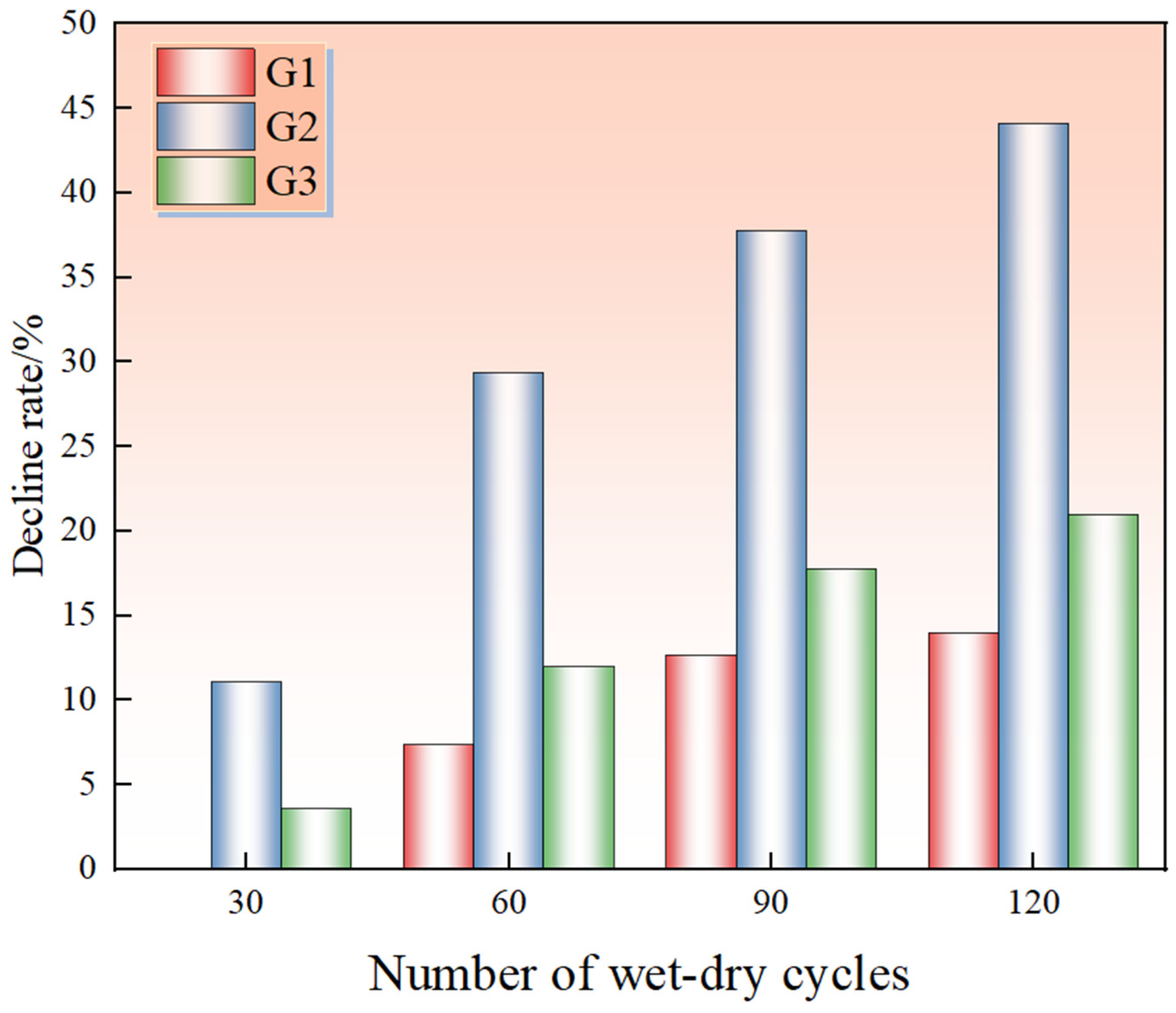
The elastic modulus showed a similar but more sensitive response to cyclic corrosion, as shown in Figure 6. During the first 30 cycles, the elastic modulus of G2 and G3 decreased slightly, whereas that of G1 remained almost unchanged. As exposure continued, the stiffness loss of G2 became increasingly pronounced. After 120 cycles, its elastic modulus decreased to 21.2 GPa, with a cumulative reduction of 44.1%. Although G3 also showed a decreasing trend, the degradation rate was much lower. Its elastic modulus remained at 28.9 GPa after 120 cycles, corresponding to a loss of 21.0%. Compared with compressive strength, elastic modulus was more sensitive to internal damage, indicating that stiffness degradation can reflect microcrack development and matrix loosening at an earlier stage.
The above results suggest that the coupled action of corrosive ions, organic components, and dry–wet cycling caused a transition from early-stage densification to damage-dominated degradation. At the early stage, limited reaction products may fill pores and slightly improve strength. At later stages, aggressive media gradually accumulated and migrated within the matrix, promoting pore coarsening, microcrack initiation, and crack coalescence. These changes reduced both the load-bearing capacity and stiffness of the grout. The waterborne epoxy resin helped slow this process by improving matrix integrity and reducing connected transport pathways. As a result, the modified grout exhibited better mechanical stability under long-term corrosive exposure.

4.2. Evolution of Impermeability Performance

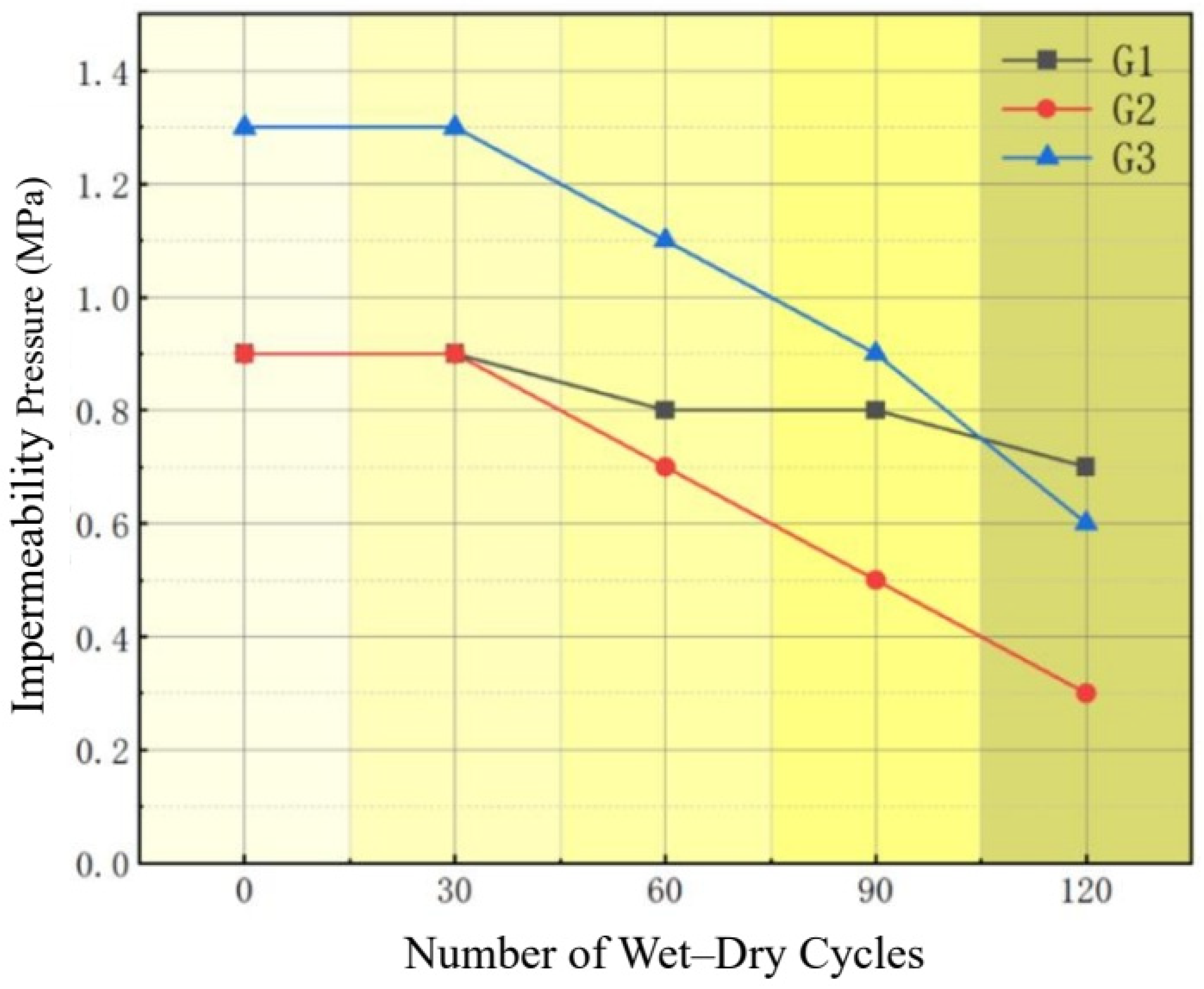
As shown in Figure 7, the impermeability performance of the grouting materials changed differently under the three exposure conditions as the number of dry–wet cycles increased. The reference group G1 showed only slight deterioration. Its impermeability pressure decreased from 0.9 MPa to 0.7 MPa after 120 cycles, corresponding to a retention ratio of 77.8%. By contrast, the corrosion group G2 exhibited a much faster loss of impermeability. Its impermeability pressure decreased to 0.5 MPa after 90 cycles and further dropped to 0.3 MPa after 120 cycles. The final retention ratio was only 33.3%, indicating that the corrosive medium significantly weakened the seepage resistance of the grout. The modified group G3 showed better resistance to permeability degradation. Its initial impermeability pressure reached 1.3 MPa, higher than those of G1 and G2. After 120 cycles in tunnel effluent, G3 still retained an impermeability pressure of 0.6 MPa, about twice that of G2 at the same stage, with a retention ratio of 46.2%.
The above results indicate that the corrosive components in the tunnel effluent accelerated the deterioration of the internal pore structure of the grout. With repeated dry–wet cycling, aggressive media may accumulate and migrate within the matrix, increasing pore connectivity and forming preferential seepage paths. This process led to a rapid decrease in impermeability pressure in G2. The addition of waterborne epoxy resin effectively improved the initial impermeability of the grout and reduced the rate of impermeability loss during cyclic exposure. This improvement may be attributed to the filling and film-forming effects of the epoxy phase epoxy fills micropores to shrink capillary channels and forms hydrophobic continuous films on pore walls, which helped reduce connected pores and restrain microcrack development. Therefore, the modified grout showed better resistance to seepage deterioration under corrosive dry–wet cycling.

4.3. Microstructural Analysis

4.3.1. Microstructural Morphology

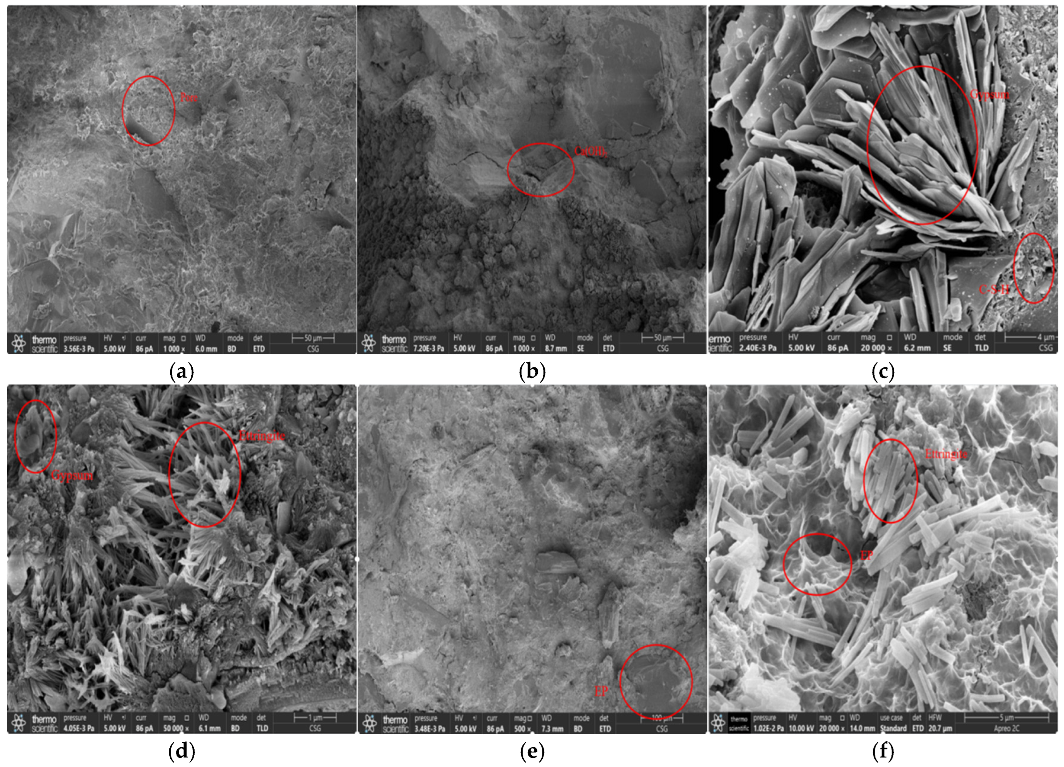
SEM observations were performed to further reveal the microstructural evolution of the grouting materials after dry–wet cycling in tunnel effluent. Representative specimens from G1 and G2 were selected after 30, 90, and 120 cycles, while G3 was mainly examined after 120 cycles to evaluate the long-term effect of waterborne epoxy modification. As shown in Figure 8a, the reference group G1 retained a relatively dense and intact matrix after clean-water cycling. Only a small number of isolated micropores were observed. Hydration products remained clearly distinguishable, and no obvious connected cracks or corrosion product accumulation appeared. This suggests that dry–wet cycling in clean water caused limited damage to the microstructure of the grout.
In contrast, G2 showed a clear progressive damage pattern under tunnel effluent exposure. After 30 cycles (Figure 8b), the matrix was still relatively compact, but slight Ca(OH)2 precipitation appeared along the pore edges. After 90 cycles (Figure 8c), plate-like gypsum crystals began to develop. At the same time, the C–S–H gel became looser, and microcracks started to extend along pore boundaries. After 120 cycles (Figure 8d), abundant needle-like and rod-like corrosion products, mainly ettringite and gypsum, filled the pores and cracks. These products gradually connected isolated defects and formed a crack–pore network. The crystallization and expansion of corrosion products generated internal pressure, which promoted crack propagation and provided a microstructural explanation for the rapid loss of impermeability and mechanical properties.
The modified group G3 exhibited a different microstructural response under the same exposure condition (Figure 8e,f). A continuous or semi-continuous polymer film was observed in the matrix after waterborne epoxy curing. This film covered part of the hydration products and filled some pores, making the structure more compact. Even after 120 cycles, the corrosion products in G3 remained relatively fine and dispersed, and no extensive connected crack network was observed. This indicates that waterborne epoxy resin helped reduce the penetration of aggressive media and limited crack connectivity. As a result, the development of microstructural damage was effectively slowed.

4.3.2. Phase Evolution Analysis

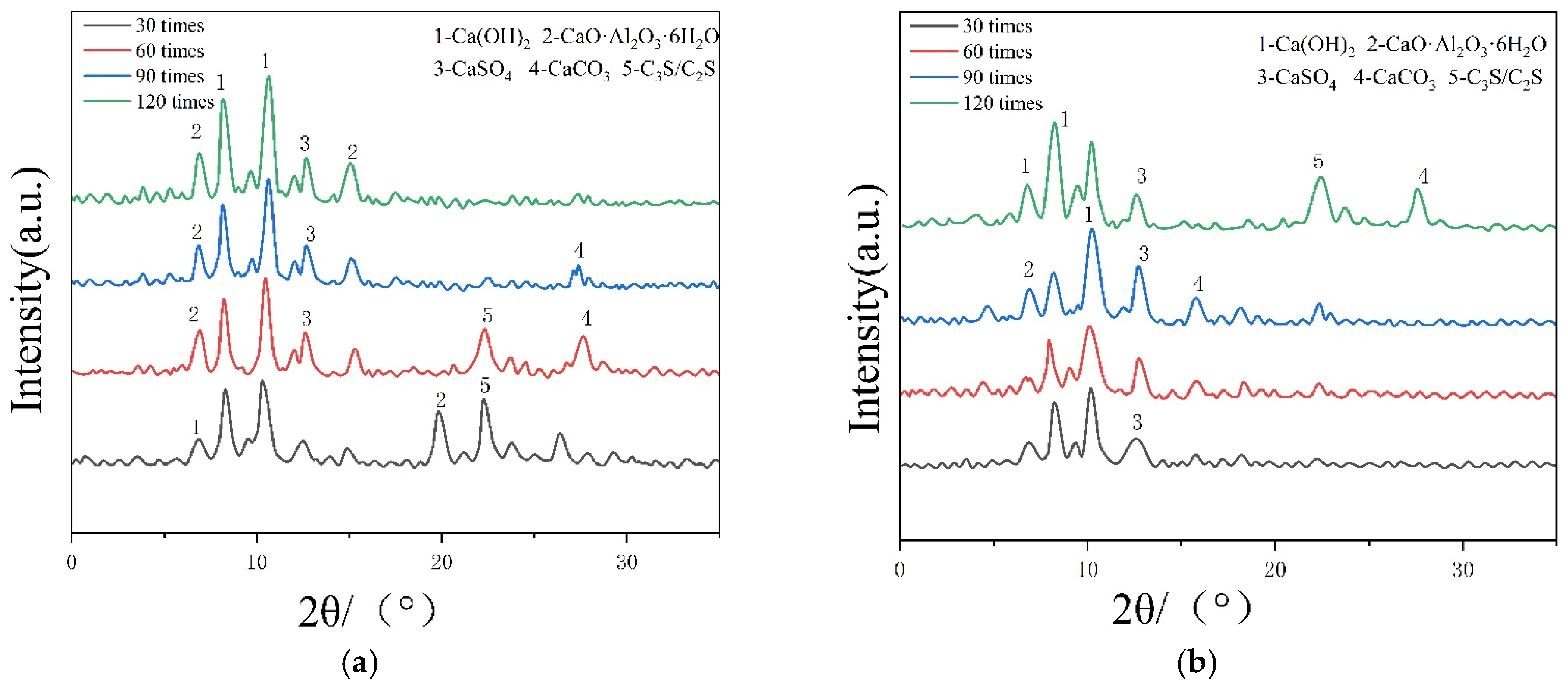
XRD analysis was conducted to further identify the phase changes responsible for the microstructural differences observed by SEM. As shown in Figure 9, the main diffraction peaks were associated with hydration products such as CaO·Al2O3·6H2O, Ca(OH)2, and CaCO3, together with residual C2S/C3S and corrosion-related phases such as CaSO4. After 30 dry–wet cycles, Ca(OH)2 and silicate-related phases remained dominant, while the CaSO4 peaks were still weak. This indicates that the corrosion reaction was at an early stage. As the number of cycles increased to 60, the peak intensities of Ca(OH)2 and silicate phases decreased, whereas the peaks of CaSO4 and CaCO3 became stronger, suggesting that sulfate-related reactions had gradually intensified. After 90 cycles, the Ca(OH)2 peaks decreased more clearly, and the CaSO4 peaks increased further. Meanwhile, the CaCO3 peaks started to weaken, indicating that carbonate phases were also involved in the corrosion process. At 120 cycles, the diffraction peaks of Ca(OH)2 and CaCO3 were greatly reduced or nearly absent, while the CaSO4 peaks became more pronounced. These changes indicate that the material had entered an advanced corrosion stage. Combined with the SEM results, the XRD evidence suggests that the continuous consumption of CaO/Ca(OH)2 and silicate phases promoted the formation of gypsum and other sulfate corrosion products, which contributed to pore filling, crystallization pressure, and crack propagation. The multifaceted role of carbonation in this complex oil and gas tunnel environment: (1) The dissolution of carbon dioxide gas triggers early natural carbonation reactions, consuming part of the Ca(OH)2 and generating CaCO3; in the early stages, this also exerts a slight pore micro-consolidation effect; (2) However, in the later stages, high-density CaCO3 undergoes highly destructive Thaumasite-type sulphate erosion reactions in the high-concentration SO42− environment underground, causing the C-S-H gel to completely lose its gel matrix structure and transform into a paste-like substance devoid of strength. This explains the underlying microscopic chemical mechanism behind the powdery disintegration of the matrix after 120 cycles.
Compared with the unmodified specimens, the epoxy-modified samples showed slower changes in the main corrosion-related phases under the same exposure condition. The reduction in Ca(OH)2 peak intensity was less pronounced, and the increase in CaSO4 peak intensity was also weaker. This indicates that waterborne epoxy resin delayed the reaction between aggressive media and the cementitious matrix. The polymer phase reduced direct contact between corrosive solutions and hydration products by limiting transport pathways within the matrix. As a result, the consumption of original hydration products was slowed, and the formation of expansive corrosion products was restrained. This phase evolution is consistent with the SEM observations and provides further evidence for the improved durability of the modified grout. After complete cross-linking and curing, the long-chain polymer network of water-based epoxy resin (WER) exhibits a highly disordered long-range structure, i.e., a typical amorphous polymer. Consequently, unlike minerals such as alunite or gypsum, it does not exhibit sharp Bragg diffraction peaks with specific crystal lath indices in X-ray diffraction (XRD) spectra; instead, it contributes only an extremely gentle, barely perceptible broad peak (diffuse bun-shaped peak) between 2θ = 15–25°. This is precisely the fundamental physical reason why XRD cannot directly perform quantitative crystal identification on cured epoxy resins.
When the refined quantitative data from the full XRD spectrum revealed that the mass fraction of gypsum surged from 2.1% to 18.4% during the 60–120th cycles, we immediately highlighted in the corresponding Figure 8d (SEM image) the typical “flaky/plate-like crystalline structures” (i.e., gypsum morphology) in the corresponding Figure 8d (SEM image); Similarly, the near-complete disappearance of the Ca(OH)2 peak in the XRD perfectly corresponds, in the SEM, to the ‘reticulated, friable, and eroded’ void morphology exhibited by the C-S-H cementitious matrix due to severe decalcification.

4.3.3. UPV Assessment of Internal Damage

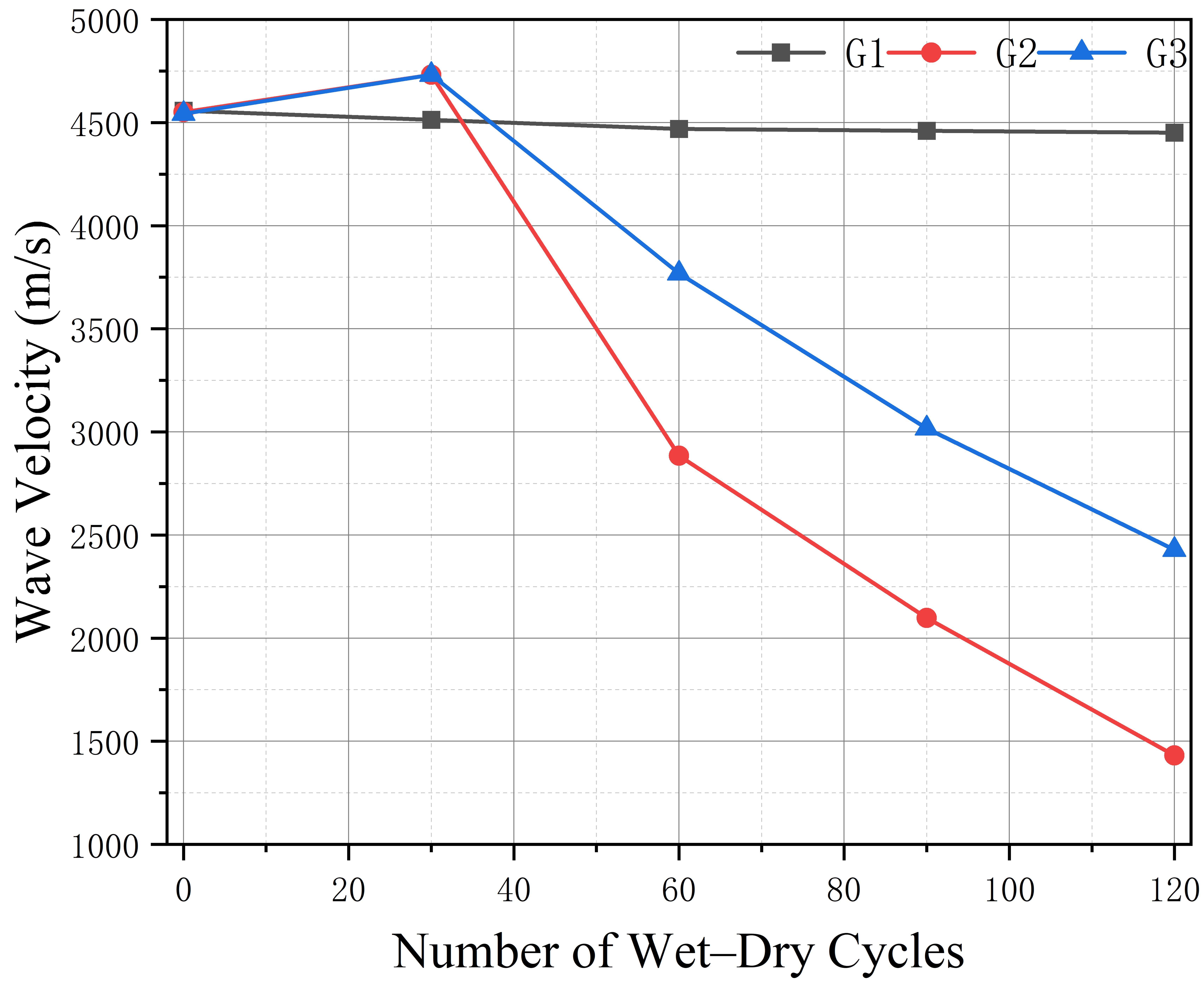
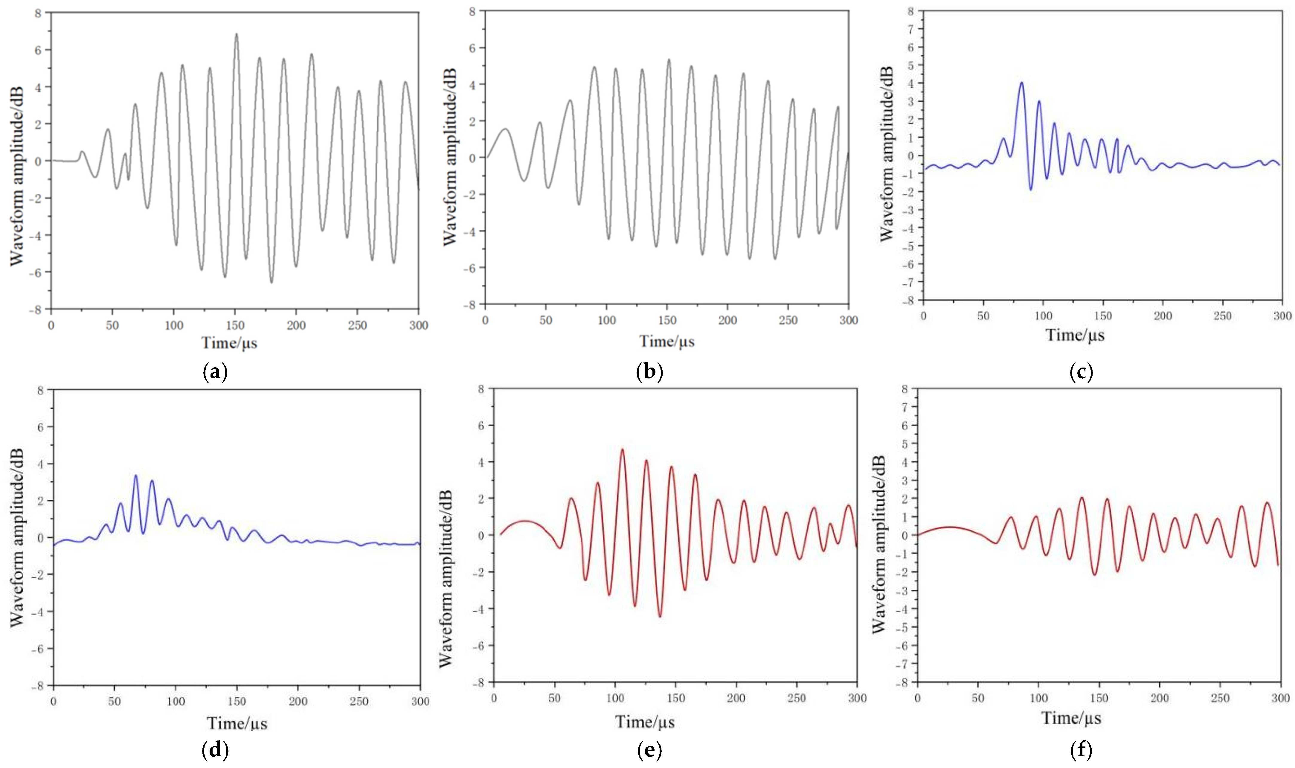
To evaluate the development of internal damage during dry–wet cycling and the mitigation effect of waterborne epoxy, UPV tests were conducted on G1, G2, and G3 specimens after 30 and 120 cycles. All UPV measurements were conducted after surface drying and under controlled room temperature conditions to minimize the influence of moisture variation on ultrasonic propagation results. The corresponding velocity and waveform results are shown in Figure 10 and Figure 11. As shown in Figure 10, the longitudinal wave velocity of G1 decreased only slightly under clean-water cycling, indicating that its internal structure remained relatively stable. In contrast, G2 and G3 exposed to tunnel effluent showed a similar trend of a slight early increase followed by a clear decrease. The early increase before 30 cycles may be attributed to temporary pore filling by corrosion products. With further cycling, microcracks initiated and gradually connected, leading to a rapid decrease in wave velocity. After 120 cycles, the velocity reduction of G2 reached approximately 3000 m/s, whereas that of G3 was limited to about 2000 m/s. This indicates that aggressive media and cyclic exposure promoted internal defect accumulation, while waterborne epoxy slowed the damage process by improving matrix compactness and restraining crack propagation. This massive reduction of 67% is indeed extremely rare in ordinary, intact concrete structures; however, for the cement paste grout (C25 mortar/pure paste) without coarse aggregate used in this experiment, after undergoing 120 cycles of extremely severe dry–wet erosion by acidic oil and gas, macroscopic through-cracks allowing fluid penetration had formed within the specimen and the matrix had become severely ‘crumbly’ (the waveform approaches linear disintegration, see Figure 11d). Due to the extremely high acoustic scattering and diffraction impedance of sound waves at the air/crude oil-filled cracks, the sound transit time is drastically prolonged; consequently, the precipitous drop in wave velocity is a genuine, objective phenomenon that fully conforms to the laws of physics.
The ultrasonic waveforms further reflected the evolution of internal defects under different exposure conditions (Figure 11). Under clean-water cycling, the waveforms of G1 remained generally stable after both 30 and 120 cycles (Figure 11a,b), with only minor changes in wave velocity and amplitude. This suggests that dry–wet cycling alone had a limited effect on the structural continuity of the grout. In the corrosion group G2, the waveform changed markedly after exposure to tunnel effluent. After 30 cycles (Figure 11c), the wave velocity decreased by about 2.3%, and the waveform showed steep fluctuations with a maximum amplitude close to 6 dB, indicating localized internal damage. After 120 cycles (Figure 11d), the increase in pores and cracks further disturbed the ultrasonic propagation path. Signal attenuation became more obvious, and the waveform gradually became smoother. The overall attenuation rate increased by approximately 67–83% compared with the 30-cycle stage, suggesting that microcracks evolved from isolated defects into a more connected damage network. By contrast, G3 showed a different waveform response. After 30 cycles (Figure 11e), large peak-to-valley fluctuations of about 12 dB were still observed, indicating that the internal structure remained relatively compact. After 120 cycles (Figure 11f), although attenuation of about 2–4 dB occurred, the waveform deterioration was much weaker than that of G2. This confirms that waterborne epoxy helped restrain crack growth and reduce defect connectivity.
A comparison among the three groups at the same cycling stage further supports this interpretation. After 30 cycles (Figure 11a,c,e), G1 retained a sharp waveform, while G2 showed noticeable waveform smoothing due to corrosion-induced pore and crack formation. The waveform of G3 was less smoothed than that of G2, indicating a protective effect of the modified matrix. After 120 cycles (Figure 11b,d,f), the waveform of G2 approached a nearly linear pattern, reflecting severe loss of structural continuity. In contrast, G3 still maintained clear fluctuations, suggesting lower microcrack connectivity. Overall, UPV and waveform results show that waterborne epoxy resin improved matrix compactness, delayed crack connection, and enhanced resistance to corrosion-induced internal damage.

5. Discussion

5.1. Mechanical Performance Prediction Model

To comprehensively evaluate the strength degradation of grouting materials subjected to wet–dry cycles in tunnel seepage solution, a nonlinear regression approach was adopted to establish a calculation model for the critical degradation threshold cycle number, The critical degradation threshold cycle number, Based on the experimental observations, the strength and modulus degradation under all three conditions exhibited a two-stage characteristic: an initial stable or slightly rising period, followed by an accelerated declining phase. Therefore, an exponential decay function, which has been widely used in concrete durability studies to describe such deterioration patterns, was employed in this study. The critical degradation threshold cycle number, n c , is defined as the specific number of wet–dry cycles at which the compressive strength begins a sustained decrease after any initial period of stability or temporary increase. This threshold marks the onset of the damage-dominated degradation phase and is determined by fitting Equation (1) to the experimental data, as expressed in Equation (1):
n c = A e b n
where n denotes the number of wet–dry cycles, and n c represents the critical degradation threshold cycle number, beyond which the compressive strength begins to exhibit a sustained decreasing trend. A and b are fitting parameters related to the corrosive medium and the composition of the grouting material. Where A represents the theoretical maximum critical threshold (at n = 0) and is related to the material’s innate resistance; b is a decay constant representing how rapidly the threshold decreases with each cycle, reflecting the material’s sensitivity to cyclic damage. The parameter k in the following model reflects the deterioration rate once the material enters the accelerated degradation stage, with higher k values indicating faster performance loss under aggressive corrosion. Considering that strength deterioration under coupled wet–dry cycling exhibits pronounced post-peak attenuation and long-term degradation behavior, a prediction model for compressive strength evolution after the critical degradation threshold was further established, as given in Equation (2):
f c n = f c 0 n c e k ( n n c )  
where k represents the dry–wet cycling degradation coefficient, which is positively correlated with the aggressiveness of the corrosive medium and the intrinsic corrosion resistance of the material. A higher k indicates a faster rate of strength loss once the critical threshold is exceeded, representing the material’s vulnerability to progressive damage. f c 0 n c denotes the compressive strength at the critical degradation threshold cycle (MPa), All model parameters were calibrated based on the experimental data obtained in this study, and the models are strictly applicable within the range of 0 to 120 wet–dry cycles. n is the number of dry–wet cycles, and f c n is the compressive strength after n cycles (MPa). Model fidelity was evaluated using stratified five-fold cross-validation under different corrosion conditions. Uncertainty was quantified through 95% prediction intervals (PI) derived from the residual variance, accompanied by residual diagnostics.
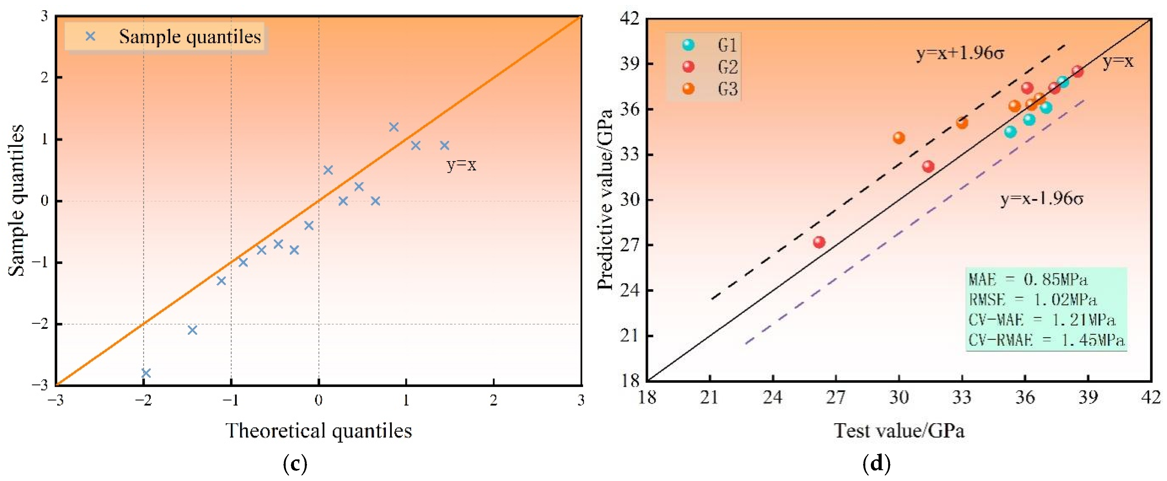
The results show that the deviation between model predictions and experimental measurements ranged from 0.3% to 7.8%, with the overall error below 8%. After refinement, the in-sample errors were MAE = 0.85 MPa and RMSE = 1.02 MPa, while cross-validation yielded CV-MAE = 1.21 MPa and CV-RMSE = 1.45 MPa. Within the calibration range (0–120 dry–wet cycles under three corrosion scenarios), the 95% prediction interval achieved 100% empirical coverage. Residual analysis showed no systematic bias, and the Q–Q plot was approximately normal. These results confirm that the critical degradation threshold model and post-peak strength attenuation model can reliably describe compressive strength evolution under different corrosion environments (see Figure 12).
The experimental results indicate that under dry–wet cycling with tunnel inflow liquid as the exposure medium, the elastic modulus of the grouting material exhibits a pronounced degradation trend with increasing cycle number. The evolution process is jointly governed by the type of corrosive medium and the material modification strategy. In particular, specimens subjected to crude-oil immersion show an evident reduction in mechanical performance even at the early exposure stage, whereas the incorporation of waterborne epoxy resin demonstrates a noticeable retardation effect on stiffness deterioration. To quantitatively characterize the degradation behaviour of elastic modulus under different corrosion scenarios, it is necessary to establish a nonlinear predictive model incorporating a critical degradation threshold.
According to the experimental observations, the elastic modulus under water exposure (G1) remains relatively stable during the initial dry–wet cycles. In contrast, under oil-related corrosive conditions (G2 and G3), the material enters a rapid deterioration stage at an early phase. This behaviour suggests the existence of a critical dry–wet cycle threshold, before which the mechanical properties remain comparatively stable, and beyond which the elastic modulus undergoes continuous degradation.
Based on these characteristics, an exponential function is adopted to fit the critical degradation threshold cycle number, which can be expressed as follows:
N c = A e x p b C
where N c denotes the critical degradation threshold in terms of dry–wet cycle number; C represents the corrosion condition parameter, which characterizes the combined effect of corrosive medium and material modification; and A and c are regression fitting coefficients. By substituting the experimental data from each exposure condition into Equation (3) and performing nonlinear regression analysis, the critical degradation thresholds of the grouting material under different corrosion environments can be determined. The results indicate that crude-oil-related corrosion significantly reduces the threshold value, whereas waterborne epoxy modification effectively increases the threshold, thereby delaying the transition into the rapid deterioration stage.
Considering that the degradation process under oil–gas corrosive environments exhibits pronounced stage-dependent characteristics, it is necessary to further establish a predictive model describing the evolution of elastic modulus with dry–wet cycles beyond the critical degradation threshold. Based on the experimental observations, the post-threshold decay of elastic modulus can be reasonably described using an exponential attenuation function:
E N = E 0 C e x p k C N N c N N c
where E ( N ) represents the elastic modulus after N dry–wet cycles; E 0 ( C ) denotes the elastic modulus corresponding to the critical degradation threshold N c ; k ( C ) is the corrosion degradation coefficient reflecting the influence of different corrosive media on the deterioration rate; and N is the number of dry–wet cycles.
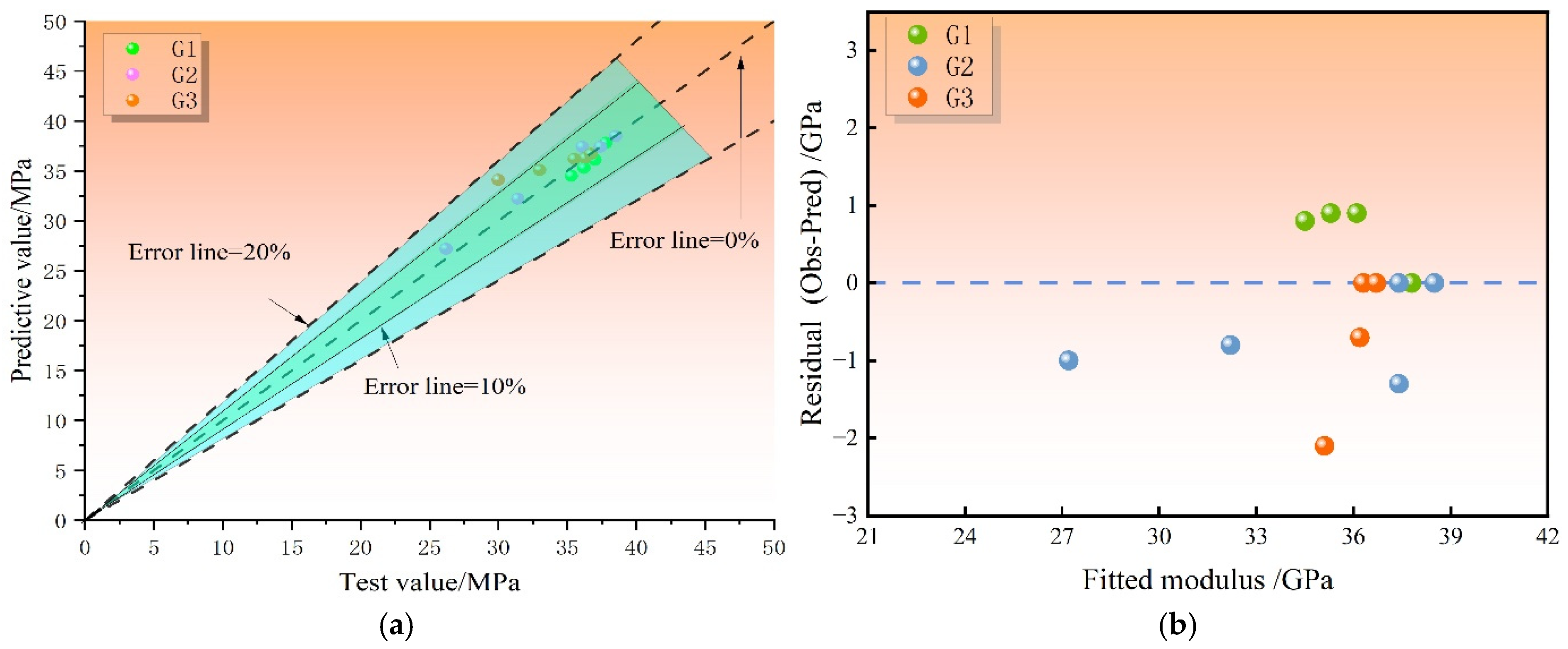
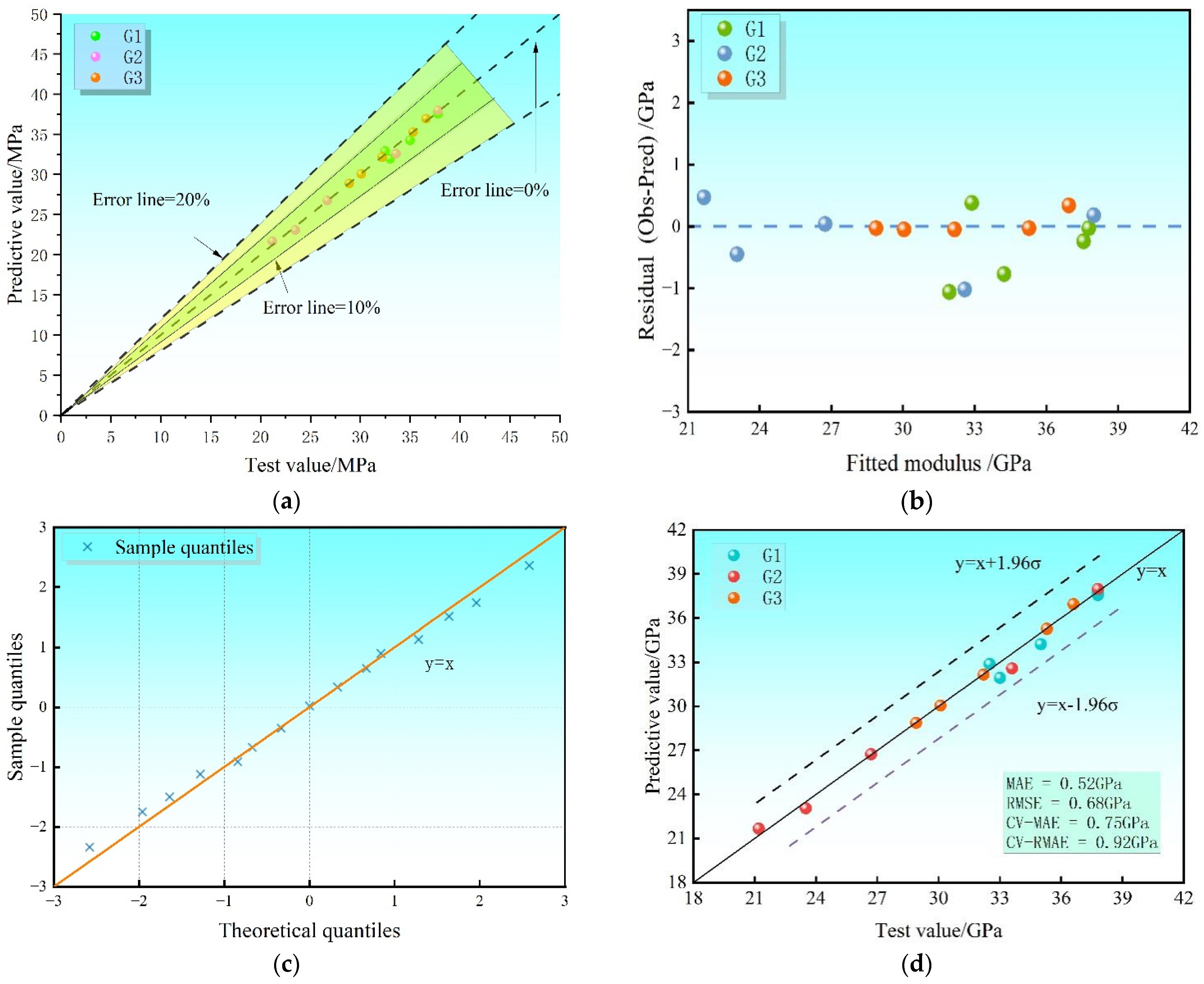
The fidelity of the proposed model was evaluated using stratified five-fold cross-validation. Model uncertainty was quantified through the 95% prediction interval (PI) derived from the residual variance and further verified through residual diagnostics. The results indicate that, under different corrosion conditions, the relative error between model predictions and experimental measurements ranges from 0.3% to 7.8%, with an overall error below 8%, satisfying the accuracy requirements for engineering prediction. For the calibrated model, the in-sample mean absolute error (MAE) and root mean square error (RMSE) are 0.52 GPa and 0.68 GPa, respectively. Under cross-validation, the average absolute error (CV-MAE) is 0.75 GPa and the root mean square error (CV-RMSE) is 0.92 GPa, demonstrating good model stability and relatively low prediction uncertainty. The 95% prediction interval achieves 100% empirical coverage within the calibration domain (0–120 dry–wet cycles) and is reported together with all prediction results. Residual analysis shows no systematic bias related to cycle number or corrosion condition, and the residual distribution approximates normality. The quantile–quantile (Q–Q) plot exhibits data points distributed closely along the diagonal line, further confirming the adequacy of the adopted error model for engineering design applications (as shown in Figure 13).

5.2. Permeability Resistance Classification

The permeability resistance of the grouting materials was classified in strict accordance with the Standard for Test Methods of Basic Properties of Building Mortar (JGJ/T70-2009). This standard specifies specimen preparation, testing apparatus, pressure application procedures, and the fundamental criteria for permeability grading, where the impermeability pressure is adopted as the primary evaluation index. Based on the engineering requirements of the Huaying Mountain tunnel, where grouting materials are subjected to long-term oil–gas corrosion, cyclic wetting–drying exposure, and high in situ stress conditions, a four-level grading method considering both impermeability pressure and retention stability was established. The detailed classification criteria are listed in Table 5.
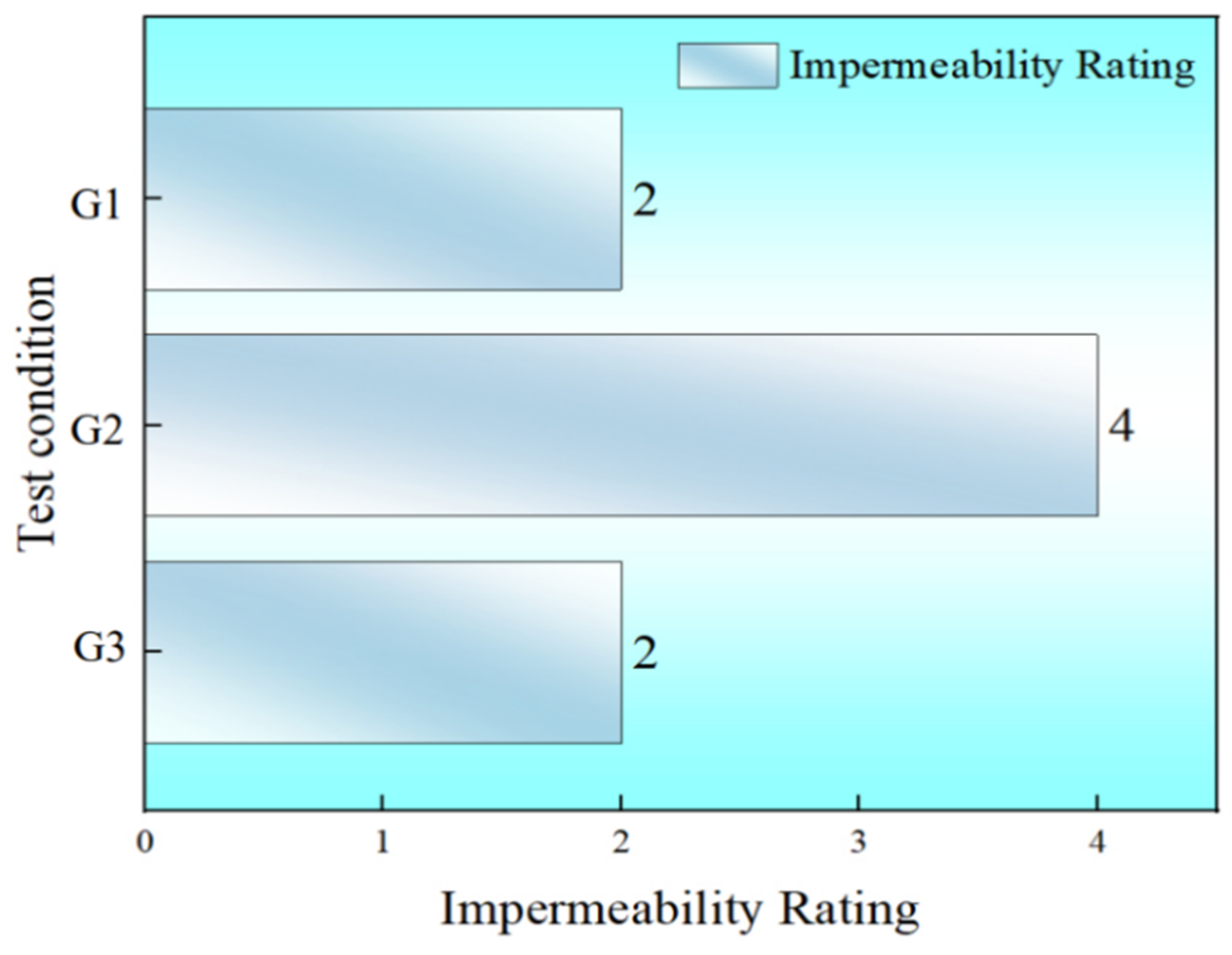
The experimental results indicate that the reference group G1 retained an impermeability pressure of 0.7 MPa after 120 dry–wet cycles in clean water, with a retention ratio of 77.8%, satisfying the Level II criteria (retention ≥ 60% and pressure ≥ 0.6 MPa) [18,46]. Its initial impermeability pressure of 0.9 MPa also met the auxiliary Level II requirement (0.9–1.2 MPa) and was therefore classified as Level II. The corrosion group G2 initially exhibited an impermeability pressure of 0.9 MPa, corresponding to Level II performance. After 30 cycles, the pressure remained at 0.9 MPa with a retention ratio of 99.9%, still meeting Level II. However, after 90 cycles the pressure sharply decreased to 0.5 MPa (retention 55.6%), falling below the Level II threshold but remaining above the Level III criterion (0.3 MPa). After 120 cycles, the pressure further declined to 0.3 MPa with a retention ratio of 33.3%, which is below the Level III retention requirement (≥40%) and at the lower boundary of Level III pressure, and was therefore classified as Level IV [10,11]. In contrast, the modified group G3 maintained an impermeability pressure of 0.6 MPa after 120 cycles in the tunnel effluent solution, with a retention ratio of 46.2%, satisfying the Level II core criteria (retention ≥ 45% and pressure ≥ 0.5 MPa). Its initial pressure of 1.3 MPa also fulfilled the auxiliary Level II requirement (≥0.9 MPa), leading to an overall Level II classification. To avoid premature overgeneralization prior to extensive field-scale validation, this proposed evaluation framework is conceptually presented as a preliminary proposal, serving as a targeted reference for similar underground infrastructures while establishing a baseline for future multi-batch calibration. The permeability resistance grades under different conditions are summarized in Figure 14.

5.3. Service Life Prediction and Durability Implications

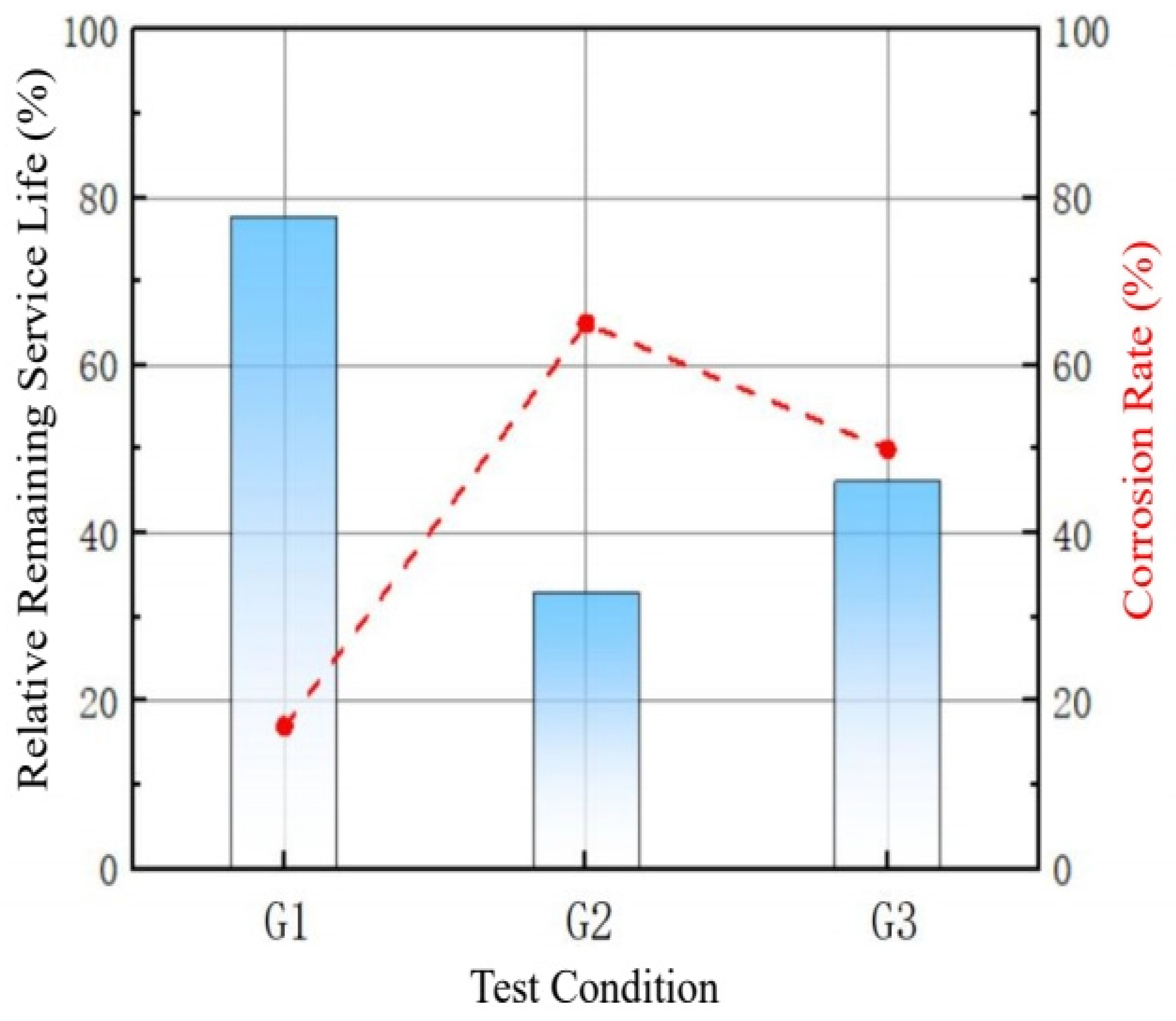
To evaluate the service life of grouting materials under oil–gas corrosive environments, a multi-performance failure criterion was established based on the long-term durability testing framework specified in GB/T50082-2009 and JTJ/T F30-2004. Taking the properties of specimens under standard curing (0 dry–wet cycles) as the reference, material failure was defined as a 50% reduction in any key performance indicator, a conservative empirical threshold recommended by relevant engineering specifications; conversion between laboratory cycles and practical service life is derived from existing empirical statistics, and probabilistic reliability analysis is not performed due to experimental constraints. By coupling this criterion with the developed strength degradation model, the theoretical service life of grouting materials under different exposure conditions was estimated (Figure 15).
It should be noted that, in practical tunnel environments, the degradation and failure of grouting materials are governed not only by intrinsic material deterioration but also by factors such as in situ stress redistribution, interaction within the support system, and dynamic variations in oil–gas seepage pressure. Therefore, the predicted service life in this study reflects the material-level durability under coupled corrosion and dry–wet cycling, providing a reference for maintenance planning rather than representing the actual structural failure time. Based on the proposed criterion and the observed performance evolution, the G2 condition exhibited an accelerated degradation trend with increasing cycle number. After 120 dry–wet cycles, the compressive strength loss reached approximately 30%, while the permeability resistance decreased by about 68%, exceeding the defined failure threshold and indicating entry into a rapid deterioration stage. In contrast, the G1 specimens maintained relatively stable performance, with strength and permeability reductions of only 5.6% and 22.2%, respectively, remaining within a safe service range. The epoxy-modified G3 specimens showed a markedly delayed degradation process, with all performance losses controlled within 30% after 120 cycles, indicating a substantially reduced failure risk. Compared with the unmodified system, the incorporation of waterborne epoxy effectively prolonged the predicted service life and improved durability stability under multiphase corrosive conditions, highlighting its potential for enhancing long-term reliability in oil–gas-bearing tunnel environments.

5.4. Damage and Inhibition Mechanisms

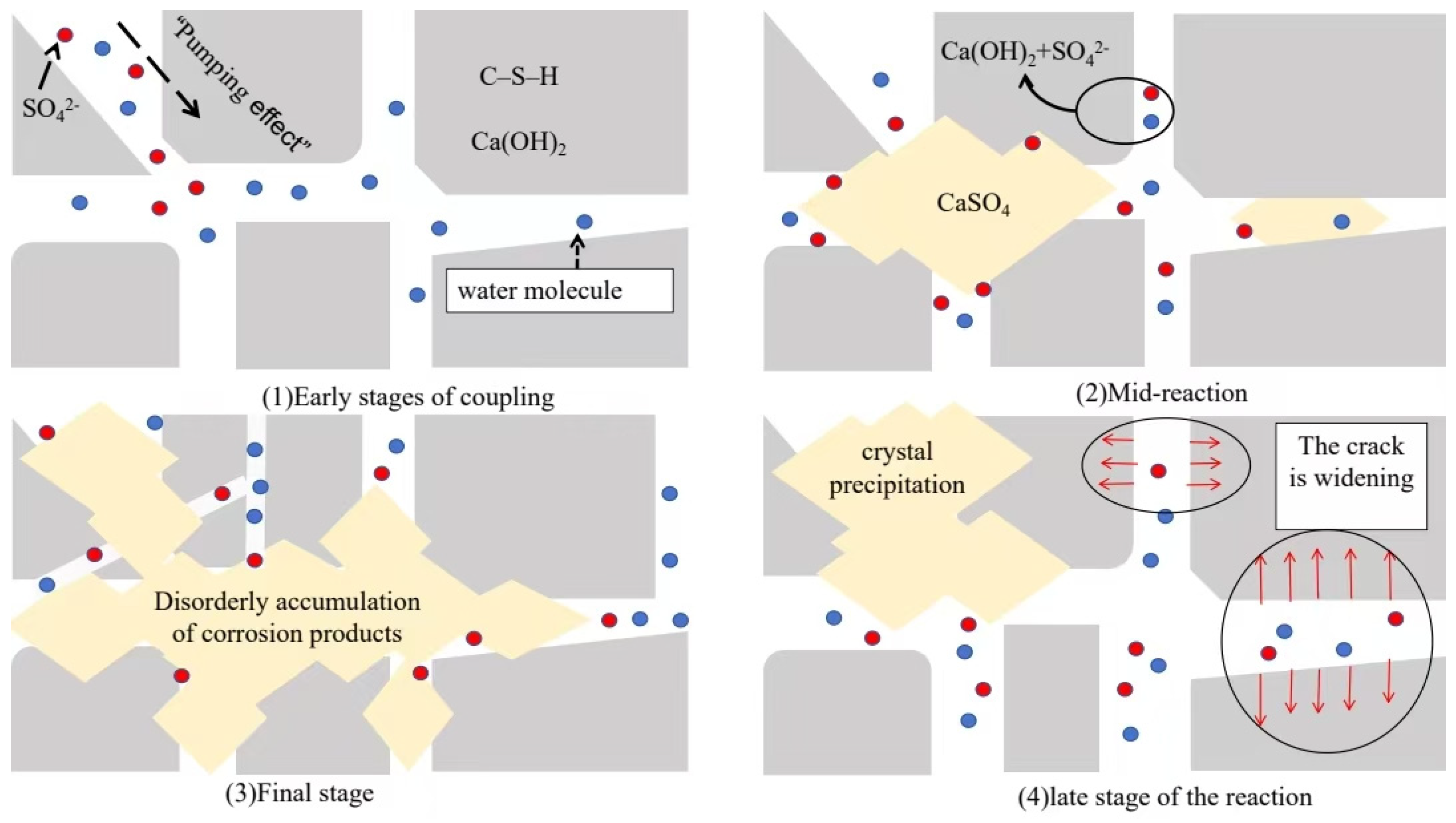
The deterioration of cement-based grouting materials in tunnel inflow fluids is controlled by the coupled effects of corrosive transport, chemical dissolution, crystallization pressure, and dry–wet fatigue. During cyclic exposure, moisture evaporation in the drying stage induces internal suction, while subsequent wetting promotes the ingress of oil components, acidic gases, and saline groundwater into the cementitious matrix, producing a typical pumping effect [46]. The core of the “pumping effect” lies in the following: during the “dry” phase, moisture within the substrate evaporates, causing the capillary meniscus to recede and generating a significant capillary negative pressure within the porous medium; When the system re-enters the “wet” phase, this internal negative pressure transforms into a powerful “suction force”, rapidly “pumping” the external corrosive solution into the substrate at a rate far exceeding that of simple hydrostatic diffusion. At the early stage, continued hydration partly offsets corrosion damage, and the mechanical and impermeability properties change only slightly. With increasing exposure time, acidic components react with Ca(OH)2 and accelerate the decalcification of C–S–H gel, causing pore development, microcrack initiation, and gradual loss of matrix compactness [47]. The coupled damage process and the corresponding inhibition mechanism of epoxy modification are illustrated in Figure 16.
In the later stage, chemical corrosion is further coupled with crystallization-induced expansion and cyclic shrinkage–swelling damage. During repeated drying, the pore solution becomes concentrated, and salt crystallization generates expansive pressure within pores and cracks [48]. Meanwhile, corrosion products accumulate and weaken the bonding capacity of the matrix, promoting the connection of isolated microcracks into continuous fracture networks. As a result, the grouting material exhibits strength reduction, elastic modulus degradation, increased permeability, and eventually powdering or layered spalling.
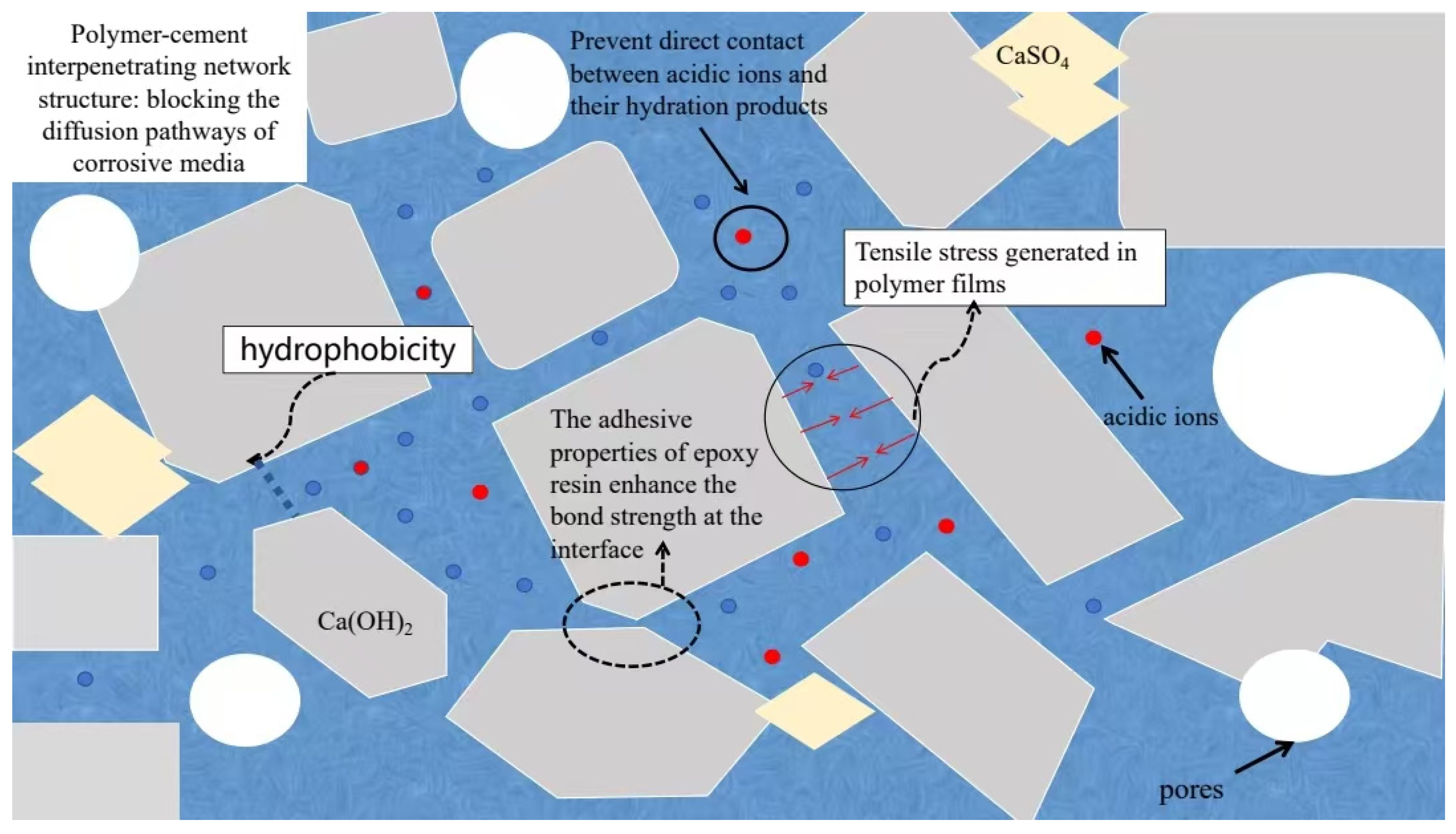
Epoxy modification effectively slows this coupled degradation process. The epoxy phase forms continuous polymer films within the cementitious matrix, fills harmful pores, and blocks the transport channels of aggressive media. Its hydrophobicity weakens the dry–wet cycling-induced pumping effect, while polar functional groups help form a protective layer on Ca(OH)2 crystals and C–S–H gel surfaces, reducing direct contact between aggressive ions and hydration products [49]. In addition, the flexible polymer phase improves interfacial bonding and bridges microcracks, enabling stress redistribution and delaying crack propagation [50]. Therefore, the improved durability of epoxy-modified grouting materials can be attributed to pore refinement, transport blocking, chemical protection, and crack-bridging reinforcement, where organic epoxy components interact with cement hydrates via physical adsorption and partial chemical bonding to regulate hydration progress; the in-depth microscopic coupling mechanism requires further advanced characterization in future research (as shown in Figure 17).
Fundamentally driven by the film-formation mechanism of the waterborne epoxy modifier, the interpenetrating polymer network develops a continuous, hydrophobic barrier that significantly restricts the transport velocity of aggressive SO42− ions through enhanced pore tortuosity. Furthermore, on a micro-mechanical scale, this flexible phase provides a vital crack-bridging effect that dissipates localized energy and retards macro-crack propagation under cyclic fatigue, effectively converting rapid networked fracturing into a decelerated progression as validated by the lower drop in terminal UPV wave velocity.
Figure 17. Evolution of the corrosion damage inhibition mechanism of grouting materials by epoxy resin.
Processes 14 02464 g017

6. Conclusions

This study investigated the durability degradation and modification mechanism of waterborne-epoxy-modified cementitious grouting materials under dry–wet cyclic corrosion in an oil- and gas-bearing corrosive environment. Multi-scale tests and theoretical modeling were used to evaluate mechanical properties, impermeability, internal damage, and microstructural evolution. The main conclusions are as follows:
  • The unmodified grouting material showed a progressive deterioration process under dry–wet cyclic corrosion. After 120 cycles, the impermeability pressure decreased from 0.9 MPa to 0.3 MPa, corresponding to a reduction of 66.7%. This decline occurred earlier and more sharply than the loss of compressive strength and elastic modulus, indicating that in this experimental condition, impermeability is a more sensitive indicator for early damage identification under multiphase corrosive exposure.
  • The macroscopic performance loss was closely associated with microstructural evolution. The consumption of Ca(OH)2 and the accumulation of expansive products, mainly gypsum and ettringite, promoted pore coarsening, crack propagation, and crack network formation. The longitudinal wave velocity decreased by nearly 3000 m/s in the later exposure stage, confirming that nonlinear accumulation of internal defects governed the accelerated loss of stiffness and sealing capacity within the scope of this test.
  • Waterborne epoxy modification effectively improved the resistance of the grout to corrosion-induced degradation. After 120 cycles, the strength and elastic modulus losses of the modified material were limited to 17.4% and 21.0%, respectively, while its impermeability pressure remained about twice that of the unmodified material. This improvement was attributed to the formation of a polymer–cement interpenetrating network, which reduced pore connectivity, limited aggressive media transport, and delayed microcrack propagation in the studied corrosive environment.
  • A degradation model incorporating a critical deterioration threshold was established to describe the post-peak mechanical evolution under the tested different corrosive conditions. The prediction errors were below 8%, indicating good agreement with the test results. In addition, the proposed impermeability grading method can provide a reference for evaluating the durability and sealing performance of cementitious grouting materials exposed to similar complex corrosive environments.

Author Contributions

Methodology, X.Z.; Software, Y.H.; Formal analysis, W.H. and Y.W. (Yu Wang); Data curation, Y.H.; Writing—original draft, B.Y.; Writing—review & editing, B.Y. and Y.H.; Project administration, Y.W. (Yu Wang); Validation, Y.W. (Yukai Wu). All authors have read and agreed to the published version of the manuscript.

Funding

This research received no external funding.

Data Availability Statement

The data presented in this study are available on request from the corresponding author.

Conflicts of Interest

Authors B.Y. and Y.W. were employed by Sichuan Chuanjiao Road and Bridge Co., Ltd. Author X.Z. was employed by Guang’an Transportation Construction Quality Supervision and Management Station. Author W.H. was employed by CCCC First Highway Engineering Group Fifth Engineering Co., Ltd. The remaining authors declare that the research was conducted in the absence of any commercial or financial relationships that could be construed as a potential conflict of interest.

References

  1. Wang, C.; Yan, H.; Deng, T.; Liu, B.; Yang, D.; Tian, F. An Anti-Corrosion Tough Cement Slurry Treated with Self-Crosslinking Epoxy Resin Emulsion. Drill. Fluid Complet. Fluid 2024, 41, 522–530. [Google Scholar]
  2. Kang, H.; Li, W.; Gao, F.; Yang, J. Grouting theories and technologies for the reinforcement of fractured rocks surrounding deep roadways. Deep Undergr. Sci. Eng. 2023, 2, 2–19. [Google Scholar]
  3. Zhang, J.; Liu, L.; Li, Y. Mechanism and experiment of self-stress grouting reinforcement for fractured rock mass of underground engineering. Tunn. Undergr. Space Technol. 2023, 131, 104826. [Google Scholar] [CrossRef]
  4. Huang, S.; Zhao, G.; Meng, X.; Cheng, X.; Gu, Q.; Liu, G.; Zhu, S. Development of cement-based grouting material for reinforcing narrow coal pillars and engineering applications. Processes 2022, 10, 2292. [Google Scholar] [CrossRef]
  5. Li, X.; Lv, W.; Li, M.; Zhang, K.; Xu, Z.; Yuan, J.; Liu, T.; Wang, S.; Fu, A.; Feng, Y. Sulfide stress corrosion cracking in L360QS pipelines: A comprehensive failure analysis and implications for natural gas transportation safety. Int. J. Press. Vessels Pip. 2024, 212, 105324. [Google Scholar] [CrossRef]
  6. Guo, X.; Gu, T.; Li, Z.; Cheng, X.; Zheng, Y. Corrosion mechanism of hydrogen sulfide on cement sheath in wet environments. Nat. Gas Ind. 2015, 35, 93–98. [Google Scholar]
  7. Lu, F.; Zhang, H.; Zhang, Y.; Zou, B.; Wu, H. Optimized mix design and long-term deterioration mechanism of coal gangue concrete under sodium sulfate attack. Constr. Build. Mater. 2026, 530, 146606. [Google Scholar] [CrossRef]
  8. Qin, P.F.; Chen, T.; Zhou, X.Y. Study on Composite Grouting Reinforcement Technology and Its Application in Sandy Tunnels. China Rural Water Hydropower 2025, 147, 136–141. [Google Scholar]
  9. Tang, J. Research on Grouting Construction Technology in Tunnel Advance Pre-reinforcement Engineering. Sci. Technol. Innov. Her. 2020, 17, 20–21. [Google Scholar]
  10. Li, S.; Yuan, B.; Cheng, J.; Yu, X.; Wei, C.; Wu, Q.; Zhang, Y. The influence of nano-SiO2 emulsion on sulfate resistance of cement-based grouts. Materials Science-Poland 2024, 42, 116–125. [Google Scholar] [CrossRef]
  11. Ma, Q.; Li, B. Performance of a New Grouting Material under the Coupling Effects of Freeze-Thaw and Sulfate Erosion. Materials 2023, 16, 5448. [Google Scholar] [CrossRef] [PubMed]
  12. Xie, C.; Wang, Q.; Yu, B.; Zhang, R.; Dai, J.; Guo, Y. Analysis of sulfate corrosion resistance of cement-based composite cementitious materials under different erosion temperatures. J. Mater. Sci. Eng. 2020, 38, 571–578+584. [Google Scholar]
  13. Zhou, M.R.; Cao, R.Z.; Zhou, Q.; He, Y. Experimental Study on Optimizing Strength and Sulfate Corrosion Resistance of Cement-Based Grouting Materials via Response Surface Methodology. Build. Sci. 2019, 35, 101–107. [Google Scholar]
  14. Liu, X.; Zhuang, Y.; Zhou, X.; Zhang, X.; Chen, H. Study on crack grouting and secondary corrosion of tunnel lining with non-through cracks in sulfate environment. Chin. J. Rock Mech. Eng. 2024, 43, 2627–2638. [Google Scholar]
  15. Xu, F.Y.; Yang, W.J.; Yang, J.Y. Erosion Resistance of Masonry Exposed to Dry-Wet Cycles in Organic Acid-Sulfate Mixed Solution. Corros. Prot. 2025, 46, 43–49. [Google Scholar]
  16. Ma, C.L. Study on Durability Deterioration Law and Strength Grade Effect of Shaft Wall Concrete Under Chloride-Sulfate Erosion. Master’s Thesis, Anhui University of Science and Technology, Huainan, China, 2025. [Google Scholar]
  17. Wang, X.; Zhang, L.; Li, H. Influence of co-blending fly ash and ceramic waste powder on the performance and microstructure of cementitious substrates under sulfate dry-wet cycle attack. PLoS ONE 2025, 20, e0314277. [Google Scholar] [CrossRef] [PubMed]
  18. Zhou, Y.; Tian, H.; Sui, L.; Xing, F.; Han, N. Strength deterioration of concrete in sulfate environment: An experimental study and theoretical modeling. Adv. Mater. Sci. Eng. 2015, 2015, 951209. [Google Scholar] [CrossRef]
  19. Zeng, P. Study on Mechanical Properties of Fly Ash Concrete Under Combined Effects of Loading and Sulfate Erosion. Master’s Thesis, Nanchang Institute of Engineering, Nanchang, China, 2025. [Google Scholar]
  20. Xu, Y.; Xiao, J.; Liu, J.; Xia, K. True-triaxial strength characteristics of cement stone subjected to sulfuric acid corrosion: An experimental and theoretical study. Constr. Build. Mater. 2024, 444, 137877. [Google Scholar] [CrossRef]
  21. Zhang, L.; Dzombak, D.A.; Nakles, D.V.; Hawthorne, S.B.; Miller, D.J.; Kutchko, B.G.; Lopano, C.L.; Strazisar, B.R. Characterization of pozzolan-amended wellbore cement exposed to CO2 and H2S gas mixtures under geologic carbon storage conditions. Int. J. Greenh. Gas Control 2013, 19, 358–368. [Google Scholar] [CrossRef]
  22. She, C.; Zheng, Y.; Chen, L.; Fan, Y.; Yang, J.; Cai, J. Corrosion law of cement paste under hydrogen sulfide conditions in natural gas wells. Front. Mater. 2023, 10, 1247086. [Google Scholar] [CrossRef]
  23. Zhang, L.; Dzombak, D.A.; Nakles, D.V.; Hawthorne, S.B.; Miller, D.J.; Kutchko, B.; Lopano, C.; Strazisar, B. Effect of exposure environment on the interactions between acid gas (H2S and CO2) and pozzolan-amended wellbore cement under acid gas co-sequestration conditions. Int. J. Greenh. Gas Control 2014, 27, 309–318. [Google Scholar] [CrossRef]
  24. Mei, K.; Cheng, X.; Pu, Y.; Ma, Y.; Gao, X.; Yu, Y. Evolution of silicate structure during corrosion of tricalcium silicate (C3S) and dicalcium silicate (C2S) with hydrogen sulphide (H2S). Corros. Sci. 2020, 163, 108301. [Google Scholar] [CrossRef]
  25. Yang, Z.J.; Wang, D.; Wu, Z.Q.; Chen, D.Y.; Yao, P.J.; Zhang, H. Comparison Between Hydrogen Sulfide and Sulfuric Acid Corrosion of Oil Well Cement Stone. Drill. Fluids Complet. Fluids 2012, 29, 54–58. [Google Scholar]
  26. Ma, K.H.; Zhou, S.M.; Chu, Y.T.; Tan, C.Q.; Wang, X.J. H2S Corrosion to Cement Stone at High Temperature. Pet. Drill. Technol. 2008, 36, 4–8. [Google Scholar]
  27. Yang, Y.G.; Shi, T.H.; Xie, Y.Q. Experimental Study on Corrosion Mechanism of Cement Sheath for Cementing in Marine Acid Gas Reservoirs. In Proceedings of the 5th International Conference of the State Key Laboratory of Reservoir Geology and Development Engineering, Chengdu, China, 22–23 October 2009; pp. 589–596. [Google Scholar]
  28. Fu, B.; Cheng, Z.Y.; He, Y.T.; Hu, Y.X.; Han, J.Y. Effect of Slag on Thaumasite Sulfate Attack Resistance of Cement Paste. Bull. Chin. Ceram. Soc. 2020, 39, 471–476. [Google Scholar]
  29. Wang, D.; Yang, K.; Zhang, Y.; Liu, C.; Liu, Z.; Ren, J.; Wu, M.; Pang, B. Degradation mechanism of cement paste buried in sulfate-rich saline soil. Case Stud. Constr. Mater. 2025, 22, e04537. [Google Scholar] [CrossRef]
  30. Lü, F. Research on Corrosion Inhibitors for Cementing Slurries in High-H2S Acidic Gas Reservoirs. Master’s Thesis, Southwest Petroleum University, Chengdu, China, 2023. [Google Scholar]
  31. Tan, C.; Wang, M.; Chen, R.; You, F. Study on the oil well cement-based composites to prevent corrosion by carbon dioxide and hydrogen sulfide at high temperature. Coatings 2023, 13, 729. [Google Scholar] [CrossRef]
  32. Zhang, J.; Yu, Z.; Qin, X.; Zhang, H. Study on rheological and mechanical properties of waterborne epoxy resin modified cement grout. J. Funct. Mater. 2025, 56, 8212–8218. [Google Scholar]
  33. He, M.D. Study on Application Performance of Waterborne Epoxy Resin for Oil and Gas Well Cementing. Master’s Thesis, Southwest Petroleum University, Chengdu, China, 2019. [Google Scholar]
  34. Liu, Y.L. Research on Waterborne Epoxy Resin Cement Slurry for Well Cementing. Master’s Thesis, Southwest Petroleum University, Chengdu, China, 2019. [Google Scholar]
  35. Liu, Y.L.; Li, Z.Y.; Xue, Y.T.; Zhou, B.; Sun, H.; Su, D.H.; Sun, J.F. Study on mechanical properties of waterborne epoxy resin cement sheath for cementing. Bull. Chin. Ceram. Soc. 2019, 38, 339–343. [Google Scholar]
  36. Peng, Z.; Lv, F.; Feng, Q.; Zheng, Y. Enhancing the CO2-H2S corrosion resistance of oil well cement with a modified epoxy resin. Constr. Build. Mater. 2022, 326, 126854. [Google Scholar] [CrossRef]
  37. Pang, B.; Jia, Y.; Pang, S.D.; Zhang, Y.; Du, H.; Geng, G.; Ni, H.; Qian, J.; Qiao, H.; Liu, G. The interpenetration polymer network in a cement paste-waterborne epoxy system. Cem. Concr. Res. 2021, 139, 106236. [Google Scholar] [CrossRef]
  38. Pang, B.; Yang, C.; Wang, P.; Tian, L.; Mei, B.; Song, X. Cement-based ductile rapid repair material modified with self-emulsifying waterborne epoxy. J. Build. Eng. 2023, 79, 107864. [Google Scholar] [CrossRef]
  39. Huang, Z. Influence of Waterborne Epoxy Resin on Microstructural Evolution of Cementitious Materials. Master’s Thesis, Wuhan University of Technology, Wuhan, China, 2017. [Google Scholar]
  40. Wang, Y. Preparation and Modification Mechanism of Waterborne Epoxy Resin Modified Composite Grout Material. Master’s Thesis, Wuhan University, Wuhan, China, 2022. [Google Scholar]
  41. GB/T 748-2023; Sulfate Resistance Portland Cement. China Standards Press: Beijing, China, 2023.
  42. JGJ 63-2006; Standard of Water for Concrete. China Architecture & Building Press: Beijing, China, 2006.
  43. GB/T 1346-2024; Test Methods for Water Requirement of Normal Consistency, Setting Time and Soundness of the Portland Cement. China Standards Press: Beijing, China, 2024.
  44. JGJ/T 70-2009; Standard for Test Method of Basic Properties of Construction Mortar. China Architecture & Building Press: Beijing, China, 2009.
  45. GB/T 50082-2009; Standard for Test Methods of Long-Term Performance and Durability of Ordinary Concrete. China Architecture & Building Press: Beijing, China, 2009.
  46. Liu, Y.S.; Pang, J.Y. Mechanical properties and microstructure of hybrid fiber/rubber concrete under sulfate attack. Acta Mater. Compos. Sin. 2024, 41, 2055–2064. [Google Scholar]
  47. Li, F.H.; Huang, S.N.; Xiao, S.; Huo, J.T.; Fan, S.X.; Liu, M.H.; Ding, Y.Q.; Tian, Y. Sulfate resistance of concrete under high temperature and dry–wet cycling in different zones. J. Southwest Jiaotong Univ. 2026, 61, 41–51. [Google Scholar]
  48. Li, Z.; Gu, T.; Guo, X.; Cheng, X. Characterization of the unidirectional corrosion of oilwell cement exposed to H2S under high-sulfur gas reservoir conditions. RSC Adv. 2015, 5, 71529–71536. [Google Scholar] [CrossRef]
  49. Hang, Z.Y.; Jin, X.G.; Luo, W. Long-term behaviors of concrete under low concentration sulfate attack subjected to natural variation of environmental climate conditions. Cem. Concr. Res. 2019, 116, 217–230. [Google Scholar] [CrossRef]
  50. Kim, Y.-S.; Kim, S.-W.; Lee, J.-Y.; Lee, J.-M.; Kim, H.-G.; Kim, K.-H. Prediction of stress-strain behavior of spirally confined concrete considering lateral expansion. Constr. Build. Mater. 2016, 102, 743–761. [Google Scholar] [CrossRef]
Figure 1. Tunnel location and longitudinal section.
Processes 14 02464 g001
Figure 2. Schematic diagram of the specimen preparation process.
Processes 14 02464 g002
Figure 3. Schematic diagram of the dry–wet cycling process.
Processes 14 02464 g003
Figure 4. Experimental setup.
Processes 14 02464 g004
Figure 5. Decline rate in compressive strength under different dry–wet cycle cycles.
Processes 14 02464 g005
Figure 6. Variation in elastic modulus with the number of wet–dry cycles.
Processes 14 02464 g006
Figure 7. Results of impermeability pressure tests of the specimens.
Processes 14 02464 g007
Figure 8. SEM images of the specimens at different numbers of wet–dry cycles: (a) G1—120 times; (b) G2—30 times; (c) G2—90 times; (d) G2—120 times; (e) G3—30 times; (f) G3—120 times.
Processes 14 02464 g008
Figure 9. Evolution of XRD patterns of the specimens subjected to different dry–wet cycles: (a) G2; (b) G3.
Processes 14 02464 g009
Figure 10. Variation in ultrasonic wave velocity of the specimens at different stages of dry–wet cycles.
Processes 14 02464 g010
Figure 11. Ultrasonic waveform variations of the specimens at different numbers of wet–dry cycles: (a) G1—30 times; (b) G1—120 times; (c) G2—30 times; (d) G2—120 times; (e) G3—30 times; (f) G3—120 times.
Processes 14 02464 g011
Figure 12. Validation of the compressive strength model for grouting materials: (a) Relative error of the predicted values; (b) Relationship between residuals and fitted values; (c) Normal Q–Q plot of compressive strength residuals; (d) Comparison between predicted and measured values.
Processes 14 02464 g012aProcesses 14 02464 g012b
Figure 13. Validation of the elastic modulus model for grouting materials: (a) Relative error of the predicted values; (b) Relationship between residuals and fitted values; (c) Normal Q–Q plot of compressive strength residuals; (d) Comparison between predicted and measured values. The proposed prediction models are strictly applicable within the range of 0 to 120 wet dry cycles. Extrapolation beyond 120 cycles has not been experimentally validated and is not recommended without further testing.
Processes 14 02464 g013
Figure 14. Impermeability Grade under various testing conditions.
Processes 14 02464 g014
Figure 15. Predicted service life of grouting materials.
Processes 14 02464 g015
Figure 16. Evolution of the damage mechanism of grouting materials subjected to corrosion by tunnel inflow fluids.
Processes 14 02464 g016
Table 1. Analysis of chemical components in discharge fluids from the Huayingshan Tunnel.
Component TypeCarbon Number Range/Ion SpeciesContentUnitRemarks
Organic componentsC3–C611.28%Including C3(0.32%), C4(0.59%), C5(3.53%) and C6(6.84%)
C7–C1465.34%Maximum C8 content of 26.05%
C15–C204.23%Combined value
C21–C270.67%Combined value
Aromatics17.65%Principal aromatic components
Inorganic ionsSO42-1035.21 mg · L 1
Cl443.68 mg · L 1
Na+817.99 mg · L 1
K+46.84 mg · L 1
Mg2+24.52 mg · L 1
Ca2+28.18 mg · L 1
F7.20 mg · L 1
NO319.25 mg · L 1
Table 2. Chemical composition of the cement.
ItemSiO2Al2O3K2ONa2OFe2O3MgOCaOLOI
Content (%)22.43.970.430.35.271.9962.830.45
Table 3. Experimental groups and working conditions.
GroupCondition NameAqueous Epoxy Resin Dosage (wt.%)Wetting–Drying Cycle Medium
G1Control groupDeionized water
G2Corrosion groupOriginal tunnel discharge fluid
G3Modified group7.0Original tunnel discharge fluid
Table 4. Compressive strength and elastic modulus of grouting materials under different conditions.
GroupCyclesCompressive Strength (MPa)Mean (MPa)Standard DeviationElastic Modulus (GPa)Mean (GPa)Standard Deviation
G1037.59/36.87/37.7537.40.46837.52/37.98/38.0037.80.272
3039.13/37.13/37.1237.81.15837.65/37.83/38.0237.80.185
6038.06/37.15/35.7837.01.14834.68/35.12/35.2035.00.280
9036.92/35.83/35.8336.20.62932.75/33.18/33.0733.00.223
12036.75/34.47/34.6735.31.26332.23/32.61/32.6632.50.235
G2038.44/36.56/37.2037.40.95637.04/37.80/38.9337.80.951
3039.06/38.59/37.8538.50.61032.59/33.94/34.9433.61.179
6036.91/36.10/34.8736.11.02726.43/26.57/27.2326.70.428
9032.16/31.38/30.6531.40.75523.03/23.50/23.9723.50.470
12026.75/26.08/25.7726.20.50120.78/21.00/21.8421.20.561
G3036.52/36.18/36.2036.30.19137.12/36.01/36.6736.60.558
3036.85/36.51/36.7436.70.17435.98/34.72/35.2035.30.636
6035.67/35.32/35.5135.50.17532.85/31.65/32.1032.20.606
9033.15/32.88/33.0033.00.13530.71/29.55/30.0430.10.582
12030.12/29.85/30.0330.00.13729.54/28.30/28.8628.90.621
Table 5. Classification criteria for impermeability grades.
Impermeability GradeCore CriteriaSupplementary Criteria
Grade I Pressure   retention   rate     60 % ,   impermeability   pressure   0.6 MPa Initial   impermeability   pressure   1.2 MPa
Grade II Pressure   retention   rate   45%, impermeability   pressure   0.5 MPa Initial   impermeability   pressure   0.9 MPa
Grade III Pressure   retention   rate     40 % ,   impermeability   pressure   0.3 MPaInitial impermeability pressure: 0.6–0.9 MPa (excluding 0.9 MPa)
Grade IVImpermeability pressure after 120 wetting–drying cycles < 0.3 MPa; or retention rate < 40% Initial   pressure   <   0.6   MPa ;   or   initial   pressure   0.6 MPa but pressure after 120 wetting–drying cycles < 0.3 MPa; or retention rate < 40%
Disclaimer/Publisher’s Note: The statements, opinions and data contained in all publications are solely those of the individual author(s) and contributor(s) and not of MDPI and/or the editor(s). MDPI and/or the editor(s) disclaim responsibility for any injury to people or property resulting from any ideas, methods, instructions or products referred to in the content.