Article

Modeling and Optimization of a Green Ammonia Synthesis Loop Across a Wide Production Load Range

1
School of Chemical Engineering, Sichuan University, Chengdu 610065, China
2
China Petroleum Engineering & Construction Co., Ltd., Southwest Branch, Chengdu 610095, China
*
Authors to whom correspondence should be addressed.
Processes 2026, 14(13), 2055; https://doi.org/10.3390/pr14132055
Submission received: 30 April 2026 / Revised: 11 June 2026 / Accepted: 18 June 2026 / Published: 24 June 2026
(This article belongs to the Section Chemical Processes and Systems)

Abstract

“Power-to-ammonia” is widely regarded as a viable solution for large-scale consumption of wind and solar power, as well as for deep decarbonization in the energy and chemical sectors. However, the intermittent nature of renewable energy requires ammonia synthesis systems to operate across a wide and varying range of loads, posing challenges to their economic viability. To address this, we develop a simulation and optimization methodology for ammonia reactor operation under varying loads. Firstly, a high-fidelity reactor model is developed based on the reactor’s structural characteristics by incorporating reaction kinetics and thermodynamic mechanisms. This reactor model is then integrated with compression and separation units. To ensure computational efficiency, surrogate models are developed to approximate the ammonia synthesis and flash separation units. A case study of an ammonia plant with a nominal production rate of 100,000 tons/year is conducted to demonstrate the effectiveness of the proposed method. The results indicate that the feasible operation region of the reactor narrows significantly as the system production load decreases. System operation parameters, including reactor inlet temperature, reactor pressure, and ammonia separation temperature, are optimized for the ammonia synthesis loop over a wide operating window from 30% to 100% of nominal capacity. It is recommended to increase the system inlet temperature as the production load decreases, thereby compensating for the reduced heat release per unit product resulting from the decreased system pressure.

1. Introduction

The extensive reliance on fossil fuels has resulted in substantial greenhouse gas emissions, a primary driver of global climate change. This phenomenon has not only emerged as one of the most widely debated environmental issues worldwide but also poses one of the most severe challenges to global sustainable development [1]. Decarbonization of the industrial sector is of strategic importance under this circumstance [2]. Integrating renewable energy sources (e.g., wind and solar power) offers a promising route for chemical process systems to reduce their dependence on fossil fuel-based energy supply, and thus in turn reduces carbon emissions. As such, this approach is broadly recognized as a key strategy for achieving decarbonization within the chemical industry [3]. Nevertheless, the inherent intermittency and seasonal variability of renewable resources hinder their direct integration, due to the mismatch between energy supply and demand across multiple time scales. To tackle this, energy storage is considered essential [4,5].
Among the many forms of energy storage (mechanical, thermal, electrochemical, and chemical), chemical is regarded as one of the most promising for large-scale, long-term storage of intermittent renewable energy. Hydrogen, ammonia, and methanol are all considered viable and widely investigated. As the most direct renewable energy carrier, hydrogen plays an important role as a renewable energy carrier in the energy sector. Yet, it is generally not employed for long-term storage, due to its relatively high storage and transportation costs [6]. Ammonia, as a non-toxic carbon-free hydrogen carrier, has attracted extensive attention owing to its relatively high volumetric energy density [7], widespread use in agriculture [8,9], and ease of distribution with well established storage and transportation qualities [10,11,12].
The most mature route for large-scale ammonia production is the Haber–Bosch process. This process requires high temperature and pressure to maintain catalyst activity, which makes the integration of fluctuation renewable energy more difficult. Although various new approaches have been investigated for ammonia production, such as chemical looping [13], photocatalytic [14], and electrochemical synthesis [15], these techniques are currently not commercially unviable [16]. Consequently, significant attention has been given to overcoming the flexibility bottleneck of the power-to-ammonia system, namely, the Haber–Bosch synthesis loop, by adapting it to the fluctuating nature of renewable energy.
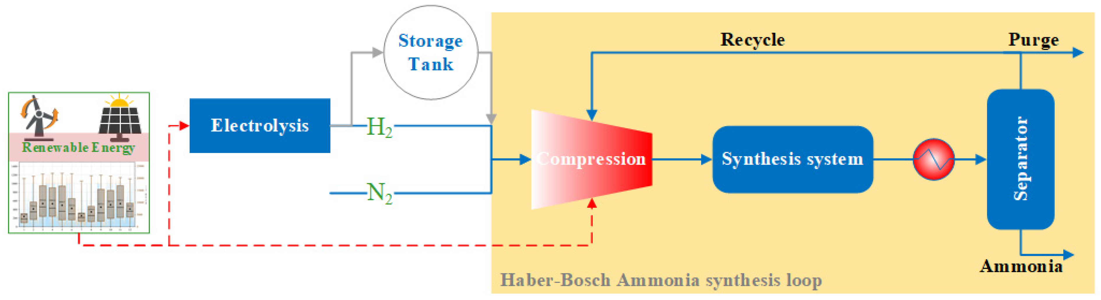
Figure 1 illustrates a simplified power-to-ammonia concept. Hydrogen produced via water electrolysis is mixed with on-site produced nitrogen, and the obtained syngas is subsequently compressed prior to entering the Haber–Bosch synthesis loop. Within the reactor, ammonia is formed. It is then separated by condensation, and the unreacted gases are recovered and recirculated back into the loop [17].
The intermittent and fluctuating nature of renewable power leads to an unstable supply of green hydrogen, preventing the green ammonia synthesis loop from operating continuously. This challenge is common across various power-to-X processes, where X can be methanol or methane. Studies indicate that incorporating a hydrogen buffer tank is essential for such systems to improve economic viability and ensure operational safety [18]. It should be noted that while hydrogen storage is generally cheaper than battery-based electricity storage, large-scale storage of hydrogen is still much higher than that of ammonia [19]. Conventionally, a large-scale ammonia synthesis plant cannot maintain high system efficiency at low production load, making the operation of the Haber–Bosch synthesis loop the bottleneck of flexible green ammonia production [20].
Previous research on process operation and control has focused on identifying manipulation strategies that improve system stability and achievable flexibility under a fixed system configuration. Morud et al. [21] highlighted an incident in an industrial ammonia fixed-bed synthesis reactor in Germany. They stressed that oscillatory behavior may occur if fluctuations in feedstock conditions were not properly handled. Stephens et al. [22] reported that dynamic operation of the ammonia synthesis loop is significantly affected by variations in the H2/N2 ratio or by disturbances in the inlet feed and temperature. Accordingly, Cheema and Krewer [23,24] investigated the effects of varying H2/N2 ratios, argon concentration, and mass flow rate, along with five different reactor designs, to enhance the operational and production flexibility of ammonia under steady-state conditions. Subsequently, Fahr et al. [25] optimized the ammonia reactor design to enhance the system load flexibility, and a 41–48% reduction in the minimum feasible load is achieved. Verleysen et al. [26] developed a model of a Haber–Bosch loop featuring a single adiabatic bed and examined how the system responds to external disturbances and load variations (50–100%). According to their findings, the plant becomes more sensitive to disturbances as the load increases. Additionally, the reactor inlet temperature primarily determines the plant’s behavior under high-load conditions, whereas the H2/N2 ratio plays the dominant role at low loads. Recently, a strategy for optimally varying feed flow rates under flexible ammonia reactor operation was developed by Rosbo et al. [27], which was then implemented alongside a controller to achieve regulation of the system between optimal set points. A number of patents were also introduced to enable frequent load changes in the ammonia loop, such as maintaining high synthesis pressure via compressor flow regulation valves to control re-circulation gas flow [28], accumulating inert gases within the loop [29], and adjusting the H2/N2 ratio [30,31,32,33,34]. Additionally, research efforts have also been paid to the reduction in NOx emissions in the use of ammonia as an energy source [35,36].
Despite considerable progress in power-to-ammonia systems over the past decade, the optimal operation of the synthesis loop remains inadequately addressed. In particular, the feasible operation region under different production loads is rarely investigated. To address this gap, a modeling and operation optimization method is developed for a green ammonia synthesis loop across a production load range of 30–100%. The remainder of this study is structured as follows. Section 2 presents the simulation and optimization model developed for the ammonia synthesis loop, followed by an introduction to the case study in Section 3. Results and discussion are given in Section 4, and the conclusions are derived in Section 5.

2. Simulation and Optimization Model for Ammonia Synthesis Loop

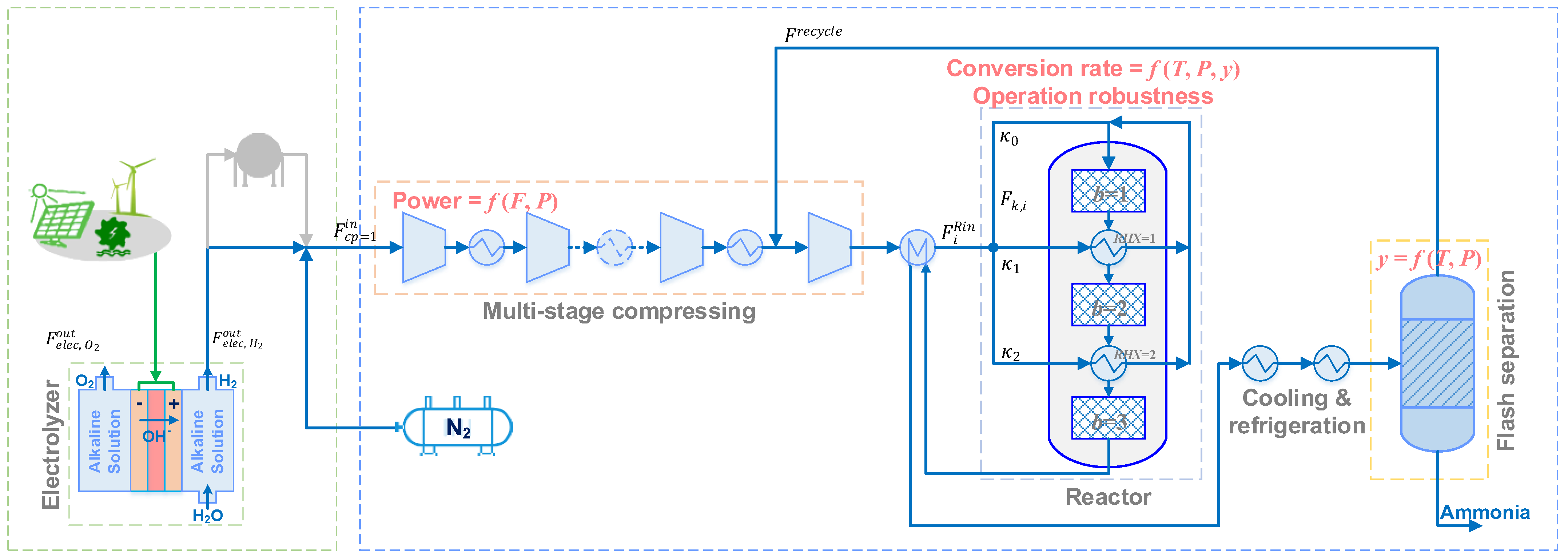
In this section, the green ammonia synthesis system is modeled as follows. As shown in Figure 2, the system consists of the following subsystems: an alkaline water electrolysis unit, a multistage compression unit, a Haber–Bosch reactor, and a flash separation unit. For each subsystem, both first-principle and data-driven surrogate models are developed.

2.1. Alkaline Water Electrolysis Unit

Hydrogen is generated via alkaline water electrolysis. The hydrogen production rate is calculated using Faraday’s efficiency, as shown in Equations (1) and (2), and the by-product oxygen production rate is given by Equation (3) [37].
η = i 2 f 11 + f 12 · T 273.15 + i 2 · f 21 + f 22 · T 273.15
F H 2 = η · i · A c e l l Z · F a r a · S · 3.6
F O 2 = 1 2 · F H 2
where i denotes the current density, η is Faraday’s efficiency, T is the operation temperature, and f11, f12, f21, f22 represent the parameters derived from experimental data. F is the molar flow rate, A c e l l and Z represent the active electrode area and electrons transferred per ion, and S and F a r a are the number of cells for the stacks and Faraday’s constant. The full set of calculation formulations, parameter values, and their sources are detailed in the Supplementary Materials.

2.2. Multistage Compression

Normally, ammonia synthesis takes place under high-pressure conditions (15–30 MPa) in order to maintain catalyst activity [24]. Therefore, a multistage compressor is installed to pressurize the raw material flow before it enters the reactor. The same compression ratio is typically used for each stage, and interstage coolers are employed to remove the heat generated during compression. In this way, the power consumption of the compression process can be reduced. The raw material flow consists of hydrogen from the water electrolysis unit and nitrogen produced on-site, which are mixed according to certain proportions. The molar ratio of H2-to-N2, r, is an important operation parameter for ammonia synthesis, especially in the case of green ammonia production. Let C denote the compression stage of the raw material compressing process. The inlet flow rate of the first stage compressor is calculated by Equation (4), and the last stage compressor inlet flow rate is calculated by Equation (5). As given, the inlet flow rate of the first stage compressor equals to the summation of hydrogen flow and nitrogen flow, while the inlet of the last stage compressor takes the recycling stream with the unreacted hydrogen and nitrogen and the outlet of the previous stage.
F c p i n = F H 2 · 1 + 1 r c p = 1
F c p i n = F c p 1 o u t + F r e c y c l e c p = C P
The power consumption and the cooling loads of the compression process is calculated by the process energy balance. Equation (6) calculates the power consumption of a compressor, while Equation (7) computes the outlet temperature after the compression [38]. In practice, the inlet temperature of a multistage compression process is normally kept the same, in order to enhance the energy efficiency of the procedure. Hence, interstage coolers are usually employed, and the cooling load is calculated by Equation (8).
P O W E R c p = 1.634 · 1.01971 · P c p i n · V c p i n 60 · η ^ c p · γ γ 1 · P c p o u t P c p i n γ 1 γ 1   c p C P
T c p o u t = T c p i n · P c p o u t P c p i n γ 1 γ c p C P
Q c p = C p · T c p o u t T c p i n · F c p , n i n · M w n     c p C P , n N
where cp denotes the compressor, V i n represents the volumetric inlet flow rate, and P c p i n ,   P c p o u t are the corresponding inlet and outlet pressures. η ^ is the compressor efficiency, and γ is the polytropic constant. MW and C p are the molecular weight and the specific heat capacity for the gas mixture. For brevity, the mass balance of the inlet and outlet of each compressor, the connection between the middle-stage compressors, and the component mass balance are omitted here.

2.3. Haber–Bosch Reaction Unit

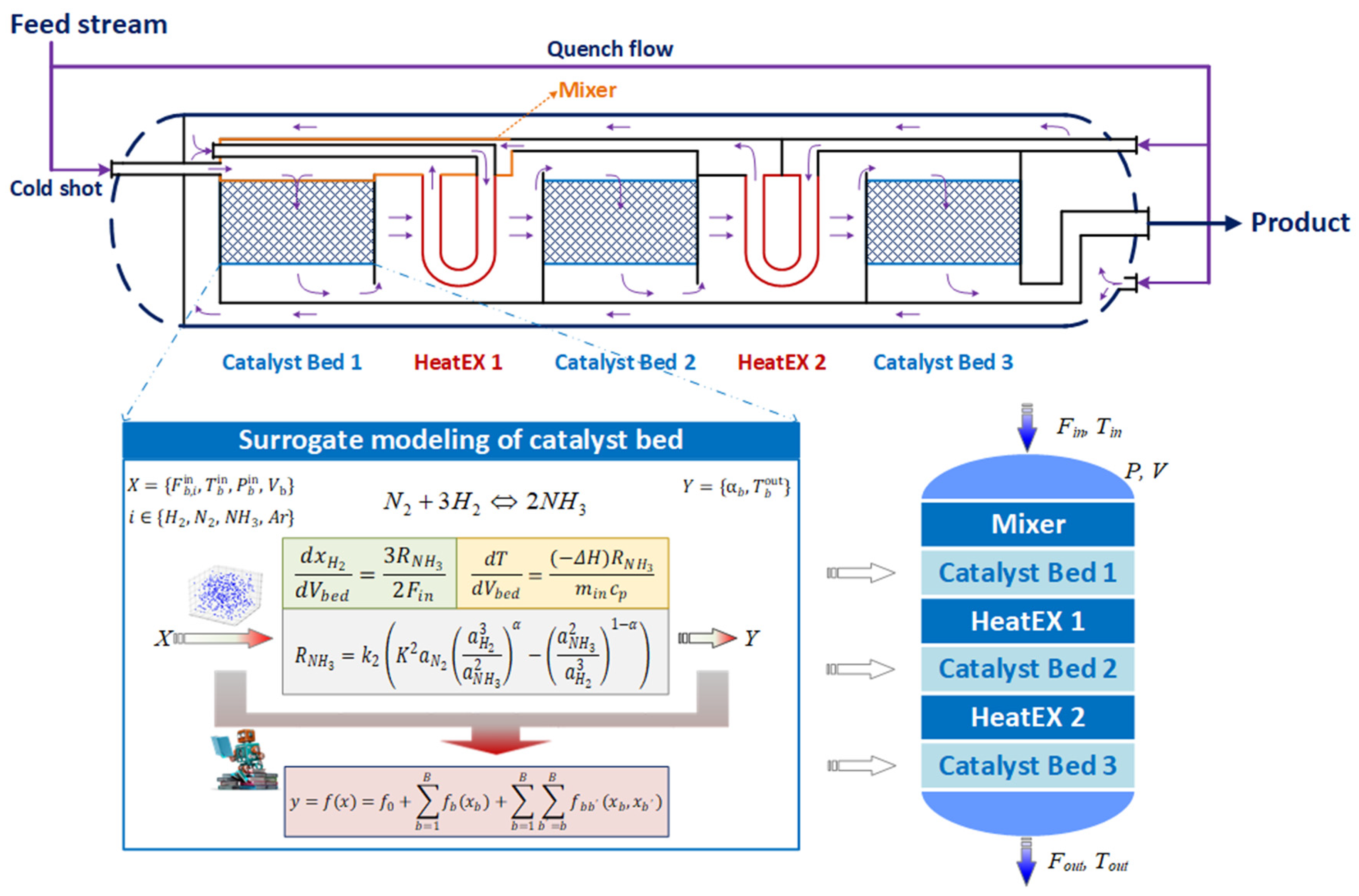
The reactor is the core of an ammonia production system, and the catalyst bed is its heart. The three-bed reactor with intercoolers is studied in this study. According to Khademi and Sabbaghi [39], it is the most favorable among adiabatic bed reactors. The detailed design is illustrated in Figure 3, which follows the KBR technology [40]. As shown, the reactor can be considered as three adiabatic catalyst beds, two heat exchangers (intercoolers), and one mixer, all housed inside a pressure shell. Before entering the reactor, the feedstock is split into three streams, two quench flows, and a cold shot stream. One of the quench streams is directly sent to the intercooler between the second and the third catalyst beds (HeatEX 2) for heat exchange, while the other quench stream first cools the reactor shell by running along the shell before entering the intercooler between the first and the second catalyst beds (HeatEX 1). In this work, heat exchange between the catalyst beds and the quench stream is neglected. After heat exchange with the reaction effluents, the two quench flows are mixed with the cold shot stream, after which the mixture enters the first catalyst bed. Flow rate control of the cold shot stream and the quench streams is important to ensure proper temperature distribution in the catalyst beds. Mass balance of the stream splitting is given as follows.
F k , i = κ k · F i R i n   k ϵ { 0 ,   1 ,   2 } ,   i { N 2 , H 2 , N H 3 , A r }
k κ k = 1   k ϵ { 0 ,   1 ,   2 }
where i denotes the reactants, k denotes the splitting flow before entering the reactor, and κ k represents the splitting ratio of the inlet flow directed to the first stage catalyst bed ( k = 0), the intercooler between the first and second catalyst bed ( k = 1), and the intercooler between the second and third catalyst bed ( k = 2).
The exothermic ammonia synthesis reaction takes place at the surface of the catalyst, where hydrogen and nitrogen are consumed to form ammonia. The mathematical model of the ammonia synthesis reactor consists of three parts, the catalyst beds, the intercoolers, and the mixer.
Catalyst beds
In this study, radial flow catalyst beds are considered, and isobaric and adiabatic conditions are assumed. The steady-state mass and energy balance in the catalyst beds are calculated by the following equations [24]:
d X b , i d V b = ν i · R N H 3 , b 2 · F b , i i n     i { N 2 , H 2 , N H 3 } , b { 1 ,   2 ,   3 }
d T b d V b = ( Δ H b ) · R N H 3 , b m b · C p b   b { 1 ,   2 ,   3 }
R N H 3 , b = k · K 2 · a N 2 · a H 2 3 a N H 3 2 0.5 a N H 3 2 a H 2 3 0.5
m b = i F b , i · M W i   b { 1 ,   2 ,   3 }
where b refers to the catalyst beds, ν i is the stoichiometric of i in the ammonia synthesis reaction, X b , i is the fractional conversion of the corresponding reactant i in catalyst bed b, Vb is the volume of catalyst bed b, R N H 3 , b is the reaction rate in catalyst bed b, F b , i i n is the molar flow rate of the reactant i that enters the catalyst bed b, Tb represents the temperature of the reacting mixture in catalyst bed b, H b is the heat of reaction in catalyst b, m b stands for the total mass flow rate of the reaction mixture, and Cp denotes the specific heat of the reacting mixture. a i , k , and K are activity coefficients for reactant i; the reverse reaction and equilibrium constant of reaction, M W i is the molecular weight of material i. For the calculation of the reaction rate, heat of the reaction, and specific heat of the reaction mixture, the model reported by Cheema and Krewer [24] is employed.
Given the high non-linearity degree of the kinetic and thermodynamic mechanism equations, surrogate models are developed to approximate the ammonia synthesis process, in order to alleviate the computational burden. According to our previous study, HDMR (High-Dimensional Model Representation) is sufficient in modeling the complex physicochemical transformation behavior in chemical production systems [41]. In this study, a second-order polynomial is constructed to approximate the hydrogen conversion rate α b and the outlet temperature of the catalyst bed T b o u t . The form of the employed polynomial is given in the following equations.
α b = g 0 + n = 1 N g n x n + n = 1 N n = n + 1 N g n n x n ,   x n     b   ϵ   { 1 ,   2 ,   3 }
T b o u t = h 0 + n = 1 N h n x n + n = 1 N n = n + 1 N h n n x n ,   x n     b   ϵ   { 1 ,   2 ,   3 }
where n denotes the input variables chosen for the surrogate modeling of the catalyst beds, covering the molar flow rate of each reactant, temperature and pressure, and the volume of the corresponding catalyst bed. The inlet and outlet mass balance of the ammonia reactor is then formulated as follows.
F b , H 2 o u t = F b , H 2 i n · 1 α b     b   ϵ   { 1 ,   2 ,   3 }
F b , i o u t = F b , i i n + ν i · α b · F b , H 2 i n ν H 2   b   ϵ   { 1 ,   2 ,   3 } , i { N 2 , N H 3 }
Heat exchanger
The intercoolers between the catalyst beds are equivalent to heat exchangers (HeatEX 1 and HeatEX 2), where the hot stream passes through the shell and the cold stream flows through the tube side. It is assumed that (i) the reactor is adiabatic, (ii) phase transitions do not occur, and (iii) temperature change only takes place in the axial direction. To balance computational complexity with result accuracy, it is assumed that changes in the thermal properties of the gas streams are neglected. Furthermore, it is also assumed that a chemical reaction does not take place outside the catalyst beds. Therefore, the energy balance of the feed-effluent heat exchanger is calculated by an ε-NTU equation based on the efficiency parameter ε [21]. The outlet temperature of the tube side is determined by the following equation.
T k o u t = ε R H X = k · T b = k o u t + 1 ε R H X = k T R i n   k = { 1 ,   2 }
where subscript k denotes the split stream at the reactor inlet, while RHX stands for the heat exchanger after the corresponding catalyst beds, respectively. Constant ε reveals the effectiveness of the heat exchanger. It is independent of change in the stream temperature and is determined by the configuration of heat exchanger. Equation (20) gives the calculation of the efficiency parameter.
ε R H X = 2 1 + C R H X + 1 + C R H X 2 · 1 + e x p N T U R H X · 1 + C R H X 2 1 e x p N T U R H X · 1 + C R H X 2
where C R H X is the heat capacity ratio, and NTU denotes the number of transfer units. Equations (21) and (22) give the calculation of the heat capacity ratio and the number of transfer units, respectively.
C R H X = m R H X c o l d · C p c o l d m R H X h o t · C p h o t
N T U R H X = U · A R H X m R H X c o l d · C p c o l d
The energy balance of the heat exchanger is formulated as follows, from which the outlet temperature of the shell side can be derived.
T k o u t T k i n · C p k · m k = T b o u t T b + 1 i n · C p b · m b k { 1 ,   2 } ,   b = k
m k = i F k , i · M W i     i { H 2 ,   N 2 ,   N H 3 ,   A r }
Mixer and the connection equations
Assuming ideal and instantaneous gas mixing, the energy balance of the gas mixing at the inlet of the first catalyst bed is formulated as follows. The mass balance is omitted here.
T b = 1 i n = k = 1 2 T k o u t · m k + T R i n · m k = 0 i F i R i n · M W i

2.4. Ammonia Refrigeration System

In the practice of synthetic ammonia production, the formed ammonia is usually separated from the reaction effluent (mixture of ammonia, hydrogen, and nitrogen) by the means of refrigerated condensation. The ammonia content in the gas phase of the reaction effluent after cooling plays a crucial role in determining the production capacity of the ammonia synthesis reactor. One of the key strategies to enhance the ammonia production is to reduce the ammonia content in the inlet gas of the ammonia synthesis reactor. In other words, the inlet ammonia concentration of the reactor is an important operation parameter to be controlled during system operation. The ammonia content at the reactor inlet is determined by the gaseous outlet of the ammonia flash separation unit, which depends on the outlet temperature and pressure of the ammonia refrigeration system. Herein, the pressure is, to some extent, determined by the multistage compression system, while the temperature is determined by the ammonia refrigeration. The energy load of the ammonia refrigeration can be calculated by the following equation.
Q c o o l = C p · ( T R o u t T s p = 1 i n ) · n F R ,   n o u t · M W n

2.5. Flash Separation Unit

Flash separation is a critical unit for the metabolism of the ammonia synthesis loop, which separates the produced ammonia from the unreacted reactants. The product stream is then sent to the downstream refining unit, while the unreacted reactants are cycled back to the reactor. The operation temperature and pressure of the flash separation is of great importance for the synthesis loop in terms of the energy consumption as well as ammonia yield. Modeling of the flash separation unit with high fidelity and low computational cost is important for system optimization. Given that a first-principle model of the flash separation process involves iterative calculation and validation for the gas–liquid equilibrium under certain temperature and pressure, which will pose significant obstacles to the subsequent mathematical optimization procedure, a surrogate modeling technique is employed to approximate the flash separation mechanism.
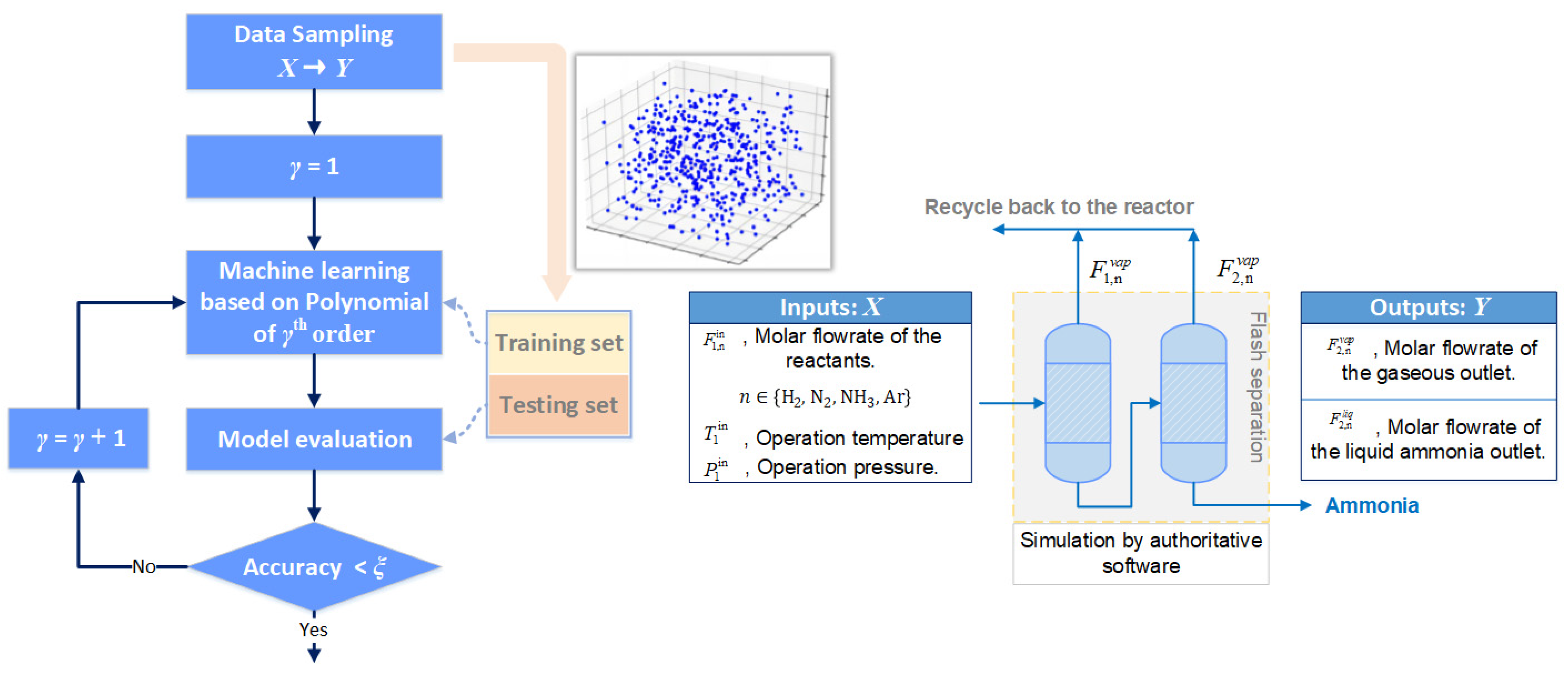
As shown in Figure 4, the cooled reaction effluent is sent to a two-stage flash separation unit. The gaseous outlet stream mainly consisting of the unreacted hydrogen and nitrogen is recycled back to the reactor inlet to improve the efficiency of material usage, while the liquid stream containing product ammonia is sent to a storage tank or for further refinement. Six key operational variables (including the inlet molar flow rate of the reactants as well as the temperature and pressure) are set as the input variables (denoted as X ¯ ), and eight process variables (covering the molar flow rate of the components in gaseous and the liquid outlet stream of the second separation stage) are chosen as the output variables (denoted as Y ¯ ) for the surrogate model development. Possible operation ranges of the six input variables are determined based on system analysis and engineering experiences. The sampled X ¯ datasets are then used as inputs for the simulation model to obtain the corresponding Y ¯ values. A total of 500 sampled data pairs [ X ¯ Y ¯ ] are divided into a training set and a testing set at a ratio of 8:2. The training set is used for model development, while the testing set is used for validation. The mass balance of the flash separation unit is given as follows.
F s p = 1 , i v a p = F s p = 1 , i i n F s p = 2 , i v a p F s p = 2 , i l i q     i { H 2 ,   N 2 ,   N H 3 ,   A r }

2.6. Differential Evolution-Based Optimization of Operating Parameters

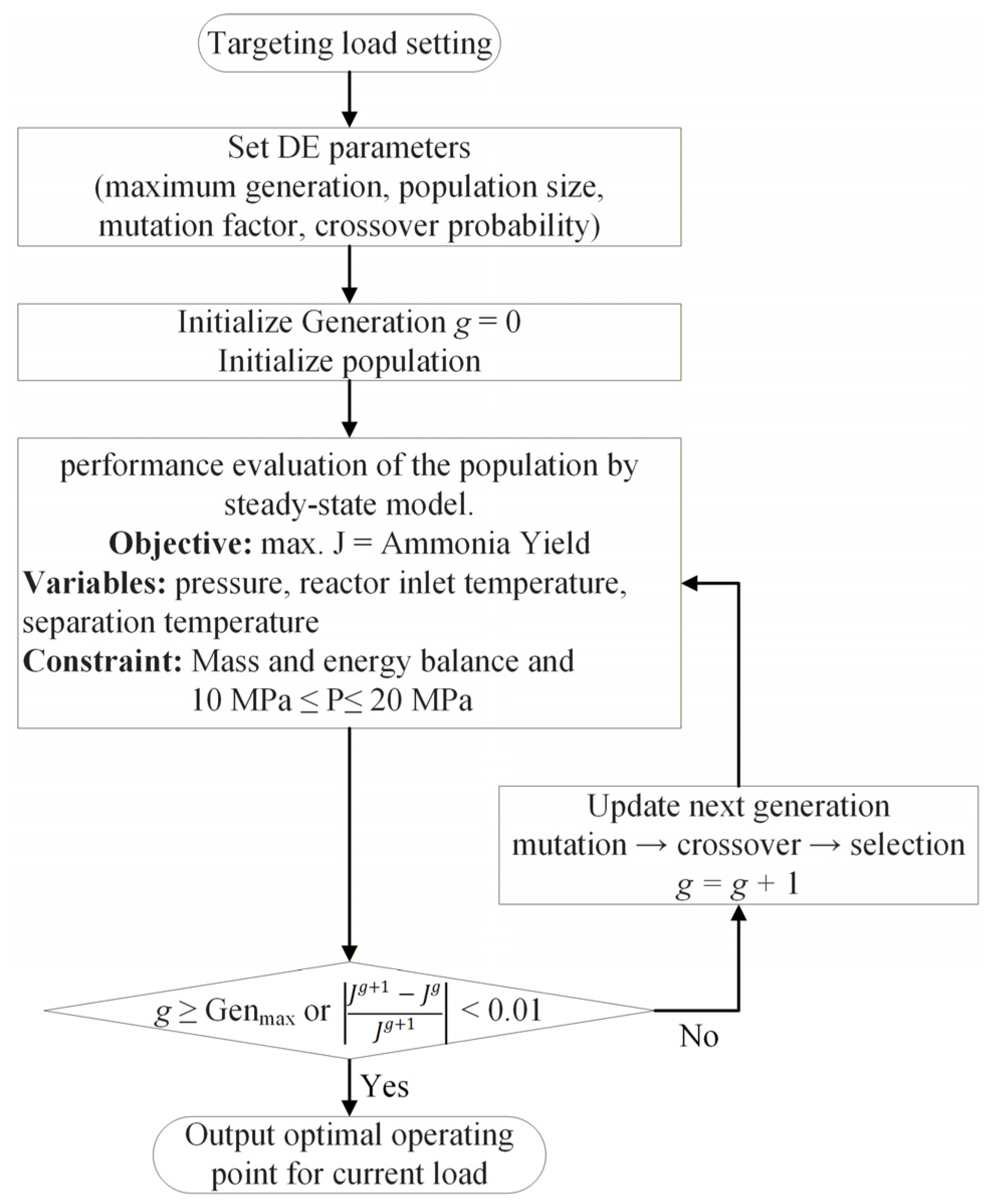
To determine the optimal operating conditions of the ammonia synthesis loop under different production loads, a differential evolution (DE) algorithm is employed to optimize the operation parameter across different production loads. For each specified production load, the steady-state synthesis loop model is used as the process evaluator, and the ammonia production rate is selected as the optimization objective. The optimized operating variables include the system pressure, represented by the reactor pressure, the reactor inlet temperature, and the ammonia stripping temperature. The overall optimization procedure is illustrated in Figure 5. For each production load, the DE algorithm is independently executed to obtain the corresponding optimal operating point.
For a given production load L, the optimization objective is to maximize the net ammonia yield of the synthesis loop:
Max .   A m m o n i a   Y i e l d   = F N H 3 o u t F N H 3 R i n
where F N H 3 o u t and F N H 3 R i n represent the outlet and inlet molar flow rates of ammonia in the synthesis loop, respectively. This definition evaluates the net ammonia generation in the loop rather than the absolute ammonia flow rate of a single stream.
During optimization, each candidate operating point in the DE population is evaluated by the steady-state synthesis loop model. The corresponding net ammonia yield and feasibility of the operating point are then determined. If the convergence criterion or the maximum generation number is reached, the best feasible individual is selected as the optimal operating point for the current production load. Otherwise, the population is updated through DE operations and re-evaluated in the next generation.
The DE algorithm searches the optimal operation parameters in the operating space through population-based mutation, crossover, and selection. In this work, the maximum number of generations is set to 20, and the population size is set to 30. The mutation factor is selected within the range of 0.3–0.7, the crossover factor is set to 0.6, and a fixed random seed is used to ensure reproducibility. Parallel computation is adopted to accelerate the evaluation of candidate operating points.

3. Case Study

In this section, the proposed methodology is applied to a case study to illustrate its effectiveness. The targeted ammonia plant is located in Southwest China, with an annual production capacity of 100,000 tons. Based on the plant configuration, the equipment configuration of the ammonia synthesis system for the case study is given in Table 1. For the ease of calculation, the splitting ratios of the two quench flows are fixed ( κ 1 = 0.4 and κ 2 = 0.5 ). In this case study, the heat exchange area is uniformly set to 60.32 m2 for each of the following heat exchange equipment: the coolers associated with the multistage compression unit, the intercoolers between catalyst beds, the reactor inlet–outlet heat exchanger, the final cooler, and the condenser. The reaction effluent is cooled to 30 °C before entering the refrigeration unit. For surrogate model development, the HDMR models previously trained and validated by our research group [42] were directly adopted, as the same case study with identical system configurations was used. To generate sufficient datasets for training and testing, a first-principle reactor model was developed in MATLAB R2022b, while the ammonia separation process was simulated using UniSim. A total of 500 datasets were generated within the defined operation space, spanning from 30% to 100% of the nominal load. For further details regarding the training and testing datasets, as well as the accuracy and residuals of the surrogate models, please refer to our previous work [42].
The objective is to identify desirable operation parameters to facilitate the load regulation, and in the meanwhile, ensure system stability and enhance profit. Differential evolution was adopted because it can handle the non-linear, simulation-based optimization problem without requiring gradient information and can search for feasible operating conditions through population-based mutation, crossover, and selection. In the scenario of renewable-driven ammonia production, it is demanded that the ammonia synthesis loop adjust its production loads in time to accommodate the shortage and/or abundance of renewable hydrogen supply. Given the frequency and amplitude that the renewable energy may fluctuate, it is almost certain that load adjusting would become routine for the ammonia synthesis loop, if the system were to be operated economically. This brought new challenges to the surface. Specifically, ammonia synthesis is a reaction with a drastic reduction in volume (one mole of nitrogen reacts with three moles of hydrogen to produce two moles of ammonia), which makes pressure control of the system delicate, especially when the system needs to reduce its production load. Load regulation is achieved via decreasing or increasing fresh feed, which may easily lead to reactor pressure fluctuation. Pressure plays a crucial role in maintaining catalyst activity, affecting the reaction conversion rate, which in turn acts upon the system thermal equilibrium. In other words, inappropriate operation of the reactor during load regulation would easily result in instability of the system, which further leads to extinction or limit-cycle behavior of the reactor [21]. The arise of limit-cycle behavior or undesired shutdown of the synthesis reactor can be dangerous as it may cause consistent damage to the reactor and the catalyst [43].

4. Result and Discussion

4.1. Feasible Operating Analysis for the Inlet Flow Split Under Different Production Loads

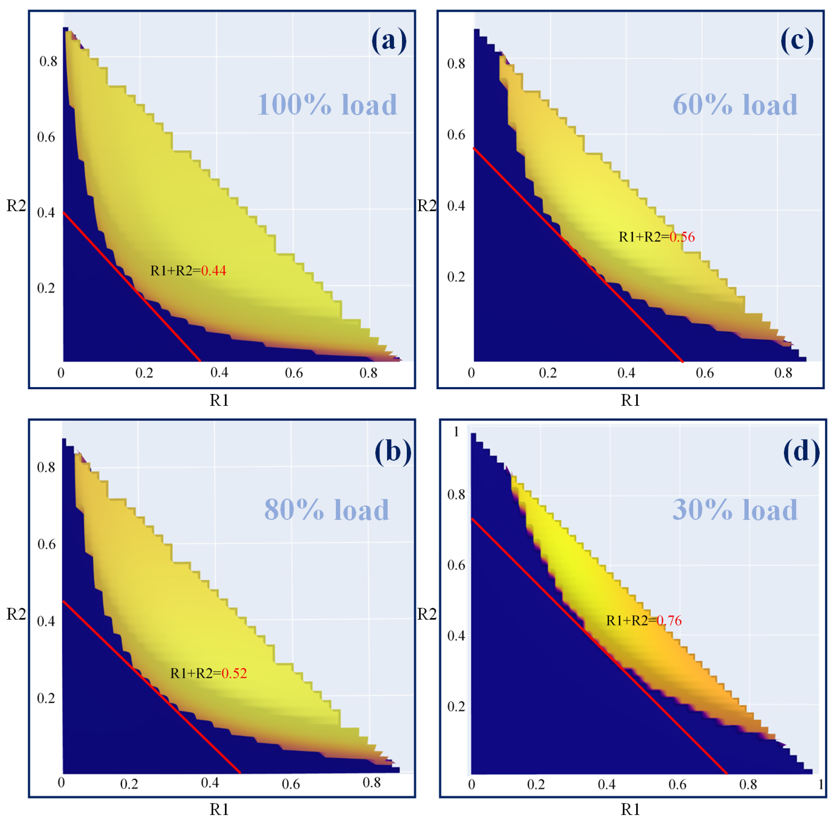
For the auto-thermal ammonia reactor studied in this work, flow split regulation at the inlet is important for temperature control of the catalyst bed. To map the feasible operating region, simulations are carried out using the developed model to study the effect of the inlet flow split ratio on the conversion rate. Figure 6 illustrates the feasible operation region for the inlet flow split under different production loads. As the production load of the reactor decreases, the feasible region for the inlet stream split ratio narrows correspondingly. The contraction of the feasible region, as illustrated in Figure 6, means that a larger proportion of the inlet stream must be directed through the intercoolers for preheating. This adjustment is required to compensate for heat losses from load reduction and ensure the catalyst bed remains above its activation temperature. The results further indicate that maintaining the quench flow splitting ratio within the feasible region is essential during load regulation. Deviation from this region may cause reactor extinction, whereas variations within the region do not significantly affect the conversion rate. Based on the analysis, we can also further confirm that fixing the splitting ratios of the two quench flows at κ 1 = 0.4 and κ 2 = 0.5 rational across the load variation range (30–100%) investigated in this study.
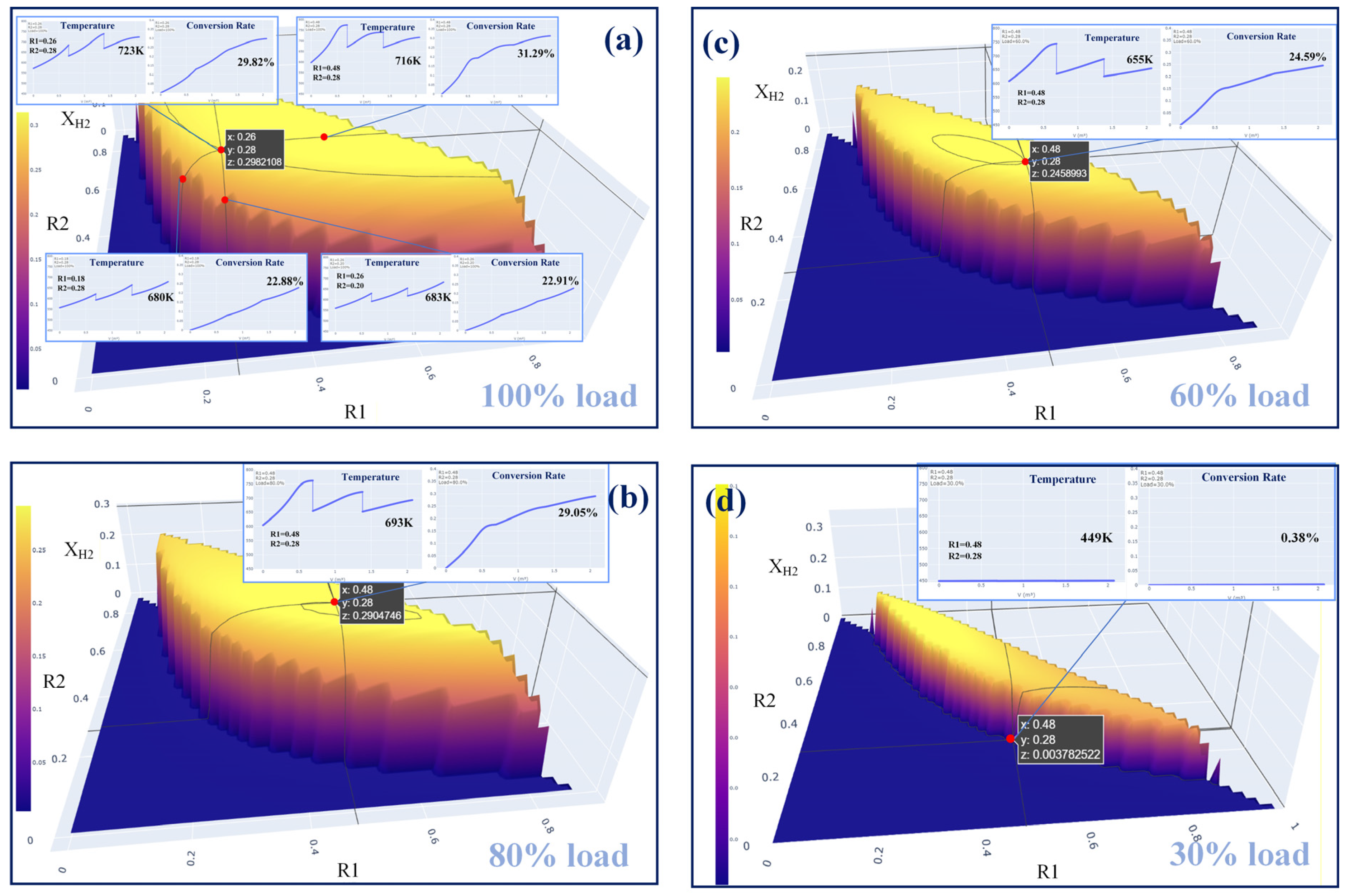
The impact of the inlet flow splitting scheme on the outlet temperature and hydrogen conversion profile of the reactor is illustrated in Figure 7 under various production loads. As shown, different inlet stream splitting schemes lead to distinct temperature profiles within the catalyst beds, resulting in varied reaction conversion rates. Suboptimal raw material flow to the interstage heat exchange leads to low inlet temperatures, which hinders reaction completion throughout the catalyst beds. As shown in Figure 7a, directing 18% and 28% of the inlet flow to the first and second interstage heat exchangers, respectively, resulted in moderate temperature rises across each catalyst bed and a relatively low overall conversion rate (22.88%). Increase the proportion for the first interstage heat exchange, it can be observed that the temperature rises across each catalyst bed become steeper and the temperature in some catalyst beds eventually plateaued. For example, when 48% and 28% of the inlet flow were directed to the first and second inter-stage heat exchangers, respectively, the temperatures in all three catalyst beds reached a plateau. This indicated that the catalytic beds were being efficiently utilized for product conversion. Under this condition, an overall conversion rate of 31.29% can be achieved. With the production load decreasing at a fixed splitting ratio, the overall conversion rate declines as a result of reduced reaction heat release. This finding underscores the necessity of selecting an appropriate feed splitting ratio during operation. This is crucial to accommodate the wide-range load fluctuations inherent in green ammonia production and to prevent the operating point from entering an infeasible region, which could lead to reactor quenching.

4.2. Optimization of the Reactor Inlet Pressure and Ammonia Separation Temperature Under Load Fluctuations

In this section, we examine the influence of reactor inlet pressure variations on the steady-state operating trends of key process variables, as well as on the optimization of the ammonia production under different operating conditions.
As previously noted, the inlet gas compression and ammonia separation units represent the most energy-intensive stages in the ammonia synthesis process. The energy consumption of these systems is inherently tied to reactor performance. Higher compression energy elevates reactor pressure, thereby improving the single-pass conversion rate. Similarly, increased energy input into ammonia refrigeration enhances separation efficiency, which in turn affects the production rate and can lead to the accumulation of inert gases within the system. Thus, the operation of these two units largely governs the unit production cost. Simulations were performed using the aforementioned equations to identify the optimal operating parameters for both the inlet gas compression and the ammonia refrigeration unit under varying production loads.
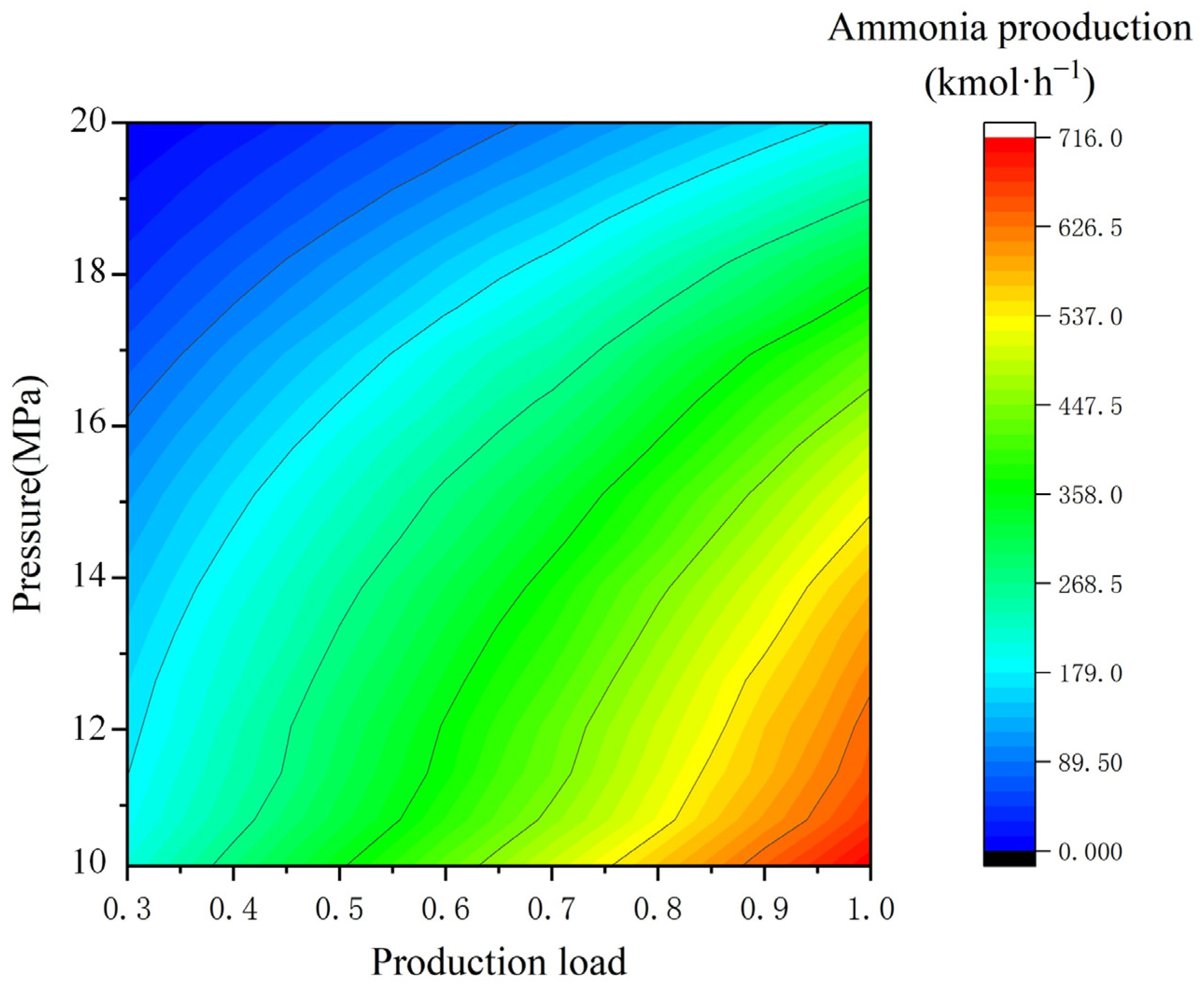
As shown in Figure 8, ammonia production exhibits a clear regional distribution pattern with changes in production load and pressure. As the production load increases from 30% to 100%, ammonia production generally increases. Meanwhile, under the same production load, a higher operating pressure corresponds to a higher ammonia production rate, because high pressure is favorable for improving the equilibrium conversion of ammonia synthesis and enhancing the driving force toward ammonia formation. The high ammonia production region is mainly concentrated under high-load and high-pressure conditions, whereas the low-load and low-pressure region corresponds to relatively low ammonia production.
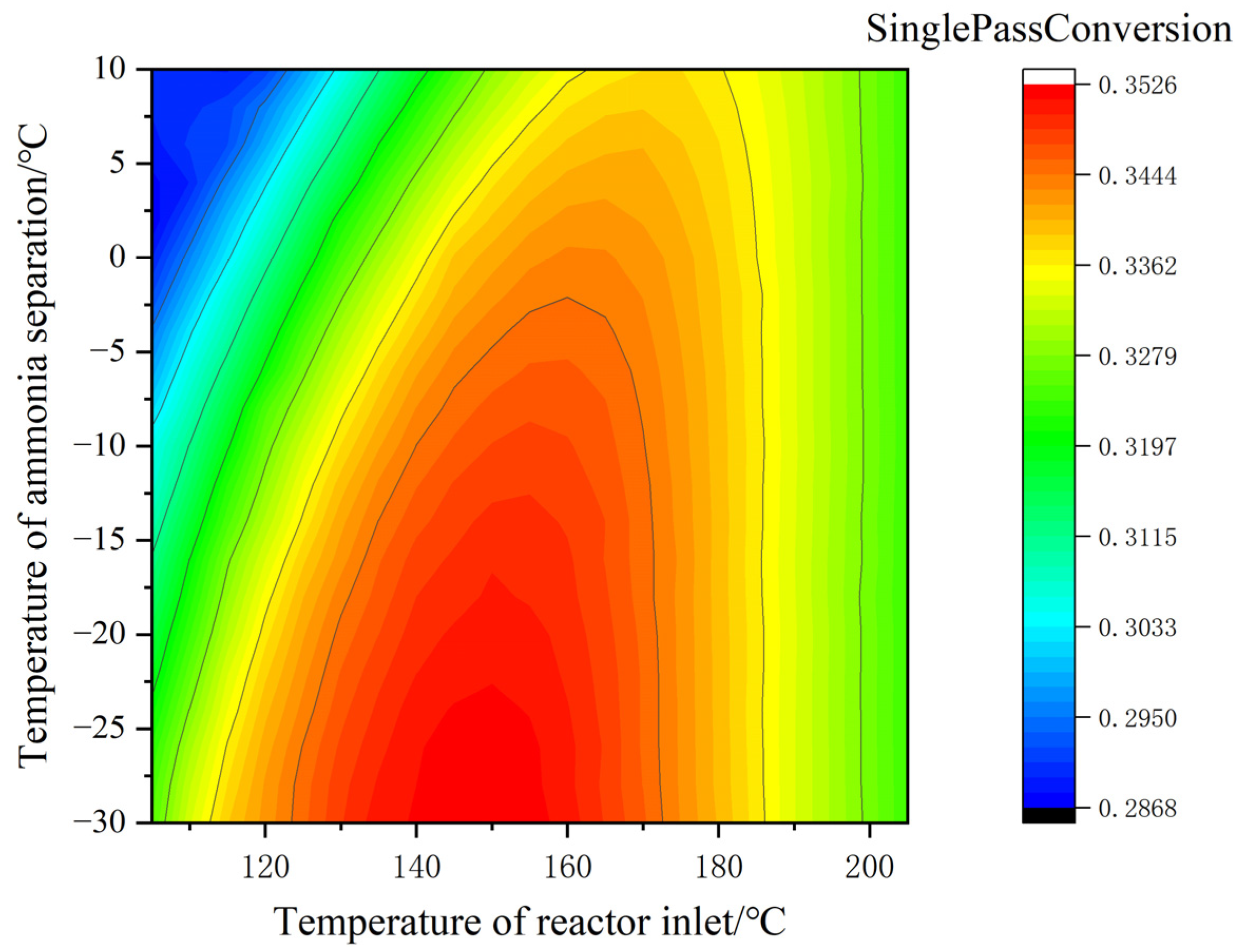
As shown in Figure 9, the single-pass conversion is affected by both the reactor temperature and the flash temperature. With increasing reactor temperature, the single-pass conversion first increases and then decreases, indicating the trade-off between reaction kinetics and thermodynamic equilibrium in ammonia synthesis. A relatively high conversion region appears at moderate reactor temperatures, while excessively high reactor temperatures reduce the equilibrium conversion. In addition, a lower flash temperature is favorable for improving the single-pass conversion, since more ammonia can be separated from the recycle gas, thereby enhancing the driving force for ammonia formation. Therefore, suitable coordination between reactor temperature and flash temperature is important for improving the conversion performance of the synthesis loop.
Table 2 gives the optimized operating parameters for the ammonia synthesis loop and the corresponding ammonia yield under different production loads. It can be observed that, when ammonia production is selected as the objective function, the optimal operating conditions exhibit distinct variation trends as the production load decreases. Specifically, it is recommended to decrease the reactor inlet temperature when the production load is reduced from 100% to 70%, and then it is recommended to increase the inlet temperature when the production load is decreased from 70 to 30. For the ammonia separation temperature, a relatively low value is recommended to maintain a high separation efficiency and a low inlet NH3 concentration at the reactor inlet. The operating pressure is initially recommended to be maintained near the upper bound at high loads and then gradually decreases toward the lower bound as the load is reduced. This recommendations reflects the trade-off among reaction thermodynamics, reaction kinetics, and separation performance. At high production loads, a relatively high pressure is favorable for increasing the driving force of ammonia synthesis and achieving a higher ammonia production rate. However, when the reactor pressure approaches the upper pressure constraint, further increasing the feed load mainly requires a higher purge flow to maintain the steady-state loop pressure and material balance, rather than proportionally increasing ammonia yield. Meanwhile, the reactor inlet temperature remains at a moderate level to the balance reaction rate and thermodynamic equilibrium. As the load decreases, the reduced feed flow rate lowers the demand for a high reaction rate, and a lower reactor inlet temperature becomes favorable for shifting the equilibrium of the exothermic ammonia synthesis reaction toward ammonia formation. However, when further reducing the production load, the decrease in operating pressure weakens the reaction driving force, and the limitation of reaction kinetics at low temperature becomes more significant. Therefore, the optimal reactor inlet temperature increases again to compensate for the unfavorable effects of low pressure and low load on the reaction rate. In addition, the flash temperature remains near its lower bound, indicating that a lower flash temperature is beneficial for enhancing ammonia condensation and separation, thereby reducing the ammonia content in the recycle gas and promoting continuous ammonia formation. Overall, the recommended operating parameters necessitate a balanced coordination among reaction thermodynamics, kinetics, and separation performance to maximize ammonia production under variable load conditions.

5. Conclusions and Outlook

The intermittency and variability of renewable energy generation lead to an unstable supply of green hydrogen, making flexible green ammonia production essential. This study proposes a simulation and optimization methodology for ammonia reactor operation under varying loads. The proposed method was applied to a case study where a three-bed quench cooled adiabatic reactor is used for ammonia synthesis. The results indicate that the proposed method effectively identifies the feasible operating region of the ammonia synthesis reactor under different loads. The proposed method is also used to optimize the operating parameters of the ammonia synthesis loop over a wide operating window from 30% to 100% of nominal capacity. The results demonstrate that the proposed method can effectively optimize operating parameters under various production loads. While steady-state modeling is adopted in this work to capture the fundamental thermodynamic, kinetic, and separation performance trade-offs under different load setpoints, it is important to acknowledge its limitations for dynamic flexible operation. The steady-state approach assumes instantaneous transitions between load conditions and neglects transient phenomena such as thermal inertia, pressure propagation delays, and control system response times. Under practical fluctuating operating conditions, these transient effects may cause temporary deviations from the predicted optimal parameters, potentially leading to suboptimal performance or even violations of operational constraints. Nevertheless, the steady-state framework provides a computationally efficient basis for identifying optimal operating windows across the load range, which can subsequently guide dynamic modeling efforts or be integrated with feedback control strategies to handle real-time fluctuations. Future work will extend this framework to dynamic simulations to explicitly account for transient behaviors. Furthermore, it should be noted that system configurations can significantly influence reactor stability, conversion behavior, and optimization outcome. While applying the proposed method to a different plant configuration, different quantitative results may be derived. In this study, ammonia production was prioritized as the optimization objective to focus on identifying the feasible operating region and production capability of the synthesis loop under varying loads. This simplified objective function effectively highlights the impact of key operating variables on ammonia yield and feasibility. While integrating energy and economic metrics would offer a more holistic evaluation, this is deferred to future work. Future work will extend the present yield-oriented optimization framework to a more comprehensive multi-objective optimization framework by incorporating energy consumption, operating cost, levelized cost of ammonia (LCOA), and profit, so as to further evaluate the economic feasibility and practical performance of flexible green ammonia production.

Supplementary Materials

The following supporting information can be downloaded at: https://www.mdpi.com/article/10.3390/pr14132055/s1, Table S1. Input data for the electrolysis system; Table S2. Cost parameters for renewable power generation equipment; Table S3. Equipment purchase cost data used with Equation (S3), referring to the year 2001; Table S4. The bare module factors for different equipment to be used in Equation (S4); Table S5. Assumptions for estimating operating costs; Table S6. Representative physical properties of the main process streams under dominant operating conditions; Table S7. Main operating ranges and equipment specifications of the case study; Table S8. Variation domain of the input variables for the catalyst bed; Table S9. Variation domain of the input variables for the separator unit; Table S10. Validation results of the catalyst bed model; Table S11. Validation results of the separation unit; Figure S1. Residual plot of the surrogate model of the catalyst bed; Figure S2. Residual plot of the surrogate model of the separator unit [44,45,46,47,48,49,50].

Author Contributions

Conceptualization, L.Z. and X.J.; methodology, L.Z.; software, P.N.; validation, P.N., X.Z. and Y.W.; formal analysis, P.N. and X.Z.; investigation, P.N. and X.Z.; resources, L.Z.; data curation, L.Z.; writing—original draft preparation, P.N.; writing—review and editing, L.Z.; visualization, X.Z. and Y.W.; supervision, L.Z.; project administration, X.J.; funding acquisition, X.J. All authors have read and agreed to the published version of the manuscript.

Funding

This research was funded by the National Natural Science Foundation of China (Grant No. 22478260 and 22108178). The APC was funded by the Project of National Key Research and Development Program of China (Grant No. 2021YFB4000502).

Data Availability Statement

The original contributions presented in this study are included in the article/Supplementary Materials. Further inquiries can be directed to the corresponding author.

Conflicts of Interest

Author Yi Wang is employed by China Petroleum Engineering & Construction Co., Ltd. The remaining authors declare that the research was conducted in the absence of any commercial or financial relationships that could be construed as a potential conflict of interest.

Abbreviations

Notation κFlow splitting ratio at the reactor inlet
Sets
CPSet of compressorsνStoichiometric coefficient
Symbols Subscripts
AHeat transfer areabSet of reactor beds
AcellActive electrode area, m2cpCompressor
C The ratio of specific heat capacityiComponent index
CpSpecific heat at constant pressure, J·kg−1·K−1kSplit stream at the reactor inlet
FFlow rate of a stream, kmol·h−1n, n′Index of HDMR input variables
RReactor outlet stream
FaraFaraday constant, C·mol−1RHXThe heat exchanger after corresponding catalyst beds
f11, f12,
f21, f22
Empirical parameters for alkaline water electrolysis
g0, gn, gnnPolynomial coefficients for the hydrogen conversion surrogate modelspFlash separator
h0, hn, hnnPolynomial coefficients for the outlet temperature surrogate modelSuperscripts
coldCold flow of heat exchanger
iCurrent density, A·m−2hotHot flow of heat exchanger
inInlet stream
K The equilibrium constantliqLiquid outlet stream from the flash separator
LProduction load
LCOAThe levelized cost of ammonia, $·t−1outOutlet stream
mMass flow rate, kg·h−1recycleRecycle gas stream
MWMolar mass, g·mol−1RinReactor inlet stream
NTUNumber of transfer unitvapVapor outlet stream from the flash separator
PPressure, bar
POWPower consumption of a compressor, kW
QcpHeat duty, kW
rH2/N2 molar ratio
R N H 3 The reaction rate
TTemperature, K
UHeat transfer coefficient, W·m−2·K−1
VCatalyst bed volume, m3
XFractional conversion of the corresponding reactant
ZNumber of electrons transferred per ion
εHeat exchanger effectiveness
γPolytropic constant
ηEfficiency

References

  1. Li, Y.; Alharthi, M.; Ahmad, I.; Hanif, I.; Hassan, M.U. Nexus between Renewable Energy, Natural Resources and Carbon Emissions under the Shadow of Transboundary Trade Relationship from South East Asian Economies. Energy Strategy Rev. 2022, 41, 100855. [Google Scholar] [CrossRef]
  2. Rissman, J.; Bataille, C.; Masanet, E.; Aden, N.; Morrow, W.R.; Zhou, N.; Elliott, N.; Dell, R.; Heeren, N.; Huckestein, B.; et al. Technologies and Policies to Decarbonize Global Industry: Review and Assessment of Mitigation Drivers through 2070. Appl. Energy 2020, 266, 114848. [Google Scholar] [CrossRef]
  3. Olabi, A.G.; Abdelkareem, M.A. Renewable Energy and Climate Change. Renew. Sustain. Energy Rev. 2022, 158, 112111. [Google Scholar] [CrossRef]
  4. Olabi, A.G.; Abdelkareem, M.A.; Al-Murisi, M.; Shehata, N.; Alami, A.H.; Radwan, A.; Wilberforce, T.; Chae, K.-J.; Sayed, E.T. Recent Progress in Green Ammonia: Production, Applications, Assessment; Barriers, and Its Role in Achieving the Sustainable Development Goals. Energy Convers. Manag. 2023, 277, 116594. [Google Scholar] [CrossRef]
  5. Rouwenhorst, K.H.R.; Van der Ham, A.G.J.; Mul, G.; Kersten, S.R.A. Islanded Ammonia Power Systems: Technology Review & Conceptual Process Design. Renew. Sustain. Energy Rev. 2019, 114, 109339. [Google Scholar] [CrossRef]
  6. Mehrpooya, M.; Pakzad, P. Introducing a Hybrid Mechanical—Chemical Energy Storage System: Process Development and Energy/Exergy Analysis. Energy Convers. Manag. 2020, 211, 112784. [Google Scholar] [CrossRef]
  7. Liu, T.; Liu, D.; Zhang, X.; Xiong, M.; Ji, X.; Zhou, L. Stochastic Planning Optimisation Design of Power-to-Ammonia Synthesis Reactor with Inlet Flow Rate Fluctuations. Adv. Eng. Sci. 2025, 57, 101–113. [Google Scholar] [CrossRef]
  8. Hasan, M.H.; Mahlia, T.M.I.; Mofijur, M.; Rizwanul Fattah, I.M.; Handayani, F.; Ong, H.C.; Silitonga, A.S. A Comprehensive Review on the Recent Development of Ammonia as a Renewable Energy Carrier. Energies 2021, 14, 3732. [Google Scholar] [CrossRef]
  9. Chehade, G.; Dincer, I. Progress in Green Ammonia Production as Potential Carbon-Free Fuel. Fuel 2021, 299, 120845. [Google Scholar] [CrossRef]
  10. Menefee, A.H.; Schwartz, B.A. Comparing Green Hydrogen and Green Ammonia as Energy Carriers in Utility-Scale Transport and Subsurface Storage. Energy Clim. Change 2024, 5, 100163. [Google Scholar] [CrossRef]
  11. Erdemir, D.; Dincer, I. A Quicker Route to Hydrogen Economy with Ammonia. Int. J. Hydrogen Energy 2024, 82, 1230–1237. [Google Scholar] [CrossRef]
  12. Cao, C.; Wen, B.; Fang, Y.; Hou, Z.; Wang, Q.; Zhang, T.; Huang, L.; Chen, Q.; Zhang, L.; Zhao, Y.; et al. A Comprehensive Comparison of Green Ammonia and Green Methanol from a Full Chain: Production, Transportation, Storage and Utilization. Carbon Neutr. Syst. 2025, 1, 8. [Google Scholar] [CrossRef]
  13. Michalsky, R.; Avram, A.M.; Peterson, B.A.; Pfromm, P.H.; Peterson, A.A. Chemical Looping of Metal Nitride Catalysts: Low-Pressure Ammonia Synthesis for Energy Storage. Chem. Sci. 2015, 6, 3965–3974. [Google Scholar] [CrossRef] [PubMed]
  14. Ithisuphalap, K.; Zhang, H.; Guo, L.; Yang, Q.; Yang, H.; Wu, G. Photocatalysis and Photoelectrocatalysis Methods of Nitrogen Reduction for Sustainable Ammonia Synthesis. Small Methods 2019, 3, 1800352. [Google Scholar] [CrossRef]
  15. Wu, T.; Fan, W.; Zhang, Y.; Zhang, F. Electrochemical Synthesis of Ammonia: Progress and Challenges. Mater. Today Phys. 2021, 16, 100310. [Google Scholar] [CrossRef]
  16. Wang, Q.; Guo, J.; Chen, P. Recent Progress towards Mild-Condition Ammonia Synthesis. J. Energy Chem. 2019, 36, 25–36. [Google Scholar] [CrossRef]
  17. Reese, M.; Marquart, C.; Malmali, M.; Wagner, K.; Buchanan, E.; McCormick, A.; Cussler, E.L. Performance of a Small-Scale Haber Process. Ind. Eng. Chem. Res. 2016, 55, 3742–3750. [Google Scholar] [CrossRef]
  18. Gorre, J.; Ortloff, F.; van Leeuwen, C. Production Costs for Synthetic Methane in 2030 and 2050 of an Optimized Power-to-Gas Plant with Intermediate Hydrogen Storage. Appl. Energy 2019, 253, 113594. [Google Scholar] [CrossRef]
  19. Ikäheimo, J.; Kiviluoma, J.; Weiss, R.; Holttinen, H. Power-to-Ammonia in Future North European 100% Renewable Power and Heat System. Int. J. Hydrogen Energy 2018, 43, 17295–17308. [Google Scholar] [CrossRef]
  20. Ostuni, R.; Zardi, F. Method for Load Regulation of an Ammonia Plant. U.S. Patent US9463983B2, 11 October 2016. [Google Scholar]
  21. Morud, J.C.; Skogestad, S. Analysis of Instability in an Industrial Ammonia Reactor. AIChE J. 1998, 44, 888–895. [Google Scholar] [CrossRef]
  22. Stephens, A.D.; Richards, R.J. Steady State and Dynamic Analysis of an Ammonia Synthesis Plant. Automatica 1973, 9, 65–78. [Google Scholar] [CrossRef]
  23. Cheema, I.I.; Krewer, U. Optimisation of the Autothermal NH3 Production Process for Power-to-Ammonia. Processes 2020, 8, 38. [Google Scholar] [CrossRef]
  24. Cheema, I.I.; Krewer, U. Operating Envelope of Haber–Bosch Process Design for Power-to-Ammonia. RSC Adv. 2018, 8, 34926–34936. [Google Scholar] [CrossRef] [PubMed]
  25. Fahr, S.; Schiedeck, M.; Schwarzhuber, J.; Rehfeldt, S.; Peschel, A.; Klein, H. Design and Thermodynamic Analysis of a Large-Scale Ammonia Reactor for Increased Load Flexibility. Chem. Eng. J. 2023, 471, 144612. [Google Scholar] [CrossRef]
  26. Verleysen, K.; Parente, A.; Contino, F. How Sensitive Is a Dynamic Ammonia Synthesis Process? Global Sensitivity Analysis of a Dynamic Haber-Bosch Process (for Flexible Seasonal Energy Storage). Energy 2021, 232, 121016. [Google Scholar] [CrossRef]
  27. Rosbo, J.W.; Ritschel, T.K.S.; Hørsholt, S.; Huusom, J.K.; Jørgensen, J.B. Flexible Operation, Optimisation and Stabilising Control of a Quench Cooled Ammonia Reactor for Power-to-Ammonia. Comput. Chem. Eng. 2023, 176, 108316. [Google Scholar] [CrossRef]
  28. Speth, C.H.; Hultqvist, M.; Han, P.A. Method for the Control of Pressure in a Loop for the Preparation of Ammonia or Methanol. U.S. Patent US2023202853A1, 29 June 2023. [Google Scholar]
  29. Rizzi, M. Control of an Ammonia Synthesis Loop at Partial Load. European Patent EP4237375A1, 9 June 2023. [Google Scholar]
  30. Kolbe, B.; Roosen, C.; Johanning, J.; Schulte Beerbühl, S.; Schultmann, F. Verfahren Sowie Anlage Zur Herstellung Eines Produktgases Unter Wechselnden Lastbedingungen. European Patent EP3426601B1, 6 May 2020. Available online: https://patents.google.com/patent/EP3426601B1/en (accessed on 10 April 2026).
  31. Bazmi, M.; Tabarkhoon, F.; Nomura, K.; Jessen, K.; Tsotsis, T.T. An AI Framework for Optimization of Operating Conditions, Geometry, and Material Screening in Membrane Gas Separation. Sep. Purif. Technol. 2026, 380, 135306. [Google Scholar] [CrossRef]
  32. Al Masud, M.A.; Schreiber, K.; Wang, Y.; Hu, J.; Tian, Y. Surrogate-Based Superstructure Optimization for Techno-Economic and Sustainability Analysis of Microwave-Assisted Ammonia Production Process. Chem. Eng. Process.-Process Intensif. 2026, 219, 110648. [Google Scholar] [CrossRef]
  33. Liu, D.; Wang, Y.; Xiong, M.; Wang, Z.; Zhou, L.; He, G.; Ji, X. Capacity Configuration and Operation Scheduling for Green Ammonia Production. Ind. Eng. Chem. Res. 2025, 64, 13289–13306. [Google Scholar] [CrossRef]
  34. Wang, S.; Xue, X.; Cheng, M.; Chen, S.; Liu, C.; Zhou, L.; Bi, K.; Ji, X. High-throughput computational screening of metal-organic frameworks for CH4/H2 separation by synergizing machine learning and molecular simulation. Acta Chim. Sin. 2022, 80, 614. [Google Scholar] [CrossRef]
  35. Yang, R.; Yue, Z.; Zhang, S.; Lv, Z.; Yao, M. Ammonia Thermal Atmosphere Compression Ignition Combustion Mode to Achieve Efficient Combustion and Low Greenhouse Gas Emissions. Energy Convers. Manag. 2025, 325, 119427. [Google Scholar] [CrossRef]
  36. Zhou, J.; Duan, F. Combustion and Emission Characteristics of Industrial Gas Turbine Combustor Fueled with Partially Cracked Ammonia: Effects of Fuel–Air Staging and Mixing. J. Clean. Prod. 2025, 521, 146205. [Google Scholar] [CrossRef]
  37. Sánchez, M.; Amores, E.; Abad, D.; Rodríguez, L.; Clemente-Jul, C. Aspen plus Model of an Alkaline Electrolysis System for Hydrogen Production. Int. J. Hydrogen Energy 2020, 45, 3916–3929. [Google Scholar] [CrossRef]
  38. China Huanqiu Chemical Engineering Corporation. Nitrogen Fertilizer Process Design Manual: Gas Compression, Ammonia Synthesis, Methanol Synthesis [氮肥工艺设计手册:气体压缩、氨合成、甲醇合成]; Chemical Industry Press: Beijing, China, 1989; Available online: https://pdfyl.ertongbook.com/32/31579719.pdf (accessed on 10 April 2026). (In Chinese)
  39. Khademi, M.H.; Sabbaghi, R.S. Comparison between Three Types of Ammonia Synthesis Reactor Configurations in Terms of Cooling Methods. Chem. Eng. Res. Des. 2017, 128, 306–317. [Google Scholar] [CrossRef]
  40. Li, X.; Feng, W.; Tian, C.; Yang, X. Problems occurred on KBR horizontal synthetic tower and its improvement. Large Scale Nitrogenous Fertil. Ind. 2022, 45, 162–165. [Google Scholar] [CrossRef]
  41. Wang, S.; Zhou, L.; Ji, X.; Karimi, I.A.; He, G.; Dang, Y.; Xu, X. A Surrogate-Assisted Approach for the Optimal Synthesis of Refinery Hydrogen Networks. Ind. Eng. Chem. Res. 2019, 58, 16798–16812. [Google Scholar] [CrossRef]
  42. Xiong, M.; Liu, D.; Wang, Z.; Zhou, L.; Ji, X. Optimization and adjustment of operating parameters for green ammonia production under variable load conditions. CIESC J. 2025, 76, 2791. [Google Scholar] [CrossRef]
  43. Rovaglio, M.; Manca, D.; Cortese, F. A Reliable Control for the Ammonia Loop Facing Limit-cycle and Snowball Effects. AIChE J. 2004, 50, 1229–1241. [Google Scholar] [CrossRef]
  44. Qi, M.; Kim, M.; Dat Vo, N.; Yin, L.; Liu, Y.; Park, J.; Moon, I. Proposal and Surrogate-Based Cost-Optimal Design of an Innovative Green Ammonia and Electricity Co-Production System via Liquid Air Energy Storage. Appl. Energy 2022, 314, 118965. [Google Scholar] [CrossRef]
  45. Lin, B.; Wiesner, T.; Malmali, M. Performance of a Small-Scale Haber Process: A Techno-Economic Analysis. ACS Sustain. Chem. Eng. 2020, 8, 15517–15531. [Google Scholar] [CrossRef]
  46. Turton, R.; Bailie, R.C.; Whiting, W.B.; Shaeiwitz, J.A. Analysis, Synthesis and Design of Chemical Processes; Pearson Education: London, UK, 2008. [Google Scholar]
  47. Quintero-Masselski, C.; Portha, J.-F.; Falk, L. Conception and Optimization of an Ammonia Synthesis Superstructure for Energy Storage. Chem. Eng. Res. Des. 2022, 177, 826–842. [Google Scholar] [CrossRef]
  48. Osman, O.; Sgouridis, S.; Sleptchenko, A. Scaling the Production of Renewable Ammonia: A Techno-Economic Optimization Applied in Regions with High Insolation. J. Clean. Prod. 2020, 271, 121627. [Google Scholar] [CrossRef]
  49. Zhang, H.; Wang, L.; Van Herle, J.; Maréchal, F.; Desideri, U. Techno-Economic Comparison of Green Ammonia Production Processes. Appl. Energy 2020, 259, 114135. [Google Scholar] [CrossRef]
  50. Jin, R.; Chen, W.; Simpson, T.W. Comparative Studies of Metamodelling Techniques under Multiple Modelling Criteria. Struct. Multidiscip. Optim. 2001, 23, 1–13. [Google Scholar] [CrossRef]
Figure 1. Schematic of green ammonia production based on the Haber–Bosch process.
Processes 14 02055 g001
Figure 2. Outline of the targeted green ammonia synthesis loop.
Processes 14 02055 g002
Figure 3. Schematic diagram of an ammonia synthesis reactor and the modeling strategy.
Processes 14 02055 g003
Figure 4. Modeling scheme of the flash separation unit.
Processes 14 02055 g004
Figure 5. Flowchart of the differential evolution-based optimization procedure.
Processes 14 02055 g005
Figure 6. Feasible operation region for the reactor inlet flow split under: (a) 100% production load, (b) 80% production load, (c) 60% production load, and (d) 30% production load.
Processes 14 02055 g006
Figure 7. Effect of the inlet flow splitting scheme on the reactor outlet temperature and hydrogen conversion profile across different production loads: (a) 100% production load, (b) 80% production load, (c) 60% production load, and (d) 30% production load.
Processes 14 02055 g007
Figure 8. Distribution of ammonia production under different production loads and pressures.
Processes 14 02055 g008
Figure 9. Effects of reactor temperature and flash temperature on single-pass conversion.
Processes 14 02055 g009
Table 1. System configuration of the ammonia synthesis system for the case study.
EquipmentSpecificationValueUnit
Muti-stage compressing
(efficiency 90%)
Rated capacity of the 1st stage compressor920.45kW
Rated capacity of the 2nd stage compressor920.45kW
Rated capacity of the 3rd stage compressor920.45kW
Catalyst bedsVolume of the 1st catalyst bed6m3
Volume of the 2nd catalyst bed6m3
Volume of the 3rd catalyst bed6m3
Flash separationVolume of the 1st stage flash separator10m3
Volume of the 2nd stage flash separator10m3
RecycleRated capacity of the recycle compressor61.49kW
Table 2. Optimized operating conditions and ammonia production under different production loads.
Production LoadReactor Inlet Temperature (°C)Stripping Temperature (°C)Reactor Pressure (bar)Ammonia Yield (kmol/h)Relative
Production 1
1142.1−29.9199.88605.271.00
0.9136.0−30.0199.87546.510.90
0.8135.4−24.7199.99494.070.82
0.7124.9−29.4199.94453.300.75
0.6121.9−30.0199.37427.690.71
0.5128.8−27.3180.43356.000.59
0.4152.4−29.6159.97283.860.47
0.3154.0−24.0124.00212.780.35
Note: 1 Relative production, ratio of the actual ammonia yield, and the production capacity.
Disclaimer/Publisher’s Note: The statements, opinions and data contained in all publications are solely those of the individual author(s) and contributor(s) and not of MDPI and/or the editor(s). MDPI and/or the editor(s) disclaim responsibility for any injury to people or property resulting from any ideas, methods, instructions or products referred to in the content.