1. Introduction
Weak soils, which constitute a large part of the study area of geotechnical engineering, are increasing in importance with the increase in construction. Even if it is problematic in terms of bearing capacity or settlement, civil engineering structures must be constructed on such soils by using the necessary reinforcement or improvement methods. Weak soils are those that cannot be transported safely and economically without causing any problems during the service life of the road superstructure and road structures (embankments, excavations, bridges, viaducts, tunnels, etc.). In other terms, weak soils can be defined as clayey, silty, organic matter-containing soils where the underground water level is close to the ground, loose fine sandy alluvial soils, and artificial fillings formed uncontrollably. By the definition of weak soils, necessary improvements should be made in the road embankments to be built on such soils, so that the ground can safely carry the loads on it. At the present time, many methods are used to improve weak soils. Improvements in engineering embankments with geosynthetics and the application of jet injection to strengthen the sub-fill ground are some of these strengthening methods.
The studies aimed at improving the soils under road embankments with the jet injection method and strengthening road fills by using geogrids are summarized. Some of the experimental and numerical studies carried out are summarized below.
Lunardi [
1] stated that the jet injection method is quite economical and effective in soil improvement problems. The results obtained by applying the method are very encouraging and constitute the best incentive for continued research and experimentation. Baumann [
2] studied the changes in uniaxial compressive strength in different types of soils improved with jet columns. According to the results of the research, it was observed that the compressive strength obtained in sandy and gravelly soils is much higher (3–4 times more) compared to clayey soils. Trevi [
3] examined the relationship between the modulus of elasticity and the uniaxial compressive strength of jet grout columns. It was concluded that the jet grout column strength is directly proportional to the modulus of elasticity. Durgunoğlu et al. [
4] improved soil with the jet grout method and explained a case study. It was shown that high-modulus jet columns can limit the lateral spreading and vertical displacements of the soil. Wong and Poh [
5] investigated the use of jet columns to prevent movement in diaphragm walls on their side surfaces during basement excavation in adjacent structures. They showed that jet columns help minimize movements that occur with basement excavation. Uniaxial compression tests were carried out in a laboratory with cores taken from Bell et al. [
6] super jet grout columns. Kirsch and Sondermann [
7] used jet columns to improve the soil at the foundation of a building and demonstrated that the improvement is safe and economical by using different numerical analyses and modeling approaches. Durgunoğlu et al. [
8] studied the improvement of a construction site with the jet injection method. It was observed that the study’s results met the risk of liquefaction and the required displacement rate. Saglamer et al. [
9] performed soil improvement with jet columns to solve the settlement problems of a facility. The application steps of the jet grout method were explained, and the course of the study was discussed in detail. Özsoy and Durgunoğlu [
10] proposed a new calculation method for reducing the effects of liquefaction with jet grout and deep mixing soil improvement techniques. Depending on the shear modulus ratio between the jet grout column and soil, they found that the stress reduction coefficient changes with the area replacement ratio. Bzowka [
11] carried out a numerical analysis of a jet grouting application in his study. The obtained data and empirical solution results were compared. Based on the numerical analysis, it was stated that the loads and settlements on jet grout columns could be calculated. In the study, the problem was modeled in its real dimensions. Tschuchnigg and Schweiger [
12] stated that jet columns can be used as an economical alternative to conventional pile or piled raft foundations. Various studies have been carried out on soils reinforced with geosynthetics. The results obtained from the comparison of different models show that all models give the same order of magnitude for deformations. The total maximum difference in vertical settlements for all the different modeling assumptions is less than 5% and, therefore, insignificant. Binquet and Lee [
13] investigated the bearing capacity of strip foundations resting on reinforced sand ground with model experiments carried out in the laboratory. The results showed that benefits may be obtained in both load settlement and ultimate bearing capacity by the use of a modest amount of reinforcing. Mandal and Sah [
14] investigated the effect of geogrid reinforcements placed horizontally in a clay soil layer on the bearing capacity of a foundation. The introduction of geogrid reinforcement increased the bearing capacity by about 1.36 times. Ramaswamy and Purushothaman [
15] investigated the bearing capacity of foundations resting on clay soil with geogrid reinforcement by conducting experimental studies. They achieved a maximum bearing capacity when the reinforcement was placed at 0.5 times the footing width. Shin et al. [
16] investigated the carrying capacities of strip foundations resting on saturated clayey soil with geogrid reinforcements by laboratory tests. They indicated that the optimal positioning of the top layer for three geogrid layers was around 0.4 times the footing width. Alawaji [
17] investigated the reinforcement of sand soils with geogrid reinforcements. Gabr and Hart [
18] carried out model experiments to calculate the modulus of elasticity for sand soils reinforced with polymer geogrids. DeMerchant [
19] performed plate loading tests on low-density aggregate reinforced with geogrid. The behavior of the geogrid according to the stiffness values was explained. Huang and Tatsuoka [
20] developed an analytical method to calculate the bearing capacity of strip foundations resting on reinforced sandy soils. Otani et al. [
21] analyzed the capacity of flexible uniform strip foundations resting on cohesive soils with geosynthetic reinforcement using a rigid plastic finite element formulation. The effect of a geosynthetic reinforced granular layer placed on soft soil on the bearing capacity was investigated by Jamir and Deb [
22]. Vashi et al. [
23] examined the strengthening ability of road embankments using geotextiles and investigated the relationship between the coefficient of safety of fill slopes and the vertical spacing and slope angle of the geotextile. Cicek et al. [
24] investigated the increase in slope stability of embankments to be built on soft clay and examined the effects of a geosynthetic reinforcement with analyses using the finite element model. Some studies carried out on weak soils in recent years are given in [
25,
26,
27,
28,
29,
30]. Ziccarelli and Rosone [
25] performed numerical work to examine the impact of a weak layer on the stress and strain distribution, failure mechanisms, and overall stability of an embankment. They explained that the security multiplier was widely lowered compared to the same status without a weak layer. Eisa et al. [
26] conducted a study that attempted to enhance the properties and strength of weak, clayey ground for usage as a subgrade for pavement structural parts employing a mix of granular and chemical stabilization for the ground. Rad et al. [
27] carried out a study that examined the influence of geosynthetics in weak grounds through numerical modeling. They indicated that geotextile settlement at shallower depths is suggested for sand ground, where the ground experiences higher tension and pressure. Borges and Marques [
28] presented a study that analyzed the time-dependent behavior of a geosynthetic-reinforced and jet grout column-supported embankment on soft soils. According to the analysis results, the column supporting and geosynthetic reinforcement technique provides a very significant reduction in settlements, both at the base and on the top of the fill. As a result of the analysis, it was stated that the long-term average settlement value decreased from 41 cm to 11.4 cm with the reinforcement of the soil. In the study by Cheng et al. [
29], the authors focused on the behavior of geosynthetic-reinforced and column-supported earth platforms in soft soil. They suggest that the use of a geosynthetic-reinforced and column-supported system can reduce lateral displacements and enhance the stability of an embankment significantly. In the study by Wang et al. [
30], two large-scale field tests of pile-supported embankments with and without reinforcement were carried out to investigate the effect of geosynthetic reinforcement on the improvement of embankments. Test results from the two test sites under similar loading were compared, and it was concluded that the geosynthetic reinforcement considerably influenced the improvement in load transfer and the reduction in total and differential settlements. The geogrid reinforcement also significantly decreased the soil settlements by 55.3–57.6%.
The previous studies mentioned above show that the use of geogrid and jet grout in weak soils can provide an effective improvement in both bearing capacity and settlement values. At the same time, the mentioned methods can also be used to increase the stability of embankment slopes. Small-scale model tests and numerical analysis methods were generally used in the studies. Small-scale models include laboratory studies. While the finite element method is mostly used in numerical studies, finite difference and boundary element methods are also used in other studies. Additionally, there are relatively few field and large-scale studies in the literature. When existing studies in the literature are analyzed, it is seen that optimum parameters are obtained depending on geogrid depths, numbers, and lengths. In studies carried out using jet grout, many parameters, such as column length, spacing, and diameter, are considered, and configurations that provide maximum improvement are investigated. It is seen that the optimum parameters obtained are affected by many parameters, such as model geometry, soil type, and loading condition. Although the results of these studies provide usable values in design and application, studies on the subject are still needed.
The aim of this study is to identify the problems encountered in road embankments built on weak soils, to analyze the problems, and to determine the appropriate improvement methods based on the analysis and put them into practice safely. Within the scope of this study, weak soils were defined, and the bearing capacity of road embankments on weak soils, settlements, etc., and strengthening methods on soils with insufficient bearing capacity and/or settlement problems were examined. In this study, an existing case was discussed, soil properties were determined using in situ and laboratory tests, and bearing capacity, displacement, and stability analyses were carried out using the finite element method. The finite element analyses were carried out using the PLAXIS computer-aided program [
31]. Based on the settlement, the improvement method was judged, and the soil behavior was examined by modeling the post-improvement situation. As a method of improvement, it was decided to strengthen the weak soil by jet grout columns in the ground where the road embankment is constructed and to place geogrids in the road embankment. In the analyses, jet column diameter, length, and spacing were determined, and the optimum geogrid configuration was obtained. Based on the results of the settlements, it was determined that the bearing capacity, settlement, and stability behavior of the soil and road embankment were significantly improved when the selected strengthening methods were applied. Finally, the results of the analysis were examined, and the necessary results and suggestions for the application were presented. Although both geogrid and jet grout techniques have been studied individually, few works have systematically combined them in the context of embankments on weak soils. The novelty of this work lies in the combined evaluation of jet grout columns and geogrid reinforcement using finite element modeling, applied to a real case of an embankment founded on weak soils. Previous studies often considered these techniques separately, whereas here, their integrated effect is systematically analyzed. By addressing this gap, the present research provides novel insights into stability enhancement strategies and contributes to the practical design of road embankments under challenging geotechnical conditions.
2. Materials and Methods
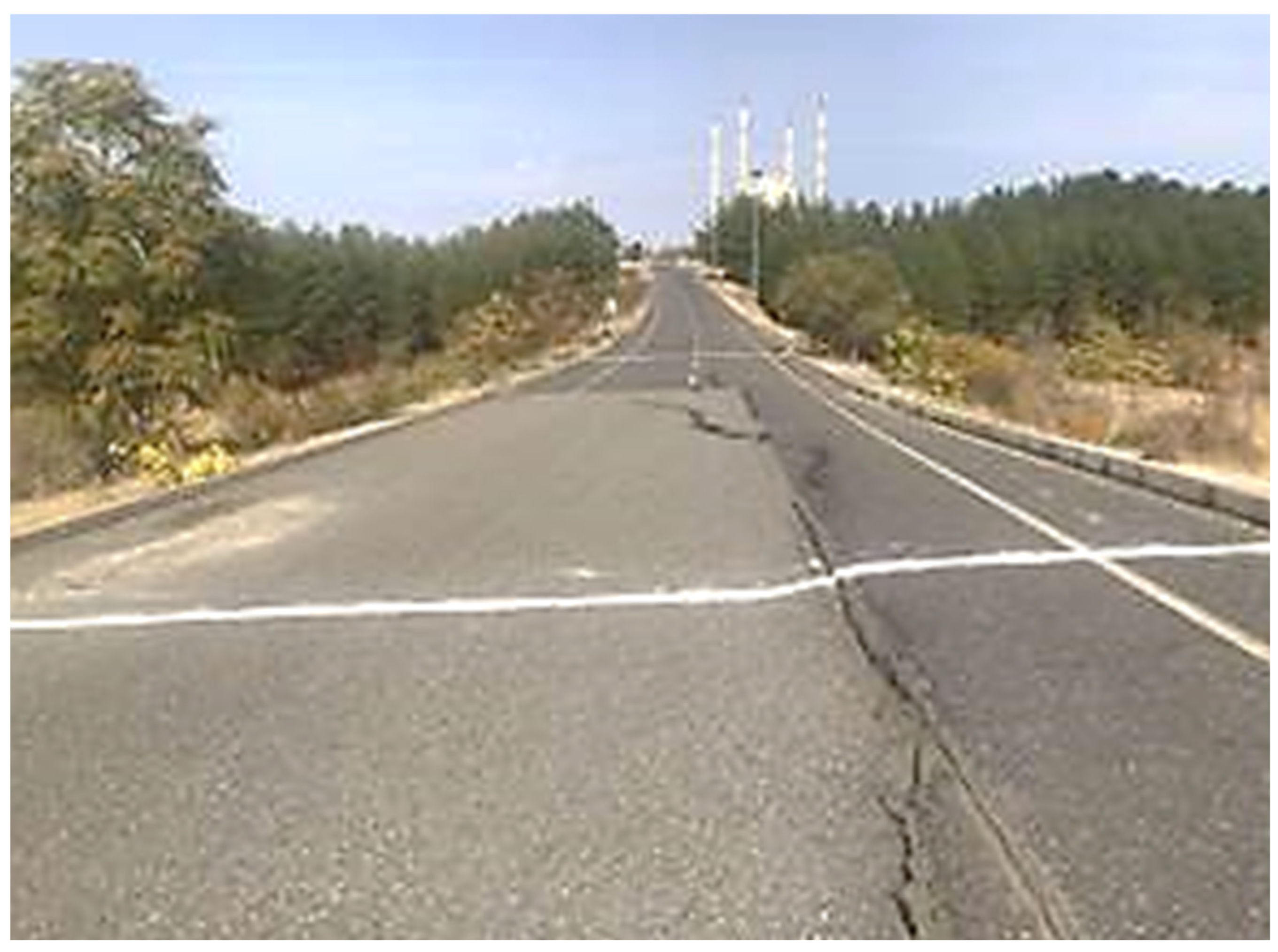
This work aims to investigate the causes of collapses and displacements in a municipal road, to examine it from a geotechnical point of view, and to present solutions. The road is a two-lane, low-technical-class road. For this purpose, first, a field study and laboratory experiments were carried out. In the next step, the problem was modeled with the finite element method, and analyses were performed. The location where this study was carried out is within the Dicle University area in the borders of Diyarbakir Province, Turkey. The location of this study is shown in
Figure 1.
Five boreholes, each with a depth of 20 m, and five test pits, were opened. It was determined that in the boreholes, silty clay with fine gravel from the surface and clayey silty sandy gravel units are encountered with deeper drilling. In the boreholes, it was observed that the road embankment continued up to approximately 17 m. The natural soil under the road embankment consisted of clayey silty sandy gravel units (
Table 1). Geogrid stiffness was obtained from manufacturer data; jet grout stiffness values were adopted from the literature [
11,
28]; Soil parameters were obtained from laboratory and in situ tests.
No groundwater was found in the boreholes. However, it was observed that the soil was quite moist due to surface water and rainfall.
Laboratory experiments were carried out on samples obtained from the boreholes to determine the physical and mechanical properties of the soil. Some of the laboratory test results obtained are shown in
Table 2. It should be noted that the cohesion values in
Table 1 correspond to natural soil test results.
The material used in embankment is considered silty clayey gravel. It is not known whether the embankment was constructed in accordance with engineering rules (optimal water content, whether sufficient density was achieved by laying in layers). It is considered that the technical conditions were partially complied with during its construction.
The height of the road embankment is variable, and the collapsed parts of the embankment correspond to the middle region where the embankment height is highest (
Figure 2).
The calculations indicate that the pressure applied by the embankment load to the foundation soil is approximately 20 t/m2, and the stress value that the foundation soil can carry is 13.1 t/m2. In this case, it is considered that the foundation soil cannot bear the stresses caused by the embankment load.
Since the constructed road embankment is in a valley transition area, it is exposed to water currents. There is a reinforced concrete box culvert at the bottom of the embankment for the discharge of these waters. However, upon examination on site, it was determined that the reinforced concrete box culvert was damaged and did not function effectively.
As a result of the calculations and evaluations, it was determined that the weight of the road embankment could not be supported by the foundation soil and that there was a bearing capacity problem in the embankment base. It was also determined that the embankment was not constructed in accordance with engineering techniques. Due to these reasons, surface and rain water could not be drained in the valley where the fill was located, the reinforced concrete box culvert was damaged and did not work effectively, and collapses occurred in the road embankment. The embankment and foundation soil with insufficient bearing capacity should be improved. Since the reinforced concrete box culvert is damaged, the embankment on the foundation soil must be completely removed in order to be rebuilt. After the embankment is removed, planned improvements in the foundation soil along the road route will be performed with the jet grout method. Thus, the bearing capacity and settlement properties of the foundation soil will be improved, and it will be able to carry the loads coming from the road embankment safely. After the jet grout application, the reinforced concrete box culvert construction will be carried out. The planned embankment will be designed as an engineering filling. The filling material suitable for compaction will be selected, and the embankment will be constructed using geogrid layers.
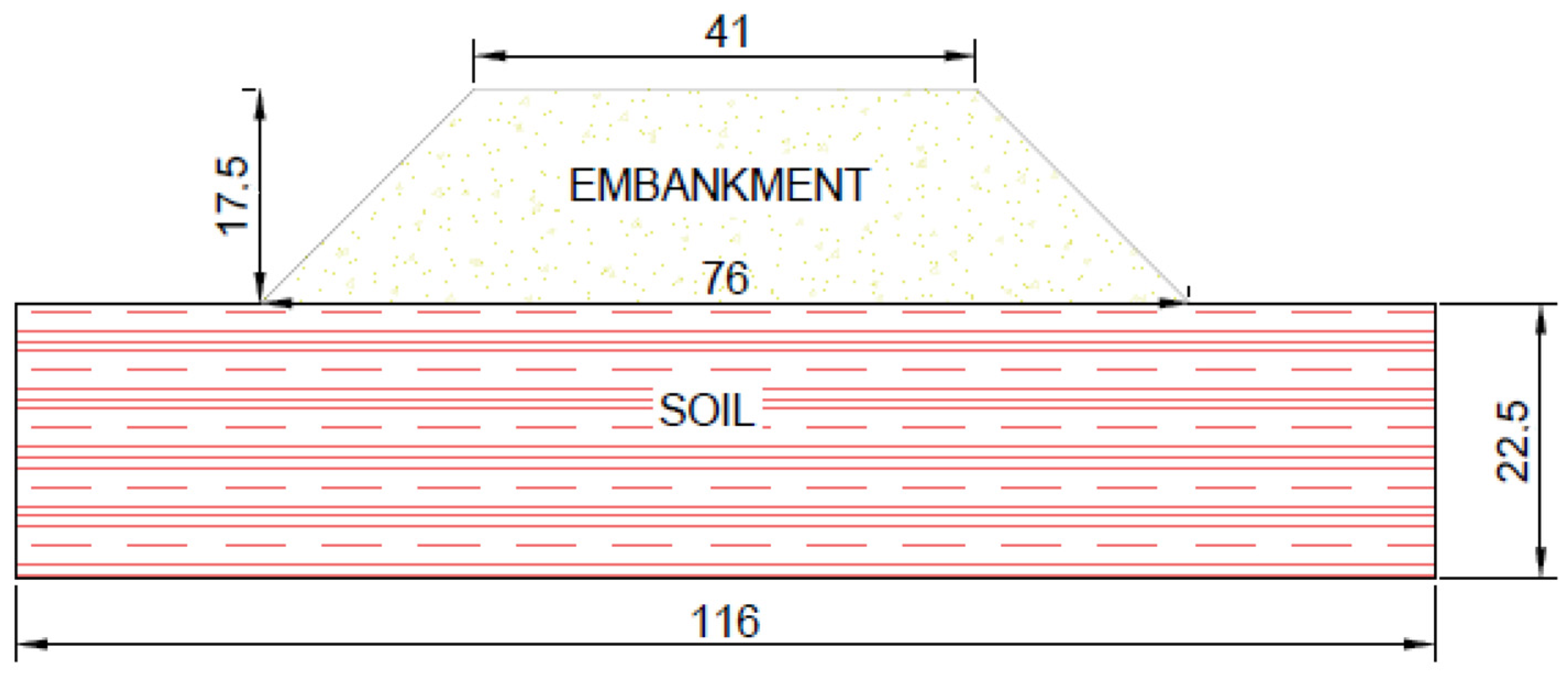
For the stability analyses of the embankment and foundation soil, a model with a width of 116 m and a height of 40 m was formed (
Figure 3). Slope stability and bearing capacity analyses of the model were conducted with PLAXIS, employing the finite element method (FEM). The unreinforced and reinforced settlement results acquired were compared.
The PLAXIS (Finite Element for Soil and Rock Analysis) computer-aided program was designed at Delft Technical University of the Netherlands to analyze river embankments on soft soil using the finite element method (FEM). Although the PLAXIS program was designed to solve many problems in soil and geotechnical engineering, it can also solve problems in different fields. It was designed in a way that even engineers who are not experts in the finite element method can easily use it. Within the scope of this study, PLAXIS version 8.6, which was designed for two-dimensional problems (2D), was used. The geogrid layers were modeled in PLAXIS as geogrid elements with an axial stiffness of EA = 150 kN/m, consistent with typical polymer geogrid products. Jet grout columns were modeled as elastic elements with a flexural rigidity EI = 765 kNm
2/m and axial stiffness EA = 25,500 kN/m. These values were adopted from the literature [
11,
28] where typical stiffness ranges for jet grout were reported. The inclusion of these elements enabled the representation of the reinforcement contribution to slope stability.
PLAXIS can be used to solve many soil problems encountered in geotechnical engineering, such as soil–structure interactions, modeling of the non-linear behavior of soil, modeling of time-dependent soil and rock behavior, and the soil–water relationship (flow analysis), and it provides practical and realistic results. It also allows for expressing the non-linear and elasto-plastic behavior of soil with different material models. In this way, it makes it possible to model soil behavior with a realistic approach. Two-dimensional graphical modeling is performed with PLAXIS. Soil layers, construction structures, construction stages, and loads are defined, and boundary conditions for soil layers are entered into the program.
In the analysis, soil was modeled by the Mohr–Coulomb Model (MCM). In the PLAXIS program, elasto-plastic behavior can be analyzed with the Mohr–Coulomb material model. Elasticity modulus (E), friction angle (ϕ), Poisson ratio (ν), dilatation angle (ψ), and cohesion (c) values are required as input parameters in the model. The input parameters were acquired from laboratory and in situ works, as listed in
Table 3. The Mohr–Coulomb model was selected because the site soils cannot be classified as purely clay or sand. This simplified model provides a conservative design approach by representing shear failure through c–ϕ reduction, ensuring the safety of embankment stability analyses. The model was discretized with 15-node triangular elements in plane strain conditions. Mesh refinement was applied in critical zones around the jet grout columns and the embankment toe. Standard PLAXIS boundary conditions were adopted: u
x = 0 and u
y = 0 at the base, and u
x = 0 and u
y = free along the vertical sides. The jet grout columns were modeled as elastic elements with EI = 765 kNm
2/m and EA = 25,500 kN/m, while the geogrids were modeled with an axial stiffness of EA = 150 kN/m. In
Table 2, the embankment parameters represent compacted fill material (cohesion = 70 kPa), whereas the soil parameters represent the natural foundation soil.
The geometric model was modeled in PLAXIS software as plane strain. Slope stability settlements were conducted according to the plane strain status. In the model, triangular components with 15 joints were selected to obtain more correct and sensible outcomes.
The standard boundary conditions present in PLAXIS software were chosen. Vertical and horizontal displacements at the basement of the geometric model (ux = 0, uy = 0) were assumed to be zero, while on the vertical side of the slope, only vertical displacements were considered (ux = 0, uy = free). In the analysis, the soil was considered saturated.
Reinforcement materials used in geotechnical applications are modeled with a geogrid element in the PLAXIS program. Geogrids are materials that have only axial stiffness and very low bending stiffness. Therefore, the compressive strength of these materials, which have high tensile strength, is neglected. Only the axial stiffness (EA) value is entered into the program as a material property. In PLAXIS, geogrids have two degrees of freedom at each node. It is defined using geogrid elements. If 15-node soil elements are used in the analysis, they are defined as 5-node. The axial stiffness of the geogrid EA = 150 kN/m was entered into the software as the material feature of the geogrid reinforcement layers.
The jet grout columns were modeled as elastic elements with EI = 765 kNm
2/m and EA = 25,500 kN/m, based on published data [
28,
32]. In the analysis, the traffic load on the two-lane road was set as 10 kN/m
2 according to the specifications.
While composing the finite element mesh, the most proper mesh build that yields the most correct outcome in the optimum time, where the settlement outcomes do not change much, was examined. For this aim, the impact of the mesh build on the factor of safety (FS) was examined by performing settlements for medium, fine, and very fine mesh. As an outcome of the settlements made, no important variation was observed in the outcomes of the fine mesh, and the model was composed with a fine mesh construction.
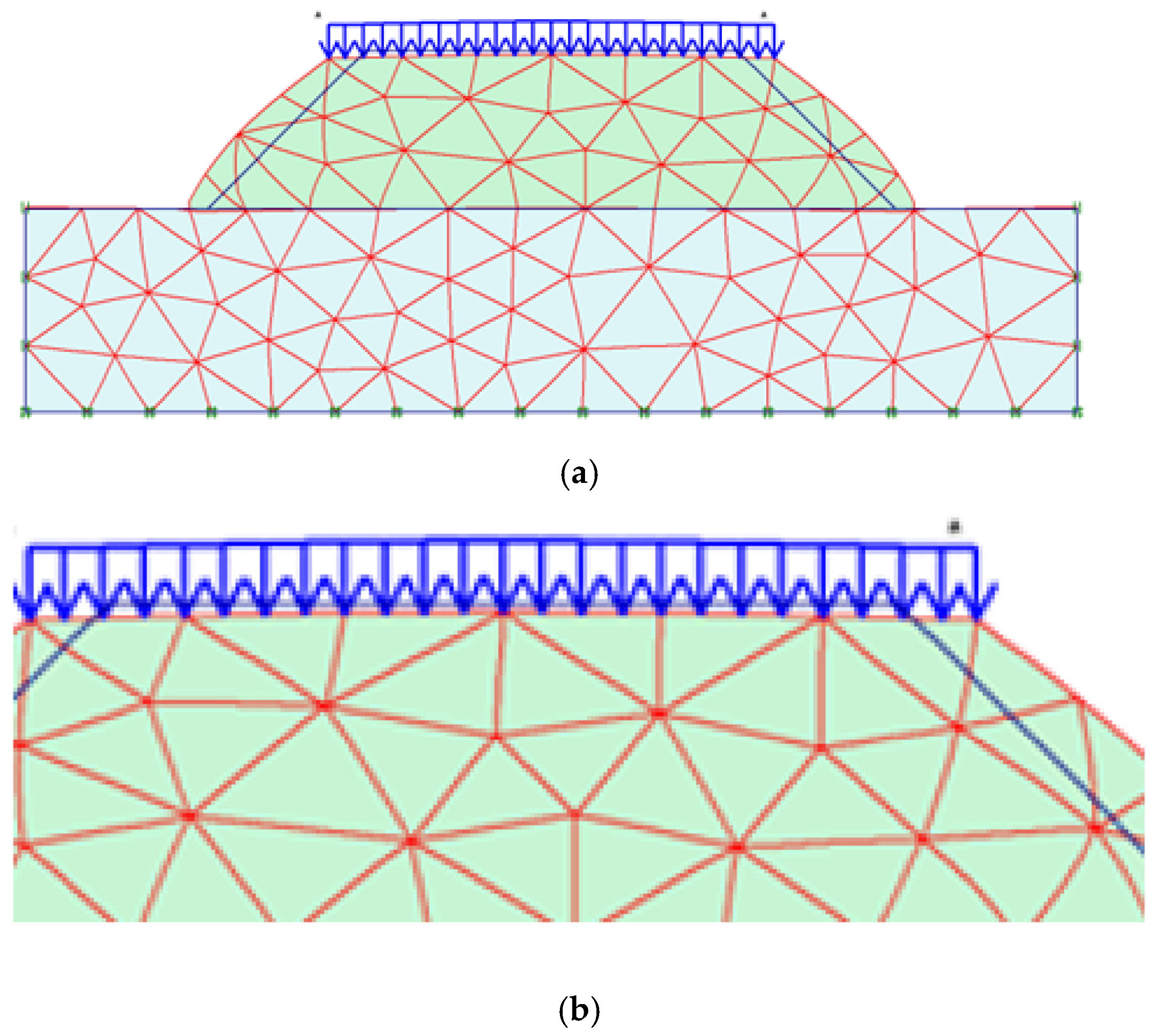
In the revised analysis, finer mesh elements were applied in the critical pile–soil interaction zone and around the loading area.
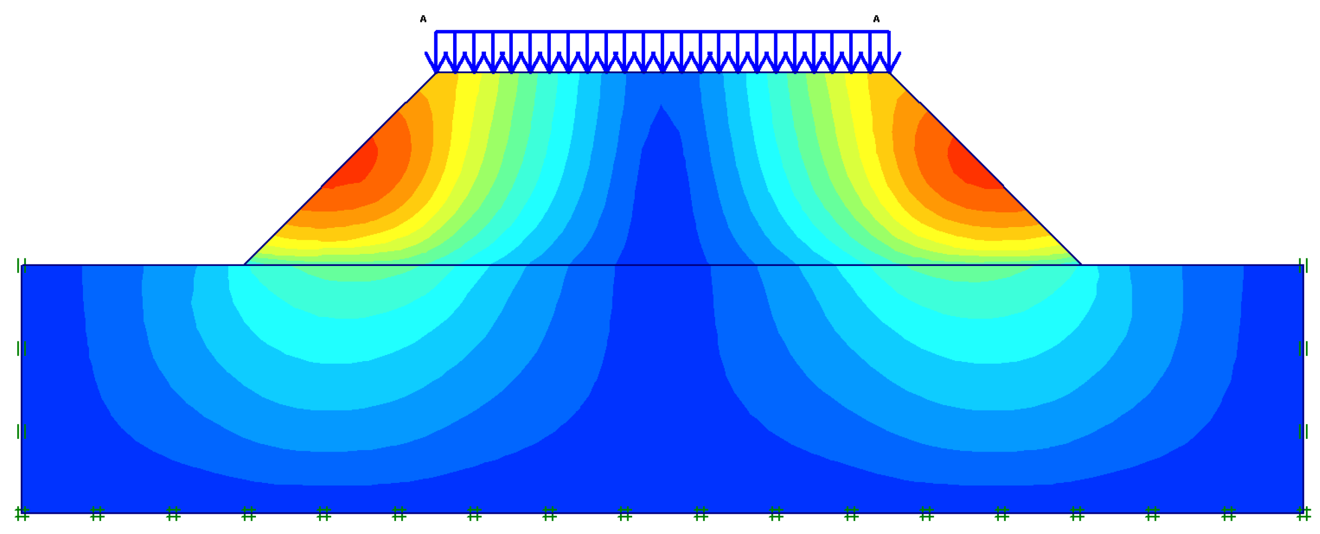
Figure 4 and
Figure 5 are updated to include zoomed-in views, which clearly show the mesh clustering in these critical regions. Furthermore, a mesh sensitivity analysis was performed using three different mesh densities. The results indicated that refining the mesh beyond the adopted configuration changed the settlement and FS values by less than 3%. Therefore, the selected mesh was confirmed to be sufficiently refined to ensure numerical accuracy while avoiding unnecessary computational cost (
Table 4).
A mesh sensitivity analysis demonstrated that further refinement beyond the adopted mesh produced negligible changes (<3%) in the settlement and FS values.
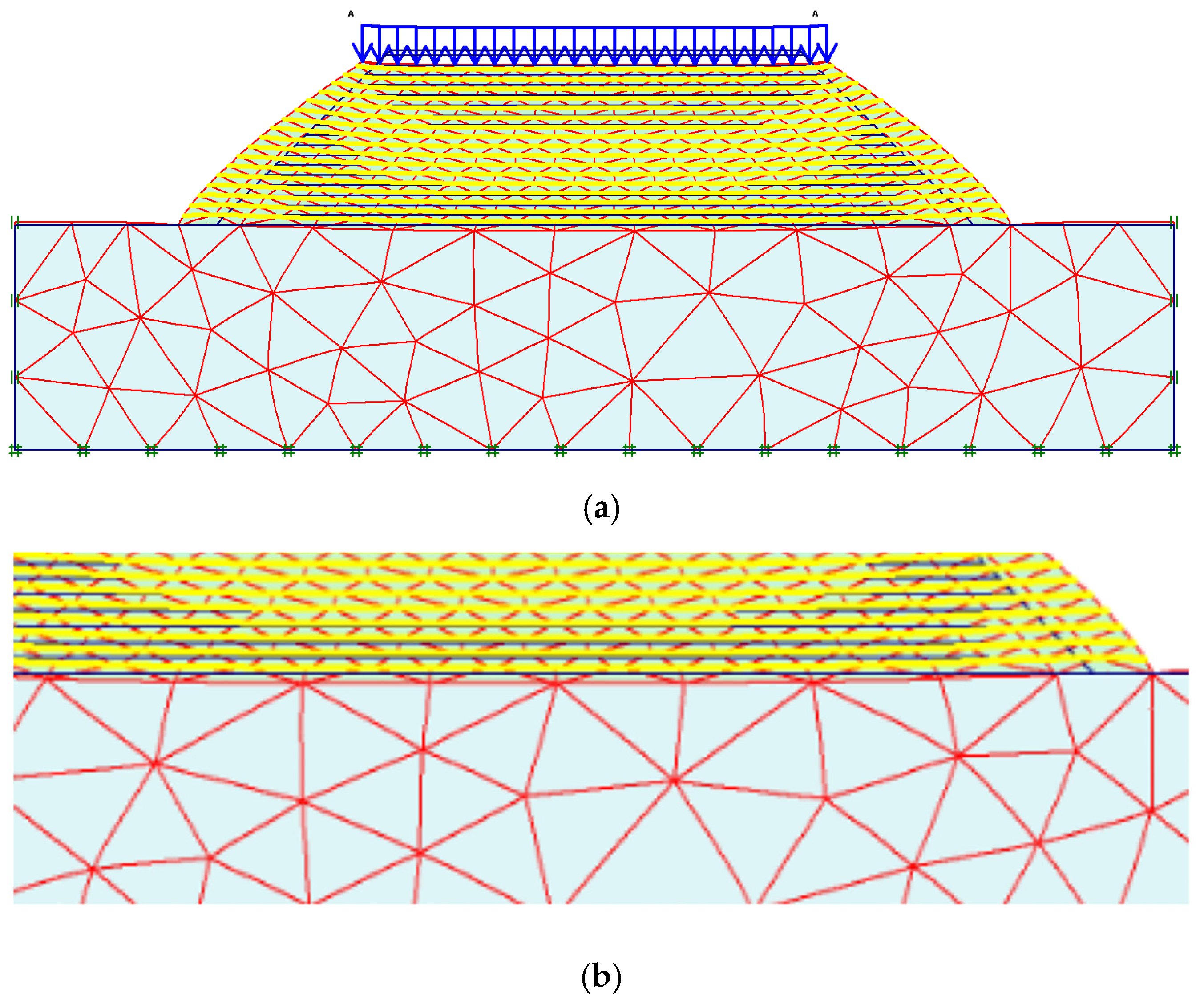
In the unreinforced situation, the calculations were performed in two stages. In the first stage, the initial stresses due to the ground self-weight were composed, and in the second phase, the phi-c reduction analysis was performed. In the reinforced condition, the geogrid reinforcement was activated, and the calculations were conducted. For the finite element analysis, the model geometry assumed is indicated in
Figure 4a,b. The embankment slope is 1 horizontal/1 vertical, the embankment height is nearly 17.5 m, and the distance where the embankment settles on the foundation soil is 76 m.
3. Results and Discussion
In this section, the analysis results of the unreinforced and reinforced road embankment are presented. Analyses were conducted using the finite element method. FSs and displacements were found using the strength reduction method in the FEM analysis. The strength reduction method was typically employed for the evaluation of slope stability, where a Mohr–Coulomb or similar material model was predominantly employed. Thus, cohesion and the friction angle were decreased to evaluate the slope stability.
3.1. Unreinforced Analyses
In the unreinforced analyses, firstly, the displacement and stress values were obtained under the traffic load, and in the second step, the FS value was obtained by the strength reduction method. In the strength reduction method, the shear strength parameters c and ϕ were reduced until the slope collapsed.
From the analyses, the total displacements in the system were obtained as 26.72 cm. (
Figure 5a,b and
Figure 6). The FS value of the embankment slope was found to be FS = 1.12.
When the results were evaluated, it was observed that the acquired displacement values are outside the allowable limits, similar to the situation in the field, and the FS value of the embankment slope in the static condition is quite low. Accordingly, it becomes necessary to improve the natural soil with low bearing capacity and to increase the FS.
As a natural soil improvement method, the jet grout method was selected because of the presence of alluvial soil units and its lower cost compared to other methods. The jet grout method aimed to create rigid areas within the natural ground and thus to obtain higher bearing capacity values and lower settlement values. Uncontrolled embankment units have a fairly large height in the field (approximately 17.50 m). Uncontrolled filling should be excavated and compacted in layers with a suitable filling material in accordance with engineering techniques. Considering the high slope angle, it was decided to place geogrid material at certain depths between the fill layers in order to increase stability. With the use of geogrids, it is expected that the stresses formed by the traffic load and the embankment’s own weight will spread to a wider area along the geogrid planes and show a more stable behavior.
3.2. Effect of Jet Grout Column Length
In this study, analyses were carried out using different length values to determine the optimum value of jet grout column lengths. The obtained displacement and safety factor values are shown in
Table 5. In the analyses, the column diameters were set as 60 cm, and the center-to-center column spacing was fixed at 2 m × 2 m.
When the results of the analysis are investigated, it is observed that the largest total displacement value is obtained when the jet column lengths are 5 m. In cases where the jet column lengths are 10 m and 15 m, the displacement values are very close to each other and decrease by approximately 65% compared to L = 5 m.
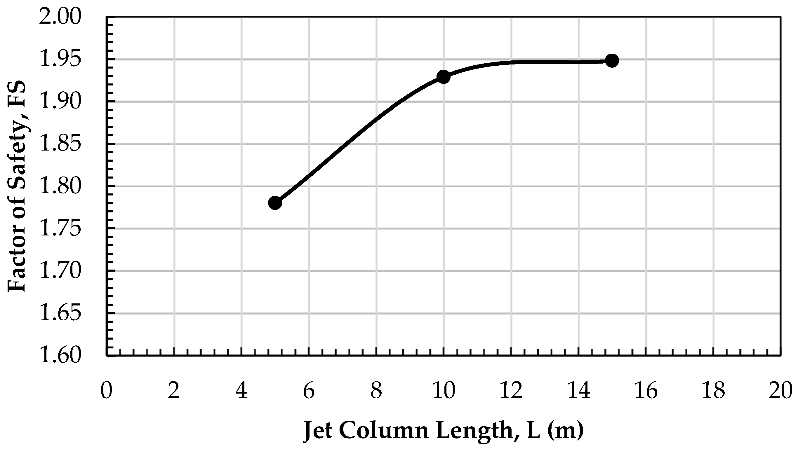
When the correlation between jet column length and FS is examined, the lowest FS value is obtained when the jet column lengths are 5 m. In cases where the jet column lengths are 10 m and 15 m, the FS values are very close to each other and increase by approximately 5% and 10%, respectively, compared to the L = 5 m situation (
Figure 7 and
Figure 8).
According to the values obtained from the analyses of the jet column lengths, considering the total displacements and safety factors, the optimum length of the jet column is determined as L = 10 m.
As the jet column lenght increases, the rigid regions formed within the natural ground increase in size, which causes the displacement values to decrease. In addition, traffic and embankment loads are transmitted to deeper soil layers, which also causes the bearing capacity to increase.
3.3. Model Validation
To strengthen the credibility of the numerical model, the obtained settlement and factor of safety (FS) values were compared with values reported in previous studies. Specifically, the findings of Borges and Marques [
28] and Cheng et al. [
29] were used as benchmarks. The comparison demonstrates that the maximum settlement predicted in this study (43–46 mm) is highly consistent with the values reported by Borges and Marques (45 mm) and Cheng et al. (48 mm) [
28,
29]. Similarly, the FS values obtained (1.65–1.70) are within the literature range of 1.65–1.72. This close agreement confirms that the present numerical framework can reproduce realistic settlement and FS values. While this comparative exercise provides partial validation of the model, we acknowledge that comprehensive field monitoring remains necessary for full validation (
Table 6).
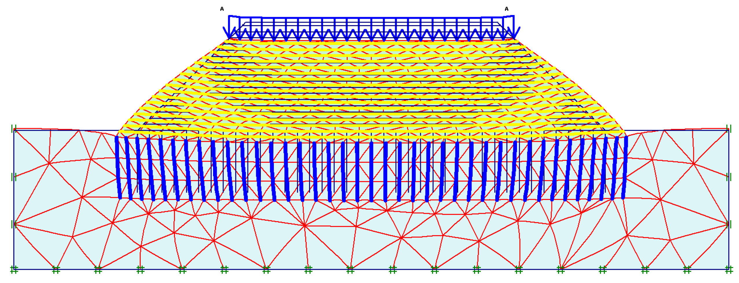
The finite element mesh was discretized using 15-node triangular elements in plane strain conditions. Mesh refinement was particularly applied in the critical regions, including the embankment toe, the loading zone, and around the jet grout columns. As illustrated in
Figure 4b and
Figure 5b, the refined mesh clustering in these areas is clearly shown, whereas
Figure 4a and
Figure 5a present the overall mesh discretization.
The comparison shows that the settlement and FS values obtained in this study are in close agreement with the values reported in the literature.
3.4. Parametric Analysis
In addition to the validation process, a limited parametric analysis was conducted to assess the sensitivity of the model to key geotechnical parameters. Two scenarios were examined, namely, (i) increasing the pile diameter by 20% and (ii) reducing the soil modulus by 10%. The analysis demonstrated that increasing the pile diameter reduced settlement from 44 mm to 37 mm and increased the FS from 1.68 to 1.80. Conversely, decreasing the soil modulus resulted in higher settlement (49 mm) and a reduced FS (1.58). These results align with theoretical expectations, confirming that the developed model realistically captures the effect of parameter variations on geotechnical performance.
3.5. Effect of Geogrid Layer Spacing
The embankment has a fairly large height in the field (approximately 17.50 m). Embankment fill should be excavated and compacted in layers with a suitable filling material in accordance with engineering techniques. Considering the high slope angle, it was decided to place geogrid material at certain depths between the fill layers in order to increase stability.
In this section, analyses were carried out using different spacing values of the geogrid layers. The geogrids were placed at intervals of h = 0.50–1.00–1.50–2.00 m, the FS values were obtained, and the optimum geogrid spacing value was determined (
Table 7).
Table 4 shows that the FS of the slope rises more than 2 times when reinforcement layers are placed inside the fill slope. As can be seen in
Figure 9, the FS of the slope decreases as the distance between the geogrid layers increases. Although the highest FS is obtained when the distance between geogrids is 0.50 m, the distance value between the geogrid layers was chosen as 1 m, considering both conventional applications and economics.
The deformed mesh obtained from the analysis of the geogrid-reinforced embankment is shown in
Figure 10.
The mesh sensitivity analysis confirmed that further refinement produced negligible changes (<3%) in settlement and the FS values (
Table 4). Therefore, the adopted mesh configuration (
Figure 4a,
Figure 5a and
Figure 10a) with refinement in critical areas (
Figure 4b,
Figure 5b and
Figure 10b) was considered sufficiently accurate for the analyses.
3.6. Analyses Using Optimum Parameters
Table 8 shows the parameters of the geogrid placed in the embankment and the jet grout improvement applied to the foundation soil. The values were obtained as a result of the analysis performed.
As a result of the analysis using the optimum values given in
Table 4, the safety factor in the reinforced case was obtained as FS = 2.48, and the total displacements were obtained as s = 9.45 cm. Compared to the unreinforced case values (FS = 1.12 and s = 26.72 cm), it was determined that the safety factor increased by approximately 220% and the total displacement value decreased by approximately 65%.
When the obtained results are evaluated, it is seen that the displacements are reduced and the bearing capacity of the ground is increased due to the reinforcement of the natural ground using the jet grout columns. In addition, by placing geogrid material into the slope, it is seen that the stresses caused by both traffic load and backfill weight are spread over a wider area along the geogrid plane, and a wider sliding surface is obtained. This increases the stability of the embankment slope and allows higher safety factors to be obtained.
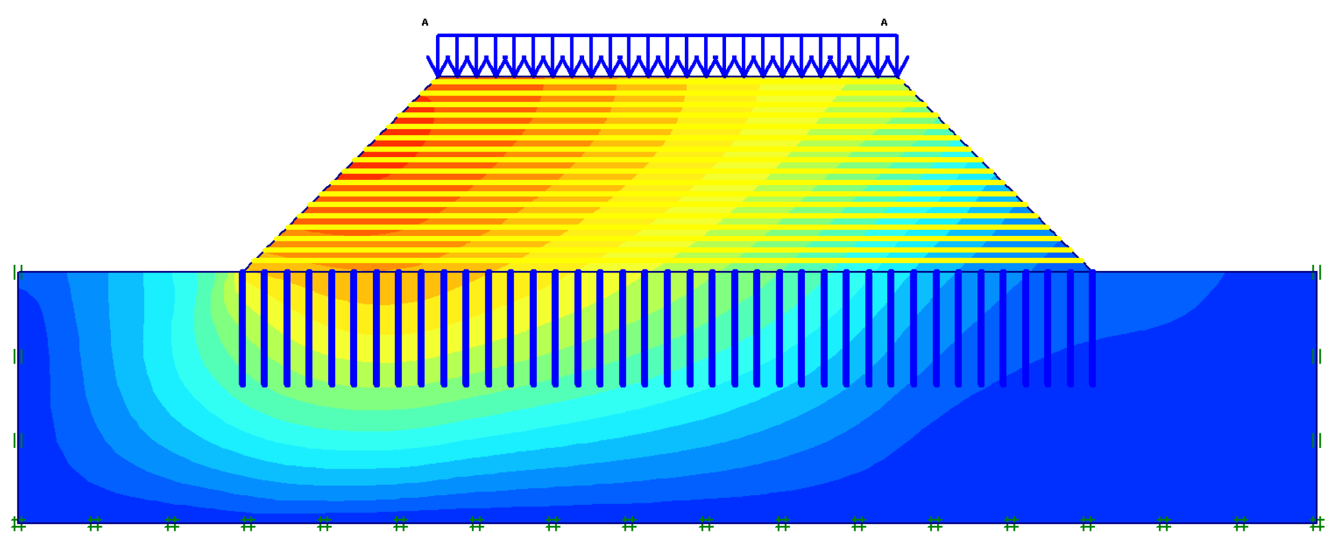
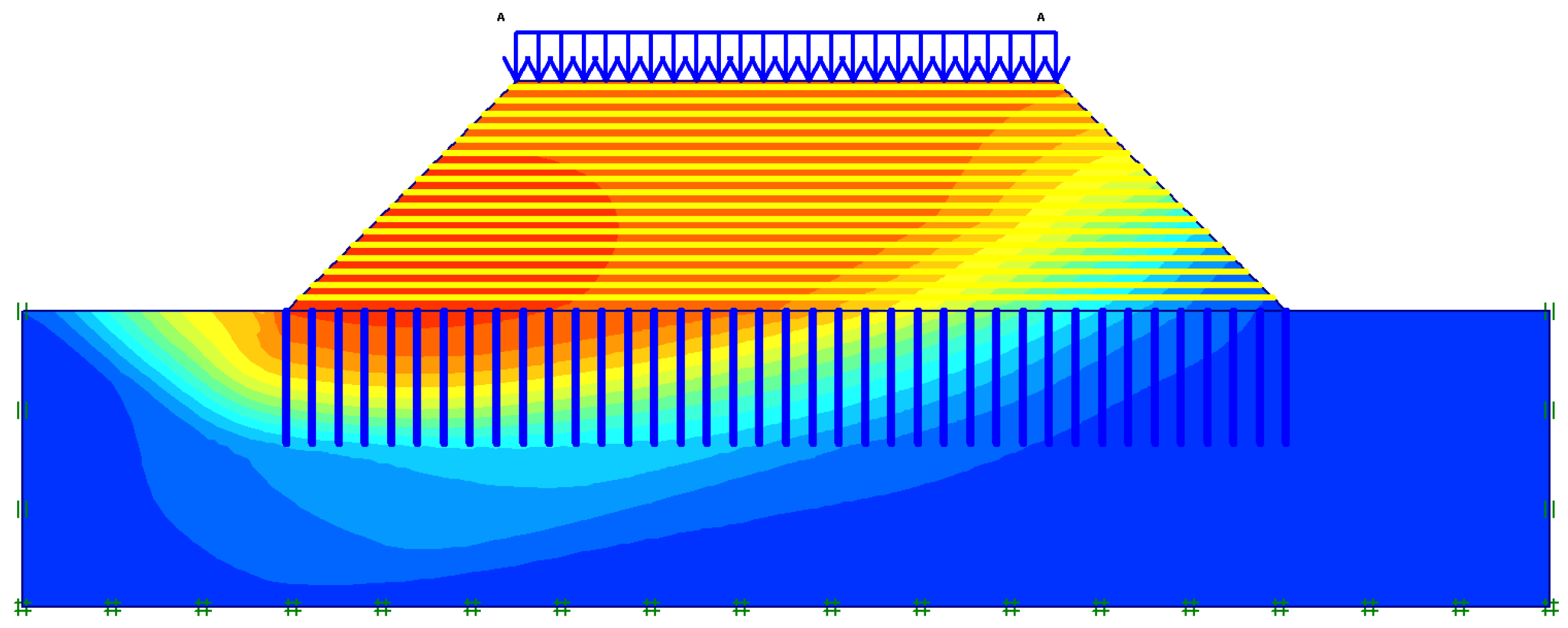
The model geometry, deformed mesh, and total displacement contours obtained from the analysis of the reinforced soil and embankment are shown in
Figure 11,
Figure 12 and
Figure 13.
3.7. Pseudo-Static Analyses
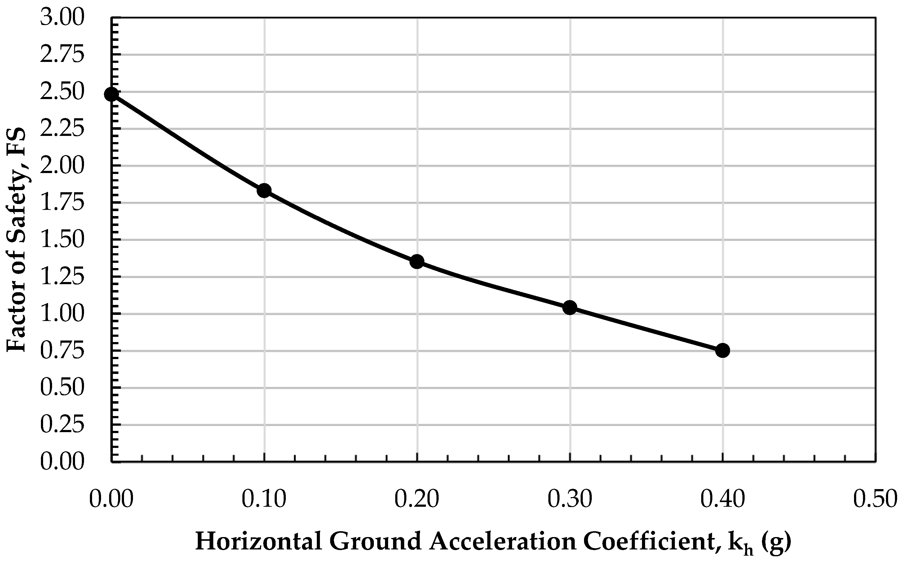
Dynamic analyses were carried out by changing the horizontal ground accelerations on the reinforced soil. The results obtained are given in
Table 9 and
Figure 14. From
Table 5 and
Figure 14, it can be seen that the safety factor values decrease rapidly depending on the increase in the horizontal ground acceleration coefficient value. It was observed that when the horizontal ground acceleration coefficient was 0.30 g, the safety factor value (1.04) was at the limit, and when the horizontal ground acceleration coefficient was 0.40, collapse occurred in the embankment. Pseudo-static analyses were performed in PLAXIS by applying equivalent horizontal seismic forces defined as k
h·W, where k
h is the horizontal seismic coefficient (0.1–0.4) and W is the soil weight. The same boundary conditions used in the static analyses (u
x = 0, u
y = 0 at base; u
x = 0 at vertical boundaries) were maintained. The phi-c reduction procedure was then applied to evaluate the factor of safety (FS) under these seismic conditions.
The obtained settlement and FS values were compared with values reported by Borges and Marques [
28] and Cheng et al. [
29], showing a consistent trend. While this provides a partial validation of the model, future field monitoring is required for comprehensive validation.
4. Conclusions
This study examined the stability and displacement issues observed in a road embankment constructed on weak soil, employing field and laboratory tests to characterize soil properties. Finite element method (FEM) simulations were conducted to analyze bearing capacity, displacement, and overall stability under both static and dynamic loading conditions. The results presented here are valid within the context of the specific soil conditions, loading scenarios, and modeling assumptions considered in this case study. Based on the findings, the following conclusions can be drawn.
The comparison between the unreinforced and reinforced cases clearly shows that the application of geogrid reinforcement combined with jet grout columns significantly improves the engineering performance of both the embankment and its foundation soil. The geogrid acts to reinforce the embankment through interlocking and frictional resistance mechanisms with the fill material, effectively creating a composite system that enhances slope stability and increases the factor of safety (FS). Similarly, the installation of relatively stiff jet grout columns improves the foundation’s bearing capacity and reduces settlement by transferring loads to deeper, more competent soil layers. This computational approach facilitates the optimization of reinforcement parameters to achieve improved performance with cost efficiency. Although the effects of jet column length and geogrid spacing were analyzed, a more extensive parametric investigation would provide additional insights into reinforcement performance, which remains beyond the scope of this study.
Quantitative analysis revealed a substantial improvement in stability and deformation control. The safety factor increased from 1.12 in the unreinforced condition to 2.48 following reinforcement, representing an approximate 220% increase. Total displacement decreased from 26.72 cm to 9.45 cm, which corresponds to a 65% reduction in settlement. These improvements suggest that the combined reinforcement techniques can substantially enhance the durability and service life of embankments on weak soils, reducing maintenance costs and mitigating failure risks.
Dynamic analysis under seismic loading indicated that the embankment’s safety factor decreased with increasing horizontal ground acceleration, as expected. At a horizontal acceleration coefficient of 0.30 g, the safety factor approached the critical threshold (FS = 1.04), indicating marginal stability. Beyond this, at 0.40 g, the embankment was predicted to fail, emphasizing the importance of considering seismic effects in the design of reinforced embankments, particularly in regions prone to earthquakes.
The finite element method proved to be an effective tool for simulating the complex interaction between soil, reinforcement materials, and structural loads, providing valuable insights into displacement patterns, stress distributions, and failure mechanisms. This computational approach facilitates the optimization of reinforcement parameters to achieve improved performance with cost efficiency.
While the numerical results are promising, it is critical to validate the model through in situ monitoring after the implementation of reinforcement measures. Field validation will help to calibrate the numerical model and ensure the practical applicability and reliability of the proposed stabilization techniques.
In summary, the combined use of geogrid reinforcement and jet grout columns offers an effective solution for enhancing the stability and serviceability of road embankments over weak soils. This integrated approach aligns with current engineering best practices aimed at sustainable infrastructure development, especially in geotechnically challenging environments. The limitations of this study include the use of the simplified Mohr–Coulomb constitutive model, the absence of comprehensive field validation, and a limited parametric scope. Future work should address these issues by employing advanced constitutive soil models, broader parametric analyses, and in situ monitoring to validate numerical predictions.
In addition to the technical improvements observed, the combined application of geogrid and jet grout reinforcement contributes to sustainable infrastructure development. By significantly reducing settlements and increasing the service life of embankments, this approach minimizes the need for frequent maintenance and material replacement. Consequently, it enhances resource efficiency, lowers long-term costs, and supports the construction of resilient and durable transportation systems in geotechnically challenging environments.

