Abstract
Chinese coalbed methane (CBM) reservoirs exhibit characteristically low recovery rates due to adsorbed gas dominance and “three-low” properties (low permeability, low pressure, and low saturation). CO2 thermal drive (CTD) technology addresses this challenge by leveraging dual mechanisms—thermal desorption and displacement to enhance production; however, its effectiveness necessitates uniform fracture networks for temperature field homogeneity—a requirement unmet by conventional long-fracture fracturing. To bridge this gap, a coupled seepage–heat–stress–fracture model was developed, and the temperature field evolution during CTD in coal under non-uniform fracture networks was determined. Integrating multi-cluster fracture propagation with stress barrier and intra-stage stress differential characteristics, a stress-barrier-responsive diverting fracturing technology meeting CTD requirements was established. Results demonstrate that high in situ stress and significant stress differentials induce asymmetric fracture propagation, generating detrimental CO2 channeling pathways and localized temperature cold islands that drastically reduce CTD efficiency. Further examination of multi-cluster fracture dynamics identifies stress shadow effects and intra-stage stress differentials as primary controlling factors. To overcome these constraints, an innovative fracture network uniformity control technique is proposed, leveraging synergistic interactions between diverting parameters and stress barriers through precise particle size gradation (16–18 mm targeting toe obstruction versus 19–21 mm sealing heel), optimized pumping displacements modulation (6 m3/min enhancing heel efficiency contrasted with 10 m3/min improving toe coverage), and calibrated diverting concentrations (34.6–46.2% ensuring uniform cluster intake). This methodology incorporates dynamic intra-stage adjustments where large-particle/low-rate combinations suppress toe flow in heel-dominant high-stress zones, small-particle/high-rate approaches control heel migration in toe-dominant high-stress zones, and elevated concentrations (57.7–69.2%) activate mid-cluster fractures in central high-stress zones—collectively establishing a tailored framework that facilitates precise flow regulation, enhances thermal conformance, and achieves dual thermal conduction and adsorption displacement objectives for CTD applications.
1. Introduction
Despite abundant reserves and significant development potential, China’s coalbed methane (CBM) resources face substantial extraction challenges [1,2,3]. The gas exists predominantly in adsorbed states with minimal free gas content, while most reservoirs exhibit “three-low” characteristics: low gas pressure, low saturation, and low permeability [4,5,6]. These properties result in formidable extraction difficulties and suboptimal recovery rates, necessitating continuous development of novel enhancement techniques to improve CBM well productivity [7].
Thermal stimulation represents a viable alternative to pressure depletion for enhancing CBM desorption. This has prompted proposals for integrated thermal–CO2 injection to improve CBM recovery efficiency, leveraging dual mechanisms [8,9]: (1) thermal conduction and convection from heated CO2 elevates coal seam temperature, accelerating methane desorption through energy activation [10,11,12]; (2) thermally induced fracturing enhances coal permeability [13,14,15]. Despite these advantages, thermal–CO2 co-injection remains nascent, with research currently confined to theoretical and numerical investigations. Notably, Fang et al. [16] established a fully coupled thermal–hydraulic–mechanical (THM) model for CO2-CH4 displacement, analyzing temperature effects and permeability evolution under varying injection pressures and production well temperatures. Applying Qinshui Basin parameters, Ma et al. [17] simulation of thermal–CO2 injection determined that effective influence radii increase with injection duration and pressure, exhibiting power-law dependence on injection time and linear correlation with injection pressure—quantitatively validating the method’s scalability.
Consequently, the production mechanism of CO2 thermal drive (CTD) fundamentally differs from conventional drainage-based stimulation, necessitating distinct fracture network design criteria compared to standard hydraulic fracturing [18,19,20,21]. Whereas current CBM fracturing prioritizes creating high-conductivity pathways (“building roads”) focused on fracture length and conductivity, CTD requires constructing uniform thermal exchange fields optimized for fracture density, specific surface area, and thermal conformance efficiency [22,23]. This paradigm shift demands fractures that function not merely as gas conduits but as integrated heat-transfer and CO2-diffusion media [24,25]. Applying conventional fracture networks to CTD operations risks rapid breakthrough along dominant fractures, establishing preferential CO2 flow channels that restrict thermal penetration to narrow coal seams adjacent to fractures. Consequently, limited heat transfer prevents comprehensive CH4 desorption from internal matrices, resulting in suboptimal recovery enhancement [26,27,28]. Moreover, such preferential flow leads to early CO2 breakthrough, drastically shortening its residence time within the reservoir and severely limiting its potential for permanent sequestration.
This demonstrates that CTD requires not just fractures, but an efficient, stable, and fully covered thermal chemical reactor that simultaneously enhances methane recovery and functions as a carbon storage site [29]. Constructing this reactor necessitates updating fracturing design principles, specifically using the dual objectives of heat transfer and adsorption–displacement to guide fracture network design. A uniform fracture network is critical for carbon sequestration, as it promotes a more extensive and evenly distributed contact area between injected CO2 and the coal matrix. This significantly prolongs the residence time of CO2 by mitigating rapid channeling, thereby providing the necessary duration for effective adsorption and eventual trapping within the coal seam. Supporting process enhancements are needed to ensure uniform fracture propagation [30,31,32]. Thus, existing fracturing technologies require further research to develop tailored CTD fracture network optimization technologies that explicitly address both enhanced gas recovery and sequestration efficiency [33]. However, the interplay between thermal effects, fluid flow, mechanical deformation, and fracture propagation under non-uniform fracture networks remains poorly understood, particularly in the context of CTD. This gap raises a critical research question: How can we design and optimize a fracture network that effectively accommodates the coupled processes of seepage, heat transfer, stress redistribution, and fracture evolution to achieve efficient and uniform thermal stimulation and CO2 sequestration in CBM reservoirs. To achieve this, an innovative fracture network design theory driven by the dual mechanisms of thermal transfer enhancement and adsorption–displacement synergy was proposed. This is supported by geologically responsive models for precise fracture control, ultimately forming a dedicated CTD fracturing technology system. This provides theoretical and technical support for coal seam carbon storage and enhanced energy recovery.
To bridge this gap, a coupled seepage–heat–stress–fracture model was developed, which integrates key physical processes relevant to hydraulic fracturing design, including fluid flow within fractures and matrix, heat convection and conduction, rock deformation, and fracture initiation and propagation. This model enables the determination of the temperature field evolution during CTD in coal under non-uniform fracture networks. The significance of this coupled model lies in its ability to quantitatively evaluate the impact of fracture network characteristics on heat distribution, CO2 migration, and stress evolution, thereby providing a scientific basis for optimizing hydraulic fracturing design in CTD applications. Integrating multi-cluster fracture propagation with stress barrier and intra-stage stress differential characteristics, a diverting agent technology to enhance fracture network uniformity was proposed. Furthermore, by analyzing stress shadow effects across injection rates, optimized pumping schedules were established to balance thermal drive efficiency against stress shadow mitigation. This integrated approach develops a stress-barrier-responsive diverting fracturing technology specifically designed for CTD temperature field requirements. The findings provide critical guidance for optimizing fracture flow distribution, improving network uniformity, enhancing heat transfer efficiency, and achieving CTD’s dual objectives of heat transfer and adsorption–displacement.
2. Methods
2.1. Fracture Propagation Model
2.1.1. Flow Equation of Fracturing Fluid in Fractures
Consider fracturing fluid as an incompressible power law fluid, the flow equation satisfies the following [34]:
where p and q(t) denote fluid pressure and flow rate, respectively; s(x, y) represents the distance along the fracture propagation direction; ww is the average fracture width; and hf(s, t) is the current fracture height. The flow behavior index and consistency coefficient are denoted by n′ and K, respectively.
The local continuity equation and the mass conservation equation can be expressed as follows [35]:
where ql(t) is the filtration loss of fracturing fluid; hl is the height of the filtration layer; cl is the total filtration coefficient; t0(s) is the initial time when the fracturing fluid flows to each fracture unit; L(t) is the length of the current crack.
2.1.2. Heat Transfer Model
Heat is primarily transferred through conduction and convection. Heat conduction is driven by a temperature gradient and can be described by Fourier’s law (Equation (5)):
where qT is the thermal flux (W/m2), λ is the thermal conductivity (W/m·K), and T is the temperature (K).
Heat convection primarily occurs via fluid flow through porous and fractured media, with conduction. Solving the temperature field requires the energy conservation equation (Equation (6) for the coal matrix; Equation (7) for fractures). Within fractures, convective transport significantly dominates conductive transport. Therefore, conduction can be neglected in fractures for simplification [36].
ρt and ρf denote the densities of the rock and fluid, respectively (kg/m3); Tf and Tp represent the temperatures within the fracture and coal matrix, respectively (K); Cₜ and Cf are the heat capacities of the rock and fluid, respectively (J/(kg·K)); qst stands for the heat source term in both the coal matrix and fractures (J/s).
Heat exchange between the matrix and the fractures also consists of convection and conduction, which can be described by Equation (8):
where qT,ex is the heat exchange between the matrix and the fractures (J/s), and f3 is the thermal infiltration factor (1/m).
2.1.3. Reservoir Stress Balance Model
Based on solid mechanics theory, consider an infinitesimal hexahedral element within the reservoir domain. Assuming it is in a state of static equilibrium and neglecting inertial forces, the stress equilibrium equations in the x, y, and z directions can be expressed as follows [37]:
where σx, σy, σz, σx, τxy, τyz, and τzx are the total stress components; ρr is the reservoir rock density, such that ρrg represents the body force due to rock self-weight.
According to the effective stress theory, the total stress sustained by a porous rock medium comprises two components: the effective stress σeff transmitted through the rock matrix skeleton and the mean pore fluid pressure p:
where α is the effective stress coefficient, and m equals 1 for normal stress components and 0 for shear stress components. Thus, the stress equilibrium equations in the x, y, and z directions can be rewritten as follows:
2.1.4. Fracture Propagation Criterion
According to the principles of the indirect boundary element method (IBEM), within an infinite formation domain, the two surfaces of a hydraulic fracture can be treated as internal boundaries of the medium, denoted as S+ and S−. Displacement discontinuities across these fracture surfaces, Dn (normal) and Ds (tangential), represent relative displacements between S+ and S−.
By discretizing the hydraulic fracture into a series of small boundary elements with semi-length a, the stress state at element i can be expressed as the superposition of influences from all tangential and normal displacement discontinuities across the fracture elements [38]:
where Dsj and Dnj represent the tangential and normal displacement discontinuities at element j, respectively; and Aij denotes the boundary elastic influence coefficient of the displacement discontinuity at element j on element i, which can be determined by the following equation:
where dij is the distance between elements i and j, h is the fracture height, and α and β are fitting parameters.
Under the combined action of the fluid net pressure within the fracture and the in situ stresses, the stress equilibrium equation for a fracture element is as follows:
where σH and σh are the maximum and minimum horizontal principal stresses, respectively; pi is the fluid net pressure within fracture element i; and θi is the angle between fracture element i and the x-axis.
The mode-I and mode-II stress intensity factors at the fracture tip element are then determined as follows [39]:
The equivalent force intensity factor can be obtained by the following equation:
where KI and KII are the mode-I and mode-II stress intensity factors at the fracture tip element; Dntip is the normal displacement discontinuity at the along the fracture tip; Dstip is the tangential displacement discontinuity at the fracture tip; a is the semi-length of fracture; r is the radial distance from the fracture tip to the calculation point; Keq is the equivalent force intensity factor; θ is the fracture propagation angle relative to the original crack plane.
2.2. Numerical Model of Temporary Pugging Agent Transport
Based on the Discrete Phase Model theory and solid–liquid two-phase flow characteristics in fracturing, including turbulence effects and fluid–particle interactions, the model assumes the following: ① fracturing fluid is incompressible with constant rheology; ② diverting agents are uniform spherical particles; ③ particles are rigid spheres (no deformation during transport/collisions, as its primary focus was on simulating the macro-scale pressure response and evaluating the overall diversion).
2.2.1. Continuity (Mass Conservation) Equation
2.2.2. Momentum Conservation Equation
2.2.3. Turbulent Equation
Since turbulence is a highly complex nonlinear flow, no universally accurate modeling approach exists. The standard k-ε model, proposed by Launder and Spalding [40], became the most widely adopted turbulence model due to its reliability, moderate computational cost, robust convergence, and acceptable accuracy.
The turbulent kinetic energy (k) equation is as follows:
The equation for turbulence energy dissipation rate ε is as follows:
where k is the turbulent kinetic energy, m2/s2; ε is the turbulent dissipation rate, m2/s2; σk is the turbulent Prandtl number for k (dimensionless, σk = 1.0); ε is the turbulent Prandtl number for ε (dimensionless, σε = 1.3); μt is the eddy viscosity, Pa·s; Gk is the turbulence kinetic energy generated by velocity gradients, kg/(m·s3); c1, c2 are the empirical constants (dimensionless, c1 = 1.44, and c2 = 1.92).
The formula for calculating turbulent viscosity is as follows:
where cμ is the turbulent viscosity coefficient; cμ = 0.09.
2.2.4. Discrete Phase (Particle) Motion Equation
2.3. Model Calculation and Verification
2.3.1. Model Calculation
TOUGH2-Biot employs a modular structure, divided into three specialized modules: thermo-hydro-particle transport, elasto-plastic mechanics, and fracture and damage. Since time evolution is only tracked in the transport module, it also controls the overall simulation. The mechanics module uses the temperature field, along with stress boundary conditions and rock properties, to compute stress and displacement via the nonlinear finite element method. These results are then transferred to the fracture and damage module.
The fracture and damage module explicitly calculates the current fracture-damage state based on the stress conditions from the mechanical module and the fluid pressure from the thermo-hydro-particle transport module. It also computes the resulting additional deformation and permeability changes. The updated permeability is then passed back to TOUGH2, while the additional deformation is returned to the mechanical module for the next coupling iteration (Figure 1).
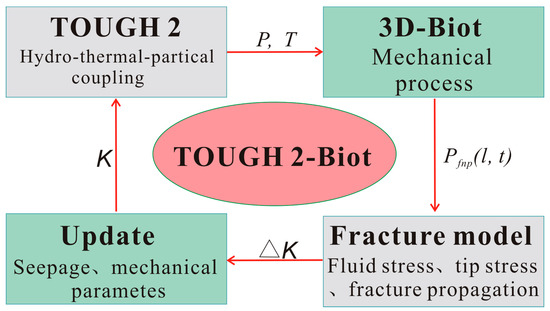
Figure 1.
TOUGH-EPFD3D coupling process of each functional module.
2.3.2. Model Verification
The KGD fracturing model is a mathematical model that can accurately describe and analyze fracture propagation and fluid flow in rock media. This model also assumes that the horizontal plane satisfies the plane strain condition. Therefore, the model with the analytical solution of the KGD model was calibrated.
In the case where the geological conditions and engineering measures of the comparison model are consistent (Table 1), the comparison results indicate that the fracture lengths and widths obtained by the model are in good agreement with the results of the KGD model under the conditions of using the given parameters. Fracturing fluid leakoff into the formation during the hydraulic fracturing results in lower fracture propagation rate and narrower fracture width. Since the KGD model does not consider the leakoff from the hydraulic fracture surface, the fracture length and width obtained from the model calculations are slightly lower than those from the KGD model (Figure 2).

Table 1.
Coal properties, reservoir properties, and geostress distribution used in the fracturing model.
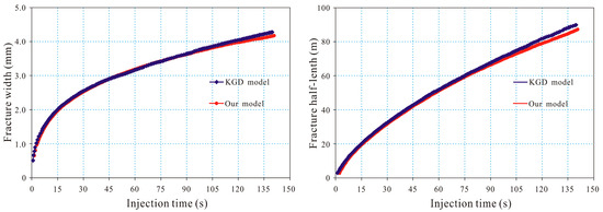
Figure 2.
Comparison of fracture morphology simulated by KGD and the model.
2.4. Construction of Numerical Models
2.4.1. Modeling Geometric of Numerical Model
The H1 horizontal CBM well in the Linfen Block has a true vertical depth of 820.05 m, targeting the No. 5 coal seam. It was completed with a 139.7 mm casing. According to the well testing and stimulation design, the well is planned for an 1800 m fracture stimulation section, divided into 18 stages with an average stage length of 100 m. Each stage employs a three-cluster perforation strategy, with an average cluster spacing of 30 m (Figure 3).
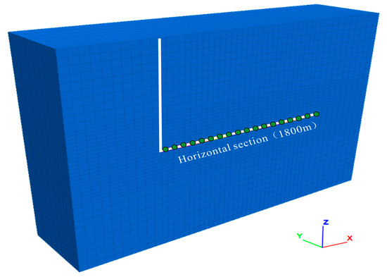
Figure 3.
Geological model of segmented hydraulic fracturing in horizontal well of H1.
Based on the requirements of the mechanical and flow models, the domain was discretized using hexahedral elements. In the x-direction, the mesh was locally refined with an edge length of 35 m, while the extended surrounding region had a coarser resolution of 50 m. Along the y-direction, the mesh expanded outward from y = 0 with a geometric progression ratio of 1.1, totaling 10 layers. The final model consisted of 20,500 elements.
The work has performed a thorough grid independence verification to ensure the accuracy and reliability of our numerical results. A detailed grid sensitivity analysis was conducted by systematically refining the mesh size in both the fracture propagation domain and the near-wellbore region where particle transport and plugging occur.
The verification process compared key output parameters—including fracture length, fracture width at the wellbore, wellbore pressure, and particle placement efficiency—across multiple mesh resolutions. The results became consistent, and changes fell within an acceptable variation threshold (less than 2%) upon reaching a specific mesh density. The final mesh configuration selected for all simulations in this study provides a balance between computational accuracy and efficiency.
2.4.2. Boundary Conditions and Assignment Loading
The numerical model was initialized with a uniform temperature of 40 °C based on field measurements, considering the minimal temperature variation across the thin 8 m coal seam. Initial pore pressure followed hydrostatic equilibrium, yielding 7.85 MPa at the top and 7.93 MPa at the bottom of the formation. Boundary conditions included a free-pressure condition at the symmetry boundary (y = 0) and zero-flux conditions for both temperature and pressure at other boundaries, which were sufficiently distant from the injection zone to avoid interference with fracturing processes.
The stress field in the model was initialized based on field measurements (Table 1), with the maximum horizontal principal stress set at 20.53 MPa, minimum horizontal principal stress at 14.47 MPa, and vertical principal stress (z-direction) at 18.21 MPa. Both x-direction boundaries were assigned as stress boundaries, the y-direction boundary was assigned as the symmetric boundary, and the z-direction boundaries were assigned as the stress boundaries. The initial stress state was established through equilibrium calculations considering gravitational forces and the specified boundary conditions, where the maximum horizontal principal stress was oriented along the x-direction, the minimum horizontal principal stress was oriented along the y-direction, and the vertical stress was oriented along the z-direction. The parameter values presented herein were derived from original experiments performed specifically for this research.
3. Results and Analysis
3.1. Thermal Field Evolution Under Anisotropic Fracture Growth with CO2 Stimulation
The simulation result of the hydraulic fracturing propagation in CBM horizontal wells are shown in Figure 4. The simulation result demonstrates strongly asymmetric hydraulic fracture propagation during staged fracturing in CBM horizontal wells, driven by complex geomechanics: high in situ stress, significant stress differential, and strong heterogeneity.
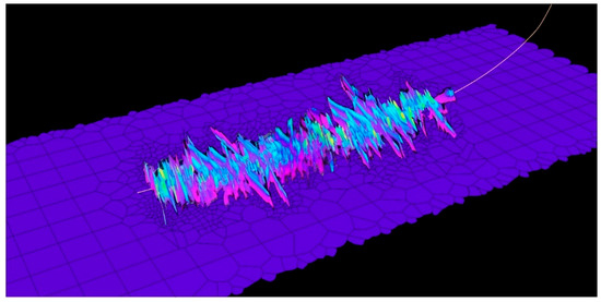
Figure 4.
The hydraulic fracturing propagation of CBM horizontal wells.
Stress heterogeneity is quantified by the differential stress ∆σs between high- and low-stress zones, where a larger ∆σs signifies stronger heterogeneity. Simulations at ∆σs = 5, 8, 12, and 15 MPa demonstrate that in the primary stages, increasing ∆σs reduces near-tip stress in low-stress zones, lowering fracture propagation energy thresholds. This energy gradient drives preferential fluid influx into low-stress regions, inducing progressive fracture asymmetry. Strikingly, significant fracture asymmetry occurs at only ∆σs = 2 MPa, confirming stress heterogeneity’s critical control over hydraulic fracture geometry even under negligible stress differentials (Figure 5).
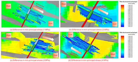
Figure 5.
The non-equilibrium propagation of hydraulic fractures under different stress differences.
Cloud diagrams of thermal field evolution in coal under asymmetric fracture network propagation demonstrate that non-uniform hydraulic fractures cause CO2 to rapidly channel through low-resistance main fractures while bypassing matrix micropores, confining heat transfer to fracture walls without penetrating the coal matrix; this results in coexisting thermal fingers (hot zones along main fractures) and cold islands (in branch-fracture-deficient low-permeability zones) during thermal CO2 injection, where rapid CO2 breakthrough creates localized high-temperature regions while persistent low-temperature areas inhibit CH4 desorption (Figure 6).
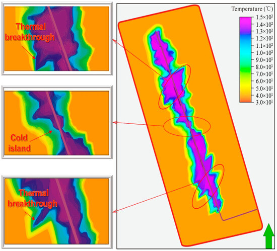
Figure 6.
Cloud diagrams of thermal field evolution under asymmetric fracture network propagation.
Thus, under complex geomechanical conditions such as high in situ stress, significant stress differentials, and heterogeneous stress distribution, hydraulic fracture propagation in coal seams exhibits strong asymmetry. This fracture asymmetry initiates a detrimental cascade: restricted CO2 thermal contact area and distorted thermal fields inhibited CH4 desorption–displacement efficiency, ultimately causing cliff-edge declines in heated CO2 effectiveness. Consequently, establishing a hydraulic fracture network driven by the dual mechanism of “heat-transfer-enhanced adsorption-displacement synergy” requires overcoming this bottleneck by forcibly transforming the fracture equilibrium state.
3.2. Temporary Plugging Simulation for CO2 Thermal-Drive Fracture Networks
Following characterization of temperature field evolution in coal under asymmetric fracture networks during CTD, multi-cluster fracture propagation was analyzed in geologically complex horizontal wells. Transport mechanics and diversion efficiency of temporary plugging agents were quantified across differential injection parameters (displacement, diameter, and concentration).
3.2.1. Mechanisms Governing Asymmetric Propagation in Hydraulic Fracture Networks
Stress Shadow Response to Differential Injection Displacements
Figure 7 presents the contour plot of simultaneous multi-cluster propagation and fracture morphology evolution in a horizontal well. Simulation results reveal pronounced asymmetric hydraulic fracture growth across perforation stages under continuous injection. Heel/toe cluster fractures demonstrate dominant longitudinal extension, while central clusters exhibit constrained propagation. This results in concave fracture geometries with significant propagation asymmetry.
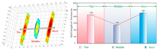
Figure 7.
Evolution of multi-cluster propagation in horizontal wells (Left: fracture morphology; Right: half-length statistics of fractures).
The stress nephogram during multi-cluster propagation in a horizontal well reveals intense inter-fracture stress interference. Stress shadow effects induce concentration at fracture tips during continuous injection, generating biaxial compression that constrains central fractures. Consequently, central fractures must overcome compressive stresses from both heel and toe fractures, resulting in shorter lengths compared to peripheral fractures (Figure 8).
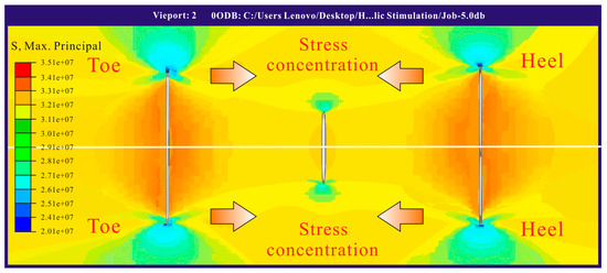
Figure 8.
The stress nephogram during multi-cluster propagation in a horizontal well.
To optimize fracture propagation heterogeneity for CTD requirements, stress shadow effects were simulated across injection rates, with quantitative analysis revealing significant rate sensitivity in fracture network equilibrium. Simulations demonstrate pronounced heel/toe fracture dominance and central constraint at lower displacements (16 and 17 m3/min), forming distinct concave geometries; however, minimal morphological variance occurs among multi-cluster fractures under these low-rate conditions (Figure 9).
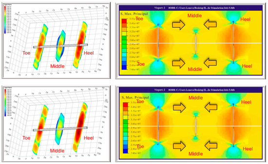
Figure 9.
Cloud map of propagation morphology and stress changes of multi-clusters in horizontal wells (Up: 16 m3/min; Down: 17 m3/min).
Elevating injection displacements to 19–20 m3/min intensified stress shadowing between fracture clusters, inducing complete suppression of central fractures with propagation radii < 50 m and restricted extents. This significantly enhanced propagation heterogeneity across the stimulated horizontal section. Mechanistically, at 20 m3/min, rapid fracture opening concentrates elastic strain energy within the host rock, amplifying both spatial range and magnitude of stress perturbations—thereby exacerbating fracture propagation asymmetry (Figure 10).
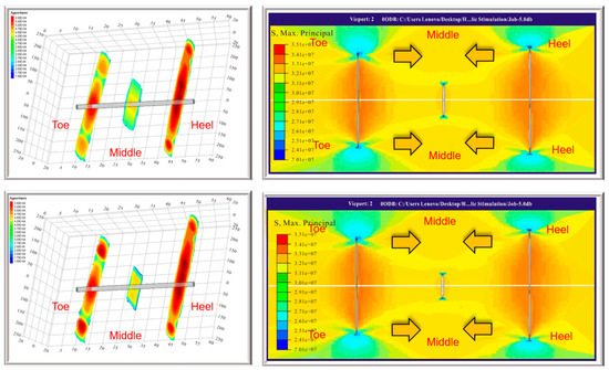
Figure 10.
Cloud map of propagation morphology and stress changes of multi-clusters in horizontal wells (Up: 19 m3/min; Down: 20 m3/min).
Statistical analysis of stress shadow radii across injection displacements demonstrates that elevated rates exacerbate dominant fracture propagation while intensifying dual-stress-interference constraints on central clusters, significantly amplifying propagation heterogeneity (Figure 11 and Figure 12).
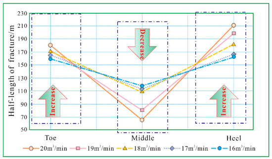
Figure 11.
The propagation length of multi-cluster fractures under different injection displacements.
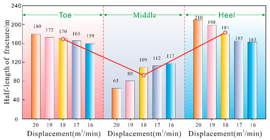
Figure 12.
Histogram of propagation length of multiple clusters under different injection displacements.
Consequently, balancing the positive thermal-sweep efficiency benefits of high-rate flooding against stress-shadow-induced negative effects requires implementing 18 m3/min injection for CBM reservoirs. This rate, combined with temporary diversion, optimizes both displacement efficiency and fracture network conformance.
Intra-Stage Stress Heterogeneity Shielding Effect
Considering stress uniformity development in coal reservoirs, this study analyzes the impact of intra-stage in situ stress heterogeneity on fracture network propagation equilibrium. Intra-stage stress difference (Δσs), defined as the maximum–minimum in situ stress differential within a stage, quantifies heterogeneity. For high-stress clusters, Δσs represents deviation from the stage average. Multi-cluster propagation is examined separately for high stress at heel, middle, and toe clusters due to random spatial occurrence. The in situ stress difference (Δσs) is derived by integrating dipole sonic and density logs with DFIT-calibrated minimum horizontal stress to construct a mechanical earth model for accurate computation.
For the intra-stage stress heterogeneity localized at the heel cluster (i.e., higher minimum horizontal principal stress, σhmin, than other clusters), simulations show that fractures still initiate at Δσs = 1 MPa but exhibit enhanced height growth. At Δσs = 2–3 MPa, heel fracture length decreases markedly while significant fluid diversion to middle/toe clusters progressively increases their fracture lengths (Figure 13).
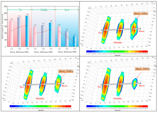
Figure 13.
Hydraulic fracture propagation with intra-stage stress at the heel (Δσs = 1 MPa, 2 MPa, and 3 MPa).
For the intra-stage stress heterogeneity localized at the middle cluster, simulations reveal dual mechanisms of “induced stress” and “stress barriers” that comprehensively suppress fracture propagation. The middle cluster exhibits significantly shorter fracture lengths than other clusters, demonstrating pronounced heterogeneity. At Δσs = 3 MPa, fluid entry into the middle cluster is nearly eliminated. These findings indicate that high-stress localization at central clusters exerts greater impacts on fracture imbalance (Figure 14).
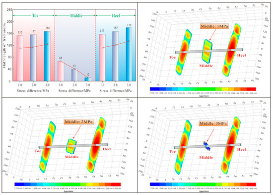
Figure 14.
Hydraulic fracture propagation with intra-stage stress at the middle (Δσs = 1 MPa, 2 MPa, and 3 MPa).
For intra-stage geostress heterogeneity localized at the toe cluster, fracture propagation resembles heel-cluster scenarios. At Δσs = 3 MPa, fluid influx into the toe cluster becomes substantially restricted, exhibiting near-circular fracture geometry. Furthermore, limited toe-zone expansion mitigates the heel cluster’s stress shadow effect, allowing partial propagation recovery in the middle cluster (Figure 15).
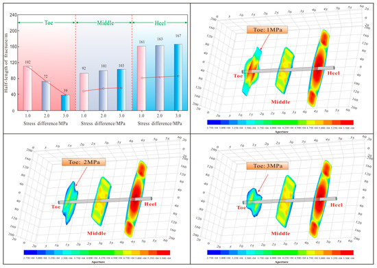
Figure 15.
Hydraulic fracture propagation with intra-stage stress at the toe (Δσs = 1 MPa, 2 MPa, and 3 MPa).
3.2.2. Diverter Particle Migration and Efficiency
Stress shadows and geostress heterogeneity during horizontal well staged fracturing drive non-uniform fracture cluster propagation, reducing CTD efficiency. Temporary plugging diversion is therefore employed to enhance fracture network uniformity. Simulations of three-stage fracturing (7 holes/m; 13 mm perforations) analyzed cluster-specific plugging efficiency versus diverters’ particle size, concentration, and pumping displacement. This establishes temperature-field-driven fracture network design for coal seam CTD optimization.
Effect of Diverters’ Particle Size on Fracture Plugging Efficiency
Figure 16 presents migration trajectories across 16–21 mm diverter particle sizes. Simulations demonstrate that increased particle diameter reduces horizontal migration distance while enhancing accumulation at heel clusters, progressively deteriorating inter-cluster distribution uniformity.
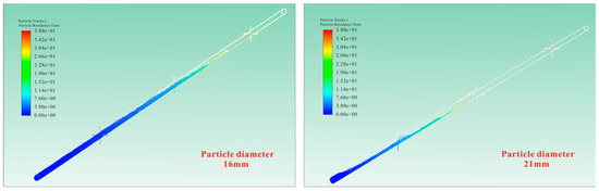
Figure 16.
The migration trajectories across 16–21 mm diverter particle sizes.
Diversion efficiency of diverting particles varies significantly with particle size and wellbore position. At 16 mm, heel efficiency reaches 45.6%, decreasing to 37.5% in middle clusters and 16.3% at the toe. When particle size increases to 25 mm, intensified gravitational forces accelerate settling. Consequently, heel efficiency rises to 71.2%, while middle clusters decrease sharply to 9.4%, and toe efficiency is eliminated (0%) (Figure 17).
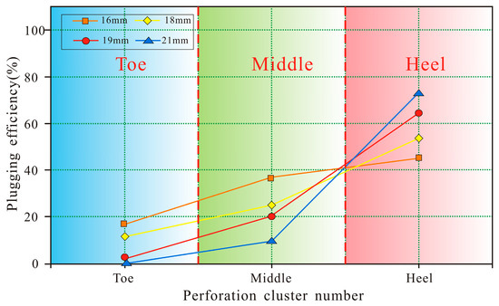
Figure 17.
The cluster diversion efficiency across 16–21 mm diverter particle sizes.
Thus, under constant conditions, larger particles enhance heel diversion efficiency. However, increased particle diameter promotes rapid settling and preferential heel accumulation, severely compromising toe diversion. Conversely, smaller particles exhibit modestly reduced heel effectiveness but achieve broader transport distribution, yielding superior toe diversion performance.
Effect of Pumping Displacements on Fracture Plugging Efficiency
Figure 18 illustrates diverting particle transport behavior at different pumping displacements. Simulation results demonstrate that increasing pumping displacements from 4 to 12 m3/min extends horizontal transport distance, enhancing particle accumulation in toe clusters.
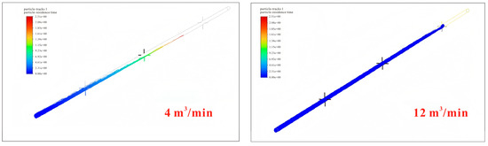
Figure 18.
The diverting particle transport behavior at different pumping displacements.
Simulation results indicate that at low pumping displacements (4 m3/min), reduced wellbore transport velocity and accelerated settling cause diverting particles to accumulate predominantly in heel clusters. This yields 58.6% heel diversion efficiency but complete diversion failure (0%) at the toe due to insufficient particle transport to distal clusters, preventing effective diversion in dominant toe influx zones.
Increasing pumping displacements elevate tubular flow velocity and fracturing fluid turbulence, inducing enhanced random motion of diverting particles that promotes toeward transport. As displacements rise from 4 to 10 m3/min, heel cluster diversion efficiency declines from 58.6% to 29.2%, while toe efficiency increases from 0% to 59.7%. At 12 m3/min, cluster diversion efficiencies stabilize with ≤3% variation relative to 9 m3/min conditions (Figure 19).
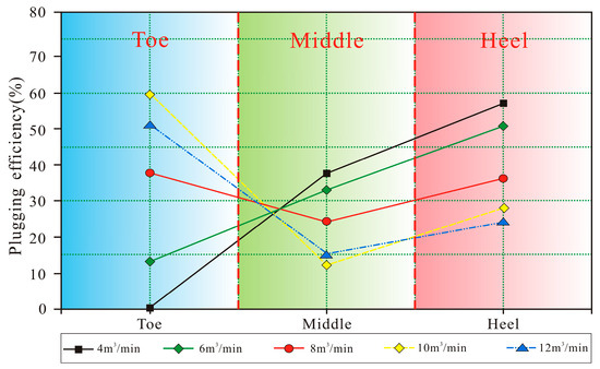
Figure 19.
The cluster diversion efficiency at different pumping displacements.
Consequently, elevated pumping displacements increase diverting particle velocity and momentum, reducing radial entry capacity into trailing clusters. This promotes preferential migration toward the toe section, resulting in higher diversion efficiency in toe clusters than heel clusters during high-rate treatments.
Effect of Diverting Particle Concentration on Fracture Plugging Efficiency
Subsequent simulations evaluated multi-cluster diversion efficiency across particle concentrations. At particle-to-perforation ratios between 0 and 46.2% (particle-to-perforation ratio), heel cluster fluid inflow progressively decreases while middle cluster inflow increases, thereby driving uniform fracture propagation across clusters (Figure 20).
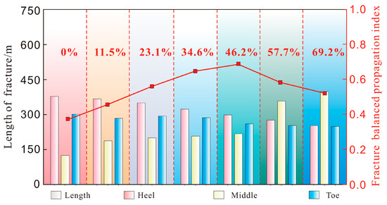
Figure 20.
Comparative of hydraulic fracture length and width under different diverter concentrations.
Within this concentration range, increased particle concentration primarily suppresses dominant heel clusters while activating middle clusters. At the 46.2% equilibrium threshold, optimal diversion is achieved: heel dominance is effectively mitigated, middle clusters are fully activated, and cluster inflow approaches uniformity. Consequently, fracture propagation lengths exhibit convergence toward consistent dimensions (Figure 21).
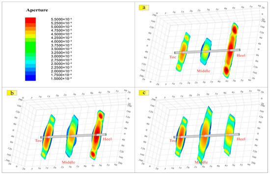
Figure 21.
The fracture propagation under different particle concentrations ((a) 11.5%; (b) 46.2%; (c) 69.2%).
At particle-to-perforation ratios of 57.7–69.2%, the middle clusters become dominant injection zones with extended fracture propagation, while outer cluster growth is suppressed. This shift occurs when particle concentration exceeds the optimal equilibrium threshold (~46.2%), triggering a fundamental behavioral change in diversion mechanisms.
Excessive particle concentration induces over-diversion in outer clusters, progressing from initial advantage suppression to near-complete occlusion. Consequently, fracturing fluid is disproportionately diverted to central clusters, enabling abnormal fracture extension. Conversely, severely restricted fluid access in outer clusters limits propagation, establishing a new imbalanced state characterized by centralized dominance and lateral suppression (Figure 22).
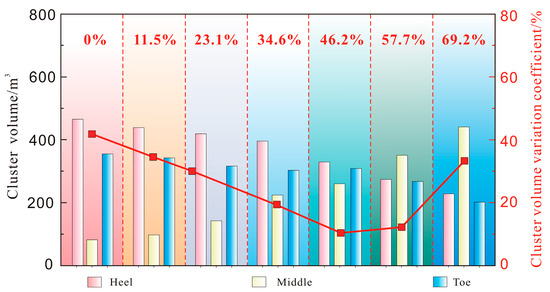
Figure 22.
Injection volume of clusters fluid at different particle concentrations.
Analysis of cluster fluid inflow under varying particle concentrations reveals heel/toe cluster dominance with high inflow and effective fracture propagation at 11.5–23.2% particle-to-perforation ratios, shifting to middle cluster dominance with enhanced propagation at 57.7–69.2%. Optimal fracture network development occurs at 34.6–46.2% concentrations, balancing minimized inflow differential coefficients and uniform fracture morphology across clusters.
3.2.3. Optimizing Diverting Particle Efficiency Through Perforation Cluster Parametric
Fracture propagation behaviors under varying injection displacements and stress differentials, combined with cluster diversion mechanisms, quantify parametric impacts on diversion efficiency. Smaller diverting particles (16–18 mm) exhibit extended horizontal transport, enhancing toe diversion efficiency. Conversely, larger particles (19–21 mm) optimize heel diversion efficiency due to accelerated gravitational settling (Figure 23).
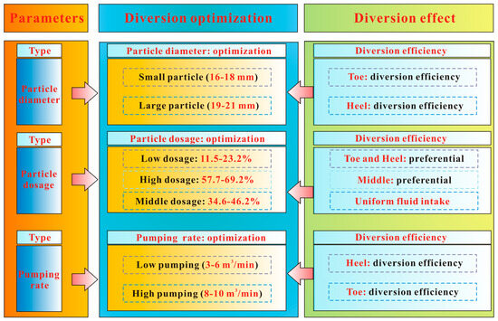
Figure 23.
Transport mechanics and diversion efficiency across differential particle diversion parameters.
Particle concentration governs inflow distribution: 11.5–23.2% ratios enable heel/toe preferential inflow, while 57.7–69.2% concentrations establish middle cluster dominance, with optimal uniformity achieved at 34.6–46.2%. Pumping displacements modulate diversion efficiency—low displacements (≤4 m3/min) enhance heel efficiency through extended gravitational settling residence, whereas high displacements (≥10 m3/min) improve the toe efficiency via extended particle transport distance (Figure 23).
3.3. The Stress-Barrier-Responsive Diverting Fracturing Technology for CTD
The analysis reveals that different temporary plugging parameters exhibit distinct effects on diversion performance across perforation sections, each presenting unique advantages and limitations. Therefore, to optimize parameter selection, a thermal-drive temperature field requirement-driven fracture control technology was proposed. This approach strategically leverages favorable parameter characteristics while mitigating limitations (Figure 24).
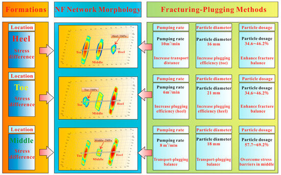
Figure 24.
The stress-barrier-responsive diverting fracturing technology.
To counteract significant stress differences at the heel, temporary toe plugging is implemented to mitigate excessive fluid influx. Effective toe blockage is achieved through three synergistic measures: elevated pumping displacements (10 m3/min) enhance particle transport distance while reducing heel accumulation of blocking agents, thereby improving plugging efficiency; selection of 16 mm spherical diverting particles further increases entry effectiveness; and particle concentrations maintained at 34.6–46.2% optimize fracture propagation balance (Figure 24).
To address significant stress contrast at the toe, a heel-targeted diverting particle is implemented to prevent fluid overload. Effective heel blockage is achieved through the following: a reduced 6 m3/min pumping displacement increasing agent residence time to enhance plugging efficiency; selection of larger 21 mm diverting particles for improved entry effectiveness; and particle concentration maintained at 34.6–46.2% to ensure balanced fracture (Figure 24).
A significant mid-zone stress differential necessitates dual-terminal (heel/toe) diversion to mitigate fluid influx. Effective heel blockage employs 18 mm diverters at 8 m3/min, optimizing the transport–blockage equilibrium. Particle concentration (57.7–69.2%) enhances mid-zone fluid entry to overcome stress barriers (Figure 24).
Building on stress barrier evolution analysis, a diversion strategy integrating particle transport dynamics and sealing efficiency—under variable pump displacements, diameters, and concentrations—is developed. This approach establishes CO2–thermal-drive-compliant fracture network control technology, ensuring thermal-uniform propagation through stress-difference-responsive coal seam modification.
4. Conclusions
A coupled seepage–heat–stress–fracture model was developed to quantify temperature field evolution during CTD in coal seams with heterogeneous fracture networks. Integrating multi-cluster fracture propagation with stress barrier and intra-stage stress differential characteristics, a stress-barrier-responsive diverting fracturing technology meeting CTD requirements was established.
(1) Under complex geomechanically conditions, hydraulic fracture propagation in coal seams exhibits strong asymmetry. This fracture asymmetry initiates a detrimental cascade: restricted CO2 thermal contact area-distorted thermal fields inhibited CH4 desorption–displacement efficiency, ultimately causing cliff-edge declines in heated CO2 effectiveness. Consequently, establishing a hydraulic fracture network driven by the dual mechanism of “heat-transfer-enhanced adsorption-displacement synergy” requires overcoming this bottleneck by forcibly transforming the fracture equilibrium state.
(2) Key factors controlling unbalanced multi-cluster fracture propagation were identified, clarifying the regulatory mechanism of diverting parameters on uniform fracture growth: diverters’ particle size, concentration, and pumping displacement govern plugging location, influence migration pathways, and determine fluid intake balance. Synergistic optimization of these parameters enables precise targeting of diverters to seal specific clusters, forcing fluid redistribution to promote balanced fracture network propagation. This enables uniform temperature field distribution in efficient CO2 thermal-enhanced CBM recovery.
(3) Building upon stress barriers and intra-stage differential stresses, combined with the migration behavior and plugging efficiency of diverters under varying pumping displacements, diameters, and concentrations, a novel diverting fracturing model was proposed to enhance fracture network uniformity. Furthermore, injection displacements were optimized to balance thermal drive efficiency against stress shadowing effects under different flow rates. This integrated approach develops a stress-barrier-responsive diverting fracturing technology specifically designed for CTD temperature field requirements.
Author Contributions
Conceptualization, T.G.; Data curation, K.W.; Formal analysis, A.W.; Investigation, K.W.; Methodology, K.W. and Y.L.; Project administration, S.L. and T.G.; Resources, T.G.; Software, H.Z. and A.W.; Supervision, S.L.; Validation, E.G.; Visualization, S.L.; Writing—original draft, H.Z.; Writing—review and editing, E.G. and Y.L. All authors have read and agreed to the published version of the manuscript.
Funding
This study is jointly supported by the National Natural Science Foundation of China (NO: 42302286; NO: 52174017); Open fund of the Key Laboratory of geothermal resources of the Ministry of natural resources (NO: KLDGR2022G05); Open Fund of Hubei Key Laboratory of Drilling and Production Engineering for Oil and Gas (Yangtze University) (NO: YQZC202104).
Data Availability Statement
The original contributions presented in this study are included in the article. Further inquiries can be directed to the corresponding author.
Conflicts of Interest
Authors Huaibin Zhen, Ersi Gao, Shuguang Li, Tengze Ge were employed by the company Petro China Coalbed Methane Co., Ltd. and China United Coalbed Methane National Engineering Research Center Co., Ltd., The remaining authors declare that the research was conducted in the absence of any commercial or financial relationships that could be construed as a potential conflict of interest.
References
- Wang, Q.; Su, X.B.; Su, L.N.; Guo, H.Y.; Song, J.X.; Zhu, Z.L. Theory and application of pseudo-reservoir hydraulic stimulation for coalbed methane indirect extraction in horizontal well: Part 2, application. Nat. Resour. Res. 2020, 29, 3895–3915. [Google Scholar]
- Mu, F.Y.; Zhong, W.Z.; Zhao, X.L.; Che, C.B.; Chen, Y.P.; Zhu, J. Strategies for the development of CBM gas industry in China. Nat. Gas Ind. B 2015, 2, 383–389. [Google Scholar] [CrossRef]
- Crosdale, P.J.; Beamish, B.B.; Valix, M. Coalbed methane sorption related to coal composition. Int. J. Coal Geol. 1998, 35, 147–158. [Google Scholar] [CrossRef]
- Gu, J.Y.; Zhang, B.; Guo, M.Q. Deep coalbed methane enrichment rules and its exploration and development prospect in Linxing Block. J. China Coal Soc. 2016, 41, 72–79. [Google Scholar]
- Hou, S.H.; Wang, X.M.; Wang, X.J.; Yuan, Y.; Zhuang, X. Geological controls on gas saturation in the yan chuan nan coalbed methane field, southeastern Ordos basin, China. Mar. Pet. Geol. 2016, 78, 254–270. [Google Scholar] [CrossRef]
- Zhu, Q.; Du, X.; Zhang, T.; Yu, H.; Liu, X. Investigation into the variation characteristics and influencing factors of coalbed methane gas content in deep coal seams. Sci. Rep. 2024, 14, 18813. [Google Scholar] [CrossRef]
- Hou, X.; Liu, S.; Zhu, Y.; Yang, Y. Evaluation of gas contents for a multi-seam deep coalbed methane reservoir and their geological controls: In Situ direct method versus indirect method. Fuel 2020, 265, 116917. [Google Scholar] [CrossRef]
- Han, S.; Sang, S.; Liang, J.; Zhang, J. Supercritical CO2 adsorption in a simulated deep coal reservoir environment, implications for geological storage of CO2 in deep coals in the southern Qinshui Basin, China. Energy Sci. Eng. 2019, 7, 488–500. [Google Scholar] [CrossRef]
- Fathi, E.; Akkutlu, I.Y. Multi-component gas transport and adsorption effects during CO2 injection and enhanced shale gas recovery. Int. J. Coal Geol. 2014, 123, 52–61. [Google Scholar] [CrossRef]
- Bai, B.; Chen, M.; Jin, Y.; Wei, S.M.; Zheng, H.Y. The thermoporoelastic coupling analysis of wellbore stability in shale formation under supercritical CO2 drilling conditions. J. Pet. Sci. Eng. 2023, 220, 111146. [Google Scholar] [CrossRef]
- Ottiger, S.; Pini, R.; Storti, G.; Mazzotti, M.; Bencini, R.; Quattrocchi, F. Adsorption of pure carbon dioxide and methane on dry coal from the Sulcis coal province (SW Sardinia, Italy). Environ. Prog. 2010, 25, 355–364. [Google Scholar] [CrossRef]
- Xia, T.; Zhou, F.; Gao, F.; Kang, J.; Liu, J.; Wang, J. Simulation of coal self-heating processes in underground methane-rich coal seams. Int. J. Coal Geol. 2015, 141, 1–12. [Google Scholar] [CrossRef]
- Pini, R.; Ottiger, S.; Burlini, L.; Storti, G.; Mazzotti, M. Sorption of carbon dioxide, methane and nitrogen in dry coals at high pressure and moderate temperature. Int. J. Greenh. Gas Control 2010, 4, 90–101. [Google Scholar] [CrossRef]
- Billemont, P.; Coasne, B.; De, W.G. Adsorption of carbon dioxide, methane, and their mixtures in porous carbons: Effect of surface chemistry, water content, and pore disorder. Langmuir 2013, 29, 3328–3338. [Google Scholar] [CrossRef] [PubMed]
- Huang, Y.; Saipeng, H.; Jian, H.; Liu, X.; Huang, L.; Fang, C. Numerical Simulation of the Effect of Injected CO2 Temperature and Pressure on CO2-Enhanced Coalbed Methane. Appl. Sci. 2020, 10, 1385. [Google Scholar] [CrossRef]
- Fang, H.H.; Sang, S.X.; Liu, S.Q. The coupling mechanism of the thermal-hydraulic-mechanical fields in CH4-bearing coal and its application in the CO2-enhanced coalbed methane recovery. J. Pet. Sci. Eng. 2019, 181, 106177. [Google Scholar] [CrossRef]
- Ma, T.R.; Rutqvist, J.; Oldenburg, C.M.; Liu, W. Coupled thermal-hydrological-mechanical modeling of CO2-enhanced coalbed methane recovery. Int. J. Coal Geol. 2017, 179, 81–91. [Google Scholar] [CrossRef]
- Liu, H.H.; Sang, S.X.; Xue, J.H.; Wang, G.; Xu, H.; Ren, B. Characteristics of an in-situ stress field and its control on coal fractures and coal permeability in the Gucheng Block, southern Qinshui basin, China. J. Nat. Sci. Eng. 2016, 36, 1130–1139. [Google Scholar] [CrossRef]
- Liu, Y.; Xu, H.; Tang, D.; Mathews, J.P.; Zhai, Y.; Hou, W. The impact of the coal macrolithotype on reservoir productivity, hydraulic fracture initiation and propagation. Fuel 2019, 239, 471–483. [Google Scholar] [CrossRef]
- Zhang, D.; Yi, L.P.; Yang, Z.Z.; Zhang, J.Q.; Chen, G.; Yang, R.Y.; Li, X.G. A phase-field model for simulating the propagation behavior of mixed-mode cracks during the hydraulic fracturing process in fractured reservoirs. Appl. Math. Mech. 2024, 45, 911–930. [Google Scholar] [CrossRef]
- Liu, Y.; Tang, D.; Xu, H.; Li, S.; Tao, S. The impact of coal macrolithotype on hydraulic fracture initiation and propagation in coal seams. J. Nat. Gas Sci. Eng. 2018, 56, 299–314. [Google Scholar] [CrossRef]
- Pei, P.; Ling, K.; He, J.; Liu, Z. Shale gas reservoir treatment by a CO2-based technology. J. Nat. Gas Sci. Eng. 2015, 26, 1595–1606. [Google Scholar] [CrossRef]
- Rexer, T.F.T.; Benham, M.J.; Aplin, A.C.; Thomas, K.M. Methane adsorption on shale under simulated geological temperature and pressure conditions. Energy Fuels 2013, 27, 3099–3109. [Google Scholar] [CrossRef]
- Zhou, F.; Hussain, F.; Cinar, Y. Injecting pure N2 and CO2 to coal for enhanced coalbed methane: Experimental observations and numerical simulation. Int. J. Coal Geol. 2013, 116, 53–62. [Google Scholar] [CrossRef]
- Liu, X.; Wu, C.; Zhao, K. Feasibility and applicability analysis of CO2-ECBM based on CO2-H2O-coal interactions. Energy Fuels 2017, 31, 9268–9274. [Google Scholar] [CrossRef]
- Chalmers, G.R.L.; Bustin, R.M. On the effects of petrographic composition on coalbed methane sorption. Int. J. Coal Geol. 2007, 69, 288–300. [Google Scholar] [CrossRef]
- Lu, J.; Hawthorne, S.; Sorensen, J.; Pekot, L.; Kurz, B.; Smith, S. Advancing CO2 enhanced oil recovery and storage in unconventional oil play—Experimental studies on Bakken shales. Appl. Energy 2017, 208, S0306261917314654. [Google Scholar] [CrossRef]
- Charoensuppanimit, P.; Mohammad, S.A.; Robinson, R.L.; Gasem, K.A.M. Modeling the temperature dependence of supercritical gas adsorption on activated carbons, coals and shales. Int. J. Coal Geol. 2015, 138, 113–126. [Google Scholar] [CrossRef]
- Charrière, D.; Pokryszka, Z.; Behra, P. Effect of pressure and temperature on diffusion of CO2 and CH4 into coal from the Lorraine basin. Int. J. Coal Geol. 2010, 81, 373–380. [Google Scholar] [CrossRef]
- Fan, C.; Elsworth, D.; Li, S.; Zhou, L.; Yang, Z.; Song, Y. Thermo-hydro-mechanical-chemical couplings controlling CH4 production and CO2 sequestration in enhanced coalbed methane recovery. Energy 2019, 173, 1054–1077. [Google Scholar] [CrossRef]
- Zheng, S.; Yao, Y.; Sang, S.; Liu, D.; Wang, M.; Liu, S. Dynamic characterization of multiphase methane during CO2-ECBM: An NMR relaxation method. Fuel 2022, 324, 124526. [Google Scholar] [CrossRef]
- Li, H.; Lin, B.; Yang, W.; Hong, Y.; Wang, Z. A fully coupled electromagnetic-thermal-mechanical model for coalbed methane extraction with microwave heating. J. Nat. Gas Sci. Eng. 2017, 46, 830–844. [Google Scholar] [CrossRef]
- Teng, T.; Zhao, Y.; Gao, F.; Wang, J.G.; Wang, W. A fully coupled thermo-hydro-mechanical model for heat and gas transfer in thermal stimulation enhanced coal seam gas recovery. Int. J. Heat Mass Transf. 2018, 125, 866–875. [Google Scholar] [CrossRef]
- Weng, X.; Kresse, O.; Cohen, C. Modeling of Hydraulic-Fracture-Network Propagation in a Naturally Fractured Formation. SPE Prod. Oper. 2011, 26, 368–380. [Google Scholar]
- Cohen, C.; Kresse, O.; Weng, X. Stacked Height Model to Improve Fracture Height Growth Prediction, and Simulate Interactions with Multilayer DFNs and Ledges at Weak Zone Interfaces. In Proceedings of the SPE Hydraulic Fracturing Technology Conference and Exhibition, The Woodlands, TX, USA, 24–26 January 2017. SPE-184876-MS. [Google Scholar]
- Ren, X.; Zhou, L.; Zhou, J.; Lu, Z.; Su, X. Numerical Analysis of Heat Extraction Efficiency in a Multilateral-Well Enhanced Geothermal System Considering Hydraulic Fracture Propagation and Configuration. Geothermics 2020, 87, 101834. [Google Scholar] [CrossRef]
- Crouch, S. Solution of Plane Elasticity Problems by the Displacement Discontinuity Method. I. Infinite Body Solution. Int. J. Numer. Methods Eng. 1976, 10, 301–343. [Google Scholar] [CrossRef]
- Mukherjee, S. Boundary Element Methods in Solid Mechanics—A Tribute to Frank Rizzo; George Allen & Unwin: London, UK, 1983; pp. 97–99. [Google Scholar]
- He, P. Simulation Study on Inter-Well Fractures During Simultaneous Fracturing. Master’s Thesis, Xi’an Shiyou University, Xi’an, China, 2016. [Google Scholar]
- Launder, B.E.; Spalding, D.B. The numerical computation of turbulent flows. Comput. Methods Appl. Mech. Eng. 1974, 3, 269–289. [Google Scholar] [CrossRef]


Disclaimer/Publisher’s Note: The statements, opinions and data contained in all publications are solely those of the individual author(s) and contributor(s) and not of MDPI and/or the editor(s). MDPI and/or the editor(s) disclaim responsibility for any injury to people or property resulting from any ideas, methods, instructions or products referred to in the content. |
© 2025 by the authors. Licensee MDPI, Basel, Switzerland. This article is an open access article distributed under the terms and conditions of the Creative Commons Attribution (CC BY) license (https://creativecommons.org/licenses/by/4.0/).