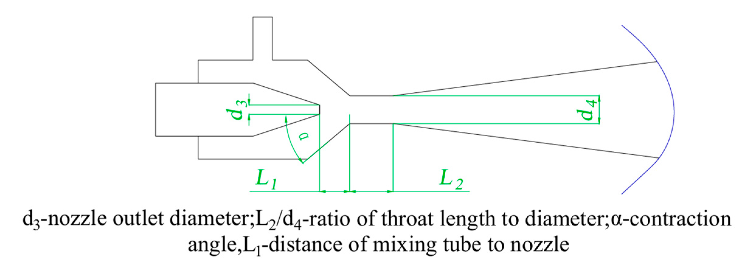
Many scholars at home and abroad have carried out extensive and in-depth research on the structural characteristics of the venturi jet reactor, and in the preliminary exploration of the influence of key structural parameters on the effectiveness of the venturi jet reactor, we found the following: the nozzle distance, as a crucial factor, directly determines the initial kinetic state of the working fluid in the region of the throat; as the core component of the jet reactor, the nozzle outlet diameter significantly influences the internal pressure distribution, playing a crucial role in determining the reactor’s hydrodynamic performance. The length-to-diameter ratio of the pipe affects the flow pattern of the fluid in the mixing section; and the angle of the mixing chamber contraction section mainly regulates the kinetic properties of the ejected fluid. In summary, these structural parameters affect the performance of the venturi jet reactor, so we simulated and analyzed different distances of mixing tube to nozzle L1, nozzle outlet diameters d3, ratios of throat length to diameter L2/d4, and contraction angles α. The simulations were performed using the control variable method jet reactor for structural optimization.
4.2.1. Influence of Structural Parameters on Flow Field
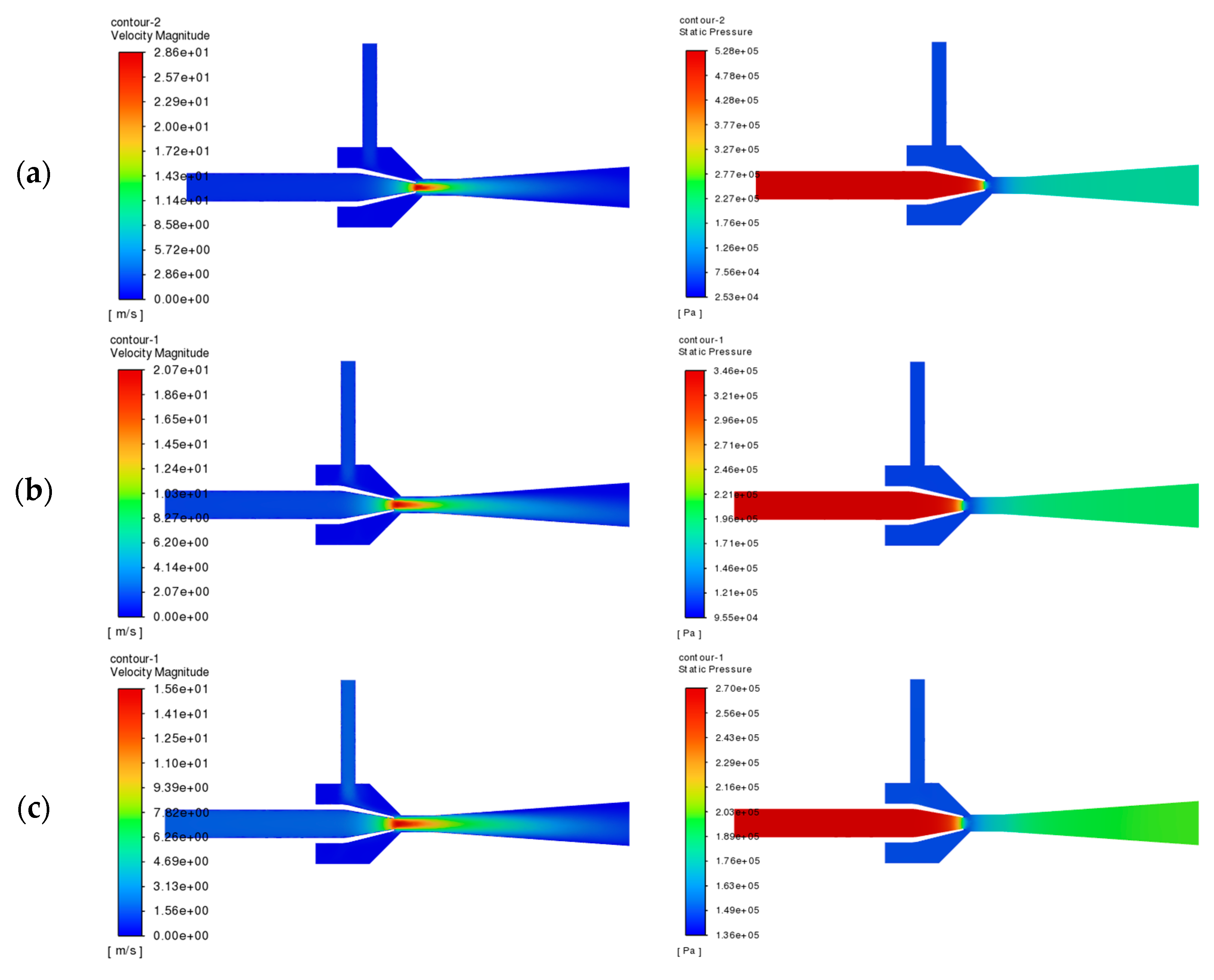
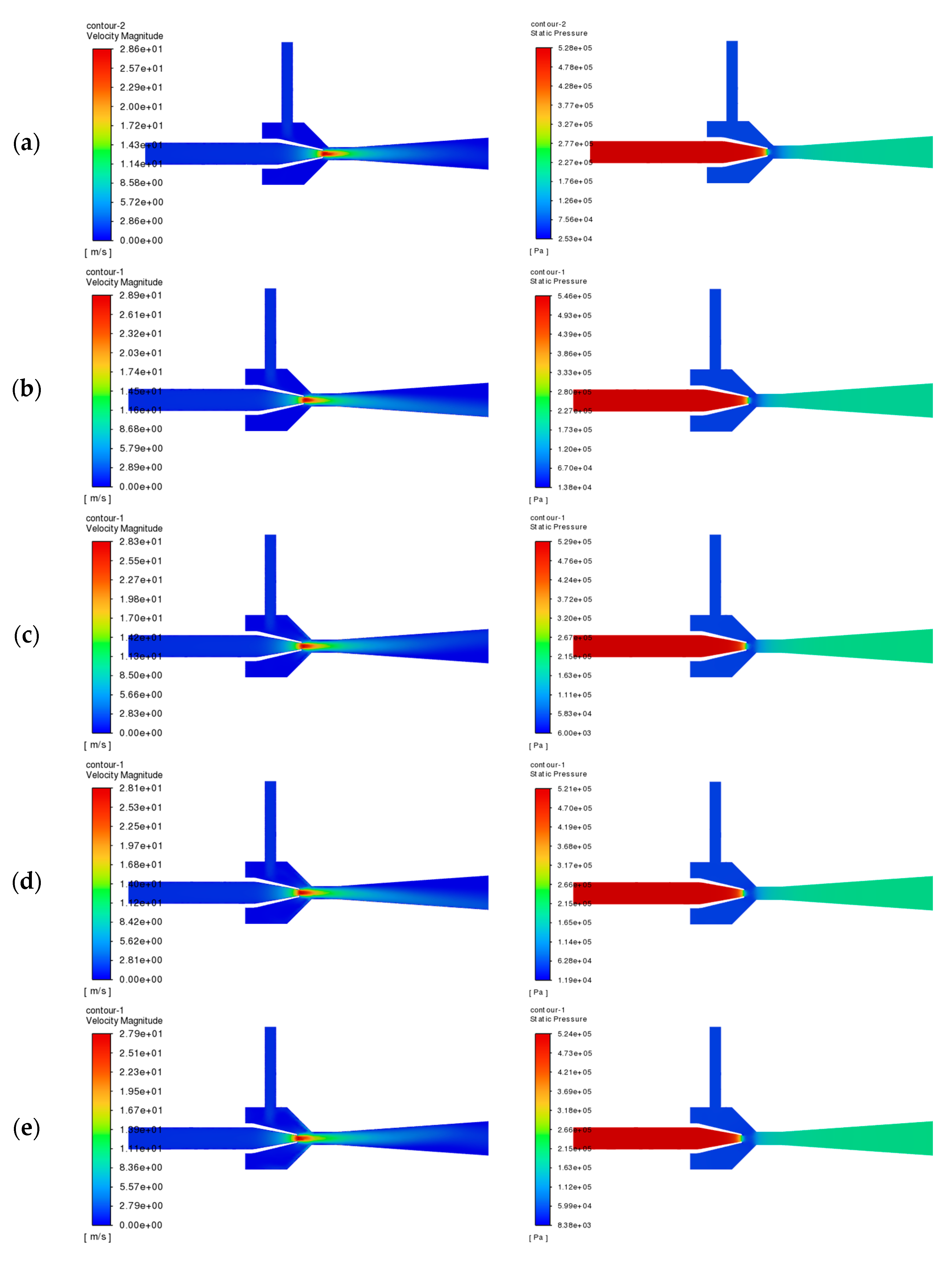
Figure 9 shows the distribution of velocity and pressure in the cross section of the jet section under different throat spacing. When the throat spacing is small, the working fluid forms a jet in the nucleus region due to the high-speed flow, which extends into the throat section, resulting in incomplete energy exchange, leading to greater energy loss. At the same time, due to the uneven velocity distribution of the two fluids at the throat, the fluid-mixing effect is not ideal. The pressure distribution pattern across different throat sections is similar, and the main difference is in the throat section. As the distance between the throat and mouth increases, the low-pressure area of the flow field mainly appears between the nozzle outlet and the throat inlet, and the range of the low-pressure area of the throat section is gradually narrowed down, and the gradient of the pressure distribution changes are not obvious.
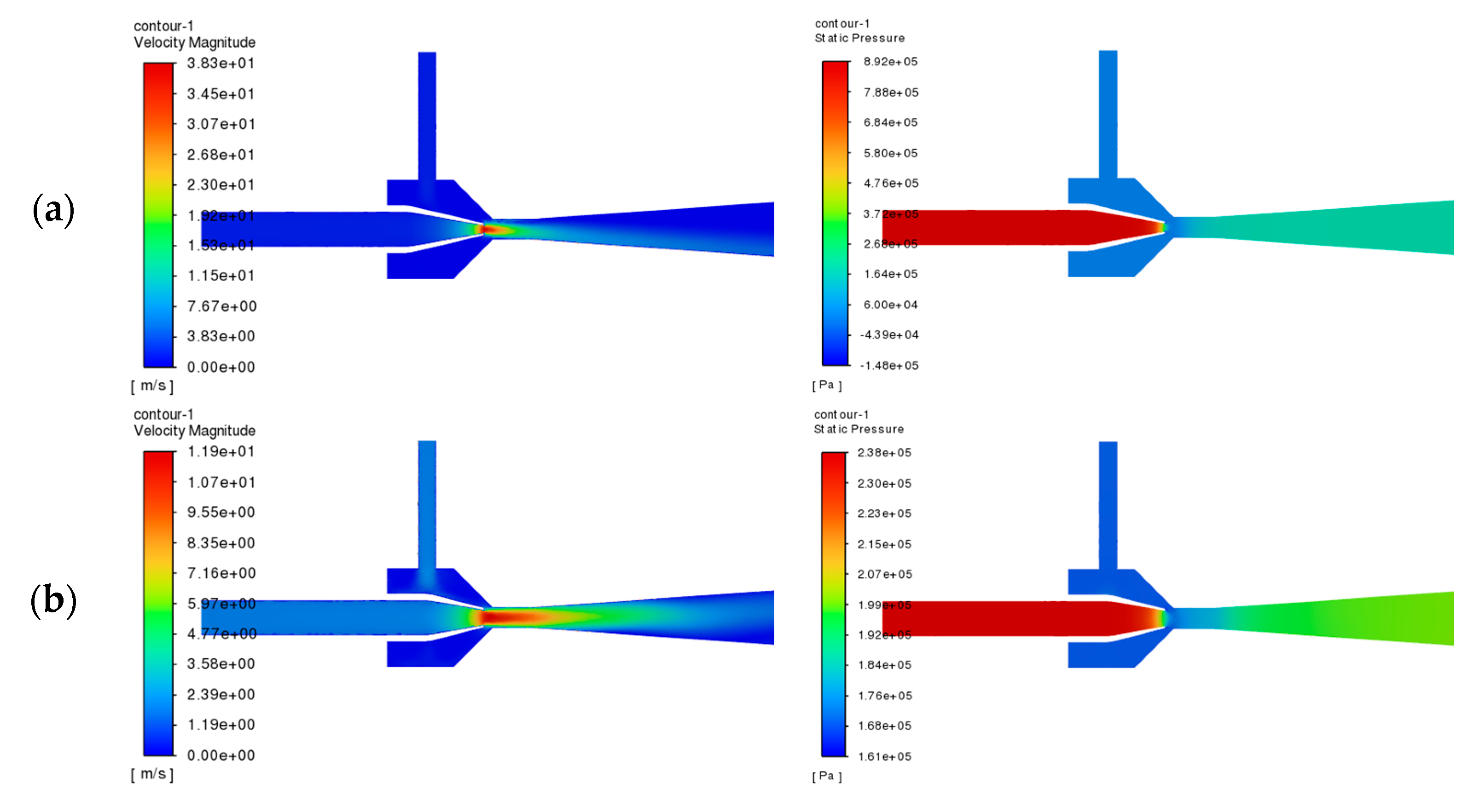
Velocity and pressure distributions were simulated for varying nozzle outlet diameters. Given the similarity of flow patterns across diameters,
Figure 10 selectively presents the flow fields for 5 mm and 9 mm cases, with the remaining data provided in
Appendix A. Analysis of
Figure 10 reveals that smaller nozzle diameters (e.g., 5 mm) generate higher jet velocities, creating stronger impingement effects that enhance fluid mixing. However, excessively small diameters may reduce mixing efficiency due to disproportionate velocity increases and shortened momentum exchange duration. Furthermore, increasing the nozzle diameter was observed to (1) decrease the injector’s peak pressure and (2) reduce the low-pressure region at the throat, suggesting improved pressure stability within the injector.
Given the minimal variation in flow field characteristics across different throat-to-diameter ratios,
Figure 11 selectively presents the velocity and pressure distributions for ratios of two, three, and four, with complete data available in
Appendix A. The results demonstrate that at ratios of two and three, the throat exit exhibits non-uniform velocity distribution with pronounced central acceleration; a ratio of four yields balanced velocity profiles, indicating complete fluid mixing; and post-throat pressure analysis reveals progressive stabilization along the pipe section, with the pressure drop completing within the throat region at a ratio of three without propagating into the diffuser.
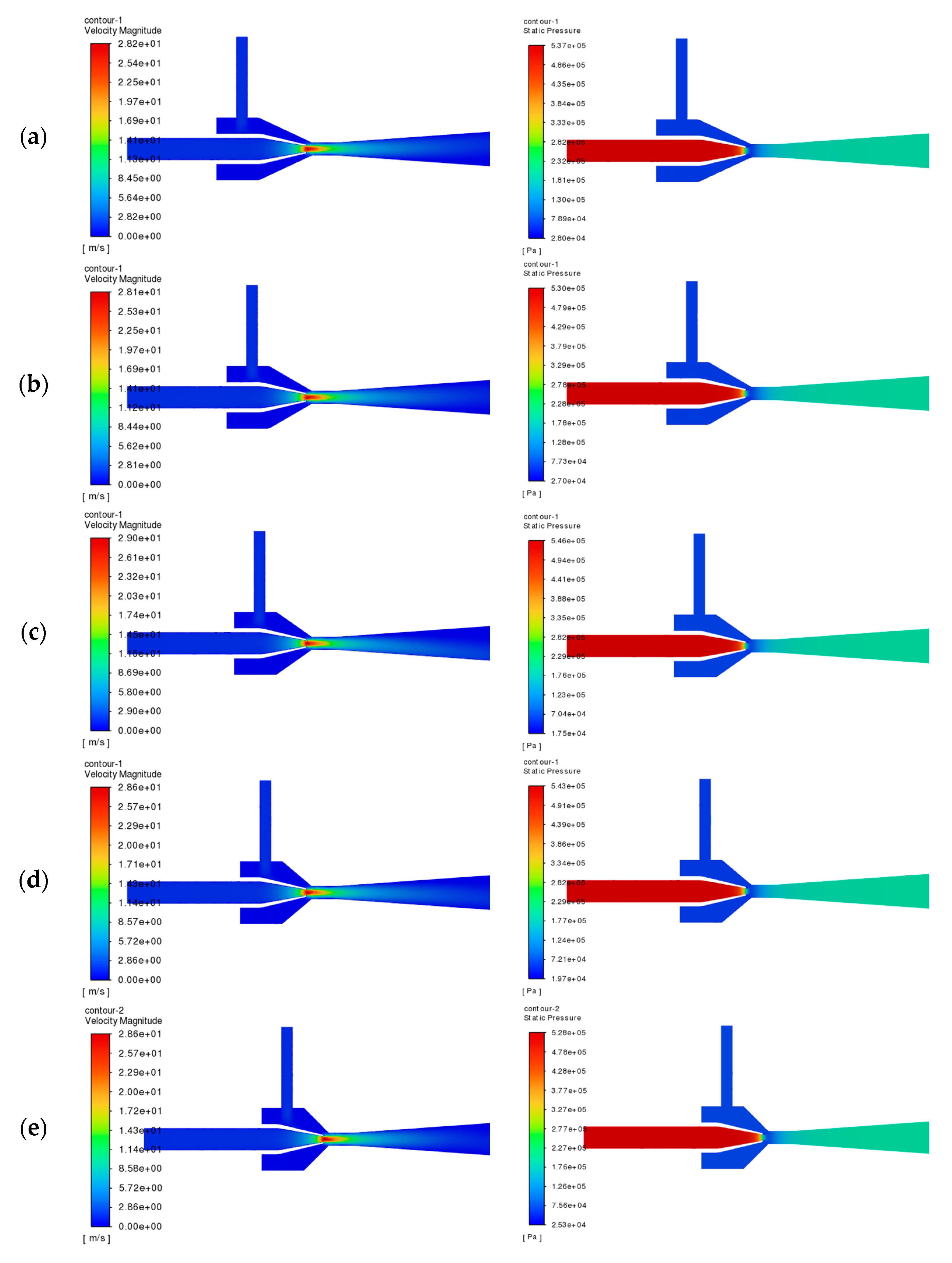
Figure 12 presents the velocity distribution and pressure cloud under different shrinkage angle conditions. It can be observed that under different contraction angles, the velocity and pressure distributions of the jet section are basically the same, and do not show obvious differences. Theoretically, with the gradual increase in the contraction angle, the path length of the ejected fluid into the throat section is shortened accordingly, which helps to reduce the along-range energy loss of the ejected fluid; however, when the contraction angle increases to a certain extent, the flow state of the ejected fluid in the corner region of the contraction section changes, and the collision and friction with the wall surface intensify, which leads to a large local resistance loss. This effect, in turn, weakens the efficiency of the injector.
Figure 13 shows the centerline pressure change in the jet section of the reactor under different parameters. According to
Figure 13, the trend of the center axis pressure change is consistent with the changes in nozzle distance, both of which are first reduced and then increased, and the pressure at the nozzle outlet reaches its lowest value. Among them, the pressure at the throat is the lowest when the nozzle distance is 13 mm, and the pumping ability of the jet reactor is the strongest at this time. As the nozzle outlet diameter decreases, the working fluid inlet pressure gradually increases; this is because the nozzle outlet diameter determines the fluid flow rate—the smaller the diameter of the nozzle outlet, the higher the nozzle outlet flow rate. This means that more pressure energy needs to be converted into kinetic energy, which puts forward higher requirements for the process pumps and pipelines, and the overall energy consumption of the system increases. As the throat diameter ratio increases, the inlet pressure of the working fluid of the injector shows an upward trend, while the lowest pressure value shown in each curve remains basically the same. This phenomenon can be attributed to the fact that when the throat diameter ratio is large, the mixing process between the working fluid and the ejected fluid is completed in advance at the front end of the throat. In this case, the long throat section leads to an increase in the resistance of the fluid along the path. The pressure changes in the center axis under different constriction angles also overlap.
4.2.2. Influence of Structural Parameters on Jet Reactor
Efficiency is an important evaluation index to define the performance of the venturi jet reactor [
17]. For the jet reactor efficiency η is calculated as follows,
where Pin1 is the inlet pressure of working fluid, MPa; Pin2 is the inlet pressure of induced fluid, MPa; Pout is the outlet pressure, MPa; Q
1 is the working fluid inlet flow rate, kg/s; and Q
2 is the injection fluid inlet flow rate, kg/s;
According to the formula of jet reactor efficiency, the efficiency of the jet reactor represents the ratio of the energy gained by the induced fluid and the energy lost by the working fluid in the process of energy exchange between the two fluids, which represents the energy utilization rate of the jet reactor, and to a certain extent reflects the performance of the jet reactor.
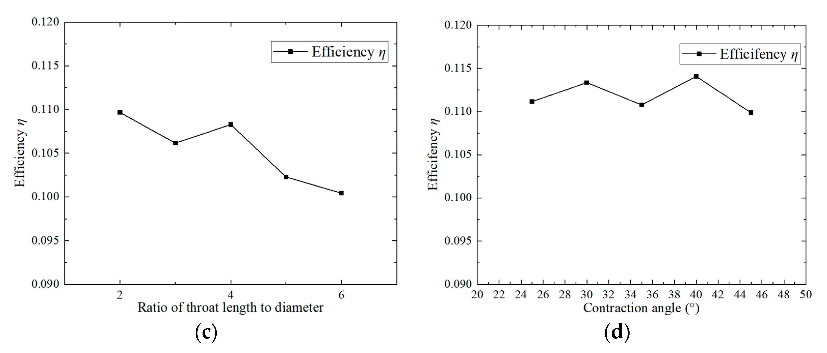
Figure 14 shows the efficiency curve of the jet reactor under different parameters; the overall efficiency of the jet reactor increases with the increase in the throat–nozzle pitch. The efficiency of the jet reactor changed significantly when the nozzle pitch increased from 7 mm to 9 mm, increasing by 10.57% after changing the size of the nozzle pitch. The efficiency of the jet reactor remained unchanged when the nozzle pitch continued to increase within the study range. With the increase in the nozzle outlet diameter of the jet reactor, efficiency gradually increases—the jet reactor outlet diameter is larger, the velocity of the working fluid jet is smaller, and the mixing process with the ejected fluid is relatively smooth, avoiding the dramatic fluctuations in the jet caused by the significant energy loss, thus ensuring that the jet reactor has high operating efficiency. The curve shows that the efficiency of the jet reactor is the highest when the throat diameter ratio is four, and then the efficiency of the jet reactor decreases with the increase in the throat diameter ratio. According to the previous analysis, when the throat diameter ratio is set to four, the distribution of velocity and pressure fields in the jet reactor shows good stability, and the mixing effect between the working fluid and the induced fluid is closer to ideal. The excess throat length leads to an increase in the flow resistance of the mixed fluid, so the efficiency of the jet reactor decreases. The efficiency of the jet reactor fluctuates up and down with the increase in the contraction angle.
4.2.3. Influence of Structure Parameters on Mixing Effect of Jet Reactor
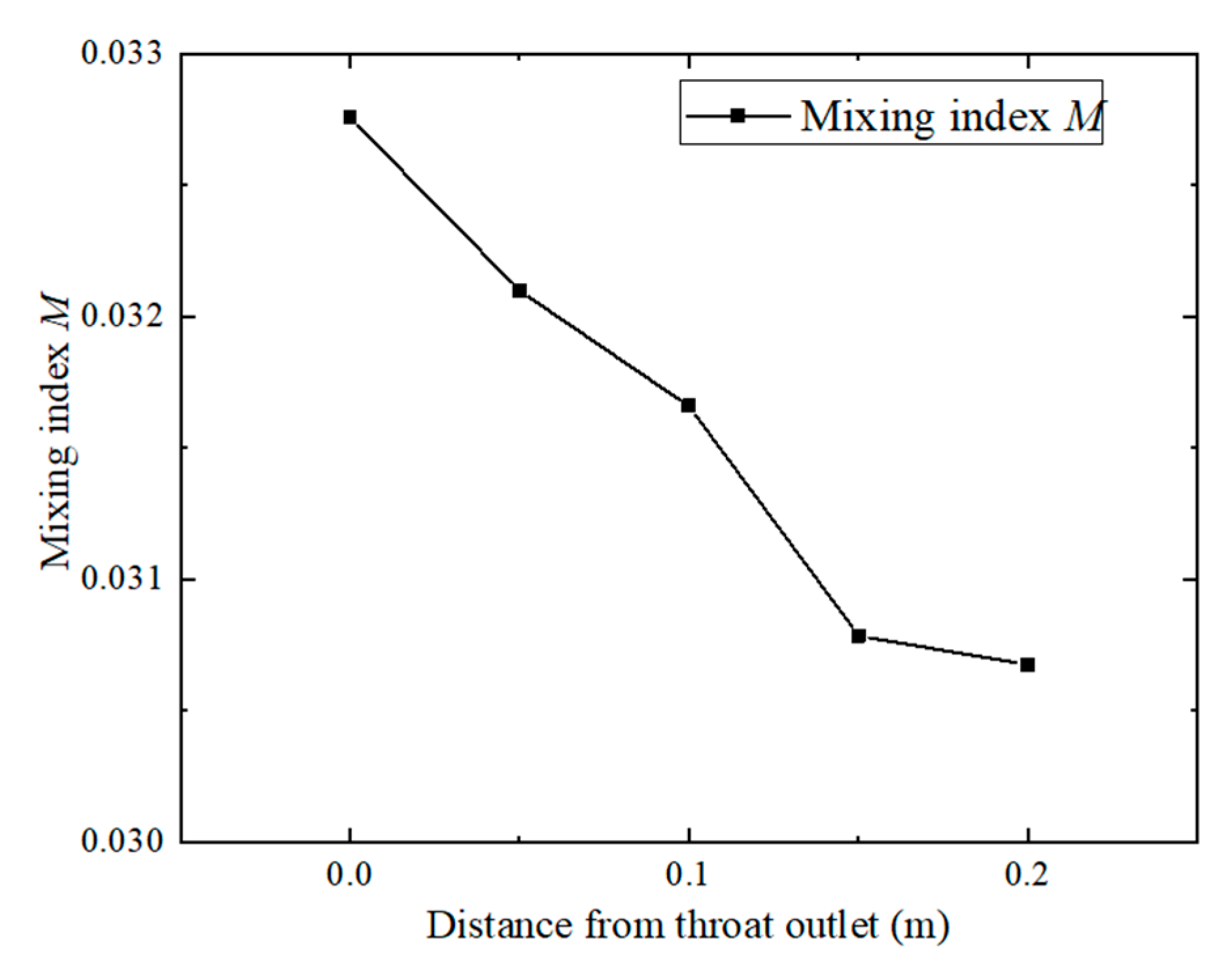
Mixing index is an important index for evaluating the mixing effect of a venturi jet reactor. Two fluids are mixed under the action of the jet and subsequently react. The mixing effect within the jet reactor is crucial, as the mixing section is the main zone for fluid mixing. By analyzing the exit cross section of the ejected fluid from the mixing section, i.e., the mass fraction of urea, the introduction of the mixing index M is introduced. The mixing index M is defined based on the standard deviation of the urea mass fraction across the cross section. The value of M indicates the degree of uniformity of fluid mixing: the smaller the M value, the more uniform the mixing. The formula for calculating the mixing index is as follows.
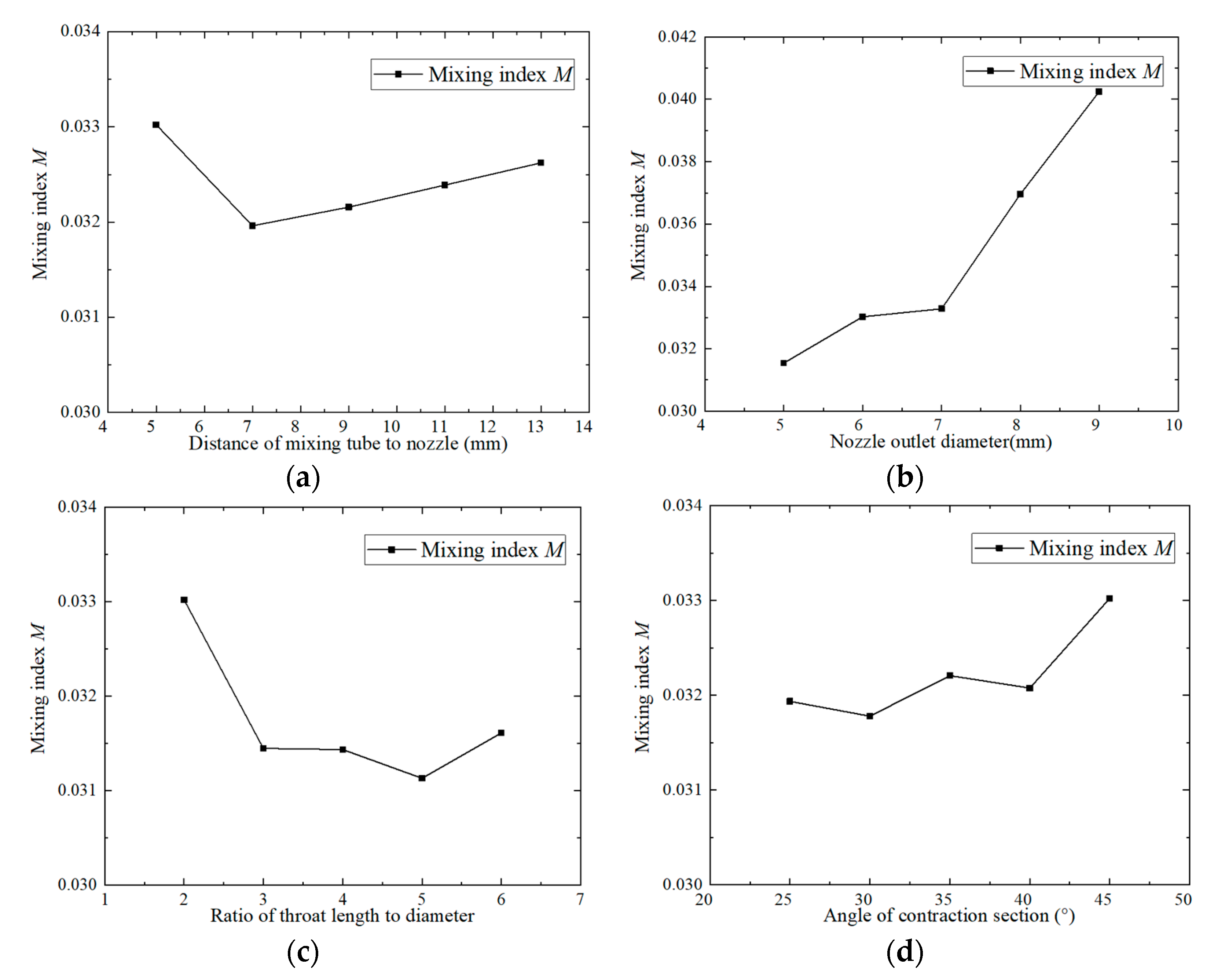
Figure 15 shows the mixing index curve of the throat outlet section of the jet reactor under different parameters. According to
Figure 15, it can be seen that the mixing index M decreases and then increases with the increase in the throat–nozzle pitch, and that the mixing index is the smallest and the mixing effect the best when the throat–nozzle pitch is 7 mm. An in-depth investigation of the specific effect of the throat–nozzle distance on the performance of the jet reactor reveals that when the throat–nozzle distance is small, the jet formed by the working fluid will rapidly enter the mixing section. At this time, due to the relatively small contact area between the two fluids, the energy exchange process between them is relatively short, resulting in a poor mixing effect of the jet reactor. With the gradual increase in the throat spacing, the working fluid and the ejected fluid have a wider area for energy exchange before entering the mixing section, the contact time between the two fluids can be extended, so the ejected fluid can obtain more energy. At the same time, the resistance in the mixing process is also reduced accordingly. In addition, the free flow beam of the working fluid is fully expanded in the process, and the flow state tends to be uniform, thus reducing the energy loss of the jet reactor and improving the efficiency of the equipment. However, when the throat–nozzle distance is too large, but when the throat–nozzle distance is too large, the nozzle outlet is too far away from the throat inlet, and the jet formed by the working fluid loses part of its energy before entering the throat, which leads to a decrease in the efficiency of the jet reactor.
The mixing index M increases with the increase in the nozzle outlet diameter, and the mixing effect gradually worsens. This indicates that the increase in nozzle outlet diameter reduces the mixing effect of the two fluids. Further analysis of the impact of the nozzle outlet diameter reveals that when the nozzle diameter is too large, the working fluid flows more smoothly, and the two streams of fluid in the throat experience less collision and turbulence. As a result, energy and momentum exchange is not complete and mixing is insufficient. From the curve, it can be seen that when the nozzle outlet diameter is larger than 7 mm, the mixing index M increases dramatically, and the mixing effect decreases sharply.
With the increase in the throat diameter ratio, the mixing index M first decreases and then increases. There is a significant decrease in the mixing index between throat diameter rations of two and three, reaching its minimum at a ratio of five, where the mixing effect of the venturi jet reactor is at its best. Further increasing the throat diameter ratio leads to a deterioration in the mixing effect. This is because, under the action of the working fluid, the ejection of fluid is sucked into the throat section and mixed, and the flow becomes more uniform, the total pressure reduction and velocity equalization are largely completed within the throat. In the diffusion section of the entrance, the velocity distribution becomes more uniform, reducing energy loss, making this throat diameter ratio the most optimal. When the throat diameter ratio is small, mixing is not completed before entering the diffusion section, so the flow is uneven and the mixing effect is not ideal. When the throat diameter ratio is too large, mixing is already completed in the front of the throat, and further increases in the throat diameter ratio will not improve the mixing effect, but will increase the resistance along the way, reducing the performance of the jet reactor, and at the same time, causing a waste of resources, increasing the cost of equipment manufacturing.
From the curve, it can be seen that as the contraction angle increases, the mixing index shows an upward trend, indicating that the mixing effect gradually worsens. When the contraction angle is increased from 40° to 45°, the mixing effect is significantly reduced. When the contraction angle of 30°, the mixing effect is the best. In the contraction section, the pilot fluid undergoes mixing due to pressure differences, and when the contraction angle is small and the section is long, the velocity change of the pilot fluid is small, the fluid flow is relatively smooth, and the mixing of the two streams of fluid is smoother, and the mixing is closer to ideal. With the increase in the contraction angle, the velocity change of the ejected fluid increases, the flow is more violent and, due to the loss of part of the energy of the ejected fluid, the mixing effect decreases. On the other hand, the increase in the contraction angle expands the low-pressure zone formed by the working fluid jet, which is favorable to the inhalation of the ejected fluid.
In summary, the influence of each parameter on the performance of the jet reactor is multifaceted, and there is a complex interaction between them. Therefore, in practical application, these parameters need to be selected and adjusted reasonably according to the specific needs and conditions in order to achieve the optimal performance of the jet reactor.
The optimal structural parameters were determined based on the analysis results, and the optimized throat–orifice distance of the jet section was 9 mm, the nozzle outlet diameter was 7 mm, the throat-to-diameter ratio was 4, and the constriction angle was 30°.
The structure optimized venturi jet reactor is remodeled, the results of the simulation are analyzed, and the velocity and pressure distribution of the optimized jet section is shown in
Figure 16. It can be seen that the velocity and pressure distribution of the mixed fluid through the throat section is uniform, indicating that the mixing effect of the two fluids is better, and the efficiency of the optimized venturi jet reactor is calculated to be 0.1720. The value before the structural optimization was 0.1098, which is an increase of 56.65% The mixing index is 0.0322, and the value before the structural optimization was 0.0330, which is an increase of 2.42% in the mixing effect. The calculation formula is as follows:
Among them, M1 is the pre-optimization mixing index, M2 is the post-optimization mixing index, η1 is the pre-optimization efficiency, η2 is the post-optimization efficiency, ε1 is the mixing effect improvement rate, and ε2 is the efficiency improvement rate.
