Abstract
During the cooling phase of injection molding, the conformal cooling channel system optimizes the uniformity of mold temperature, diminishes warping deformation, and contributes substantially to heightened product precision. The injection molding process involves complex process parameters that may result in uneven cooling between components, leading to prolonged cycle times, increased shrinkage depth, and warping deformation of the plastic parts. These manifestations negatively impact the surface quality and structural strength of the final product. This article combined theoretical algorithms with finite element simulation (CAE) methods to optimize complex injection molding processes. Firstly, the characteristics of six different types of materials were examined. Melt temperature, mold opening time, injection time, holding time, holding pressure, and mold temperature were chosen as optimization variables. Meanwhile, the warpage deformation and shrinkage depth of the formed sample were selected as optimization objectives. Secondly, an L27 orthogonal experimental design (OED) was established, and the signal-to-noise ratio was processed. The entropy weight method (EWE) was used to calculate the weights of the total warpage deformation and shrinkage depth, thereby obtaining the grey correlation degree. The influence of process parameters on quality indicators was analyzed using grey relational analysis (GRA) to calculate the range. A second-order polynomial regression model was established using response surface methodology (RSM) to investigate the effects of six factors on the warpage deformation and shrinkage depth of injection molded parts. Finally, a comprehensive comparison was made on the impact of various optimization methods and models on the forming parameters. Analyze according to different optimization principles to obtain the corresponding optimal process parameters. The research results indicate that under the principle of prioritizing warpage deformation, the effectiveness ranking of the three optimization analyses is RSM > OED > GRA. The minimum deformation rate is 0.1592 mm, which is 27.37% lower than before optimization. Under the principle of prioritizing indentation depth, the effectiveness ranking of the three optimization analyses is OED > GRA > RSM. The minimum depth of shrinkage is 0.0312 mm, which is 47.21% lower than before optimization. This discovery provides strong support for the optimal combination of process parameters suitable for production and processing.
1. Introduction
Injection molding (IM) injects completely melted plastic material into a mold cavity under high pressure at a specific temperature and obtains molded products after holding, cooling, and demolding [1,2]. Injection molding has been widely used in plastic molding technology, which can shape plastic products with complex shapes and structures, produce products with high dimensional accuracy, and has the advantages of a short molding cycle and low production cost [3]. The injection molding process starts with plastic particles entering the barrel and being converted into molten material through heating, compression, and other processes. Next, axial pressure is applied to the injection molding machine screw to hold and cool the mold [4,5]. Finally, the ejection mechanism ejects the plastic part to obtain the plastic product. The general mold opening time accounts for 15%, the injection molding time accounts for 5%, the holding time accounts for 10%, and the cooling time accounts for 70%, as shown in Figure 1 [6,7]. The temperature range of the molten material injected during the plastic molding process is 200 to 300 °C. To remove plastic parts from the mold, they must be cooled to temperatures of 60 and 80 °C, which takes up most of the molding cooling cycle. Excessive cooling time and uneven cooling can lead to deformation and warping. The cooling effect of injection molds significantly impacts the quality and productivity of products. Reducing the cooling time will improve production efficiency. To achieve the optimal cooling temperature, the temperature distribution of the mold needs to be uniform [8,9].
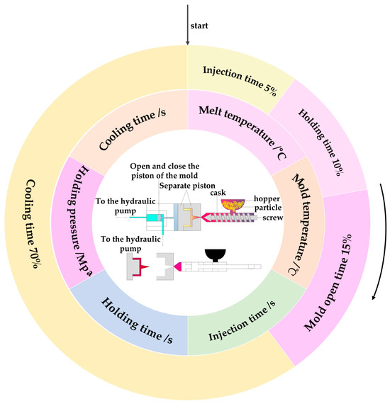
Figure 1.
Injection molding process and main stages.
The purpose of designing cooling channels in molds is to reduce the temperature of the injected material. Conventional cooling channels consist of straight-drilled channels, which have limitations as they cannot provide the best cooling effect due to the complex shape of the plastic part, which restricts the channel’s ability to fit the mold cavity’s contour at equal distances. As a result, conventional cooling channels lead to uneven cooling between components, causing issues such as prolonged cycle time, warping, and scrap rates [10]. On the other hand, conformal cooling channels (CCCs) [11,12,13] offer a solution to this problem by achieving more uniform and efficient cooling of products, as shown in Figure 2. This technology refers to a cooling water channel whose contour changes with the variation of the plastic cavity, effectively solving the problem of unequal distance between the conventional water channel and the cavity surface [14,15,16]. By maximizing heat transfer in injection molding [17,18,19], conformal cooling channels significantly enhance product quality [20,21,22,23].
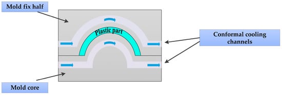
Figure 2.
Conformal cooling channels.
The frequent occurrence of many defects during the injection molding process makes injection molding very difficult. The typical injection molding defects mainly include warping deformation, shrinkage marks, weld marks, bubbles, short shots, and burrs. Various factors, such as raw materials, mold structure, and injection molding equipment, can cause injection molding defects. In addition, differences in the composition of injection molded parts and molding process parameters can also lead to uneven shrinkage of plastic parts [24,25]. Especially for some complex plastic parts, it mainly relies on the experience of injection molding engineers. However, over time, the production quality of plastic parts has yet to be guaranteed, which limits the development of complex plastic products in the mold industry. To prevent problems such as warping, shrinkage marks, and uneven shrinkage, Zhai et al. [26] proposed analyzing the optimal combination of molding parameters through Taguchi grey correlation theory. They used six optimization algorithms and inverse deformation design (IDD) to reduce volume shrinkage and warping deformation. The results showed that the warping deformation of the plastic part (polycarbonate) was reduced, and the quality of the product was improved. Marinset et al. [27] evaluated the effect of injection parameters on bending and shrinkage using Taguchi’s method and analysis of variance (ANOVA) with a polymeric copolymer and an acrylic butadiene styrene copolymer. The results indicate that the holding pressure and holding time significantly impact the warpage. Huang and Tai [28] demonstrated that the most significant factor affecting warpage during injection molding is holding pressure, followed by mold temperature, melt temperature, and holding time.
Meanwhile, the interaction between mold temperature and melt temperature is also an essential factor affecting the quality of plastic part forming. Ozcelik, B. and Eerzurunlu, T. [29] studied the effects of various process parameters on the quality of plastic parts using analysis of variance (ANOVA), artificial neural networks (ANN), and genetic algorithms (GA). The results indicate that the holding pressure is the most significant factor affecting warpage deformation. Youngjae Ryu et al. [30] validated the optimal combination of the Taguchi method and RSM using Glass Fiber Reinforced Polyamide 6 to minimize process factors and levels of shrinkage and warpage.
Ozcelik, B. [31] conducted a comparative study on the effects of melt temperature, holding pressure, and injection pressure on the mechanical properties of products with and without weld marks using polypropylene material. The Taguchi method was used to calculate plug specimens’ maximum tensile load, elongation at break, and impact strength. Experiments have shown that injection pressure has a more significant impact on the maximum tensile load and elongation at the break of specimens than melt temperature, which is the main factor affecting impact strength. Kitayama S. et al. [32] used polyacetal resin to determine the optimal process parameters in PIM through radial basis function sequential approximation optimization, to achieve high product quality and productivity. Subsequently, Kitayama et al. [33] used liquid crystal polymer and employed sequential approximation optimization (SAO) using radial basis function (RBF) networks to determine the optimal injection speed and pressure distribution through a small number of simulations, thereby improving product quality. Wang Qingwu [34] used Polyformaldehyde to analyze the relationship between key process parameters and optimization objectives in micro injection molded small modulus plastics through a second-order response surface model. Kitayama S. et al. [35] used Acrylonitrile Butadiene styrene for sequential approximation optimization in rapid thermal cycling using radial basis function networks to determine the optimal process parameters for improving product surface quality. Feng, Q. et al. [36] used acrylonitrile butadiene styrene/polyamide for data analysis through variance analysis and signal-to-noise ratio, and obtained the quality characteristics of plastic products, including warpage, welds, and clamping force, through simulation experiments. Hakimian, E. [37] studied the effects of process molding parameters and their interactions on the warpage and shrinkage of injection molded micro gears using three different types of thermoplastic materials (PC/ABS, PPE/PS, and POM) through the Taguchi method. Fu [38] optimized the process using the warpage defect of dual material products, where the melt temperature and holding pressure significantly impact the warpage defect. As the melt temperature and holding pressure increase, the warpage is improved.
Researchers utilize finite element analysis software to simulate injection-molded products and analyze their defects, such as shrinkage depth and warping deformation [39,40]. They explore the influence of different injection molding process parameters on defects through relevant experiments. By finding the optimal combination of molding process parameters, they aim to obtain the best process plan, reduce defects, improve product production quality, and shorten development cycles [41,42,43,44]. In recent years, computer-aided engineering (CAE) technology has rapidly developed [45,46], becoming a commonly used method in modern manufacturing engineering. The integration of advanced technologies such as computer-aided design (CAD) and computer-aided manufacturing (CAM) has laid the foundation for intelligent manufacturing. The application of response surface methodology (RSM) to injection molding can effectively reduce random errors generated in experiments and improve the accuracy of design schemes [47,48].
Based on the results mentioned above, the first step of this study involves designing the geometric structure of the conformal cooling water channel for the printer shell to evaluate its impact on the cooling performance of the injection mold being studied. The study also combines theoretical algorithms and CAE methods to optimize and research the injection molding process. Subsequently, the warpage deformation and shrinkage depth of the formed sample were selected as optimization objectives. Secondly, an L27 orthogonal experimental design (ODE) was established, and the signal-to-noise ratio was processed. The entropy weight method (EWE) was used to calculate the weights of the total warpage deformation and shrinkage depth, thereby obtaining the grey correlation degree. The influence of process parameters on quality indicators was analyzed using grey relational analysis (GRA) to calculate the range. A second-order polynomial regression model is established using Response Surface Methodology (RSM) to optimize and solve the model. Design Expert is used to analyze the experimental design data of RSM and explore the optimal combination of molding process parameters. Finally, a comprehensive comparison was made on the impact of various optimization methods and models on the forming parameters. Moldflow 2023 is an injection moulding and compression moulding plastic simulation software developed by Autodesk, mainly used to optimise parts, moulds, and process design to improve product quality and reduce production defects. Design Expert 13 is a professional experimental design (DOE) and response surface analysis software developed by Stat-Ease Inc. (United States). This article uses the Moldflow 2023 version and the Design Expert 13 version, respectively.
According to previous reference descriptions, the existing cooling channel structure of injection molds is simple and cannot meet the processing and production of complex injection molded parts. This article uses orthogonal experimental design, grey relational analysis, and response surface methodology to optimize six forming process parameters of a complex structured conformal cooling channel for multi-objective optimization. Finally, the characteristics of different optimization methods under different principal priorities were discovered, providing a theoretical basis and technical support for the process optimization of complex structure injection molds.
2. Materials and Methodologies
This section details experimental methods. To fulfill the study’s objectives, computer-aided engineering (CAE) technology, design of experiments (DOE), grey relational analysis (GRA), and response surface methodology (RSM) were used to optimize the target parameters in stages. Figure 3 illustrates the flowchart of the experimental procedure methodology.
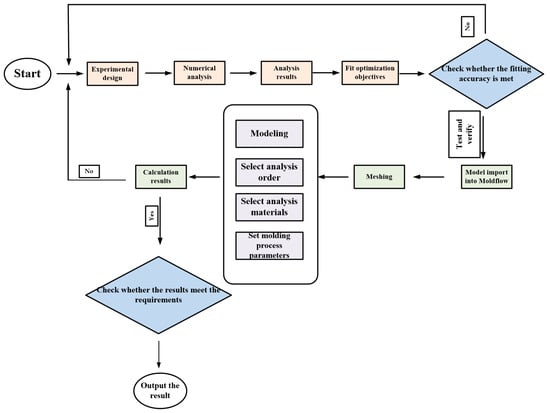
Figure 3.
Flowchart of the experimental methodology.
2.1. Creation of Plastic Model and Conformal Cooling Channel
The plastic part has a complex geometric shape with thin-walled and thick-walled areas, which makes it difficult to achieve uniform cooling during the cooling process. The product was a printer drawer case shell, with dimensions and shape as displayed in Figure 4, created using SolidWorks 2023 software to construct a plastic model. The dimensions of the part were 62 mm (L) × 49 mm (W) × 10 mm (H). Import the injection molded part model into Moldflow 2023 software and use the software to simulate and analyze the plastic part model. The materials are PP, PP + GF20%, PP + GF30% and PP + GF40%. The material manufacturer is A Schulman GMBH (Germany), and the material brand is POLYFLAM RIPP 3625 CS1. Table 1 shows the characteristics of four materials. Many curved pipes are used in the conformal cooling channel to better fit the surface of the plastic part. Therefore, a circular section is selected as the cross-sectional area of the conformal cooling channel, and the diameter of the conformal cooling channel was chosen as 10 mm, as shown in Figure 5. To improve the accuracy of subsequent analysis, the plastic parts were imported into Moldflow software to generate a double-layer mesh. The grid size is set to 2.5 mm. The total number of grid elements in the plastic component is 821,825, the total number of grid elements in the flow channel is 199,572, and the total number of grid elements in the mould is 2,126,359.
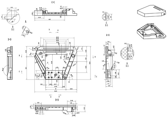
Figure 4.
Injection parts structure diagram.

Table 1.
Material characteristics.
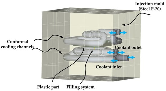
Figure 5.
Design of the conformal cooling channel system.
2.2. Experimental Method
When the warpage deformation and volume shrinkage rate of plastic parts are small, it indicates an improvement in the quality of plastic parts. This belongs to the desirable small characteristic, and the signal-to-noise ratio expression is shown in Equation (1) [26].
where S/N represents the signal-to-noise ratio, n is the number of repeated experiments, and xi is the result of the ith experiment.
Before conducting grey relational analysis, it is necessary to normalize the data of the two target objects, the total amount of mold warping deformation and the volume shrinkage rate. This is because not only are their dimensions and units different, but there are also significant differences in the range of their numerical variations. To ensure the equivalence and orderliness of the data, normalization processing must be carried out as shown in Equation (2) [26].
where yi is the normalized value; i represents the number of experiments, i = 1, 2, 3, …, 27; yimax and yimin are the maximum and minimum values in the original data, respectively.
Based on the processed data series, the grey correlation coefficient can be calculated as shown in Equation (3) [26].
where represents the normalized ideal value of the data corresponding to the i-th experiment, represents the resolution coefficient, ranges from 0 to 1, and takes a value of 0.5.
The response surface methodology replaces the response surface by fitting a global approximation of the output variables through a finite experimental design of a set of sample points within a specified design space [49,50]. In practical optimization design, response surface methodology can be applied to determine the relationship between response objectives and design variables, as well as optimization schemes, to achieve the optimal combination of the objective function. Before constructing a response surface approximation model, it is essential to clearly define the relationship between the design variables and the analysis objectives. An appropriate function form should be selected to describe the relationship between the current design variables and the analysis objectives. The response surface optimization method is currently applicable for optimization experiments involving 2–5 factors. The Box Behnken Design (BBD) design method involves three levels for each factor, which are encoded as (−1, 0, 1). The design table is arranged with 0 as the center point, and +1 and −1 are the high and low values corresponding to the cubic point, respectively [51]. The schematic diagram of the BBD experimental design is shown in Figure 6.
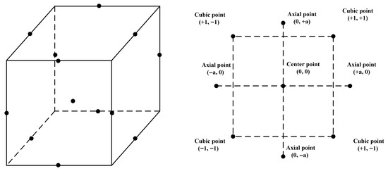
Figure 6.
BBD Experimental Design Diagram.
Response Surface Methodology (RSM) is an optimization technique proposed by Box that combines experimental design and mathematical modeling to measure the response of a system to one or more variables [52,53,54,55]. It uses a quadratic polynomial model to verify the complex unknown function relationship between factors and results within the region. It obtains the optimal values of each factor to get the prediction model. This optimization method has been widely applied in machinery, materials, and environmental fields. According to the Weierstrass polynomial best approximation theorem, the general form of the predictive polynomial Equation (4) [50] for the system response Y and the design variable x is:
where Y represents the response target values (warpage deformation, shrinkage depth, and cooling time), Xi and Xj are the independent variables (i, j = 1, 2, 3, …, n), β0, βi, βii, βij, and ε are the regression constant coefficients, linear coefficients, second-order coefficients, interaction coefficients, and statistical error, respectively.
The uneven shrinkage of general plastic parts can result in uneven internal stress within the plastic parts. If the internal stress exceeds the material’s strength limit, the plastic parts will warp and deform. Excessive warping deformation can cause difficulties in demolding the product, resulting in large dimensional deviations and low molding quality, which makes it challenging to meet the molding requirements in terms of both quality and appearance. In general, the deformation of plastic parts is optimized based on product wall thickness, material, cooling system, and injection molding process parameters to minimize significant warping deformation during the injection molding process. When there are many factors in an experiment, it is necessary to conduct a screening experiment to select a few essential factors as the research object from the numerous factors. This type of experiment can usually be undertaken using response surface methodology. Drew response surfaces and contour plots using statistical testing to predict reactions or optimize processes, demonstrating the correlation between factors and response values, and generated data using a fitted model.
3. Results and Discussion
3.1. Comparison of Different Cooling Channels System Designs
Figure 7 shows the warpage deformation, shrinkage depth, and volume shrinkage of four engineering thermoplastic materials. Through a comparative evaluation of unfilled and glass fiber-reinforced polypropylene (PP) systems, it was found that adding 40% glass fiber reduced PP warpage by 55.85%, shrinkage depth by 73.77%, and shrinkage rate by 58.28%. This may be because fibers restrict the fluidity of polymer chains, enhance thermal conductivity, and reduce residual stress. These findings provide guidance for material selection in subsequent precision injection molding applications.
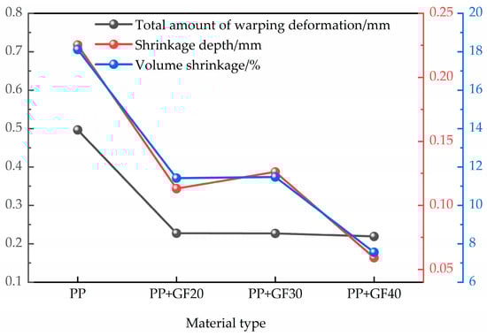
Figure 7.
Performance analysis results of different types of materials.
3.2. Orthogonal Experimental Design Results
The conclusion drawn from reading some of the literature [26,56]. The six molding process parameters, namely melt temperature (A), injection time (B), mold opening time (C), holding time (D), holding pressure (E), and mold temperature (F), have the most significant impact on complex injection molded parts. Therefore, this factor was selected as the experimental parameter.
The research factors for the injection molding process include melt temperature (A), injection time (B), mold opening time (C), holding time (D), holding pressure (E), and mold temperature (F), as shown in Table 2. Selecting the total amount of warpage deformation and volume shrinkage rate as optimization objectives, a 6-factor 3-level orthogonal experimental factor table was designed, and 27 sets of injection molding process parameter simulation experiments were conducted. The results of the shrinkage depth and the total amount of warpage deformation are shown in Table 3.
Table 2.
Orthogonal test factor level table.
Table 3.
Orthogonal experimental design results.
From the range results calculated in Table 3, the order of the influence of these six factors on the warpage deformation and volume shrinkage rate from small to large is: F < B < E < D < A < C.
The effects of various parameters on shrinkage depth and warping deformation at different factor levels are shown in Figure 8. From the figure, it can be seen that the combination of molding parameters A1-B1-C3-D1-E3-F3, using the OED method, has the smallest warpage deformation and shrinkage depth. When A1 is the melt temperature (220 °C), B1 is the mold opening time (3 s), C3 is the injection time (2 s), D1 is the holding time (10 s), E3 is the holding pressure (100 MPa), and F3 is the mold temperature (80 °C). The minimum warpage deformation is 0.1597 mm, a decrease of 26.61% compared to the initial value. The minimum shrinkage depth is 0.0312 mm, a reduction of 47.21% compared to the initial value.
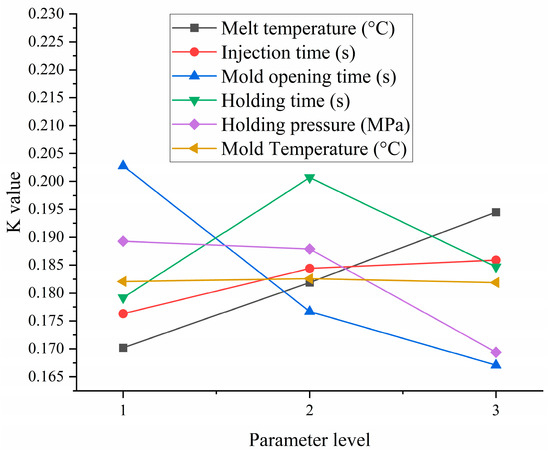
Figure 8.
Performance analysis results of different types of materials.
3.3. Entropy Weight Method Grey Correlation Results
The total warpage deformation of the plastic part affects the tolerance value of the molding, thereby influencing the fit of the product. The volume shrinkage rate determines the surface quality. This article combines entropy weight analysis and grey relational analysis to establish weight coefficients based on entropy values. The higher the entropy, the smaller the variability, and the lower the weight coefficient. The steps of this method are summarized as follows:
Construct the decision matrix for determining the body mass index results from Table 2 as shown in Equation (5) [57].
where, m is the number of experiments (m = 27), n is the experimental index (n = 2).
Further regularize the decision matrix as shown in Equation (6) [57].
where is the regularization result of the j-th test indicator in the i-th experiment.
Calculate the entropy value by normalizing the data as shown in Equation (7) [57].
where J is the experimental index (j = 2), i is the number of experiments (i = 27), and m is the number of experiments (m = 27).
Calculate the weight coefficients using Equation (8) [57].
where, J is the experimental index (j = 2), n is the number of experiments (n = 27).
After obtaining the weight coefficients through the above calculation, the grey correlation degree is calculated as shown in Equation (9).
where indicates a more consistent impact of the factor on the target object.
Substitute the results of determining the shrinkage depth and total amount of warping deformation in Table 3 into equations for calculation, and obtain the weight and grey correlation degree of the total amount of warping deformation and volume shrinkage rate as shown in Table 4. The weights of warping deformation and shrinkage index obtained are 44% and 56%, respectively.
Table 4.
The data for calculating the grey correlation degree.
According to Table 5, the larger the range value of the grey correlation degree, the greater the influence of parameters on the grey correlation degree. The order of influence of each parameter on the grey correlation degree, from largest to smallest, is Mold opening time, holding pressure, melt temperature, holding time, injection time, and Mold Temperature. Figure 9 shows the trend of the mean gray correlation degree of parameters at different levels. In the data processing stage, the observation of small feature function is used, and the higher the gray correlation value of the parameter level, the more optimal the parameter is. Therefore, according to Figure 9, the optimal solution obtained using the GRA method is A1B3C3D3E1, with a melt temperature of 220 °C, an injection time of 5 s, a mold opening time of 2 s, a holding time of 14 s, a holding pressure of 100 MPa, and a mold temperature of 60 °C. The minimum warpage deformation is 0.1594 mm, a decrease of 26.75% compared to the initial value. The minimum indentation depth is 0.0316 mm, a decrease of 46.53% compared to the initial value.
Table 5.
Range calculation of the grey correlation degree.
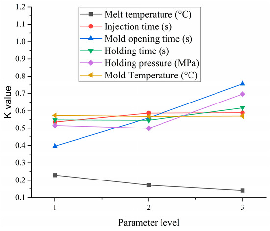
Figure 9.
The average grey correlation degree of parameters at different levels.
3.4. Analysis of Response Surface Experiment Results
The BBD experimental design was used to optimize the injection molding process parameters, with the product wall thickness, material, cooling system, and other aspects remaining unchanged. Melt temperature (A), mold opening time (B), injection time (C), holding time (D), holding pressure (E), and mold temperature (F) were selected as factors, with plastic part warpage deformation and shrinkage depth as optimization objectives. The response surface experimental design method optimizes the model, with each factor taking three levels. A 3-level and 6-factor DOE-1 table was designed, as indicated in Table 6. Based on the results of single-factor experiments, Design-Expert software was used to optimize the Box-Behnken design. An L54 orthogonal array was used to establish a quadratic polynomial response surface model, and the optimal values of the responses and corresponding factor values were calculated. The experimental data are displayed in Table 7.
Table 6.
Design an experiment of a factor level table.
Table 7.
Response surface optimization, experimental design and results.
The experimental data from the response surface methodology were processed using Design-Expert software (Table 7) to investigate the effects of melt temperature, mold temperature, holding time, and holding pressure on warpage deformation and shrinkage depth.
Within the selected process parameter range, Design Expert was used to optimize and solve the problem, with the minimum warpage deformation as the optimization objective. The optimal combination of predicted process parameters is shown in Table 8. The average errors between the predicted minimum warpage deformation and shrinkage depth of the product and the actual numerical simulation values are 3.18% and 8.6%, respectively, confirming the accuracy of the response surface model numerical simulation. The optimal combination of molding process parameters is suitable for production and processing.
Table 8.
Optimum process parameters and validation.
3.5. Comparison of Different Optimization Methods
Figure 10a shows the warpage deformation results analyzed using different optimization methods. From the figure, it can be seen that the RSM method performs the best, with significantly lower warpage deformation than the original method. The GRA and OED methods have similar effects and are both better than the original values. Under the principle of prioritizing warping deformation, the effectiveness ranking of the three optimization analyses is RSM > OED > GRA. The minimum deformation rate is 0.1592 mm, which is 27.37% lower than before optimization. Figure 10b shows the results of analyzing the depth of shrinkage using different optimization methods. From the figure, it can be seen that the OED method performs the best, followed by the GRA method, but it is still significantly better than the original method. Under the principle of prioritizing indentation depth, the effectiveness ranking of the three optimization analyses is OED > GRA > RSM. The minimum shrinkage depth is 0.0312 mm, which is 47.21% lower than before optimization. This discovery provides strong support for the optimal combination of process parameters suitable for production and processing.
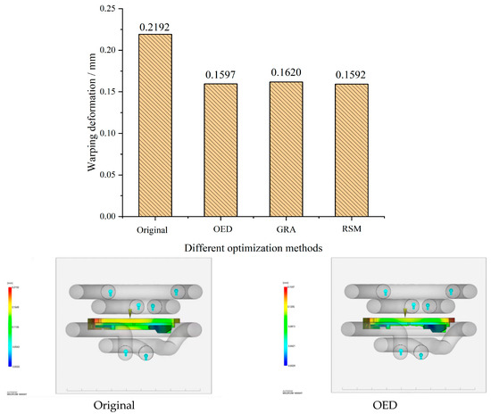
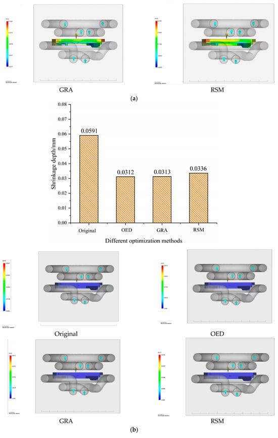
Figure 10.
Optimize simulation results (a) Analysis of warpage deformation using different optimization methods; (b) Analysis of warpage deformation using different optimization methods.
4. Conclusions
The injection mold with the conformal cooling channel (CCC) can improve the uniformity of mold temperature, reduce warping deformation, and significantly improve product accuracy. This article designs the geometric structure of the conformal cooling water channel for the printer shell, evaluates its impact on the cooling performance of the studied injection mold, and combines theoretical algorithms and CAE methods to carry out injection molding process optimization and research. The conclusions are as follows:
- The combination of molding parameters A1-B1-C3-D1-E3-F3, using the OED method, has the smallest warpage deformation and shrinkage depth. When A1 is the melt temperature (220 °C), B1 is the mold opening time (3 s), C3 is the injection time (2 s), D1 is the holding time (10 s), E3 is the holding pressure (100 MPa), and F3 is the mold temperature (80 °C). The minimum warpage deformation is 0.1597 mm, a decrease of 26.61% compared to the initial value. The minimum indentation depth is 0.0312 mm, a reduction of 47.21% compared to the initial value.
- The optimal solution obtained using the GRA method is A1B3C3D3E1, with a melt temperature of 220 °C, an injection time of 5 s, a mold opening time of 2 s, a holding time of 14 s, a holding pressure of 100 MPa, and a mold temperature of 60 °C. The minimum warpage deformation is 0.1594 mm, a decrease of 26.75% compared to the initial value. The minimum indentation depth is 0.0316 mm, a decrease of 46.53% compared to the initial value.
- The average errors between the predicted minimum warpage deformation and shrinkage depth of the product and the actual numerical simulation values are 3.18% and 8.6%, respectively, confirming the accuracy of the response surface model numerical simulation. The optimal combination of molding process parameters is suitable for production and processing.
- Under the principle of prioritizing warpage deformation, the effectiveness ranking of the three optimization analyses is RSM > OED > GRA. The minimum deformation rate is 0.1592 mm, which is 27.37% lower than before optimization. Under the principle of prioritizing indentation depth, the effectiveness ranking of the three optimization analyses is OED > GRA > RSM. The minimum depth of shrinkage is 0.0312 mm, which is 47.21% lower than before optimization.
Author Contributions
Conceptualization, M.Z. and Z.T.; methodology, M.Z. and Z.T.; software, M.Z. and Z.T.; validation, M.Z. and Z.T.; formal analysis, M.Z. and Z.T.; investigation, M.Z. and Z.T.; resources, M.Z. and Z.T.; data curation, M.Z. and Z.T.; writing—original draft preparation, Z.T.; writing—review M.Z. and Z.T.; visualization, M.Z. and Z.T.; supervision, Z.T.; project administration, M.Z.; funding acquisition, M.Z. and Z.T. All authors have read and agreed to the published version of the manuscript.
Funding
This research was funded by the 2023 Anhui Province Youth Teacher Training Action Project, grant number JNFX2023134, and the Science Research Program Projects of Universities of Anhui Province, grant number 2024AH051862.
Data Availability Statement
The raw data supporting the conclusions of this article will be made available by the authors on request.
Acknowledgments
The authors acknowledge the support of the Anhui Provincial Ministry of Education, Tongling Polytechnic, and Jiangsu University.
Conflicts of Interest
The authors declare no conflicts of interest.
Correction Statement
This article has been republished with a minor correction to the Funding statement. This change does not affect the scientific content of the article.
References
- Silva, H.M. A review of the design optimization of conformal cooling channels in injection molds. Int. J. Adv. Manuf. Technol. 2025, 138, 2653–2671. [Google Scholar] [CrossRef]
- Kanbur, B.B.; Suping, S.; Duan, F. Design and optimization of conformal cooling channels for injection molding: A review. Int. J. Adv. Manuf. Technol. 2020, 106, 3253–3271. [Google Scholar] [CrossRef]
- Zhao, M.; Tang, Z. Finite Element Simulation of Injection Mold Design Integrating Different Structures of Conformal Cooling Channels. Processes 2025, 13, 234. [Google Scholar] [CrossRef]
- Liu, F.; Pang, J.; Xu, Z. Multi-Objective Optimization of Injection Molding Process Parameters for Moderately Thick Plane Lens Based on PSO-BPNN, OMOPSO, and TOPSIS. Processes 2024, 12, 36. [Google Scholar] [CrossRef]
- Gaspar-Cunha, A.; Melo, J.; Marques, T.; Pontes, A. A Review on Injection Molding: Conformal Cooling Channels, Modelling, Surrogate Models and Multi-Objective Optimization. Polymers 2025, 17, 919. [Google Scholar] [CrossRef]
- Wang, Y.; Lee, C. Design and Optimization of Conformal Cooling Channels for Increasing Cooling Efficiency in Injection Molding. Appl. Sci. 2023, 13, 7437. [Google Scholar] [CrossRef]
- Silva, H.M.; Noversa, J.T.; Fernandes, L.; Rodrigues, H.L.; Pontes, A.J. Design, simulation and optimization of conformal cooling channels in injection molds: A review. Int. J. Adv. Manuf. Technol. 2022, 120, 4291–4305. [Google Scholar] [CrossRef]
- Wang, J.; Xuan, J.; Ni, Y. Automatic design of conformal cooling channels of injection mold based on lotus root model. Int. J. Adv. Manuf. Technol. 2023, 125, 1879–1892. [Google Scholar] [CrossRef]
- Park, H.S.; Dang, X.P. Optimization of conformal cooling channels with array of baffles for plastic injection mold. Int. J. Precis. Eng. Manuf. 2010, 11, 879–890. [Google Scholar] [CrossRef]
- Peixoto, C.; Valentim, P.T.; Sousa, P.C.; Dias, D.; Araújo, C.; Pereira, D.; Machado, C.F.; Pontes, A.J.; Santos, H.; Cruz, S. Injection molding of high-precision optical lenses: A review. Precis. Eng. 2022, 76, 29–51. [Google Scholar] [CrossRef]
- Zheng, Z.; Zhang, H.; Wang, G.; Qian, Y. Finite Element Analysis on the Injection Molding and Productivity of Conformal Cooling Channel. J. Shanghai Jiaotong Univ. 2021, 16, 231–235. [Google Scholar] [CrossRef]
- Kuo, C.-C.; Qiu, S.-X.; Lee, G.-Y.; Zhou, J.; He, H.-Q. Characterizations of polymer injection molding tools with conformal cooling channels fabricated by direct and indirect rapid tooling technologies. Int. J. Adv. Manuf. Technol. 2021, 117, 343–360. [Google Scholar] [CrossRef]
- Chung, C.Y. Integrated Optimum Layout of Conformal Cooling Channels and Optimal Injection Molding Process Parameters for Optical Lenses. Appl. Sci. 2019, 9, 4341. [Google Scholar] [CrossRef]
- Feng, S.C.; Kamat, A.M.; Pei, Y.T. Design and fabrication of conformal cooling channels in molds: Review and progress updates. Int. J. Heat Mass Transf. 2021, 171, 121082. [Google Scholar] [CrossRef]
- Brooks, H.; Brigden, K. Design of conformal cooling layers with self-supporting lattices for additively manufactured tooling. Addit. Manuf. 2016, 11, 16–22. [Google Scholar] [CrossRef]
- Arman, S.; Lazoglu, I. A comprehensive review of injection mold cooling by using conformal cooling channels and thermally enhanced molds. Int. J. Adv. Manuf. Technol. 2023, 127, 2035–2106. [Google Scholar] [CrossRef]
- Rocha, S.B.; Zhiltsova, T.; Neto, V.; Oliveira, M.S. Optimization to assist design and analysis of temperature control strategies for injection molding-a review. Materials 2022, 15, 4048. [Google Scholar] [CrossRef]
- Torres-Albe, A.; Mercado-Colmenero, J.M.; Diaz-Perete, D.; Martin-Doñate, C. A new conformal cooling design procedure for injection molding based on temperature clusters and multidimensional discrete models. Polymers 2020, 12, 154. [Google Scholar] [CrossRef]
- Saifullah, A.B.M.; Masood, S.H.; Sbarski, I. Thermal-structural analysis of bi-metallic conformal cooling for injection moulds. Int. J. Adv. Manuf. Technol. 2012, 62, 123–133. [Google Scholar] [CrossRef]
- Rahim, S.Z.A.; Sharif, S.; Zain, A.M.; Nasir, S.M.; Saad, R.M. Improving the quality and productivity of molded parts with a new design of conformal cooling channels for the injection molding process. Adv. Polym. Technol. 2016, 35, 21524. [Google Scholar] [CrossRef]
- Vojnová, E. The benefits of a conforming cooling systems the molds in injection moulding process. Procedia Eng. 2016, 149, 535–543. [Google Scholar] [CrossRef]
- Wei, Z.; Wu, J.; Shi, N.; Li, L. Review of conformal cooling system design and additive manufacturing for injection molds. Math. Biosci. Eng. 2020, 17, 5414–5431. [Google Scholar] [CrossRef]
- Shinde, M.S.; Ashtanker, K.M. Additive manufacturing-assisted conformal cooling channels in mold manufacturing processes. Adv. Mech. Eng. 2017, 9, 1–14. [Google Scholar] [CrossRef]
- Alvarado-Iniesta, A.; Cuate, O.; Schütze, O. Multi-objective and many objective design of plastic injection molding process. Int. J. Adv. Manuf. Technol. 2019, 102, 3165–3180. [Google Scholar] [CrossRef]
- Gao, H.; Zhang, Y.; Fu, Y.; Mao, T.; Zhou, H.; Li, D. Process parameters optimization using a novel classification model for plastic injection molding. Int. J. Adv. Manuf. Technol. 2018, 94, 357–370. [Google Scholar] [CrossRef]
- Zhai, H.; Li, X.; Xiong, X.; Zhu, W.; Li, C.; Wang, Y.; Chang, Y. A method combining optimization algorithm and inverse-deformation design for improving the injection quality of box-shaped parts. Int. J. Adv. Manuf. Technol. 2024, 130, 1901–1924. [Google Scholar] [CrossRef]
- Marins, N.H.; de Mello, F.B.; Silva, R.M.E.; Ogliari, F.A. Statistical Approach to Analyze the Warpage, Shrinkage and Mechanical Strength of Injection Molded Parts. Int. Polym. Process. 2016, 31, 376–384. [Google Scholar] [CrossRef]
- Huang, M.-C.; Tai, C.-C. The effective factors in the warpage problem of an injection-molded part with a thin shell feature. J. Mater. Process. Technol. 2001, 110, 1–9. [Google Scholar] [CrossRef]
- Ozcelik, B.; Erzurumlu, T. Comparison of the warpage optimization in the plastic injection molding using ANOVA, neural network model and genetic algorithm. J. Mater. Process. Technol. 2006, 171, 437–445. [Google Scholar] [CrossRef]
- Ryu, Y.; Sohn, J.S.; Yun, C.-S.; Cha, S.W. Shrinkage and Warpage Minimization of Glass-Fiber-Reinforced Polyamide 6 Parts by Microcellular Foam Injection Molding. Polymers 2020, 12, 889. [Google Scholar] [CrossRef] [PubMed]
- Ozcelik, B. Optimization of injection parameters for mechanical properties of specimens with weld line of polypropylene using Taguchi method. Int. Commun. Heat Mass Transf. 2011, 38, 1067–1072. [Google Scholar] [CrossRef]
- Kitayama, S.; Yokoyama, M.; Takano, M.; Aiba, S. Multi-objective optimization of variable packing pressure profile and process parameters in plastic injection molding for minimizing warpage and cycle time. Int. J. Adv. Manuf. Technol. 2017, 92, 3991–3999. [Google Scholar] [CrossRef]
- Kitayama, S.; Hashimoto, S.; Takano, M.; Yamazaki, Y.; Kubo, Y.; Aiba, S. Multi-objective optimization for minimizing weldline and cycle time using variable injection velocity and variable pressure profile in plastic injection molding. Int. J. Adv. Manuf. Technol. 2020, 107, 3351–3361. [Google Scholar] [CrossRef]
- Wu, W.; He, X.; Li, B.; Shan, Z. An Effective Shrinkage Control Method for Tooth Profile Accuracy Improvement of Micro-Injection-Molded Small-Module Plastic Gears. Polymers 2022, 14, 3114. [Google Scholar] [CrossRef]
- Kitayama, S.; Tsurita, S.; Takano, M.; Yamazaki, Y.; Kubo, Y.; Aiba, S. Multi-objective process parameters optimization in rapid heat cycle molding incorporating variable packing pressure profile for improving weldline, clamping force, and cycle time. Int. J. Adv. Manuf. Technol. 2020, 120, 3669–3681. [Google Scholar] [CrossRef]
- Feng, Q.; Liu, L.; Zhou, X. Automated multi-objective optimization for thin-walled plastic products using Taguchi, ANOVA, and hybrid ANN-MOGA. Int. J. Adv. Manuf. Technol. 2020, 106, 559–575. [Google Scholar] [CrossRef]
- Hakimian, E.; Sulong, A.B. Analysis of warpage and shrinkage properties of injection-molded micro gears polymer composites using numerical simulations assisted by the Taguchi method. Mater. Des. 2012, 42, 62–71. [Google Scholar] [CrossRef]
- Fu, S.J. Optimization of process parameters for injection molding based on taguchi technique. Adv. Mater. Res. 2018, 538, 1170–1174. [Google Scholar] [CrossRef]
- Mohan, M.; Ansari, M.N.M.; Shanks, R.A. Review on the effects of process parameters on strength, shrinkage, and warpage of injection molding plastic component. Polym. Plast. Technol. Eng. 2017, 56, 1–12. [Google Scholar] [CrossRef]
- Singh, G.; Verma, A. A Brief Review on injection moulding manufacturing process. Mater. Today 2017, 2, 1423–1433. [Google Scholar] [CrossRef]
- Gong, G.; Chen, J.C.; Guo, G. Enhancing tensile strength of injection molded fiber reinforced composites using the Taguchi-based six sigma approach. Int. J. Adv. Manuf. Technol. 2017, 91, 3385–3393. [Google Scholar] [CrossRef]
- Xu, G.; Yang, Z. Multiobjective optimization of process parameters for plastic injection molding via soft computing and grey correlation analysis. Int. J. Adv. Manuf. Technol. 2015, 78, 525–536. [Google Scholar] [CrossRef]
- Tian, M.; Gong, X.; Yin, L.; Li, H.; Ming, W.; Zhang, Z.; Chen, J. Multi-objective optimization of injection molding process parameters in two stages for multiple quality characteristics and energy efficiency using Taguchi method and NSGA-II. Int. J. Adv. Manuf. Technol. 2017, 89, 241–254. [Google Scholar] [CrossRef]
- Zhao, J.; Cheng, G.; Ruan, S.; Li, Z. Multi-objective optimization design of injection molding process parameters based on the improved efficient global optimization algorithm and non-dominated sorting-based genetic algorithm. Int. J. Adv. Manuf. Technol. 2015, 78, 1813–1826. [Google Scholar] [CrossRef]
- Huang, C.T.; Chen, X.-W.; Fu, W.W. Investigation on the Fiber Orientation Distributions and Their Influence on the Mechanical Property of the Co-Injection Molding Products. Polymers 2020, 12, 24. [Google Scholar] [CrossRef]
- Jong, W.-R.; Huang, Y.-M.; Lin, Y.-Z.; Chen, S.-C.; Chen, Y.-W. Integrating Taguchi method and artificial neural network to explore machine learning of computer aided engineering. J. Chin. Inst. Eng. 2020, 43, 346–356. [Google Scholar] [CrossRef]
- de Paiva, A.P.; Gomes, J.H.F.; Peruchi, R.S.; Leme, R.C.; Balestrassi, P.P. A multivariate robust parameter optimization approach based on principal component analysis with combined arrays. Comput. Ind. Eng. 2014, 74, 186–198. [Google Scholar] [CrossRef]
- Chen, W.-C.; Nguyen, M.-H.; Chiu, W.-H.; Chen, T.-N.; Tai, P.-H. Optimization of the plastic injection molding process using the Taguchi method, RSM, and hybrid GA-PSO. Int. J. Adv. Manuf. Technol. 2016, 83, 1873–1886. [Google Scholar] [CrossRef]
- Li, H.; Liu, K.; Zhao, D.; Wang, M.; Li, Q.; Hou, J. Multi-objective optimizations for microinjection molding process parameters of biodegradable polymer stent. Materials 2018, 11, 2322. [Google Scholar] [CrossRef]
- Chiang, K.T.; Chang, F.P. Analysis of shrinkage and warpage in an injection-molded part with a thin shell feature using the response surface methodology. Int. J. Adv. Manuf. Technol. 2007, 35, 468–479. [Google Scholar] [CrossRef]
- Chen, C.-C.; Su, P.-L.; Lin, Y.-C. Analysis and modeling of effective parameters for dimension shrinkage variation of injection molded part with thin shell feature using response surface methodology. Int. J. Adv. Manuf. Technol. 2009, 45, 1087–1095. [Google Scholar] [CrossRef]
- Tsai, K.-M.; Tang, B.-H. Determination of injection molding process window based on form accuracy of lens using response surface methodology. Int. J. Adv. Manuf. Technol. 2014, 75, 947–958. [Google Scholar] [CrossRef]
- Tsai, K.-M.; Luo, H.-J. Comparison of injection molding process windows for plastic lens established by artificial neural network and response surface methodology. Int. J. Adv. Manuf. Technol. 2015, 77, 1599–1611. [Google Scholar] [CrossRef]
- Wang, G.; Zhao, G.; Li, H.; Guan, Y. Research on optimization design of the heating/cooling channels for rapid heat cycle molding based on response surface methodology and constrained particle swarm optimization. Expert Syst. Appl. 2011, 38, 6705–6718. [Google Scholar] [CrossRef]
- Wang, G.; Zhao, G.; Guan, Y. Research on optimum heating system design for rapid thermal response mold with electric heating based on response surface methodology and particle swarm optimization. J. Appl. Polym. Sci. 2010, 119, 902–921. [Google Scholar] [CrossRef]
- Zhang, L.; Chang, T.-L.; Tsao, C.-C.; Hsieh, K.-C.; Hsu, C.-Y. Analysis and optimization of injection molding process on warpage based on Taguchi design and PSO algorithm. Int. J. Adv. Manuf. Technol. 2025, 137, 981–988. [Google Scholar] [CrossRef]
- Shen, Y.; Jiang, W.; Li, J.; Gu, T.; Yuan, M. Multi-objective optimization research on the sleeve structure parameters of the autonomous refuelling arm for oil tank trucks. Eng. Optim. 2025, 1–25. [Google Scholar] [CrossRef]


Disclaimer/Publisher’s Note: The statements, opinions and data contained in all publications are solely those of the individual author(s) and contributor(s) and not of MDPI and/or the editor(s). MDPI and/or the editor(s) disclaim responsibility for any injury to people or property resulting from any ideas, methods, instructions or products referred to in the content. |
© 2025 by the authors. Licensee MDPI, Basel, Switzerland. This article is an open access article distributed under the terms and conditions of the Creative Commons Attribution (CC BY) license (https://creativecommons.org/licenses/by/4.0/).