Abstract
In many scientific and engineering fields, such as hydrogeology, petroleum engineering, geotechnical research, and developing renewable energy solutions, fluid flow modeling in porous media is essential. In these areas, optimizing extraction techniques, forecasting environmental effects, and guaranteeing structural safety all depend on an understanding of the behavior of single-phase flows—fluids passing through connected pore spaces in rocks or soils. Darcy’s law, which results in an elliptic partial differential equation controlling the pressure field, is usually the mathematical basis for such modeling. Analytical solutions to these partial differential equations are seldom accessible due to the complexity and variability in natural porous formations, which makes the employment of numerical techniques necessary. To approximate subsurface flow solutions, traditional methods like the finite difference method, two-point flux approximation, and multi-point flux approximation have been employed extensively. Accuracy, stability, and computing economy are trade-offs for each, though. Deep learning techniques, in particular convolutional neural networks, physics-informed neural networks, and neural operators such as the Fourier neural operator, have become strong substitutes or enhancers of conventional solvers in recent years. These models have the potential to generalize across various permeability configurations and greatly speed up simulations. The purpose of this study is to examine and contrast the mentioned deep learning and numerical approaches to the problem of pressure distribution in single-phase Darcy flow, considering a 2D domain with mixed boundary conditions, localized sources, and sinks, and both homogeneous and heterogeneous permeability fields. The result of this study shows that the two-point flux approximation method is one of the best regarding computational speed and accuracy and the Fourier neural operator has potential to speed up more accurate methods like multi-point flux approximation. Different permeability field types only impacted each methods’ accuracy while computational time remained unchanged. This work aims to illustrate the advantages and disadvantages of each method and support the continuous development of effective solutions for porous medium flow problems by assessing solution accuracy and computing performance over a range of permeability situations.
1. Introduction
In subsurface engineering and environmental applications, flow in porous media—interconnected pores in rocks or soils—occurs often. Both natural (soils, aquifers, oil, or gas reservoirs) and artificial (filters, ceramics) systems contain porous media. In many disciplines, precise flow modeling is essential because fluids (such as water, hydrocarbons, etc.) are propelled through the pore network by pressure gradients [1]. For example, replicating oil or gas flow in reservoirs directs recovery tactics, while modeling groundwater flow and pollutant transport informs aquifer management and water supply planning [1]. Since subsurface cavities or variations in pore pressure can result in subsidence or collapse of foundations, porous flow modeling is also essential in geotechnical engineering [2]. Darcy flow models are also used to evaluate the long-term stability and efficiency of geothermal or carbon sequestration systems [3,4,5,6].
Numerous real-life decisions across energy, environmental, and infrastructure sectors involve porous flow models. To start with, Darcy flow simulations help engineers assess reservoir pressure responses to ensure that extraction activities remain safe and do not cause sudden instabilities in the reservoir. This is especially vital when considering the high financial stakes involved: offshore rig downtime can cost up to USD 1 million per day, while anchor-handling vessels may incur expenses of over USD 100,000 per day [7]. Furthermore, the cost of drilling a single offshore well can vary from USD 30 million to more than USD 100 million, dependent on reservoir complexity and sea depth [8]. Accurately modeling pressure fields and fluid behavior is thus not just a technical requirement but a critical economic safeguard that influences scheduling, risk mitigation, and regulatory compliance.
Hydrogeologists rely on Darcy flow models to manage aquifers by forecasting the effects of groundwater pumping, recharge strategies, and contaminant transport. These models are essential in designing sustainable water supply strategies and in remediation planning for polluted aquifers. For example, it has been demonstrated that doubling the recharge rate in some aquifers can accelerate pollutant flushing by up to three times, drastically reducing cleanup costs and timescales [9]. On the other hand, incompetent pumping can cause soil subsidence, dry up wells, and drop water tables [10]. Aquifer storage and recovery (ASR) systems, which enable temporary water storage during rainy seasons and its repurposing during dry spells, are also designed with the aid of modeling. Numerical models offer a mathematical foundation for investment planning, resource allocation, and environmental legislation.
The structural integrity of buildings, tunnels, and dams can be threatened by pressure-driven subsurface flow in civil engineering, especially in karst terrain and cracked soils. When evaluating geohazards including sinkhole formation, foundation collapse, and hydraulic structure leaks, modeling groundwater flow is essential. The economic ramifications are significant: losses from ground subsidence caused by sinkholes surpass USD 300 million per year in the United States alone [11]. Engineers can create suitable mitigation techniques like grouting or dewatering by modeling pressure distribution and locating voids under the surface [12]. Under the direction of Darcy-based simulations, these measures guarantee adherence to building safety regulations and avert expensive failures. The model is a fundamental part of geotechnical engineering and urban planning as its correctness directly affects the dependability of infrastructure.
Emerging energy technologies such as carbon capture and storage (CCS), geothermal energy extraction, and underground hydrogen storage heavily rely on porous-flow modeling to ensure both performance and safety. In CO2 sequestration projects, Darcy-based simulations predict long-term plume migration, reservoir pressurization, and caprock integrity. In saline aquifers, for example, injection costs can be as low as USD 1.31 per ton of CO2 if reservoir pressure is properly controlled [13] and plume radii can reach up to 18 km over several decades [14]. If appropriate geomechanical modeling is not used, reservoir pressures may exceed 80% of the rock’s fracture strength, which might lead to unintentional leaking [15]. Comparably, modeling contributes to economic feasibility in CO2 plume geothermal systems by calculating storage needs of 2–7 Mt CO2 per MWe, with injection prices ranging from USD 8 to USD 17 per ton [16]. These applications demonstrate the importance of porous-media simulations in the development of safe and sustainable energy systems as well as in conventional resource exploitation.
Darcy Flow Equation Darcy’s law is the traditional model for one-phase flow in a saturated porous media. The basic equation that models this process is the continuity equation, which indicates mass conservation:
Here, is porous media’s porosity, is fluid’s density, is time variable, is fluid’s velocity, indicates source and sink terms. Source is the inflow, and sink is the outflow per volume at predetermined well places.
Darcy’s law, named after the French engineer Henri Darcy, is an empirical relation that models filtering through porous media at low flow velocities . Through a series of studies, Darcy found in 1856 that the filtration velocity is proportional to both the fluid pressure gradient and gravity-induced effects [13]. More specifically, the gradient law below relates pressure and gravity forces to the volumetric flow density (henceforth referred to as flow velocity):
Here, is the permeability of the media, is the viscosity of the media, is the gravitational constant, and is the spatial coordinate in the upward vertical direction. For this project, only two-dimensional flow was considered, thus dropping the term . Furthermore, it is enforced that the fluid’s characteristics do not change over time as well as porosity, viscosity, and density parameters which remain constant. This simplifies Equations (1) and (2) to:
Adding Equation (4) into (3) and combining viscosity parameter into the permeability variable:
The derived equation is an elliptic partial differential equation (PDE) for pressure. Further in the work, homogeneous and heterogeneous permeability fields are considered. The goal is to solve Equation (5) for pressure. Afterwards, visualize the solution and use Equation (4) to model the flow of velocity directions.
Since there is typically no closed-form solution to the elliptic Darcy equation in actual heterogeneous media, numerical discretization is employed. Numerous traditional techniques have been used like finite difference method (FDM), finite volume method (FVM), two-point flux approximation (TPFA), multi-point flux approximation (MPFA), and mixed finite element method (MFEM) [17,18,19,20,21,22,23]. Details of the discretization methods using FDM, TPFA, and MPFA methods are further elaborated next.
Finite difference method (FDM) approximates derivatives on a structured grid (e.g., regular Cartesian mesh). Each grid point pressure is related to neighbors via finite differences. FDM is straightforward and efficient for simple domains, but it is limited by grid geometry: handling complex boundaries or anisotropic permeability is difficult in standard FDM.
Two-point flux approximation (TPFA). A popular discretization technique in reservoir modeling, especially in cell-centered finite-volume frameworks. In its most basic version, TPFA uses a two-point stencil to calculate the flux across a cell face, and it is entirely dependent on the pressures in the two neighboring cells. This method is favored by many commercial simulators due to its simplicity, computational efficiency, and robustness [17,18,19,20,21,22,23]. However, the accuracy of TPFA is conditional on the so-called K-orthogonality requirement: the method is only consistent when the computational grid is aligned with the principal directions of the permeability tensor and satisfies certain geometric constraints [17,18,19,20,21,22,23]. On unstructured grids or in media with anisotropic and misaligned permeability, TPFA may introduce significant errors due to its inability to accurately capture the underlying physics [17,18,19,20].
Multi-point flux approximation (MPFA) schemes were developed to overcome TPFA’s limitations on general grids. MPFA incorporates more neighboring cell pressures to estimate flux, effectively using multiple points around a face [20,21,22,23]. For example, the MPFA-O variant includes diagonal neighbor contributions, enabling it to capture flux in the presence of a full-tensor permeability on arbitrary, non-orthogonal meshes. In short, MPFA addresses TPFA’s shortcomings by adding support points to handle off-diagonal diffusion terms [20]. This comes at the cost of complexity: MPFA requires solving local linear systems for fluxes. Moreover, MPFA schemes can suffer numerical artifacts (spurious oscillations or loss of monotonicity) on highly anisotropic or skewed grids [20,21,22,23].
Other discretizations, like finite element methods (FEMs), are also common, especially with unstructured meshes, as in geological modeling. In practice, many simulators implement pressure velocity mixed FEM or weak formulations. Specialized mimetic or embedded methods exist as well. But TPFA/MPFA remain predominant in reservoir simulation due to mass conservation and locality. Accuracy, stability, and computational cost are trade-offs for each method (FDM, TPFA, MPFA, FEM, etc.). On structured grids, for instance, basic FDM/TPFA solvers can operate relatively quickly, whereas MPFA or mixed FEM handle heterogeneity better but require bigger stencils or system solutions [17]. The resultant sparse linear systems are solved using conventional linear solvers (e.g., conjugate gradient, multi-grid).
There are several software tools available to numerically solve Darcy flow problems, ranging from basic scripts to sophisticated simulations, like DarcyLite (version 2.0.1 on 27 July 2023), MRST (version 2025a), COMSOL (website: https://www.comsol.com/, accessed date: 20 June 2025), and OpenFOAM (version v2412) [24,25,26,27].
A computational toolkit called DarcyLite was created using MATLAB to make it easier to numerically simulate flow and transport events in two-dimensional porous media. A variety of finite element techniques, such as continuous Galerkin (CG), discontinuous Galerkin (DG), weak Galerkin (WG), and mixed finite element methods (MFEMs), are especially used to solve the Darcy equation. DarcyLite provides researchers, educators, and students with an approachable but potent platform by utilizing MATLAB’s versatile matrix operations and user-friendly programming environment. It is ideal for both applicable research and teaching in fields including biological transport processes, oil reservoir modeling, and groundwater flow because of its graphical user interface and modular architecture, which facilitate effective experimentation and visualization [24].
MATLAB Reservoir Simulation Toolbox (MRST) is a comprehensive, open-source toolbox (developed by SINTEF) for research in reservoir engineering [25]. MRST is written in MATLAB/Octave and includes modules for single- and multiphase flow, transport, wells, and more. It implements finite-volume schemes (TPFA, MPFA, mimetic, etc.) on general grids, upscaling tools, automatic differentiation, and linear solvers. The toolbox’s popularity is evidenced by hundreds of scientific papers using MRST. MRST is extensible and often used to develop or test new numerical methods (e.g., custom solvers or ML-based methods).
COMSOL Multiphysics is a commercial FEM-based simulation platform [26]. Its Porous Media Flow Module provides physics interfaces to solve Darcy and related equations (including unsaturated flow, conjugate flow, etc.). COMSOL allows easy coupling with other physics (heat transfer, geomechanics) and has a user-friendly GUI. Many geoscience and engineering teams use COMSOL for prototyping and multiphysics studies involving porous flow.
OpenFOAM is an open-source [27] CFD toolbox that can simulate porous-media flow by adding Darcy resistance terms in its Navier–Stokes solvers (or via specialized library modules). Users can configure a porous zone with given permeability and Forchheimer coefficients. OpenFOAM is widely used in research and industry (especially for fluid flow and thermal problems) and can handle complex 3D geometries.
Other tools include national or commercial reservoir simulators (e.g., CMG (website: https://www.cmgl.ca/solutions/software/, accessed date: 20 June 2025), Eclipse (version 2025.1)) which implement TPFA/MPFA solvers with full well-modeling, as well as specialized codes (DuMux (website: https://git.iws.uni-stuttgart.de/dumux-repositories/dumux, accessed date: 20 June 2025), FEHM (website: https://github.com/lanl/FEHM/tree/master, accessed date: 20 June 2025), etc.). The above tools (especially MRST, COMSOL, OpenFOAM) form a practical ecosystem for developing and testing new Darcy solvers and for real-world applications. The amount of already developed tools (even some commercialized ones) indicates the importance of finding the solution to Darcy flow equation.
In recent years, machine learning has been applied to porous media problems in two main directions: (i) modeling and prediction of physical properties or system responses (e.g., permeability changes, saturation levels, flow rates), and (ii) data-driven surrogate modeling of PDE solvers, where neural networks learn to approximate or solve governing flow equations. For the first category, artificial neural networks have been successfully used to capture complex physical behaviors based on experimental or simulation data. For example, the authors in [28] used a multilayer perceptron artificial neural network to model permeability reduction in carbonate rocks due to calcium sulfate precipitation during waterflooding, achieving good agreement with core flooding experiments.
In the second category, neural network designs have been formulated as PDE solvers for the porous flow problem by several researchers [23]. Convolutional neural networks (CNNs) can be trained to map between input and output fields (for example, mapping a permeability image to the pressure field). In a supervised setting, a CNN can learn the solution operator of the PDE from precomputed data. Some works have used physics constraints (making the CNN “physics-informed”) to improve generalization. For instance, in [29] the authors used a convolutional PINN architecture for two-phase Darcy flows (pore pressure and saturation). Although purely CNN-based solvers for single-phase flow are still emerging, they represent a flexible surrogate approach (CNNs are naturally suited to Cartesian grids or image-like representations of the fields).
Physics-informed neural networks (PINNs) embed the PDE into the loss function of a neural network. A neural net is trained so that it simultaneously fits boundary data and minimizes the residual of Darcy’s equation at training points. In other words, the network’s loss includes terms like Equation (5). This idea allows for a “mesh-free” solution of PDEs with no labelled training data [29]. PINNs have been applied to various flow problems. For single-phase flow, Almajid et al. [30] and others have used PINNs to learn pressure fields in heterogeneous aquifers. PINNs can handle irregular domains and parameter estimation in principle, but they may suffer from training difficulties and slow convergence.
Fourier neural operators (FNOs)/neural operators. Neural operators aim to learn the mapping from input functions (e.g., permeability field ) to output functions (solution ) in a way that generalizes across different discretizations. The Fourier neural operator applies convolution in spectral (Fourier) space as a learnable operator. Critically, the authors in [31] demonstrated the FNO on the 2D Darcy equation and achieved orders-of-magnitude speedups over traditional solvers: the FNO could predict the solution almost 1000 times faster while maintaining high accuracy. In their experiments, the FNO was more accurate and much faster than baseline CNNs or direct solvers. Thus, neural operators like FNOs provide a promising path to extremely fast surrogate PDE solvers once trained.
Generative/hybrid models (e.g., GANs). Researchers have also explored generative models to augment classical solvers. For example, the authors in [32] proposed a Simulation Enhancement GAN (SE-GAN) for reservoir simulation. In their method, a coarse-grid finite-volume simulation is first run; the GAN then takes this coarse solution plus permeability data and generates a refined fine-grid solution. This deep network is trained to map coarse results to fine results, effectively “upscaling” the solution. In numerical tests, the SE-GAN achieved significant accuracy improvements and reduced computational time compared to running a full fine-scale solver [32]. This exemplifies how deep learning can accelerate traditional simulations: instead of solving the full linear system on a fine mesh, one trains a network offline and then uses it to reconstruct fine details cheaply.
The philosophies behind these modern methods vary: GAN-type techniques enhance coarse simulations, PINNs solve the PDE directly through optimization, and CNNs and FNOs seek to substitute a learnt surrogate operator for the solver. They are all topics of ongoing study.
Overall, the accuracy and speed of Darcy solvers directly impact decisions in various application areas related to Darcy flow modeling. Faster or more accurate methods enable higher-resolution modeling and real-time risk assessment. For those reasons, the aim of this work is to create numerical solutions for the elliptic partial differential equation problem for single-phase flow in porous media and investigate their performance by comparing them with each other. The following objectives are addressed in this paper:
- Analyze numerical discretization methods to solve the provided partial differential equation.
- Analyze deep learning methods to solve the provided partial differential equation.
- Comparison of results between numerical solution methods and deep learning methods.
2. Materials and Methods
For incompressible single-phase flow in porous media, Darcy’s law states that the volumetric flux v is proportional to the pressure gradient via the permeability tensor, e.g., (with hydraulic head ). Combining Darcy’s law with mass conservation ( for steady flow) yields the elliptic PDE:
where is the permeability, is the hydraulic head, and is any source term. In general, this is a second-order elliptic equation. Since only two-dimensional grid and variable permeability are considered, the equation simplifies the one provided in (5). When varies in space (heterogeneous permeability), no closed-form (analytical) solution exists [33]. Only in the special case of constant (a homogeneous medium) does the equation reduce to the standard Laplace/Poisson equation, for which classical analytical solutions (e.g., via Green’s functions or separation of variables) are known for simple geometries. However, real subsurface fields have complex heterogeneity, with rapid changes in permeability and porosity along with multiscale nature of rock matrix, so analytic formulas are impractical. In practice, one must therefore solve the pressure equation numerically [33]. To finalize, the equation used in this paper is equal to Equation (5), where viscosity, density, and porosity are considered constant over the whole domain.
2.1. Problem and Domain Definition for Solving Darcy Flow Elliptic PDE Equation
This paper’s aim is to solve the simplified Darcy flow equation provided in (5). The parameters, initial, and boundary conditions used in each numerical scheme are given in Table 1. Domain was discretized into a uniform Cartesian grid. Discrete permeability grid was achieved by directly sampling grid cell permeability values from Gaussian distribution.

Table 1.
Problem’s parameter description.
To handle potential sharp permeability contrasts in heterogeneous fields, smoothing during the generation of the Gaussian permeability field was incorporated. Specifically, a moving average filter with a window was applied twice to the Gaussian random field, reducing noise and ensuring spatial correlation.
Paper tasks are structured in the following order:
- Domain description, permeability field generation.
- Numerical method realizations.
- Deep learning methods training.
- Visualization and comparison between methods/models.
Methods and models are evaluated using the following:
- For accuracy: mean absolute error (MAE) and mean squared error (MSE).
- For timing: training time (for deep learning models) and inference time.
Since an analytical solution was not derived, the FDM method is selected as the base for comparisons.
The used hardware and software to achieve the results presented in this paper are the following:
- Hardware
- ⚬
- Personal computer:
- ▪
- Operating system—Windows 11 Home;
- ▪
- Version—23H2;
- ▪
- Processor (CPU)—Intel(R) Core(TM) i5-9300H CPU @ 2.40 GHz;
- ▪
- System type—64-bit operating system, x64 base processor;
- ▪
- Working memory (RAM)—32 GB;
- ▪
- Video card (GPU)—NVIDIA GeForce GTX 1650.
- ⚬
- KTU AI notebook platform:
- ▪
- Operating system—Ubuntu Linux;
- ▪
- Version—24.04.2 LTS;
- ▪
- Processor (CPU)—Intel(R) Xeon(R) Gold 6438Y+ @ 4.00 GHz;
- ▪
- System type—64-bit operating system, x64 base processor;
- ▪
- Working memory (RAM)—1 TB;
- ▪
- Video card (GPU)—NVIDIA H100 NVL (2 units).
- Software
- ⚬
- MATLAB R2023b for initial realization.
- ⚬
- Python 3.11 for final realizations and deep learning. Main used packages:
- ▪
- “NumPy”;
- ▪
- “PyTorch”;
- ▪
- “NeuralOperator”.
The mixed usage of several computers and programming languages provided flexibility and faster modeling. Initial realizations were made using MATLAB and personal computers. However, after delving into deep learning, a switch to Python was eventually made: all previous realizations were ported from MATLAB to Python and improved. This enabled seamless discretization and deep learning method comparison without additional need of result converting and moving.
The usage of the KTU AI notebook aided with deep learning training times. The use of powerful GPU units made training from 10,000 to 60,000 times faster than simple training on a personal computer’s CPU. For code sharing, the GitHub repository (https://github.com/, accessed on 4 April 2025) was established.
2.2. Numerical Solution Methods of Darcy Flow Elliptic PDE Equation
Numerical approaches offer a useful and reliable substitute for analytical solutions to PDEs when they are unattainable or nonexistent, especially when dealing with spatially heterogeneous or anisotropic media. Numerical methods are becoming essential resources for resolving a variety of PDE issues in engineering and scientific settings, including fluid flow in porous media. The governing elliptic equation for single-phase flow is solved numerically by discretization techniques in this paper. In particular, the FDM, TPFA, and MPFA techniques are used.
FDM is a numerical discretization technique, which converts an ordinary differential equation (ODE) or PDE into a system of linear equations, which can then be solved utilizing matrix algebra [34]. This is achieved by means of the problems domain discretization [35]. Domain is discretized into a grid of rectangles. For elliptic PDEs, such as the Darcy flow problem, the FDM discretizes spatial derivatives at each grid point using central finite differences. In two-dimensional Cartesian coordinates with ∆x—the distance between cell centers in x axis and ∆y—the distance between cell centers in the axis, the central finite difference approximation for the Laplacian operator at a grid point is given by Equation (7) [35].
Here, is unknown pressure value. Thus, the discretized Equation (6) at each internal grid point becomes
where and represent the permeabilities at cell interfaces, often computed as harmonic means. However, to try to achieve better accuracy, other methods for permeabilities averaging can be used, such as linear average, geometric average, or k-means average [36]. Interactions of grid cells, that Equation (8) encompasses, are visualized in Figure 1. Edge grid cells have fewer neighboring cells; thus, some terms of Equation (8) are dropped.
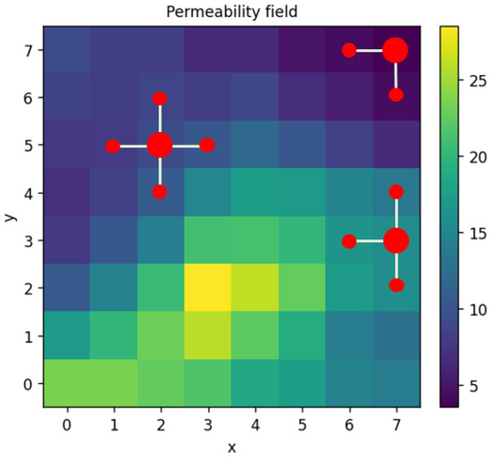
Figure 1.
Grid cell interactions visualization.
Equation (8) can be formulated for every cell of the grid and the combination of such equations forms a linear algebraic system that can be expressed in matrix form (9) as:
where is a sparse matrix, of size , where is the number of cells in and -directions, representing coefficients of pressures at neighboring points, is the vector of unknown pressures, and represents source terms. Matrix sparsity [37] is visualized in Figure 2. Each row of matrix represents a single grid cell. The resulting sparse linear system can be solved using standard linear algebra methods.
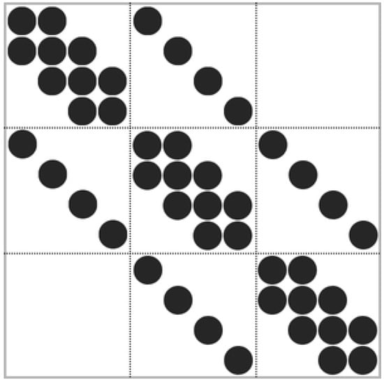
Figure 2.
Matrix sparsity visualization.
Considering TPFA or MPFA, problem domain can be discretized similarly as in the case of the FDM method. To obtain the numerical solution, the focus shifts to permeability at the interfaces of cells (see Figure 3a).
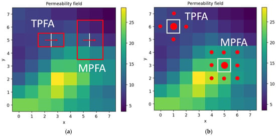
Figure 3.
(a) TPFA and MPFA permeability at grid cell interfaces (red arrow indicates an example of flow direction); (b) TPFA and MPFA grid cells interactions.
Similarly to the FDM method, and permeabilities at the interfaces of cells are often calculated using the harmonic mean method [17]. Permeabilities at the interfaces of cells in the case of the MPFA method can be calculated using the MFPA-O method. In such cases, not two grid cells’ permeability would contribute to the result as in the TPFA case, but six. This results in 9 grids cells’ permeability contribution to the pressure of a single grid cell (see Figure 3b). Such an approach may encompass more realistic fluid flow compared to FDM or TPFA, where only 5 grid cells are used (see Figure 3b) [17]. Having permeabilities at grid cell interfaces, a mass conservation equation is assembled for every grid cell. These equations can then be expressed in same matrix form (9) as with FDM.
2.3. Deep Learning Methods for Solving Darcy Flow Elliptic PDE Equation
Deep learning techniques have become strong substitutes for traditional numerical PDE solvers, particularly for challenging issues such as single-phase flow in porous media. CNNs, PINNs, and neural operators are the three deep learning methods that were concentrated on. With different designs and trade-offs, each approach provides a different technique to approximate the solution of an elliptic PDE. Each approach is briefly described, its mathematical form and network structure are outlined, and its benefits and drawbacks are discussed.
CNNs are widely used as data-driven surrogates for spatially structured PDE problems. A CNN processes input grids (e.g., a permeability or source field) through layers of convolutional filters, enabling it to capture local spatial features and heterogeneities. For example, a U-Net–style architecture (an encoder–decoder with skip connections) is often used for image-to-image regression tasks [38]. In porous-media flow, a CNN can learn the mapping from a discretized permeability field to the pressure field over the domain, acting as a parametric solution operator. CNNs can be trained purely on data (supervised regression against known solutions) or in a physics-guided way: in the “theory-guided” CNN (TgCNN) framework, the training loss includes the discretized PDE residual, improving accuracy compared to a plain CNN [39]. Visualization of simple CNN’s working scheme [40] is presented in Figure 4.
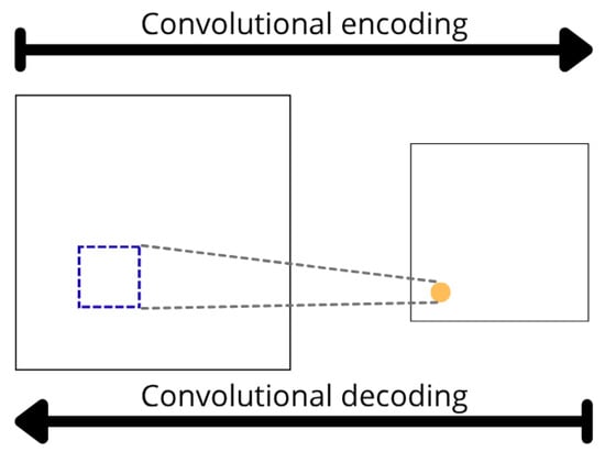
Figure 4.
Example of simple CNN structure for 2D.
The governing equation in single-phase flow is Darcy’s law and mass conservation, which for steady incompressible flow gives an elliptic PDE (5). A CNN surrogate parameterizes the solution as via its trainable weights . In purely data-driven training, one minimizes the mean squared error against labeled solutions (). In a physics-informed variant, one also enforces the PDE, e.g., by defining the residual and adding terms to the loss. Through convolutional filters (often of small spatial support, e.g., kernels), the CNN implicitly learns spatial derivatives and patterns; PICNN methods have shown that convolutional filters can approximate finite-difference derivatives to respect conservation laws [38]. Training may use additional constraints (such as boundary conditions) as needed in the loss.
For this paper, the CNN developed for solving the elliptic PDE (5) has the following structure:
- Input is discretized permeability fields on a regular grid . The dimension of input is a matrix of size ;
- Output is a predicted discretized pressure field on a regular grid . The dimension of output is the same as the input: a matrix of size ;
- A simple architecture was chosen with encoder and decoder layers all using simple kernel sizes and ReLU activation function. The network structure is represented by Figure A1 in Appendix A.
One advantage of CNN models is that CNN surrogates automatically include heterogeneity on a pixel-by-pixel basis by utilizing spatial convolution [38]. They scale well on large grids (with GPU acceleration) and provide quick inference once trained. CNNs can implicitly guarantee local continuity through convolutions and capture intricate nonlinear mappings with comparatively few parameters. To increase accuracy, they can use PDE data with physics guidance (TgCNN/PICNN) [35,39].
CNNs’ drawbacks include the fact that they frequently need huge training datasets of labeled solutions and that they might not generalize well beyond the training distribution. Since they are only data-driven models, conservation rules are not always guaranteed (until physics components are introduced). Additionally, CNN designs are restricted to a certain grid resolution and domain; retraining is necessary when the mesh or geometry is changed. Boundary circumstances can be more difficult to manage than in classical solutions since they must be handled either through the data or loss. Finally, it might be difficult to train CNNs with high precision and it is a frequent problem to adjust their depth/width to prevent over- or under-fitting.
PINNs use a neural network to represent the solution of the PDE and enforce the governing equations as part of the loss function [41]. In this approach, a feed-forward (fully connected) network approximates the pressure field over the spatial domain. The rationale is that embedding physical laws into training allows the network to learn solutions consistent with the PDE and boundary conditions, without requiring a mesh. PINNs are mesh-free and can easily incorporate complex boundary conditions or heterogeneous coefficients. They have been applied to many PDEs, including Darcy flow in porous media and coupled Stokes–Darcy systems [17,42]. Because the network is trained by minimizing the PDE residual, PINNs can also solve inverse problems (e.g., identifying ) by treating unknown parameters as trainable.
For single-phase Darcy flow, consider again the elliptic PDE (5) with appropriate boundary conditions (e.g., Dirichlet or Neumann). The PINN approximates where denotes network weights. The loss function is typically the sum of the PDE residual loss over interior collocation points and boundary loss over boundary points. For instance, define the residual:
Then, the loss might be as follows:
Here, denotes number of collocation points, denotes number of boundary points, and enforces any Dirichlet boundary values. Automatic differentiation is used to compute the derivatives in exactly from the network output. The network is trained (e.g., via Adam or L-BFGS) to minimize [41]. In practice, one chooses collocation points (e.g., randomly or on a grid) to evaluate both parts of the loss.
For this paper, the PINN used has the following structure:
- Input is spatial coordinates and . The dimension of input is of size .
- Output is a predicted pressure value for the given coordinate. The dimension of output is simply a single number.
- A simple architecture was chosen with hidden layers all using the Tanh activation function. The network is purely trained on collocation points, and no pre-labeled data is provided. So, this network is an example of unsupervised learning. The structure is represented by Figure A2 in Appendix A.
Pros of PINNs are that they strictly incorporate the PDE and boundary conditions into training, so the learned solution automatically satisfies physics constraints within the training tolerance [41]. They do not require a mesh or explicit discretization and can handle irregular domains or coupled multiphysics problems. PINNs can also assimilate data (e.g., measurements) naturally by adding data loss terms. They are flexible for inverse problems (e.g., learning unknown parameters in ) because one can augment with physical parameters.
Cons of PINNs are that training them is often computationally expensive and sensitive to network initialization and hyperparameters. PINNs can struggle with stiff or multi-scale PDEs: for example, when varies by orders of magnitude or viscosity is very small, the network may have difficulty minimizing all loss terms simultaneously [42]. Similarly, problems with sharp interfaces or discontinuities (e.g., a fracture) can cause convergence issues. The approach may converge slowly or become stuck in local minima, and it also necessitates careful selection of collocation sites and balancing of loss terms [42]. To obtain high accuracy in practice, further training techniques (such domain decomposition or loss weighting) are sometimes required.
Neural operators aim to learn the mapping (operator) from input functions (e.g., permeability fields) to output functions (e.g., pressure fields) directly [30]. Unlike a fixed CNN surrogate or a PINN solving a single PDE instance, a neural operator is trained to approximate the solution operator enabling it to handle new input functions without retraining. Two prominent neural operator architectures are deep operator networks (DeepONet) and Fourier neural operators (FNOs). Both have been shown to be highly effective for parametric PDEs, including Darcy flow [39,43].
Mathematically, we consider a family of PDEs parameterized by a function (e.g., ). DeepONet is based on the universal approximation theorem for operators. It consists of two subnetworks: a branch net that encodes the input function values at a fixed set of sensor points, and a trunk net that encodes the evaluation location. Concretely, if the input function is sampled at points , the branch net produces a feature vector from these samples. The trunk net takes a coordinate and outputs features . The DeepONet prediction is then combined, for example, by:
This network is trained on pairs of input functions and solution fields to learn the operator [43]. DeepONet can approximate nonlinear operators given relatively few training samples, but its accuracy depends on the choice of sensor points and the complexity of the function space [43].
The Fourier neural operator (FNO) takes a different approach. It learns a global convolution kernel in Fourier space. Given an input function (e.g., or initial condition) on a uniform grid, the FNO first applies a pointwise linear transform, then repeatedly applies Fourier layers. In each Fourier layer, the network computes the Fourier transform of the current feature map , multiplied by a learned filter for a limited set of low-frequency modes, and transforms back to physical space. Symbolically, one layer gives
where is the Fourier transform and is a pointwise weight matrix [26]. After several such layers, a final linear mapping produces the output . Because of the spectral convolution, the FNO efficiently captures global information and can even generalize across resolutions. It has 20 demonstrated zero-shot super-resolution (evaluating at finer grids) and is much faster at inference than traditional solvers [26].
For this paper, the FNO type operator was developed, and it has the following structure:
- Input is discretized permeability fields on a regular grid . The dimension of input is a matrix of size ;
- Output is a predicted discretized pressure fields on a regular grid . The dimension of output is the same as the input: a matrix of size ;
- A simple FNO architecture was chosen with input and output channels, hidden channels, projection channel ratio set to , and n_modes parameter set to . The FNO was initialized using “neuraloperator” package’s wrapper function FNO(). The structure is represented by Figure A3 in Appendix A.
The ability of neural operators to generalize across input functions is one of its advantages. FNO exhibited zero-shot generalization to finer grid resolutions, enabling high-fidelity super-resolution inference without retraining. Similarly, DeepONet was applied to parametric PDEs and shown to learn nonlinear operators with relatively few training samples. The network successfully predicted solutions for a wide range of input functions, even when the training set was limited to sparse sensor-point evaluations. Neural operators can rapidly forecast the solution for novel permeability fields once they have been taught. Specifically, the FNO also can conduct zero-shot super-resolution outside of the training grid and attain great accuracy [26]. These models can learn a whole solution manifold and capture intricate mappings in a single shot. Both the FNO and DeepONet have theoretical underpinnings: FNO’s global convolution performs very well in smooth PDEs, while DeepONet is supported by a universal operator approximation theorem [43]. They can take advantage of GPU acceleration and are very parallelizable.
Cons of neural operators are that their training typically requires a large dataset of input–output function pairs covering the variability in the input space. The FNO is limited to uniform (often periodic) domains since it relies on FFTs; handling complex geometries or irregular grids may require workarounds (e.g., padding) [44]. DeepONet’s performance depends on sensor placement and may require many sensors for overly complex inputs. Both methods have many hyperparameters (layers, modes, width) and can be memory-intensive. Like other deep models, they lack strict guarantees of physical constraints unless enforced by additional losses, and they may extrapolate poorly outside the training distribution.
3. Results and Discussion
The numerical results from the solution of the elliptic PDE controlling single-phase flow in porous media are shown in this section. The main objective is to assess how the pressure field behaves under various input circumstances and modeling methodologies. Analyzed are principal elements including pressure distribution, numerical method comparison, and deep learning techniques. Each component offers comprehensive numbers along with analysis of the computing performance and trends found.
3.1. Solution Domain in 2D
To start a simple permeability field, generation and domain descriptions were realized. Since parameters of the domain-like shape and grid discretization step are easily implementable, here are provided only visual results for the permeability field generation. To leave space for further research, in total seven different permeability field types were described. Five of them are deterministic and always the same: homogenous, layered, channel, checkerboard, and circular inclusion. Gaussian-type fields incorporate randomness and can be different with each run. Two different versions were realized. The only difference between them is how the generated values are post-processed: the second version has additional smoothing steps and value exponentiation to increase the scale. Visual representations are provided below (Figure 5):
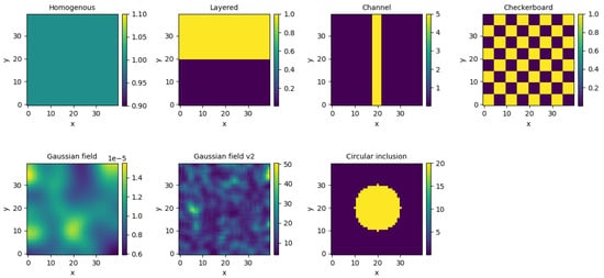
Figure 5.
Different permeability distribution on 2D domains.
For further results, the second version of Gaussian field generation type was used to create permeability field(s).
3.2. Numerical Solution
After domain descriptions, the numerical methods FDM, TPFA and MPFA were realized. Additionally, from the pressure field solution, using Equation (4), flow directions were calculated and visualized. To start off, two permeability fields were generated: homogenous and heterogeneous. Their visualization is given below (Figure 6):
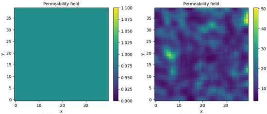
Figure 6.
Generated homogeneous (left) and heterogeneous (right) permeability fields.
Next, every solver and permeability field combination were run, and the provided solutions plotted for comparison (Figure 7).
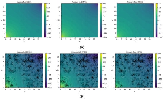
Figure 7.
Numeric pressure field solutions and flow directions (black arrows) for (a) homogeneous permeability field; (b) heterogeneous permeability field.
Visually, all realized numerical methods provided practically identical solutions for homogeneous and heterogenous fields. Looking more closely into the flow directions, it can be seen that the FDM and TPFA methods are very closely related, while MPFA provides slightly different flow directions compared to FDM or TPFA. FDM solutions were used as basis for comparisons between methods to indicate how closely related the methods are. The accuracy and processing time results are presented in the following table (Table 2).

Table 2.
Accuracy and speed comparison for numerical methods.
The results indicate that TPFA closely matches the FDM solution in both homogeneous and heterogeneous permeability fields, with extremely low MAE and MSE values with the order of 10−12 or smaller, while also being the fastest method with only 10 ms processing time. On the other hand, MPFA indicates considerable deviations from the FDM reference, with errors up to 285.5 and MAE up to 13.04. Furthermore, MPFA requires 29 ms, making it the slowest of the studied approaches. According to these findings, MPFA adds more numerical diffusion or complexity, particularly in heterogeneous circumstances, but TPFA offers outstanding accuracy and computing efficiency. This might be because MPFA has a broader formulation for addressing grid and permeability anisotropies.
3.3. Solution Using Deep Learning
In the following sections, each deep learning method’s results are presented: several test cases and accuracies for the permeability fields are shown in Figure 6.
3.3.1. Challenges of Using PINN
Most issues were encountered while trying to realize the PINN model. Since the single model’s training time was about 15 min using GPU, several different versions were tried out. However, the results provided were way far from the expected ones and those provided by numerical methods. Several failed attempts are provided below (Figure 8):

Figure 8.
Pressure field solutions by several different PINN models for homogeneous permeability field.
The most promising result seemed to learn a homogeneous permeability field, while the provided permeability field was heterogeneous. It could be seen that the number of collocation points completely captured the dynamic of the permeability field, but still the solution did not converge. For this unsuccessful attempt, the PINN model is excluded from further results (Figure 9).

Figure 9.
Pressure field solution sampled collocation points and input permeability field for one of PINN models.
3.3.2. Normalization of Pressure Field Solution
While training CNN and FNO models, in total 10,000 different permeability-pressure fields were generated (pressure fields were made by the FDM solver). The dataset was split into 80% training and 20% testing sets. For numerical stability, each permeability and pressure field were standardized using the generated dataset’s mean and standard deviation values. This imposed a dilemma: regular numerical solvers provided unscaled pressure fields, but CNN and FNO would provide standardized pressure fields. To combat this, two approaches were analyzed:
- Train models with fully standardized data and, afterwards, rescale the prediction using saved mean and standard deviation values.
- Train models with only standardized permeability fields and unchanged pressure fields. This ensures the final prediction will not be scaled, but numerical stability is not ensured.
Firstly, the CNN model. By running both approaches, the training time was not affected, and the difference was minimal. The MAE metric for the first approach was and for the second—43.925911. The MSE value for the first approach was and for the second—3032.616211. The increase in metrics was expected due to the final predictions’ different scales. However, looking into visual predictions, the first approach seems to provide better results. The following figures provide four main images: input permeability and pressure fields, predicted pressure field solution, and absolute difference between true and predicted pressure fields (Figure 10). Each row represents a different testing sample.
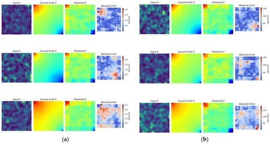
Figure 10.
(a) CNN training results for fully standardized data; (b) CNN training results for only standardized permeability fields.
Secondly, the FNO model. By running both approaches, the training time was not affected, and the difference was minimal. The MAE metric for the first approach was and for the second—. The MSE value the for first approach was and for the second—. The increase in metrics was expected due to the final predictions’ different scales, but compared to the CNN model, they were way smaller. Once again, looking into visual predictions, the first approach seems to provide better results. The following figures follow the same structure as the previous ones (Figure 11). Overall, standardizing pressure fields leads to better convergence and visually more consistent results. In further sections, these two approaches are compared with all other tried methods and more concrete conclusions are derived.
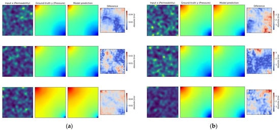
Figure 11.
(a) FNO training results for fully standardized data; (b) FNO training results for only standardized permeability fields.
3.3.3. Results
The trained CNN and FNO models were tested on the same permeability fields defined in Figure 6. Here, the fully standardized models are considered, and the final solution is then rescaled to match numerical solver solutions. Training metrics are provided in the table below (Table 3).

Table 3.
Deep learning models’ training metrics.
The predicted pressure fields and flow directions for initially generated permeability fields (Figure 12):
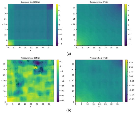
Figure 12.
Deep learning provided pressure field solutions and flow directions (black arrows) for (a) homogeneous permeability field; (b) heterogeneous permeability field.
The scale was still missed: true values should range from −300 to 300, but here values are not greater than the third of the original scale. The CNN solution has rectangular/square artifacts, which could be due to the same shape kernels used in the architecture. The FNO provides more continuous solutions. For homogeneous fields, it captures the dynamic perfectly, even if it has not seen a homogeneous field while training, while for heterogeneous fields it somewhat tries to provide a similar solution as numerical methods, but scale differences really hurt the visualization.
For homogeneous fields, the FNO with only standardized permeability fields produced the closest results to the FDM solver, while other approaches had high accuracy drops in the range of 36–50 for MAE and 2840–3661 for MSE. Interestingly, the fully standardized CNN and FNO provide almost the same accuracy measures for homogeneous fields. For heterogeneous fields, the fully standardized CNN provides the closest results to the FDM solver. On the other hand, predicted non-standardized pressure fields hurt both models 2–4 times. Inference times are consistent for both standardization approaches: 2 ms for the CNN and 18 ms for the FNO. Using GPU support, this inference could be further sped up, especially for larger and/or finer grids.
3.4. Comparison
For better comparison, each method’s prediction was compared by simply subtracting predicted fields and visualizing absolute differences. Darker blue spots indicate little to no difference, while bright red spots show the spots where methods truly disagree. The comparison plot is provided for heterogeneous permeability field case.
From the Figure 13, several important insights are revealed by contrasting machine learning-based and numerical solvers. The trustworthiness of TPFA as a finite-volume solution for this problem is confirmed by the virtually identical results obtained from the FDM and TPFA approaches. However, MPFA exhibits significant differences from both FDM and TPFA [21,22], most likely because of its improved ability to handle non-orthogonal grids or anisotropy. The neural solvers CNN and FNO can approximate solutions, but they fall short of the precision of classical techniques because of their greater errors, especially around borders, as compared to older methods. Furthermore, the difference between CNN and FNO solutions suggests that architectural differences significantly impact the solution. Even if numerical solutions are still more accurate, deep learning approaches have potential and could still be improved [23].
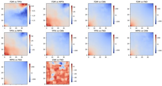
Figure 13.
Pressure field solution comparison between each analyzed method pair for heterogeneous permeability field.
Comparing Table 2 with Table 4, the most resemblance to the FDM method was TPFA and FNO with no prediction standardization for homogeneous permeability. They both achieved small MAE and MSE metrics. Other methods had higher MAE and especially high MSE values. The most different was MPFA, which is in the middle regarding accuracy metrics. For heterogeneous permeability, only the TPFA method is close to the FDM method, while others provide increased errors [21,22]. This indicates that a simpler homogeneous permeability field is not only easier for fluid to pass through, but for the methods to solve as well.

Table 4.
Accuracy and speed comparison for deep learning methods.
Regarding inference times, the type of permeability field did not have an impact on processing time. The fastest was the CNN, while the slowest—MPFA. However, the FNO was 11 ms faster than the MPFA. Since it learns on generated data, the FNO could learn to map MPFA solutions and replace the MPFA solver as a faster alternative that provides almost identical results.
Comparing methods regarding the permeability field’s type, all tested approaches performed better on homogenous permeability fields than on heterogenous ones. Both MAE and MSE values were consistently higher in the presence of non-uniform permeability, with the exception of the FDM, which was used as the ground truth for comparisons. In terms of computational speed, none of the methods showed sensitivity to the type of permeability field. This outcome is expected, since NN approaches need only to learn the solution operator and then inference time remains constant regardless of input variability. The numerical methods construct linear systems of equations whose structure remains unchanged by variations in permeability values, of which only the coefficients may differ. This implies that permeability field type has no effect on the speed of the PDE solver but impacts its accuracy. To investigate potential inference speed drawbacks, the grid resolution or discretization step size should be different.
4. Conclusions and Recommendations for Further Work
The literature review uncovered the relevance of numerical solutions for the elliptic partial differential equation problem for single-phase flow in porous media. With accurate simulation, real-life decisions could be made less costly and more efficient. For that reason, there are several pre-built simulation tools. Furthermore, nowadays deep learning methods are arising as a new potential numerical solver which could further improve traditional numerical solvers.
The Darcy flow equation for this paper was formulated and different permeability field types were generated. From strictly uniform, to strictly structured, to completely random fields. The generation of these fields is simple and only limited by the researcher’s imagination. For further tasks, one homogenous and heterogenous Gaussian permeability fields were chosen.
Classical numerical methods were realized and FDM/TPFA similarities emerged from visual and accuracy evaluation. All three analyzed methods provided with visually similar pressure fields for both chosen permeability field types. However, FDM and TPFA were remarkably similar with MAE values in the scale of –. The TPFA method was 6 milliseconds faster, meaning it could be used as replacement for FDM without any cost to accuracy for finer grids. The MPFA method differed from the latter methods more due to its different stencil formulation.
Deep learning methods were realized, but challenges regarding it and prediction interpretations were imposed. After many experiments, the PINN model was never fully realized, implying the difficulty of its implementation and the need for a better package with wrappers for simpler usage. The CNN model provided structural errors which correspond to its square convolutional kernels; thus, the provided pressure solution seems “blocky”. The FNO model produced the most promising results, but their comparison with regular numerical solvers was hard due to data standardization steps for numerical stability while training. While full training data standardization provided better accuracy metrics, it made comparison with traditional numerical methods harder due to scale differences.
From all analyzed methods, the TPFA gave the best results compared to the FDM, the MPFA was in the middle, and the CNN was the worst. However, the FNO was fast at inference, indicating it could be used as a faster alternative for the MPFA or other traditional methods due to its ability to learn mappings and no need of iteration over discretized grid. Different permeability field types (homogenous and heterogenous) only had an impact on each method’s accuracy, but not the computational time.
There is significant potential for further improvement in the research presented in this paper. One direction is to compare deep learning methods with established numerical solvers such as the finite volume method (FVM) or the mixed finite element method (MFEM). Additionally, improving the PINN realization and generating solutions for comparison with numerical methods would provide valuable insights.
Another possibility is to analyze the impact of different grid sizes on discretization methods, particularly in terms of accuracy and processing times. It is hypothesized that inference times for numerical methods increase exponentially with grid size, which may highlight the advantage of the FNO as a substitute for computationally heavy methods such as the MPFA. Similarly, operating memory usage, which was not addressed in this work, warrants further investigation to optimize efficiency across the methods.
Further research could also explore the limits of grid discretization size, identifying which of the proposed methods are most suitable for the largest grids. Likewise, while several heterogeneous permeability fields were generated, only one type was tested. Extending this analysis to include additional heterogeneities—such as faults, fractures, or vugs, would expand the scope and applicability of the findings.
The current results are presented for 2D cases, while Darcy flow problems in real-world scenarios are inherently 3D. Future work should extend to three-dimensional simulations, allowing parameters such as viscosity, porosity, and density to vary spatially or temporally rather than being held constant. In addition, testing the robustness of methods under different initial and boundary conditions, or with varying source and sink terms, would further strengthen the conclusions.
Finally, to apply these methods to practical problems, additional research is required to incorporate effects such as compressibility, multiphase flow, and flow through fractured media. These considerations would bring the methodology closer to real-world reservoir conditions and enhance its value for practical applications.
Author Contributions
Conceptualization, K.J. and G.S.; methodology, K.J. and G.S.; software, K.J. and G.S.; validation, K.J. and G.S.; formal analysis, G.S.; investigation, G.S.; resources, K.J.; data curation, K.J. and G.S.; writing—original draft preparation, G.S. and K.J.; writing—review and editing, G.S., K.J. and M.P.; visualization, G.S. and K.J.; supervision, M.P. All authors have read and agreed to the published version of the manuscript.
Funding
This research received no external funding.
Data Availability Statement
The original contributions presented in this study are included in the article. Further inquiries can be directed to the corresponding author.
Conflicts of Interest
The authors declare no conflicts of interest.
Abbreviations
The following abbreviations are used in this manuscript:
| ODE | Ordinary Differential Equation |
| PDE | Partial Differential Equation |
| FDM | Finite Difference Method |
| TPFA | Two-Point Flux Approximation |
| MPFA | Multi-Point Flux Approximation |
| NN | Neural Network |
| CNN | Convolutional Neural Network |
| PINN | Physics-Informed Neural Network |
| FNO | Fourier Neural Operator |
Appendix A
In this appendix three graph visualizations are provided for the used neural network architectures: CNN, PINN, and FNO.
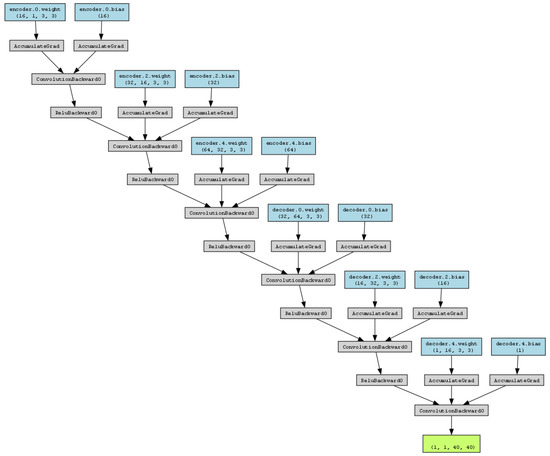
Figure A1.
Used CNN architecture.

Figure A2.
Used PINN architecture.
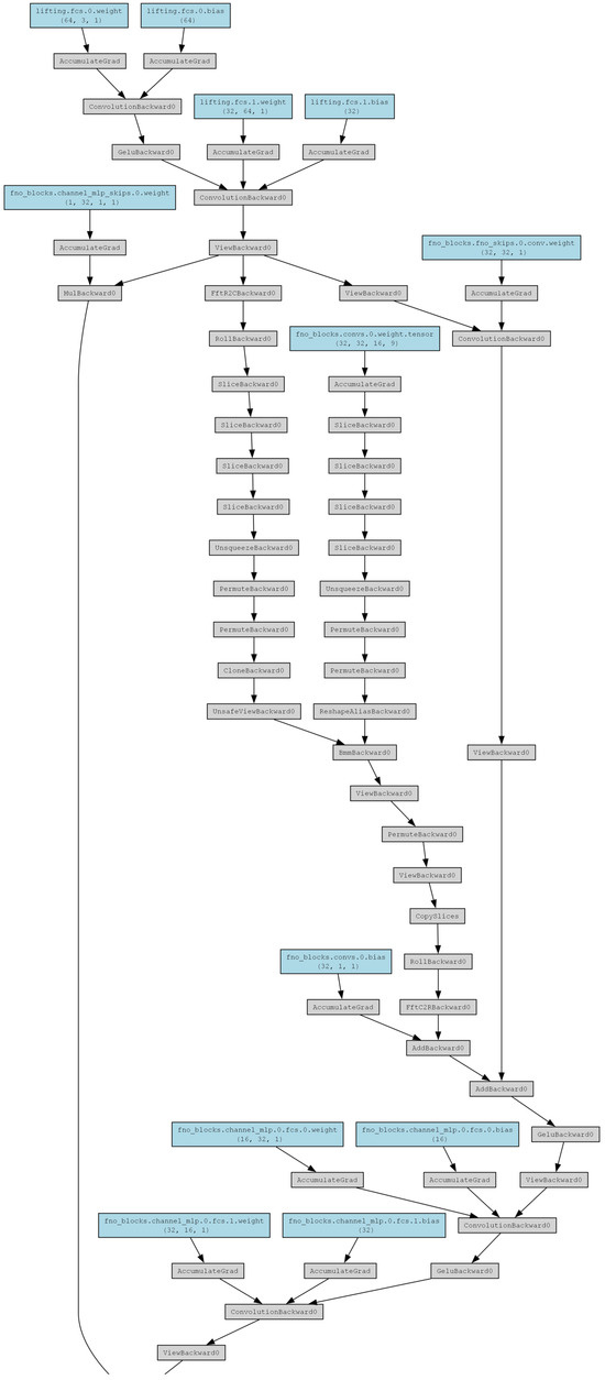
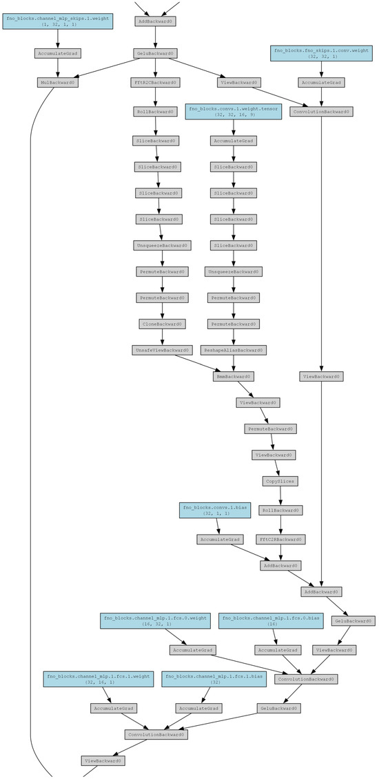
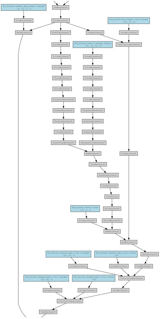
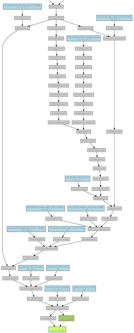
Figure A3.
Used FNO architecture.
References
- Advancing Energy Through Research in Porous Media—Texas A&M Energy Institute. Available online: https://energy.tamu.edu/news_item/advancing-energy-through-research-in-porous-media/ (accessed on 15 June 2025).
- Hussain, Y.; Uagoda, R.; Borges, W.; Nunes, J.; Hamza, O.; Condori, C.; Aslam, K.; Dou, J.; Cárdenas-Soto, M. The Potential Use of Geophysical Methods to Identify Cavities, Sinkholes and Pathways for Water Infiltration. Water 2020, 12, 2289. [Google Scholar] [CrossRef]
- Memon, A.R.; Makauskas, P.; Kaminskaitė-Baranauskienė, I.; Pal, M. Repurposing depleted hydrocarbon reservoirs for geothermal energy: A case study of the Vilkyčiai Cambrian sandstone in Lithuania. Energy Rep. 2025, 14, 243–253. [Google Scholar] [CrossRef]
- Verma, A.; Dangi, S.L.; Malik, S.; Pal, M. Investigating CO2 and hydrogen flow dynamics and efficiency optimization for underground storage and production: An experimental and simulation-based study. Energy Rep. 2025, 13, 5815–5827. [Google Scholar] [CrossRef]
- Malik, S.; Makauskas, P.; Karaliūtė, V.; Pal, M.; Sharma, R. Assessing the geological storage potential of CO2 in Baltic Basin: A case study of Lithuanian hydrocarbon and deep saline reservoirs. Int. J. Greenh. Gas Control 2024, 133, 104097. [Google Scholar] [CrossRef]
- Pal, M.; Karaliūtė, V.; Malik, S. Exploring the Potential of Carbon Capture, Utilization, and Storage in Baltic Sea Region Countries: A Review of CCUS Patents from 2000 to 2022. Processes 2023, 11, 605. [Google Scholar] [CrossRef]
- Ghalambor, A.; Economides, M.J. Formation Damage: Fundamentals and Applications in Petroleum Engineering; Gulf Publishing Company: Houston, TX, USA, 2000. [Google Scholar]
- World, B.G. Offshore Oil and Gas Development. Environmental, Health, and Safety Guidelines; World Bank: Washington, DC, USA, 2017. [Google Scholar]
- Domenico, P.A.; Schwartz, F.W. Physical and Chemical Hydrogeology, 2nd ed.; Wiley: New York, NY, USA, 1998. [Google Scholar]
- Alley, W.M.; Reilly, T.E.; Franks, B. Sustainability of Ground-Water Resources; U.S. Geological Survey: Reston, VA, USA, 1999.
- Waltham, T.; Bell, F.; Cuslshaw, M. Sinkholes and Subsidence: Karst and Cavernous Rocks in Engineering and Construction; Springer: Berlin/Heidelberg, Germany, 2005. [Google Scholar]
- Zhou, W.; Beck, B.F.; Adams, A.L. Effective Grouting in Karst Formations. Eng. Geol. 2002, 65, 167–185. [Google Scholar] [CrossRef]
- International, E.A. CCUS in Clean Energy Transitions; IEA: Paris, France, 2020. [Google Scholar]
- Bandilla, K.W.; Celia, M.A.; Leister, E. Impact of Model Complexity on CO2 Plume Modeling. Int. J. Greenh. Gas Control 2015, 42, 219–230. [Google Scholar] [CrossRef]
- Rutqvist, J. The Geomechanics of CO2 Storage in Deep Sedimentary Formations. Geotech. Geol. Eng. 2012, 30, 525–551. [Google Scholar] [CrossRef]
- Randolph, J.B.; Saar, M.O. Coupling CO2 Storage with Geothermal Energy Production. Geophys. Res. Lett. 2011, 38, 10. [Google Scholar] [CrossRef]
- Aarnes, J.E.; Gimse, T.; Lie, K. An Introduction to the Numerics of Flow in Porous Media using Matlab. In Geometric Modelling, Numerical Simulation, and Optimization: Applied Mathematics at SINTEF; Springer: Berlin/Heidelberg, Germany, 2007; pp. 265–306. ISBN 9783540687825. [Google Scholar] [CrossRef]
- Aaavatsmkar, I. An Introduction to Multipoint Flux Approximations for Quadrilateral Grids. Comput. Geosci. 2002, 6, 405–432. [Google Scholar] [CrossRef]
- Chen, Z.; Huan, G.; Ma, Y. Computational Methods for Multiphase Flows in Porous Media; Society for Industrial and Applied Mathematics (SIAM): Philadelphia, PA, USA, 2006; ISBN 9780898716061. [Google Scholar] [CrossRef]
- Edwards, M.G.; Rogers, C.F. Finite Volume Discretization with Imposed Flux Continuity for the General Tensor Pressure Equation. Comput. Geosci. 1994, 1, 259–290. [Google Scholar] [CrossRef]
- Makauskas, P.; Pal, M. Stable Multipoint Flux Approximation (MPFA) Saturation Solution for Two-Phase Flow on Non-K-Orthogonal Anisotropic Porous Media. Technologies 2025, 13, 193. [Google Scholar] [CrossRef]
- Makauskas, P.; Pal, M. Stable Multipoint Flux Approximation (MPFA) for Anisotropic porous media. Alex. Eng. J. 2025, 117, 418–429. [Google Scholar] [CrossRef]
- Makauskas, P.; Pal, M.; Kulkarni, V.; Kashyap, A.S.; Tyagi, H. Comparative study of modelling flows in porous media for engineering applications using finite volume and artificial neural network methods. Eng. Comput. 2023, 39, 3773–3789. [Google Scholar] [CrossRef]
- Liu, J.; Sadre-Marandi, F.; Wang, Z. DarcyLite: A Matlab Toolbox for Darcy Flow Computation. Procedia Comput. Sci. 2016, 80, 1301–1312. [Google Scholar] [CrossRef]
- Lie, K. An Introduction to Reservoir Simulation Using MATLAB/GNU Octave: User Guide for the MATLAB Reservoir Simulation Toolbox (MRST); Cambridge University Press: Cambridge, CA, USA, 2019; ISBN 9781108492430. [Google Scholar] [CrossRef]
- Model Mass, Momentum, and Energy Transport in Porous Media. Available online: https://www.comsol.com/porous-media-flow-module (accessed on 15 June 2025).
- OpenFOAM Documentation—Home. Available online: https://doc.openfoam.com (accessed on 15 June 2025).
- Khormali, A.; Ahmadi, S.; Aleksandrov, A.N. Analysis of Reservoir Rock Permeability Changes due to Solid Precipitation during Waterflooding using Artificial Neural Network. J. Pet. Explor. Prod. Technol. 2025, 15, 17. [Google Scholar] [CrossRef]
- Dieva, N.; Aminev, D.; Kravchenko, M.; Smirnov, N. Overview of the Application of Physically Informed Neural Networks to the Problems of Nonlinear Fluid Flow in Porous Media. Computation 2024, 12, 69. [Google Scholar] [CrossRef]
- Almajid, M.M.; Abu-Al-Saud, M.O. Prediction of Porous Media Fluid Flow using Physics Informed Neural Networks. J. Pet. Sci. Eng. 2022, 208, 109205. [Google Scholar] [CrossRef]
- Li, Z.; Kovachki, N.; Azizzadenesheli, K.; Liu, B.; Bhattacharya, K.; Stuart, A.; Anandkumar, A. Fourier Neural Operator for Parametric Partial Differential Equations. arXiv 2021, arXiv:2010.08895. [Google Scholar] [CrossRef]
- Liu, Y.; Yang, S.; Zhang, N.; Cao, J.; Guo, C. Simulation Enhancement GAN for Efficient Reservoir Simulation at Fine Scales. Math. Geosci. 2024, 56, 1439. [Google Scholar] [CrossRef]
- Charhabil, A.; Jelti, S.; Serghini, A.; Hajaji, A.E. Numerical Modeling of the Flow in a Completely Saturated Zone. Alex. Eng. J. 2022, 61, 3187–3199. [Google Scholar] [CrossRef]
- Venkatramanan, S.; Sekar, S.; Viswanathan, P.M. Groundwater Contamination in Coastal Aquifers, 1st ed.; Elsevier Science: San Diego, CA, USA, 2022; ISBN 0128243872. [Google Scholar] [CrossRef]
- Mora, I.R.; García-Toral, D.; Rubio-Arellano, A.; Vázquez-Báez, V. Modeling an Aquifer: Numerical Solution to the Groundwater Flow Equation. Math. Probl. Eng. 2019, 2019, 1613726. [Google Scholar] [CrossRef]
- Das, B.; Steinberg, S.; Weber, S.; Schaffer, S. Finite Difference Methods for Modeling Porous Media Flows. Transp. Porous Media 1994, 17, 171–200. [Google Scholar] [CrossRef]
- Saad, Y. Iterative Methods for Sparse Linear Systems, 2nd ed.; SIAM, Soc. for Industrial and Applied Mathematics: Philadelphia, PA, USA, 2003. [Google Scholar]
- Chen, J.; Gildin, E.; Killough, J.E. Transfer Learning-Based Physics-Informed Convolutional Neural Network for Simulating Flow in Porous Media with Time-Varying Controls. Mathematics 2024, 12, 3281. [Google Scholar] [CrossRef]
- Wang, N.; Chang, H.; Zhang, D. Surrogate and Inverse Modeling for Two-Phase Flow in Porous Media Via Theory-Guided Convolutional Neural Network. J. Comput. Phys. 2022, 466, 111419. [Google Scholar] [CrossRef]
- Guo, X.; Li, W.; Iorio, F. Convolutional Neural Networks for Steady Flow Approximation. In Proceedings of the 22nd ACM SIGKDD International Conference on Knowledge Discovery and Data Mining, San Francisco, CA, USA, 13–17 August 2016. [Google Scholar] [CrossRef]
- Raissi, M.; Perdikaris, P.; Karniadakis, G.E. Physics-Informed Neural Networks: A Deep Learning Framework for Solving Forward and Inverse Problems Involving Nonlinear Partial Differential Equations. J. Comput. Phys. 2018, 378, 686. [Google Scholar] [CrossRef]
- Pu, R.; Feng, X. Physics-Informed Neural Networks for Solving Coupled Stokes–Darcy Equation. Entropy 2022, 24, 1106. [Google Scholar] [CrossRef]
- Lu, L.; Jin, P.; Zhang, Z.; Karniadakis, G.E. Learning nonlinear operators via DeepONet based on the universal approximation theorem of operators. Nat. Mach. Intell. 2021, 3, 218–229. [Google Scholar] [CrossRef]
- Kovachki, N.; Li, Z.; Liu, B.; Azizzadenesheli, K.; Bhattacharya, K.; Stuart, A.; Anandkumar, A. Neural Operator: Learning Maps between Function Spaces with Applications to PDEs. J. Mach. Learn. Res. 2023, 24, 1–97. [Google Scholar]
Disclaimer/Publisher’s Note: The statements, opinions and data contained in all publications are solely those of the individual author(s) and contributor(s) and not of MDPI and/or the editor(s). MDPI and/or the editor(s) disclaim responsibility for any injury to people or property resulting from any ideas, methods, instructions or products referred to in the content. |
© 2025 by the authors. Licensee MDPI, Basel, Switzerland. This article is an open access article distributed under the terms and conditions of the Creative Commons Attribution (CC BY) license (https://creativecommons.org/licenses/by/4.0/).