Article

Comparative Simulation of Solar Adsorption and Absorption Cooling Systems with Latent Heat Storage with Erythritol and MgCl2·6H2O

by
Rosenberg J. Romero
1,
Fernando Lara
2,
Eduardo Venegas-Reyes
3,
Moisés Montiel-Gonzalez
4 and
Jesús Cerezo
1,*
1
Engineering and Applied Research Centre, CIICAp, Autonomous University of Morelos State, Av. Universidad 1001, Cuernavaca 62209, Morelos, Mexico
2
Facultad de Ingeniería, Universidad Autonoma de Baja California, Blvd. Benito Juarez S/N, Mexicali 21280, Baja California, Mexico
3
Coordinación de Seguridad Hídrica, Instituto Mexicano de Tecnología del Agua, Blvd. Cuauhnáhuac 8532, Jiutepec 62550, Morelos, Mexico
4
Facultad de Ciencias Químicas e Ingeniería, Universidad Autónoma del Estado de Morelos, Av. Universidad 1001, Cuernavaca 62209, Morelos, Mexico
*
Author to whom correspondence should be addressed.
Processes 2025, 13(8), 2655; https://doi.org/10.3390/pr13082655
Submission received: 3 July 2025 / Revised: 14 August 2025 / Accepted: 18 August 2025 / Published: 21 August 2025

Abstract

The energy requirements for conditioning spaces have been increasing primarily due to population growth and climate change. This paper shows a comparison between an adsorption (ADC) and absorption cooling (ABC) systems to keep a building below the 25 °C set-point in dynamic conditions, utilizing a latent heat storage tank with MgCl2·6H2O and erythritol, and employing evacuated tube and parabolic trough collectors. The storage tank geometry is a plate heat exchanger. An auxiliary system was incorporated to control the temperature range of the solar cooling systems. The results showed that the coefficient of performance was kept around 0.40–0.60 and 0.70 for adsorption and absorption cooling, respectively. The latent heat storage tank with erythritol captured more solar energy than MgCl2·6H2O. A maximum solar fraction of 0.96 was obtained with MgCl2·6H2O, a thickness of 0.15 m, 20 m2 of parabolic trough collector area, and absorption cooling, while the energy supply was fully satisfied with a solar collector with erythritol, a thickness of 0.1 m, 13 m2 of parabolic trough area, and absorption cooling. In general, erythritol obtained better results of solar collector fractions than MCHH; however, it has less thermal stability than MgCl2·6H2O, and the cost is higher.

1. Introduction

The use of air conditioners and refrigeration accounts for approximately 15% of the world’s total electricity production [1]. This consumption exhibits an increasing trend due to demographic growth, as well as the impact of global warming. Solar thermal-driven refrigeration and cooling technology [2] is a promising renewable and sustainable technology for reducing greenhouse gas emissions.
Solar energy can be utilized to meet the heat requirements for sorption cooling systems in a sustainable manner, such as absorption cooling (ABC) and adsorption cooling (ADC) technologies. One of its limitations is its intermittent nature; therefore, the development of energy storage systems has become crucial [2]. A latent heat storage tank (LHST) has an advantage due to its high energy storage density and the ability to operate at a constant or near-constant temperature compared to storage tanks without phase change.
Studies related to LHST-coupled absorption systems in dynamic conditions are presented. Fan et al. [3] analyzed a shell-and-tube heat exchanger with hydroquinone as PCM in a solar-driven H2O/LiBr double-effect absorption system. The enthalpy method was used to model the phase change. The results showed that natural convection is an essential parameter in the solidification process. Additionally, 100 kW of cooling capacity was fulfilled with a 12.55 m3 storage tank.
Pintaldi et al. [4] compared sensible (water and oil) and latent heat (KNO3/NaNO3 and AlSn) storage systems in a vertical shell-and-tube configuration, coupled to a triple-effect chiller and a parabolic trough collector (PT) at 200 °C. The results showed that the LHST obtained higher storage efficiencies than sensible heat storage systems. On the other hand, the sensible heat storage tank obtained better results with solar collectors than the LHST.
Zhou et al. [5] analyzed a single and a double hybrid effect absorption cooling device coupled with a linear Fresnel solar system. A typical shell-and-tube configuration was used as a storage tank to store molten salt. The COP varied from 0.73 to 1.09 for the single and double effect absorption systems. The optimized solar collector area (ASC) and thermal storage capacity obtained values from 900 to 1100 m2 and 5.0 to 8.5 m3, respectively.
Cerezo et al. [6] analyzed a solar absorption cooling system using a flat plate heat exchanger as LHST with MgCl2·6H2O (MCHH) in dynamic conditions with a PT, alongside water and synthetic organic fluid as the heating fluid using TRNSYS 17 software. Three configurations were evaluated: (a) sensible storage tank, (b) LHST, and (c) LHST with a tempering valve. The result showed that the sensible heat (configuration 1) did not fulfill the energy demand. Configurations (b) and (c) satisfy the demand using an LHST of 0.5 m3 with 30 m2 and 20 m2 of ASC, respectively, and utilizing water as the thermal fluid. Water obtained better results than synthetic organic fluid, primarily due to its higher thermal conductivity.
Mehmood et al. [7] analyzed a solar absorption cooling to optimize the size of essential components, comparing conventional sensible heat and LHST in a configuration of a vertical cylinder with Rubitherm SP90 as PCM heated by evacuated tube collectors (ET) using TRNSYS software. The results showed that a 1.5 m2/kWth latent heat storage tank, 30 L/m2, and an insulation below 0.8 W/m2 were selected to optimize the solar fraction (SF). The use of LHST increases the SF by 4% more than a conventional tank.
Migla et al. [8] presented an optimization of an absorption cooling system coupled to a vacuum solar collector and an LHST with different geometries (cylinders, spheres, and plates) using RT90HC as PCM, simulated in TRNSYS software. The results showed a 6.2% reduction in auxiliary energy.
Hosseini [9] designed and analyzed an ABC coupled to an LHST. The system consists of a cylindrical tank with multiple inner tubes through which the heating fluid (HF) passes using erythritol (ERY) as PCM, which is located between the inner tubes and the outer cylinder. The behavior of the system during charging and discharging was studied by varying the radius of the tubes, the mass of PCM, and the number of tubes. It was determined that, as the number of tubes and their radius increase, the efficiency of the LHST increases and the charging time decreases. The discharge process was studied by integrating the LHST with the maximum energy demand of the generator. It was concluded that the system provides more than 10 h of hot water at the necessary temperature to operate the cooling system.
Poshtiri and Jafari [10] analyzed an ADC in dynamic conditions to provide air conditioning during 24 h with stearic acid as PCM in a shell-and-tube heat exchanger, heated by flat solar collectors. The results showed that the air changes per hour and the fresh air ratio decreased the SF and increased auxiliary energy consumption. The reduction of the fresh air ratio from 100% to 20% increased the operation time of the chiller without PCM by approximately 2.5 h.
Studies on sorption systems coupled to an LHST are still very few, primarily for adsorption systems. The advantage of the ABC is its higher coefficient of performance (COP) compared to the ADC. On the other hand, the temperature of activation for adsorption is lower than that of absorption cooling, so a simple solar collector, such as a flat plate or ET, can be used. The use of PCM to store thermal energy is of great importance for the sorption cooling systems due to their high capacity to store heat in a small volume. This work shows an analysis of adsorption (ADC) and absorption cooling (ABC) systems heated by PT and ET using an LHST with MCHH and ERY as PCM to air-condition a building. Essential parameters of PCMs will be analyzed based mainly on PCM thermal properties and solar fraction. Both PCMs have similar melting temperatures; however, the latent heat of ERY is almost twice that of MCHH, while MCHH has a better thermal conductivity in the liquid phase than ERY.

2. Materials and Methods

2.1. Adsorption and Absorption Cycles

Absorption (ABC) and adsorption (ADC) cooling systems are based on the liquid and solid sorption processes, respectively. Sorption is a process that involves the absorption and desorption of a substance, known as a refrigerant, by a sorbent. The ABC cycle is composed of four components: generator, condenser, evaporator, and absorber, see Figure 1a. The thermodynamic cycle operates at two levels of pressure and usually three levels of temperature. The process serves as follows. Heat is supplied to the generator to vaporize the liquid refrigerant from the poor solution (low concentration). The refrigerant in the vapor phase is directed to the condenser device; in this part of the cycle, it releases heat (QCO). Then, the refrigerant in the liquid phase moves into a throttling valve to decrease its pressure and its temperature. This liquid is heated (QEV) in the evaporator until it reaches the vapor phase, and it is blended in the absorber device to create the rich solution (high concentration) from the generator. This physical/chemical sorption delivers heat (QAB), which is transferred to the environment. To maintain the steady-state cycle, the poor solution is pumped back to the generator. Typically, a single- or twice-cooling tower was used to absorb the heat from the absorber and condenser.
The ADC system is constructed from components such as ABC [11]; however, heat transfer can be achieved in two phases (Figure 1b). The first phase is the adsorption process: the refrigerant enters the evaporator, removing heat (QEV). After that, the refrigerant in the vapor phase enters the adsorber, where it is adsorbed into an adsorber bed and heat is dissipated (QAD). The second phase is the desorption process: the desorber (or generator) is heated (QDE) to evaporate the refrigerant and enters the condenser, dissipating a quantity of energy (QCO). It then moves through the throttling valve into the evaporator. To ensure the continuous operation of the adsorption chiller, two beds are used, in which the adsorption and desorption processes occur simultaneously as the chambers switch.

2.2. Description of the Solar Cooling System

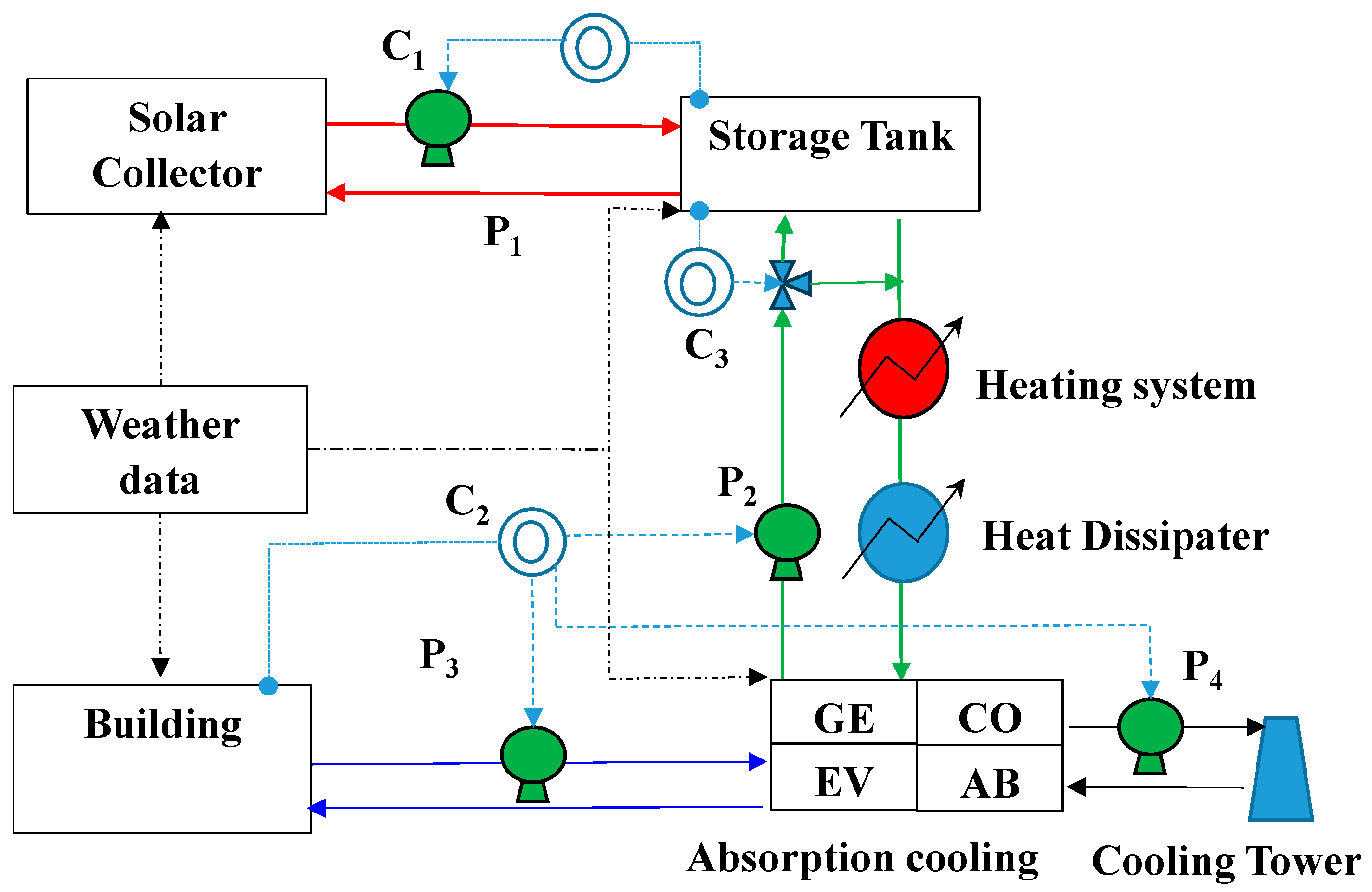
Figure 2 illustrates a diagram of the solar absorption cycle, comprising three primary circuits: the solar collector (represented by two red lines), the storage tank (represented by two green lines), and the chilled water (represented by two blue lines). In the operation with a solar configuration, an HF is pumped (P1) from the LHST into the solar collector and returned to the tank. In the storage tank configuration, the HF is pumped (P2) from the LHST to transfer energy at the generator (GE) of the ABC. When the temperature of the LHST falls outside the operational range of the solar collector, a heating system or a heat dissipater is activated, controlling the generator temperature range (TGE, as shown in Table 1). Finally, in the chilled water circuit, chilled water is pumped (P3) from the evaporator (EV) of the ABC to the building and returns to it. The heat dissipated by the condenser (CO) and absorber (AB) is sent to a cooling tower.
The pump P1 is activated by a differential controller (C1). The controller opens or closes the fluid circuit when the output temperature is higher than the input temperature of the fluid in the storage tank or when the surface temperature of the PCM (placed at the outlet of the heating fluid) reaches 1 °C above the melting point (117 °C for MCHH and 119 °C for ERY, respectively). A thermostat (C2) is used to control the building’s temperature at 25 °C, which in turn activates P2, P3, and P4. A differential controller (C3) regulates the flow rate entering the LHST. When the temperature of the surface PCM (placed at the same point as control C1) is one degree centigrade lower than its melting point, the flow rate is directed directly to the heating system; otherwise, it enters the LHST.
The components of the solar sorption system are simulated in TRNSYS software [12] using different types, described as follows.
Type 56 (Building) is a multi-zone building [13]. This component is simulated in a single zone with four windows. It is a simple house of 187 m3. Three occupants are in a resting position; more details can be found in [6]. The only difference in this work is that the building’s ceiling was isolated with a 0.10 m-thick layer of polyurethane to reduce energy losses.
Type 909 (Adsorption Chiller) and Type 107 (Single-Effect Absorption Chiller) utilize normalized catalog data taken to calculate the COP ratios as a function of the inlet temperature of chilled, cooling, and hot water [14]. The working fluids usually are water as a refrigerant and lithium bromide and silica gel as absorbent and adsorbent solutions. Table 1 presents the external input temperature range (TCHILLED) of the evaporator and the condenser and absorber (TCOOLING) components of the sorption cooling systems, as well as the set point temperature (TSET).
Table 2 provides a brief description of the types used and the mathematical references for the solar cooling system components [12,15].

2.3. Mathematical Model of the Latent Heat Storage Tank

Type 66d was used to simulate the LHST programmed in Engineering Equation Solver [18] from a TRNSYS simulation. The storage tank is a rectangular heat exchanger consisting of three flat containers filled with PCM, with the heating fluid flowing through four channels to extract or supply energy [6]. The mathematical model was developed based on the following assumptions:
  • Isothermal condition is considered in the phase change.
  • The PCM thermophysical properties are independent of temperature.
  • PCM is homogeneous and isotropic.
  • The thermal resistance of the metal wall in the plates is not taken into account.
  • Input and output transport properties of the HF are considered the same.
The mathematical model was solved using a finite difference scheme. In this work, each node was discretized for two dimensions. The m and n subscripts are the nodes in the x and y directions. The following equations represent the energy balance in transient conditions, expressed using the finite difference formulation and solved via the implicit method.
Heating fluid
m H F C p H F T m 1 , n i + 1 T m , n i + 1 + m H F C p H F T m + 1 , n i + 1 T m , n i + 1 + h t c H F i + 1 A y T m , n + 1 i + 1 T m , n i + 1 + h t c H F i + 1 A y T m , n 1 i + 1 T m , n i + 1 = ρ H F V H F h H F i + 1 h H F i t
where m, T, Cp, htc, and p are the flow rate (kg/s), temperature (°C), heat capacity (kJ/kg °C), convection heat transfer coefficient of the heating fluid (kW/m2 °C), and density (kg/m3), respectively; ΔV and ΔAy are volume element and the area in the y direction, respectively. h m , n i and h m , n i + 1 are the enthalpies of node m, n at times ti = iΔt and ti+1 = (i + 1)Δt, respectively. Δt is the step time.
PCM block in the sensible heat zone
k P C M A x T m 1 , n i + 1 T m , n i + 1 x + k P C M A x T m + 1 , n i + 1 T m , n i + 1 x + k P C M A y T m , n + 1 i + 1 T m , n i + 1 y + k P C M A y T m , n 1 i + 1 T m , n i + 1 y = ρ P C M V P C M h i + 1 h i t
PCM block in the latent heat zone
k E F F , P C M A x T m 1 , n i + 1 T m , n i + 1 x + k E F F , P C M A x T m + 1 , n i + 1 T m , n i + 1 x + k E F F , P C M A y T m , n + 1 i + 1 T m , n i + 1 y + k E F F , P C M A y T m , n 1 i + 1 T m , n i + 1 y = ρ P C M V P C M h i + 1 h i t
where Δx and Δy represent the spacing between nodal points in the rectangular mesh, h is the enthalpy, k is the thermal conductivity (kW/m °C), and kEFF is the effective conductivity and takes a value of kL × 4. More details and validation can be found in [6].
Table 3 shows the property values of ERY and MCHH [19] used in the calculations. An average temperature of 116.25 °C was considered the melting point of MCHH. MCHH has the advantage of having higher thermal diffusivity in the liquid phase than ERY. The cost of the MCHH is USD 174/kg (>99.0% wt.); in contrast, the ERY has a cost of USD 7755/kg [20]. On the other hand, ERY has almost double the value of thermal diffusivity in the solid phase. Additionally, the energy density suggests that it has a higher energy storage capacity. El-Sebaii et al. [21] reported that the MCHH has a thermal stability of 1000 cycles, as analyzed for solar cooking, while Agyenim et al. [22] reported a 7.5% reduction in latent heat after 20 cycles.
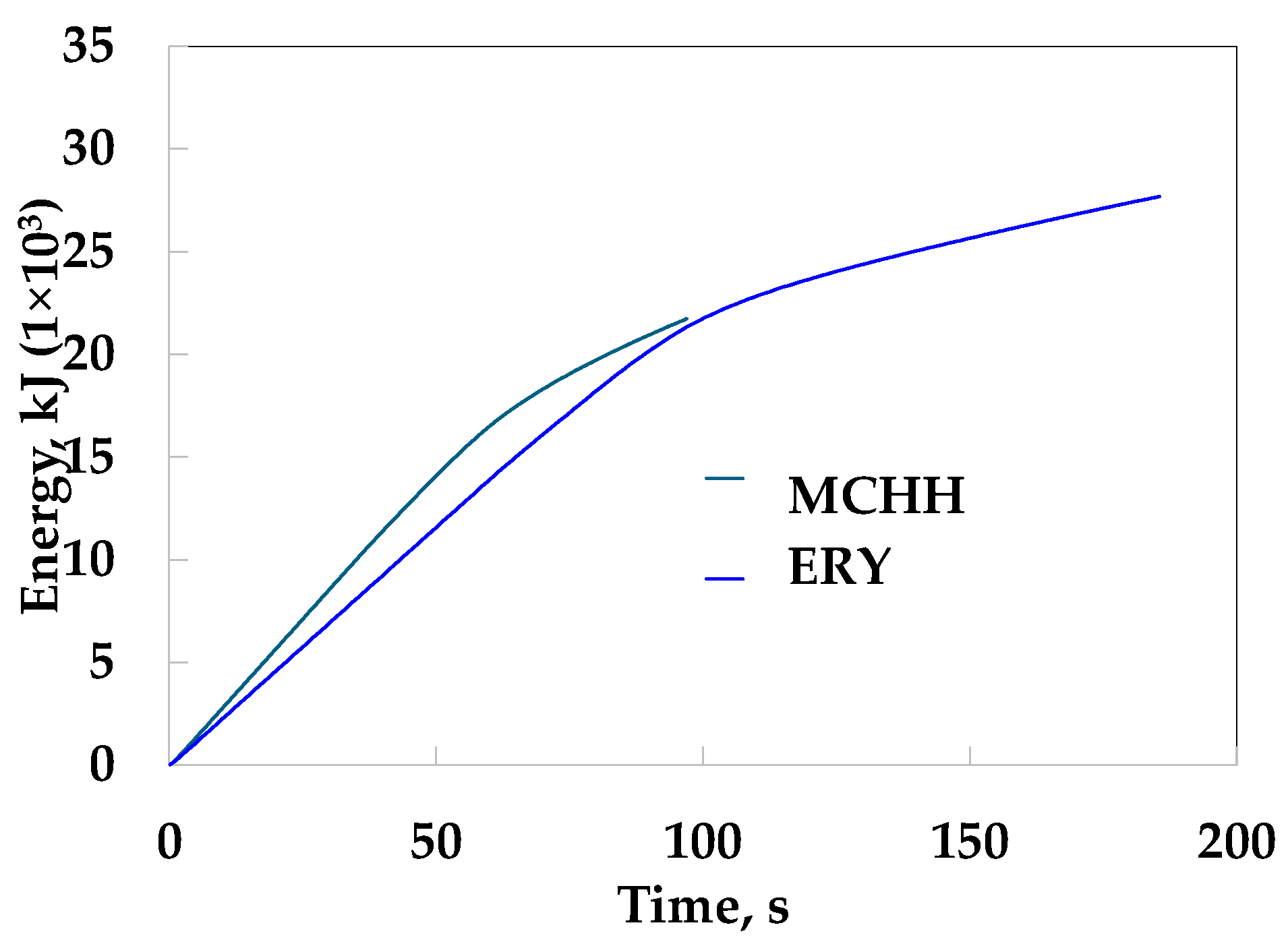
Figure 3 shows the energy of LHST using ERY and MCHH, and Table 4 shows the dimensions and input operation conditions. Erythritol stores more energy (27,790 kJ) than MCHH (21,700 kJ). This energy corresponds only to one of the four blocks of the tank; however, the phase change takes longer, as MCHH takes 100 min, while ERY takes 180 min. It can be observed that the slope changes because the PCM heats up (so it not only stores latent heat but also sensible heat), and this decreases the temperature difference between the heating fluid and PCM and reduces the heat transfer.

3. Results

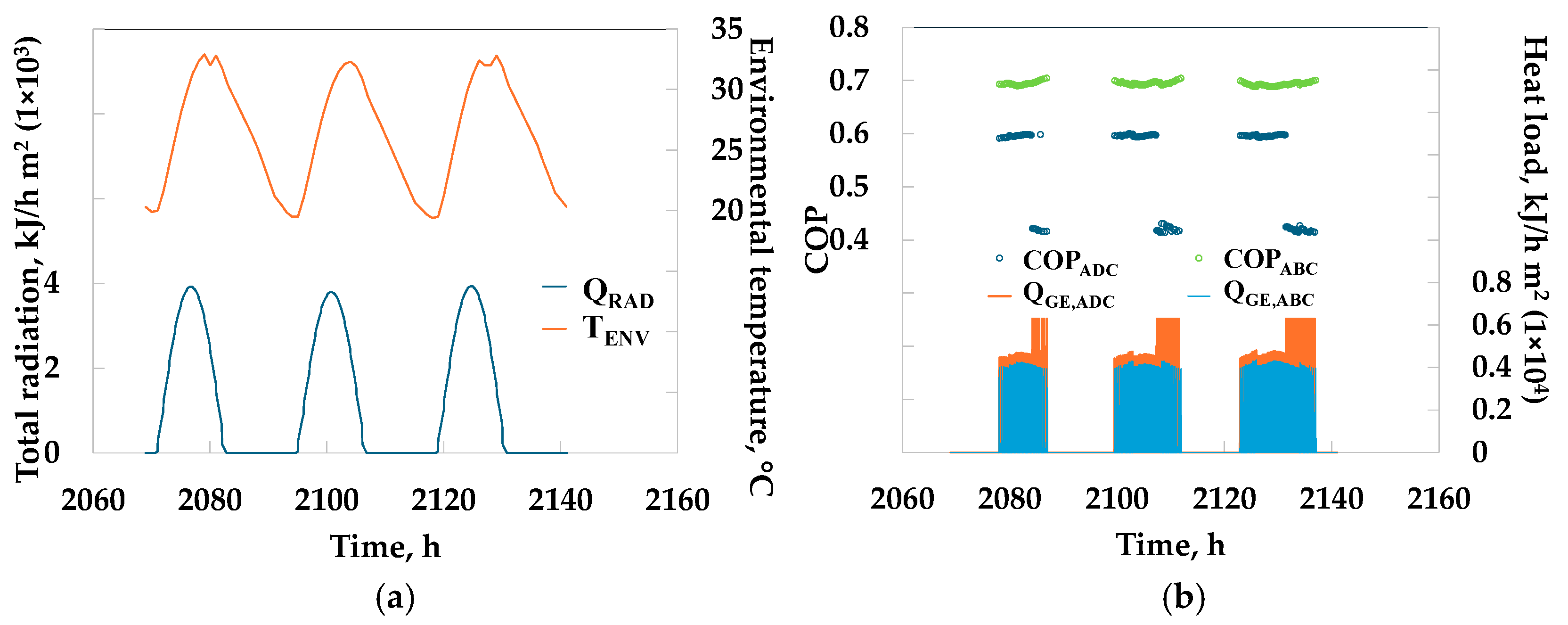
Three days of operation were selected (2069 to 2141 h) because they yielded good total horizontal radiation and corresponded to the hot season in Temixco, Morelos, Mexico, as shown in Figure 4a. Figure 4b shows the generator energy and COP of the sorption cooling systems at 20 m2 of ASC and 0.05 m of dth for MCHH. The COP remains almost constant for ABC at approximately 0.7 due to the short range of operation of the generator temperature, resulting in a generator energy of 5.50 × 10⁵ kJ. In contrast, the COP changes from 0.4 to 0.6 for the ADC, with an energy value of approximately 6.64 × 10⁵ kJ. The lowest value of COP for ADC occurs when the storage tank temperature reaches the minimum operating temperature (usually at the end of the day), and the heating system then turns on to maintain the minimum operational temperature (65 °C).
The initial conditions of the LHST were a temperature of 115 and 117 °C for MCHH and ERY, respectively, a solar collector tilt angle of 7° (optimized value), and Δt = 180 s for the simulation time step. The parametric analysis consisted of evaluating ASC at 10 to 30 m2 and 5 to 20 m2, for ET and PT, respectively, and 0.05, 0.10, and 0.15 m of dth.
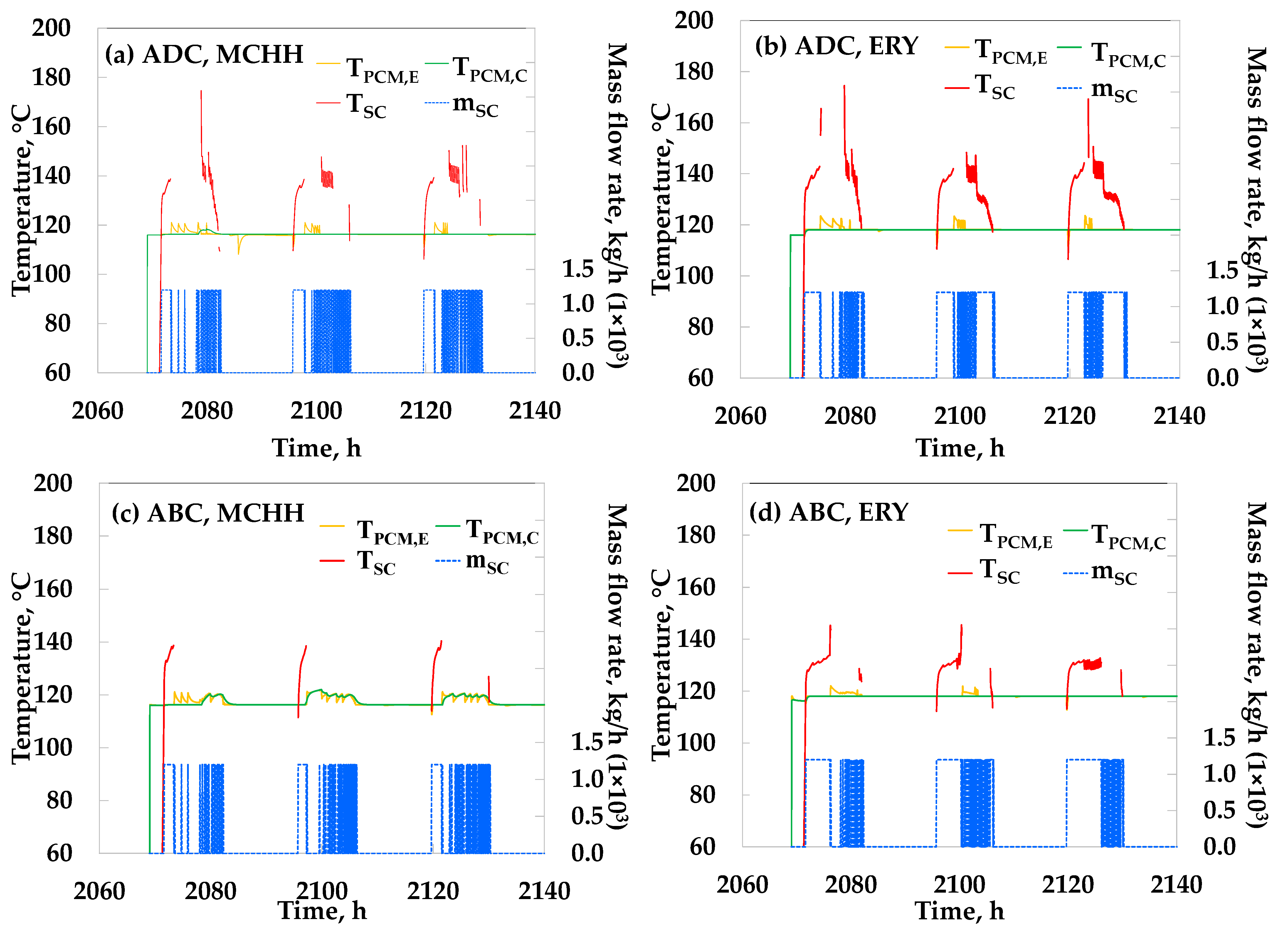
Figure 5 shows the behavior of the solar collector temperature (TSC) at the central (TPCM,C) and edge (TPCM,E) locations of the PCMs, as well as the mass flow rate of the solar collector (mSC) for the sorption systems, with an ASC of 20 m2. It can be observed that the solar collector system operates longer with ERY because the PCM retains more energy. Consequently, the LHST should be prevented from exceeding the maximum allowable temperature limits. The four systems illustrate how the PCM remains in a phase change state over the three days evaluated (with almost constant temperature), which prevents the reduction of supercooling during the night.
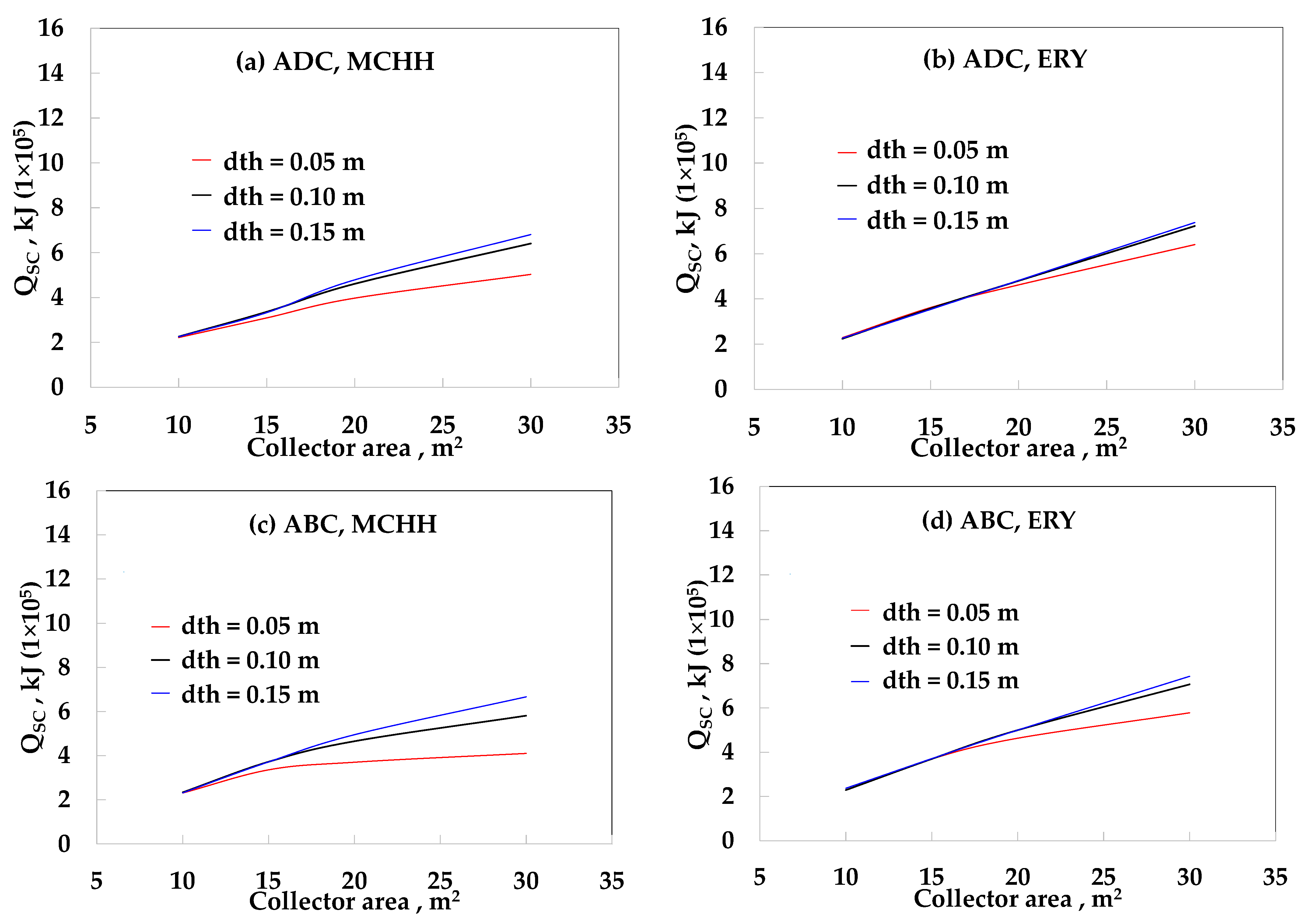
Figure 6 shows the solar collector energy (QSC) as a function of ASC using evacuated tubes from 10 to 30 m2 at different PCMs and sorption cooling systems. The minimum values of QSC were approximately 2.50 × 10⁵ kJ with an ASC of 10 m2 for all systems. The maximum values were around 6.81 × 10⁵ and 7.4 × 10⁵ kJ for MCHH and ERY, respectively, with a dth of 0.15 m and an ASC of 30 m2 in both sorption systems. This means that it is the maximum amount of solar energy that can be obtained by the ET.
Figure 7 shows the QSC as a function of solar area collector using a PT at different PCMs and sorption cooling. The system ADC-MCHH (Figure 7a) and ADC-ERY (Figure 7b) obtained QSC maximum values of 9.96 × 10⁵ and 10.60 × 10⁵ kJ, respectively, with a dth of 0.15 m with 20 m2 of ASC. ERY obtained higher QSC values than MCHH because it has sufficient capacity to absorb the heat supplied by the solar collector.
The ABC-MCHH (Figure 7c) system has QSC values from 4.88 × 10⁵ to 7.89 × 10⁵ and 5.41 × 10⁵ to 8.69 × 10⁵ kJ from 10 to 20 m2 of ASC with dth of 0.05 and 0.15 m, respectively. The ABC-ERY system (Figure 7d) is evaluated from 10 to 13 m2 of ASC, since a solar fraction above 0.96 is obtained (as seen later), the QSC values range from 5.40 × 10⁵ to 6.40 × 10⁵ for a dth of 0.05 m, and 5.40 × 10⁵ to 6.98 × 10⁵ kJ for dth of 0.10 and 0.15 m, respectively.
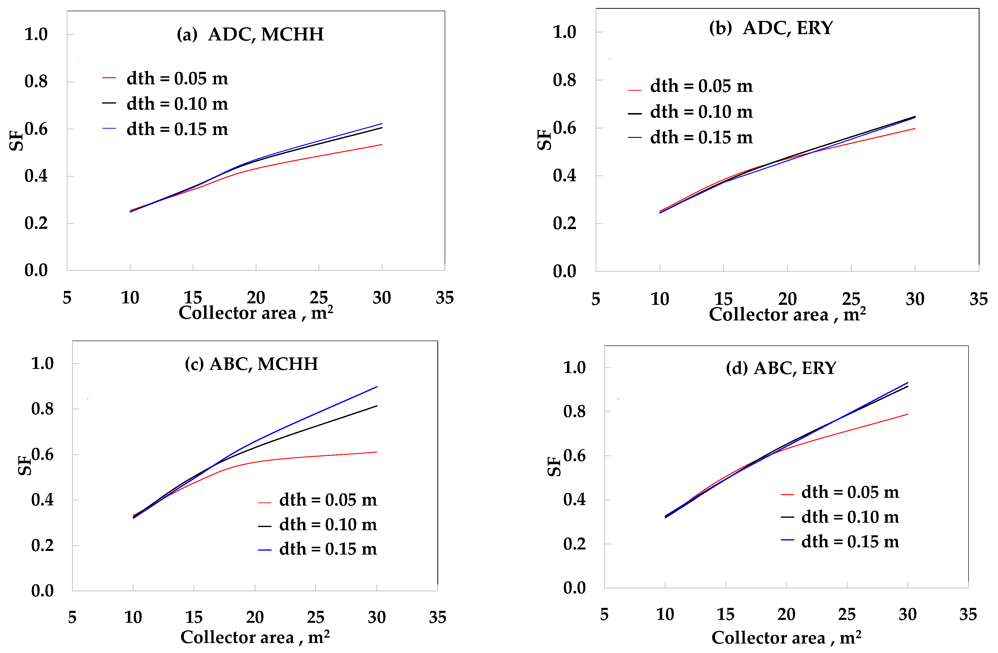
Figure 8 compares the solar fraction as a function of the solar collector area for ET with different dth and PCMs, as well as sorption systems. The solar fraction is defined as the ratio of solar energy-to-the total energy from both the solar and heating systems. The ADC-MCHH and ADC-ERY system (Figure 8a,b) obtained a similar value of SF of 0.25 with an ASC of 10 m2 for all the dth, while the maximum SF was 0.62 and 0.64 for MCHH and ERY, respectively, with a dth of 0.15 m and ASC of 30 m2.
The SF of the ABC systems (Figure 8c,d) had a maximum value of 0.61 and 0.79 for MCHH and ERY, respectively, with a dth of 0.05 m and an ASC of 10 m2. In contrast, the maximum SF was 0.90 and 0.93 for MCHH and ERY, respectively, with a dth of 0.15 m and an ASC of 30 m2. It can be observed that ERY obtained slightly better SF than MCHH.
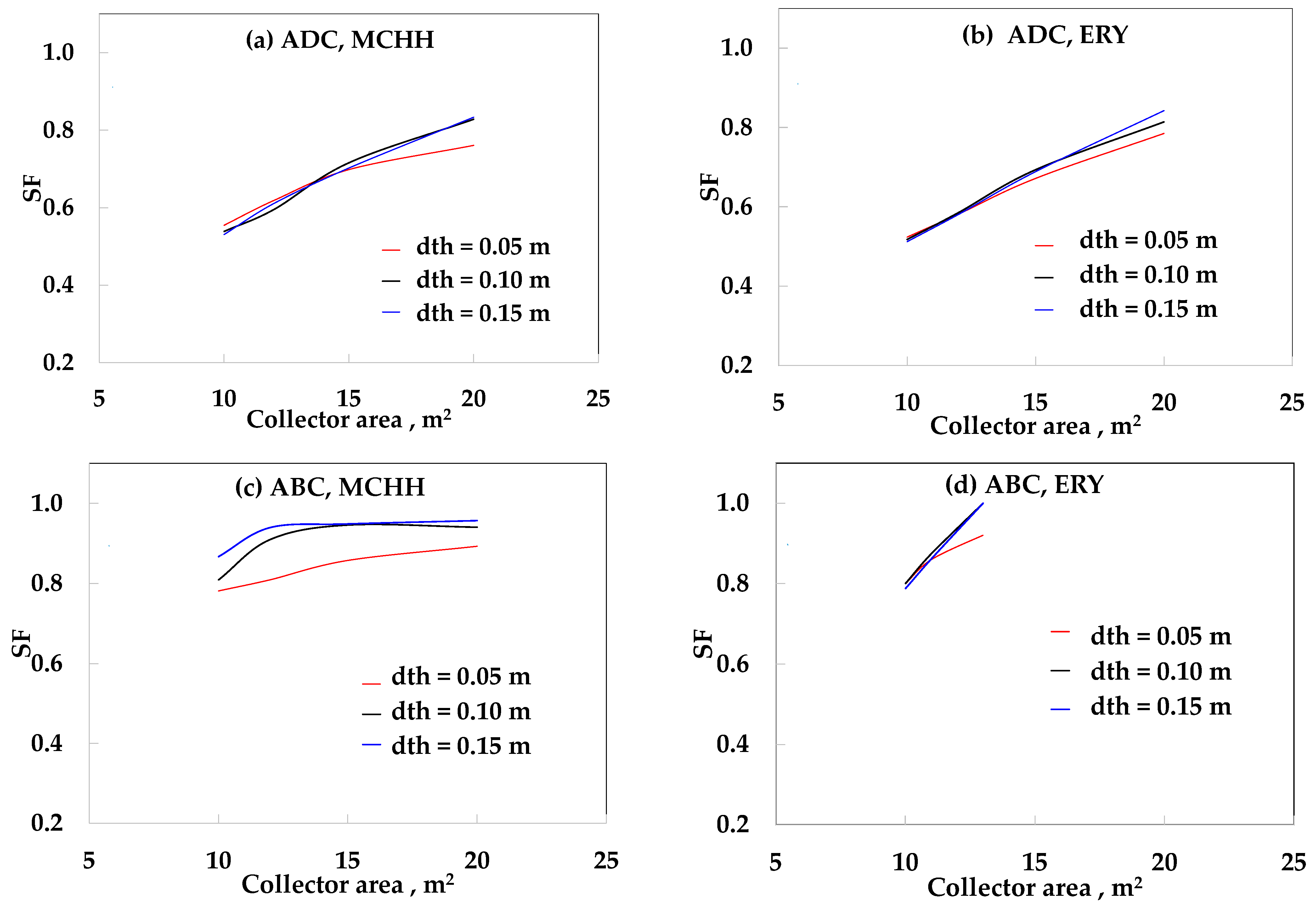
Figure 9 shows the solar fraction as a function of the solar collector area for parabolic trough collectors at different thicknesses of PCMs and sorption systems. The ADC-MCHH (Figure 9a) obtained an SF value from 0.55 to 0.76 and 0.53 to 0.83 for a dth of 0.05 and 0.15 m, respectively, from ASC of 10 to 20 m2. The ADC-ERY (Figure 9b) obtained a value of 0.51 to 0.78, and 0.51 to 0.84, for dth with 0.05 and 0.15 m from 10 to 20 m2 of ASC, respectively, In the ABC-MCHH system (Figure 9c), it is shown that the SF does not reach 1 at values above 13 m2 with dth of 0.10 and 0.15 m as ASC is incremented, because despite the solar collector energy is increasing (Figure 7c), the heater system almost obtained similar values (from 1.04 × 10⁴ to 3.91 × 10⁴ kJ with ASC from 12 to 20 m2), this means the heat dissipation in the PCM is very poor, and the energy is kept in the LHST, while the ABC-ERY system (Figure 9d) does reach a value of 1 with ASC of 13 m2 with 0.15 m.
Table 5 presents a summary of the maximum values of solar fraction at different dth with an ASC of 20 and 30 m2 for PT and ET, respectively, except for the ABC-PT-ERY system (ASC of 13 m2). The minimum and maximum values of SFMAX were for the ADC-ET-MCHH (0.53) and ABC-PT-ERY (1.0) systems, respectively. When the systems are compared under similar conditions, in general, the ABC obtained a better SFMAX than the ADC system, ERY obtained a better SFMAX than MCHH, and PT obtained better results than ET, despite using less ASC.
Figure 10 shows the effectiveness of the LHST as a function of time for the ABC-ERY and ABC-MCHH systems with a dth of 0.10 m and an ASC of 13 m2. This parameter was estimated using instantaneous temperature, and it was defined as the ratio of the actual heat transfer rate-to-the maximum possible. The effectiveness is in discharge mode (εDISCH) and is calculated when only the pump of the storage tank is turned on and enters the LHST, and the pump of the ABC is turned off. The εDISCH obtained an average value of 0.56 in both systems.

4. Discussion

The results indicate that ERY exhibits a higher energy storage capacity, accumulating 27,790 kJ over 180 min, compared to MCHH, which stores 21,700 kJ in 100 min. This is primarily due to ERY’s higher heat of fusion (337.0 kJ/kg) compared to MCHH (166.9 kJ/kg). However, ERY’s lower thermal conductivity results in slower heat dissipation. This characteristic could limit the ERY in applications requiring rapid thermal response. Conversely, MCHH’s higher thermal conductivity (in liquid phase) facilitates a slightly faster phase change dynamic, making it more suitable for systems with high transient thermal demands. The selection of PCM should thus be aligned with operational requirements, the ERY for maximizing energy storage, and MCHH for applications prioritizing rapid heat transfer. The results obtained for this investigation showed similar effectiveness in both PCMs, and the performance of the ERY obtained good results in the SF.
Increasing the dth from 0.05 m to 0.15 m enhances the energy storage capacity but exacerbates heat transfer limitations in ERY due to its low thermal conductivity. This suggests that thicker PCM layers are beneficial for maximizing storage but require enhanced heat transfer mechanisms, such as fins or composite PCMs, to improve thermal response in ERY-based systems. The optimal PCM thickness should strike a balance between storage capacity and heat transfer efficiency to maximize system performance.
The ABC system maintains a stable COP of approximately 0.70, while the ADC system’s COP fluctuates between 0.40 and 0.60. This variability in ADC performance is attributed to its lower activation temperature range (65–95 °C) compared to ABC (108.9–116.1 °C), which necessitates auxiliary heating when storage tank temperatures drop below operational thresholds, particularly during periods of low solar input. The ABC system’s consistent COP reflects its suitability for stable cooling demands but requires high-temperature solar collectors, potentially increasing capital costs. In contrast, ADC systems benefit from compatibility with simpler collectors, such as ET, but their reliance on auxiliary systems reduces overall efficiency. This highlights a critical trade-off between operational simplicity and thermal efficiency, necessitating further analysis to optimize system design for specific applications.

5. Conclusions

This work shows an analysis of adsorption and ABC systems using parabolic trough and evacuated tube solar collectors coupled to a rectangular LHST with MCHH and ERY in dynamic conditions, as evaluated using TRNSYS software over three days. The following conclusions were drawn.
A simulation of the LHST was performed, yielding a total energy of 27,790 kJ in 180 min with ERY and 21,700 kJ in 100 min with MCHH, respectively. The energy consumed includes latent and sensible heat with a thickness of 0.05 m.
The operation time of the solar energy collector was higher for ADC than for ABC because the temperature of the LHST was lower due to ADC’s higher energy consumption, so the pump was turned on for a longer period.
The maximum QSC (with ET) was around 6.81 × 10⁵ and 7.4 × 10⁵ kJ for MCHH and ERY, respectively, with a dth of 0.15 m and an ASC of 30 m2.
The maximum QSC (with PT) was 9.96 × 10⁵ and 10.60 × 10⁵ kJ for ADC-MCHH and ADC-ERY systems with a dth of 0.15 m and ASC of 20 m2, respectively. The system ABC-MCHH obtained a maximum QSC of 8.69 × 10⁵ kJ with dth of 0.15 m and an ASC of 20 m2, and ABC-ERY obtained a maximum value of 6.98 × 10⁵ kJ with dth of 0.15 m and an ASC of 13 m2.
The maximum SF (with ET) was 0.62 and 0.64 for the ADC-MCHH and ADC-ERY systems, respectively, with a dth of 0.15 m and an ASC of 30 m2, while with absorption cooling, higher SF values of 0.90 and 0.93 for MCHH and ERY, respectively, were obtained at similar conditions.
The maximum SF (with PT) was 0.83 and 0.84 for ADC-MCHH and ADC-ERY systems, respectively, with a dth of 0.15 m and ASC of 20 m2. The ABC-MCHH system obtained values higher than 0.95 above ASC of 13 m2; however, it did not reach a value of 1 at higher ASC, because the heat dissipation in the PCM is very poor and the energy is retained in the LHST. The ABC-ERY system did reach a value of 1 with ASC of 13 m2 with 0.15 m.
The control system of the LHST limited the solar energy harvesting time due to the temperature difference between the center and the edge of the PCM, which could fall under supercooling conditions; therefore, the application of advanced heat transfer techniques is important.
The SF of the evacuated tube solar collectors would be improved by using another PCM with a lower melting point for the adsorption cooling.
Erythritol was able to meet the energy requirements only with solar collectors due to its high energy density; however, the cost per kilogram was 44 times higher than MCHH, and it exhibited a reduction in latent heat after a few thermal cycles. A deep study should be conducted for ERY, including an economic analysis.

Author Contributions

Conceptualization, J.C.; methodology, J.C. and R.J.R.; software, J.C.; validation, E.V.-R. and J.C.; formal analysis, J.C. and R.J.R.; investigation, J.C.; data curation, F.L. and E.V.-R.; writing—original draft preparation, J.C., R.J.R., F.L. and E.V.-R.; writing—review and editing, E.V.-R. and M.M.-G.; visualization, J.C. and M.M.-G.; supervision, J.C. All authors have read and agreed to the published version of the manuscript.

Funding

This research received no external funding.

Data Availability Statement

The original contributions presented in this study are included in the article material. Further inquiries can be directed to the corresponding author.

Conflicts of Interest

The authors declare no conflicts of interest.

Abbreviations

The following abbreviations are used in this manuscript:
AArea
ABCAbsorption cooling
ADCAdsorption cooling
COPCoefficient of operation
ERYErythritol
edEnergy density, kJ/m3
DISCHDischarge
dthThickness of the PCM, m
F′(τα)Collector (F′) (transmittance) (absorptance) product
hEnthalpy, kJ/kg
HFHeating fluid
htcHeat transfer coefficient, kW/m2 °C
kThermal conductivity, kW/m °C
LHSTLatent heat storage tank
mMass flow rate,
MCHHMagnesium chloride hexahydrate
PCMPhase change material
QEnergy, kJ
TTemperature, °C
tTime, s
Subscript
SCSolar collector
LLiquid
SSolid
Greek letter
εEffectiveness
αThermal diffusivity, m2/s

References

  1. Al-Falahi, A.; Alobaid, F.; Epple, B. Thermo-Economic Comparisons of Environmentally Friendly Solar Assisted Absorption Air Conditioning Systems. Appl. Sci. 2021, 11, 2442. [Google Scholar] [CrossRef]
  2. Al-Alili, Y.; Hwang, Y.; Radermacher, R. Review of solar thermal air conditioning technologies. Int. J. Refrig. 2014, 39, 4–22. [Google Scholar] [CrossRef]
  3. Fan, Z.; Infante, C.A.; Mosaffa, A.H. Numerical modelling of high temperature latent heat thermal storage for solar application combining with double-effect H2O/LiBr absorption refrigeration system. Sol. Energy 2014, 110, 398–409. [Google Scholar] [CrossRef]
  4. Pintaldi, S.; Sethuvenkatraman, S.; White, S.; Rosengarten, G. Energetic evaluation of thermal energy storage options for high efficiency solar cooling systems. Appl. Energy 2017, 188, 160–177. [Google Scholar] [CrossRef]
  5. Zhou, L.; Li, X.; Zhao, Y.; Dai, Y. Performance assessment of a single/double hybrid effect absorption cooling system driven by linear Fresnel solar collectors with latent thermal storage. Sol. Energy 2017, 151, 82–94. [Google Scholar] [CrossRef]
  6. Cerezo, J.; Lara, F.; Romero, R.J.; Rodríguez, A. Analysis and Simulation of an Absorption Cooling System Using a Latent Heat Storage Tank and a Tempering Valve. Energies 2021, 14, 1376. [Google Scholar] [CrossRef]
  7. Mehmood, S.; Lizana, J.; Friedrich, D. Solar-Driven Absorption Cooling System with Latent Heat Storage for Extremely Hot Climates. Energy Convers. Manag. 2023, 297, 117737. [Google Scholar] [CrossRef]
  8. Migla, L.; Bogdanovics, R.; Lebedeva, K. Performance Improvement of a Solar-Assisted Absorption Cooling System Integrated with Latent Heat Thermal Energy Storage. Energies 2023, 16, 5307. [Google Scholar] [CrossRef]
  9. Hosseini, L. Desing and Analysis of a Solar Assisted Absorption Cooling System Integrated with Latent Heat Storage. Master’s Thesis, Delft Universisty of Technology, Delft, The Nederlands, 2011. [Google Scholar]
  10. Poshtiri, A.H.; Jafari, A. 24-hour cooling of a building by a PCM-integrated adsorption system. Int. J. Refrig. 2017, 79, 57–75. [Google Scholar] [CrossRef]
  11. Kuczyńska, A.; Szaflik, W. Absorption and adsorption chillers applied to air conditioning systems. Arch. Thermodyn. 2010, 31, 77–94. [Google Scholar] [CrossRef]
  12. A Transient System Simulation Program, Solar Energy Laboratory. TRNSYS 18. Available online: http://sel.me.wisc.edu/trnsys/ (accessed on 1 July 2025).
  13. Solar Energy Laboratory. Multi-zone Building Modeling with Type 56 and TRNBuild, TRNSYS 16, Volume 6; University of Wisconsin: Madison, WI, USA, 2007; Available online: https://web.mit.edu/parmstr/Public/Documentation/06-MultizoneBuilding.pdf (accessed on 1 July 2025).
  14. TESS-Thermal Energy Systems Specialists. HVAC Library Mathematical Reference, TESSLibs 17, TRNSYS 17, Volume 6; TESS–Thermal Energy Systems Specialists: Madison, WI, USA, 2014. [Google Scholar]
  15. Solar Energy Laboratory. Mathematical Reference, TRNSYS 16, Volume 5; University of Wisconsin: Madison, WI, USA, 2006. Available online: https://web.mit.edu/parmstr/Public/Documentation/05-MathematicalReference.pdf (accessed on 1 July 2025).
  16. Solar Rating & Certification Corporation. Technical Data. Solar Concentration Model LH-3-2M. 2018. Available online: https://solar-rating.org/ (accessed on 1 July 2021).
  17. Solar Rating & Certification Corporation. Directory of SRCC Certified Solar Collector Ratings; Solar Rating & Certification Corporation: Washington, DC, USA, 2009. [Google Scholar]
  18. Klein, S.A. EES, Engineering Equation Solver; Professional Version; FChart Software: Madison, WI, USA, 2017; Available online: https://www.fchart.com/ees/ (accessed on 1 July 2025).
  19. Höhlein, S.; König-Haagen, A.; Brüggemann, D. Thermophysical Characterization of MgCl2·6H2O, Xylitol and Erythritol as Phase Change Materials (PCM) for Latent Heat Thermal Energy Storage (LHTES). Materials 2017, 10, 444. [Google Scholar] [CrossRef] [PubMed]
  20. Sigma-Aldrich. Available online: https://www.sigmaaldrich.com (accessed on 1 July 2025).
  21. El-Sebaii, A.A.; Al-Heniti, S.; Al-Agel, F.; Al-Ghamdi, A.A.; Al-Marzouki, F. One thousand thermal cycles of magnesium chloride hexahydrate as a promising PCM for indoor solar cooking. Energy Convers. Manag. 2011, 52, 1771–1777. [Google Scholar]
  22. Agyenim, F.; Eames, P.; Smyth, M. Experimental study on the melting and solidification behaviour of a medium temperature phase change storage material (Erythritol) system augmented with fins to power a LiBr/H2O absorption cooling system. Renew. Energy 2011, 36, 108–117. [Google Scholar] [CrossRef]
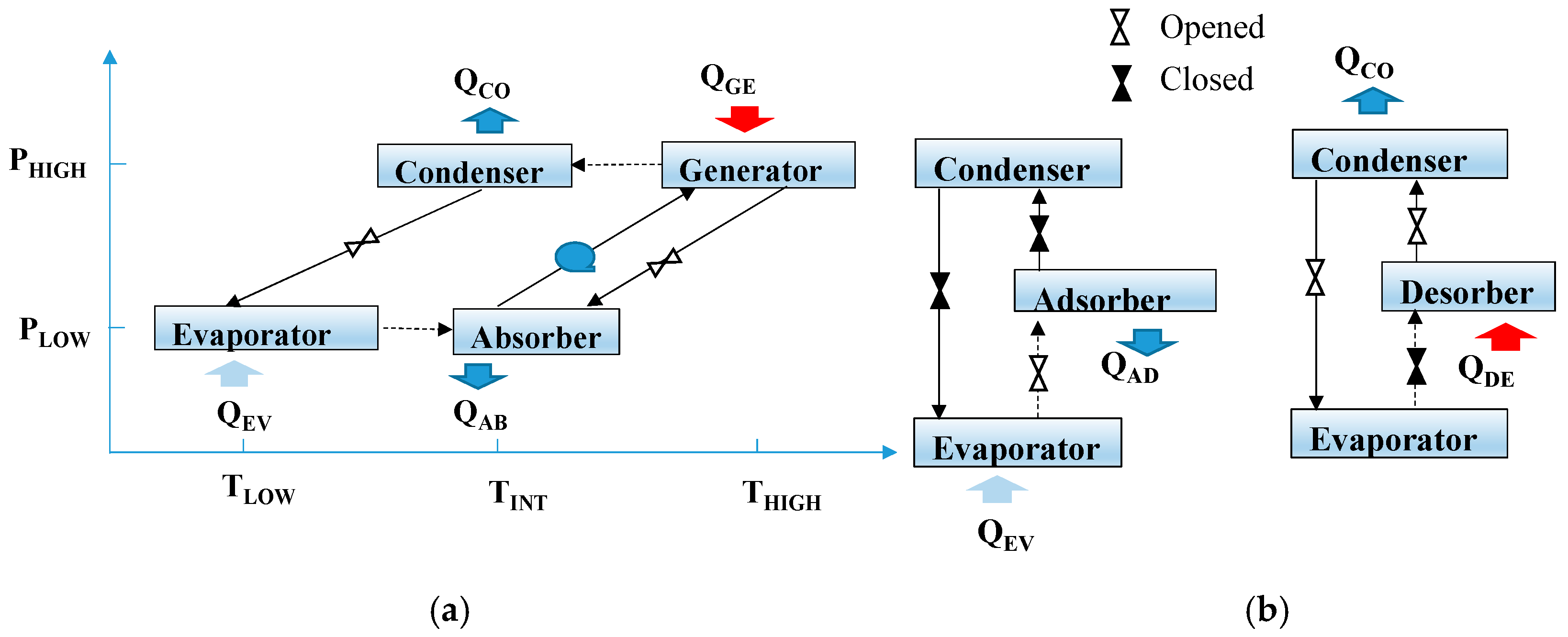
Figure 1. Schematic diagram of (a) single-stage absorption, (b) adsorption/desorption phases of an adsorption cycle.
Processes 13 02655 g001
Figure 2. Schematic of the absorption cooling system.
Processes 13 02655 g002
Figure 3. Energy of the LHST in one of the central channels of the heating fluid.
Processes 13 02655 g003
Figure 4. (a) Radiation and environmental temperature of Temixco city and (b) COP and generator heat load of the sorption cooling systems.
Processes 13 02655 g004
Figure 5. Thermal behavior as a function of time for MCHH with a thickness of 0.05 m.
Processes 13 02655 g005
Figure 6. Energy of the solar collector as a function of the area of the evacuated tube collector for different sorption systems, PCMs, and thicknesses.
Processes 13 02655 g006
Figure 7. Solar collector energy as a function of the area of the PT for different sorption systems, PCMs, and thicknesses.
Processes 13 02655 g007
Figure 8. Solar fraction as a function of the area of the ET for different sorption systems, PCMs, and thicknesses.
Processes 13 02655 g008
Figure 9. Solar fraction as a function of the area of the PT for different sorption systems, PCMs, and thicknesses.
Processes 13 02655 g009
Figure 10. Effectiveness as a function of the time using PT.
Processes 13 02655 g010
Table 1. Range of operation of the sorption cooling systems.
ComponentTSET (°C)TCHILLED (°C)TCOOLING (°C)TGE (°C)
ABC6.75.5–10.026.6–32.2108.9–116.1
ADC6.75.0–12.010.0–35.065.0–95.0
Table 2. Description of the type used in TRNSYS software.
ComponentTypeDescription
Parabolic trough collector 1288This subroutine models a concentrating solar collector. The efficiency parameters for the PT are F′(τα) = 0.611, C1 = 1.42, C2 = 0.021, C3 = 0.0, C4 = 0.0, C5 = 6.653, C6 = 0.0 [16].
Evacuated tube collector71Intercept efficiency = 0.418; Negative first-order efficiency coefficient = 4.212 kJ/h m2 K [17].
Weather data15-2The weather data processor reads data at regular intervals from an external weather data file, interpolates it at time steps of less than one hour, and provides the processed data to other TRNSYS components. Meteorological data were used for Temixco, Mexico.
Heating system6This component increases the temperature of a flow stream using either internal or external control. Data provided: Overall heat coefficient = 2.58 kJ/h m2 K, efficiency = 0.98.
Heat dissipater92This component reduces the temperature of a flow stream using either internal or external control. Data provided: Overall heat coefficient = 2.58 kJ/h m2 K, efficiency = 0.98.
Cooling tower510“This type models a closed-circuit cooling tower. A closed-loop evaporative cooler that removes heat from a liquid stream by evaporating water over coils, with the working fluid fully isolated from air and water contact”.
C1 and C32bThis component is an on/off differential controller that switches off or on when it has a value of 0 or 1, depending on the upper and lower temperature differences, as well as the dead-band temperature differences.
C21503This models three ON/OFF control functions to control a fluid cooling system.
P1, P2, P3, P43dThis component computes a mass flow rate using a variable control function. Data provided: Conversion coefficient = 0.05.
Table 3. Properties used for PCM.
ComponentTmelting
(°C)
Heat
Fusion (kJ/kg)
Cp
(kJ/kg °C)
k
(W/m K)
p (kg/m3)Thermal
Diffusivity
(m2/s, 1 × 10⁴)
Energy
Density
(kJ/m3)
ERY118.1337cpS = 1.34 (20 °C)
cpL = 2.87 (150 °C)
kS = 0.89 (20 °C)
kL = 0.33 (140 °C)
p S = 1440.4 (20 °C)
p L = 1289.1
αS = 4.61
αL = 0.89
edS = 0.234
edL = 0.261
MCHH115.1–117.4166.9cpS = 1.83 (100 °C)
cpL = 2.57 (120 °C)
kS = 0.70 (110 °C)
kL = 0.63 (120 °C)
p S = 1595.5 (20 °C)
p L = 1455.7
αS = 2.39
αL = 1.6
edS = 0.105
edL = 0.115
Table 4. Operating conditions and size of the LHST.
ParameterValue
PCM Thickness (dth), m0.05
Total flow rate of heating fluid, kg/s0.55
Wide channel, m8.99
Height channel, m0.005
Longitude channel, m0.16
Isolation, m0.10
Table 5. Maximum values of solar fraction for each system.
CaseSFMAX
(dth = 0.05 m)
SFMAX
(dth = 0.10 m)
SFMAX
(dth = 0.15 m)
ADC-ET-MCHH0.530.610.62
ADC-ET-ERY0.600.640.64
ADC-PT-MCHH0.760.830.83
ADC-PT-ERY0.780.810.84
ABC-ET-MCHH0.610.810.90
ABC-ET-ERY0.790.920.93
ABC-PT-MCHH0.890.940.96
ABC-PT-ERY0.921.001.00
Disclaimer/Publisher’s Note: The statements, opinions and data contained in all publications are solely those of the individual author(s) and contributor(s) and not of MDPI and/or the editor(s). MDPI and/or the editor(s) disclaim responsibility for any injury to people or property resulting from any ideas, methods, instructions or products referred to in the content.