Abstract
The perforating–fracturing–testing combined technology has emerged as a crucial well completion technique to enhance production efficiency. However, the shock loads generated during perforation in the packed section of an oil and gas well significantly affect the stability of the perforating tubing string system, potentially leading to deformation or even fracture. During the perforating operation, a large amount of blast products is generated, and as these products escape the perforating gun and interact with the perforating fluid, the fluid pressure pulsates. These pressure fluctuations are the primary cause of the dynamic response of the perforating tubing string. The greatest threat to tubing string integrity occurs when pulsating pressure reaches its peak amplitude, potentially leading to tubing failure. To address this, this study employs underwater explosion theory to analyze the pressure variations during the generation and propagation of shock waves in perforation operations. Additionally, quantitative numerical simulation analysis reveals key relationships governing peak perforating fluid pressure: peak pressure remains remarkably stable at 370–371 MPa despite variations in perforating fluid viscosity (0–110 cP) or tubing Young’s modulus (100–260 GPa). However, it responds significantly to other parameters: fluid density (1–3 g/cm3) causes a linear increase from 335 MPa to 598 MPa; total charge mass drives a proportional rise from 162 MPa to 388 MPa; detonation interval (0–50 μs) elevates pressure from 268 MPa to 378 MPa; and formation pressure (0–100 MPa) increases it from 315 MPa to 372 MPa. Crucially, peak pressure decreases from 376 MPa to 243 MPa as the explosion space expands (0–5 m3). Furthermore, a nonlinear regression model is developed to predict peak perforating shock loads. The results indicate that residual perforation energy critically impacts tubing string safety. Validated against two field cases, the model achieves nearly 10% error compared to predictions from Pulsfrac (industry-standard perforating shock software), meeting field requirements while providing actionable insights for wellbore integrity and perforating tubing string stability.
1. Introduction
In oil and gas field operations, perforation frequently induces various challenges, including formation damage, monitoring equipment impairment, compressive failure of tubing joints, perforating gun disconnection, firing head bending, wireline weak-point failure, tubing string plastic deformation, and accidental tool release [1,2,3,4,5,6], as shown in Figure 1. For instance, a shear failure of the firing head during perforation in the Manati 1 well (Camamu Basin, Brazil) resulted in tubing string detachment [7]. The growing application of perforation in deep and ultra-deep wells, driven by China’s ‘Toward the Deep Earth’ energy development strategy, alongside widespread adoption of combined perforating–fracturing operations to enhance efficiency, underscores the critical need for safe perforation practice. Perforating tubing string failure and subsequent wellbore obstruction inevitably disrupt subsequent operations, ultimately impeding the daily hydrocarbon production.
Figure 1.
Schematic diagram of perforating operation.
Recent research has focused on understanding perforating shock loads through theoretical and simulation approaches. Beginning in 1997, Carlos Baumann et al. pioneered a high-accuracy finite element method based on the discontinuous Galerkin method to model fluid-dynamics convection-diffusion. By developing corresponding perforating shock loads predicting software, they enabled the forecasting of downhole transient pressure waves and structural loads during perforation. Their work systematically established that tubing length and casing pressure differential significantly influence shock loads, providing a foundational framework for optimizing perforation parameters [8,9,10,11].
In 2004, Schatz et al. developed a numerical model validated against field-measured data to investigate perforation detonation load effects on tubing string dynamic response in deepwater environments. This model accurately simulates complex fluid-structure interactions in downhole components during perforation operations and effectively predicts operational failure modes [3]. Subsequently, in 2010, Antonio Canal et al. employed a finite difference method to develop a detonation shockwave modeling program. This advancement enabled rigorous analysis of shock loads impacting wellbore equipment safety during completion perforations, ultimately reducing non-productive time while maximizing hydrocarbon well productivity [7]. In 2011, William Sanders et al. developed a pressure wave prediction model incorporating rapid-acquisition field data and leveraging extensive wellbore pressure modeling expertise. Their analysis demonstrated the critical influence of perforating tubing string mass and stiffness on axial force distribution [12].
In 2014, Brinsden et al. established a high-speed, high-accuracy numerical model to predict shock damage risk in perforating tubing string for shock loads mitigation. Their research elucidated the synergistic mechanism between internal pressure waves and fluid motion under both dynamic underbalanced and overbalanced conditions [13]. Concurrently, Bale et al. investigated the shock load effects on tubular vibration through enhanced perforation modeling software. By refining thermodynamic modules and numerical evolution algorithms, alongside designing four Riemann-problem pressure analyses, they quantified explosive energy conversion efficiency: 30% transformed into fluid internal energy under strong shock conditions versus merely 10% under weak shock conditions. This efficiency differential correlates with observed failure modes in explosive-load scenarios [14]. Complementing these efforts, Gilliat et al. optimized dynamic perforation modeling software to precisely predict spatial loads on completion strings. Their improvements included advanced pressure equation solvers and explicit integration of downhole tool friction effects, enabling accurate simulation of wave superposition phenomena that induce tubing string failure patterns [5].
In 2017, Magri et al. numerically confirmed that underbalanced perforation operations induced significant packer annular pressure differentials. Their analysis demonstrated that optimized perforating charge arrangement or increased packer-gun distance can markedly attenuate tensile forces within completion strings [15]. Concurrently, Liu et al. established a sophisticated axial–lateral–torsional coupled nonlinear dynamic model of tubular systems based on Hamilton’s principle. With particular emphasis on perforating detonation loads, their investigation examined the influence mechanisms of key perforation parameters on tubular shock vibrations, demonstrating that shock absorber placement effectively mitigates dynamic stress within tubing strings [16].
However, existing research exhibits limited predictive capability regarding perforating shock loads, with predominant reliance on qualitative analyses, theoretical derivations, or finite element simulations. The mathematical relationships governing downhole environmental conditions in the packed section of oil and gas wells, perforating parameters, and resultant shock loads remain systematically unquantified.
This study aims to address these gaps by analyzing the generation mechanism and propagation characteristics of perforating shock loads based on the theory of underwater explosion to identify the hazards of shock loads on downhole equipment in advance, such as perforating tubing string under different conditions. This study also models and simulates the perforating tubing string system according to actual field conditions. Additionally, the orthogonal experiments are conducted for five factors: charge mass, wellbore initial pressure, wellbore explosion space, detonation interval, and formation pressure. Finally, a prediction model of peak perforating shock load in oil and gas wells is developed. Finally, using actual construction data from two wells in the fields of southwestern China, the model obtained from this study is compared with commercial perforation software, providing a valuable reference for predicting perforation risks in the field.
2. Output Characteristics of Shock Loads
2.1. Generation Mechanism of Shock Load
The generation of a shock wave during perforation is due to the disturbance of the perforating fluid when the charges detonate. Given the time required for this disturbance to propagate in each part of the fluid and considering the fluid is contained within the narrow and elongated confined section of the wellbore, it becomes challenging to maintain a uniform velocity of the fluid in each part of the fluid during the perforation. Therefore, according to the velocity, the shock waves generated in the perforating fluid are divided into the micro-amplitude wave, in which the physical quantities are continuous before and after the wavefront interface and the finite amplitude wave, such that the physical quantities are jumping before and after the wavefront interface.
When charges detonate in a uniform and static perforating fluid, high-temperature and high-pressure explosive gas is produced, which expands dramatically outward. During this expansion, the temperature and pressure of the fluid rise sharply in a very short period, ultimately forming a shock wave. This shock wave manifests as a high-temperature and high-pressure surface that propagates rapidly through the perforating fluid in the downhole packed section, causing a sudden jump at the discontinuity surface, as illustrated in Figure 2.
Figure 2.
Shock waves in fluids.
2.2. Propagation and Output of Loads
The asymmetric shock loads generated by explosive perforation initially impact the perforating gun and subsequently propagate to downhole equipment, including packers and tubing. This induces substantial axial and radial vibrations within the tubing string system. Concurrently, these shock loads propagate as pressure waves through the wellbore fluid, inducing considerable deformation and pressure fluctuations within the annular fluid over a brief period. As the waves propagate, they undergo multiple complex reflections and transmissions at the interfaces between the tubing and casing walls, as illustrated in Figure 3. Ultimately, this dynamic wave activity can excite significant vibrational responses in the tubing, posing a potential risk to the overall stability and structural integrity of the tubing system.
Figure 3.
Schematic diagram of detonation shock waves generation.
According to the theory of underwater explosions, shock waves propagating through water undergo attenuation. As the propagation distance increases, the wavefront velocity and pressure of the shock wave decrease rapidly, while the waveform gradually broadens. This pressure decay follows an exponential function of time, as experimentally derived by Cole [17], and satisfies the following equation:
where P is the shock wave pressure, P0 is the peak pressure, θ is the pressure duration, and t is the time.
Analysis of the above equation reveals that the pressure of underwater explosive shock waves attenuates rapidly over time, with the pronounced decay occurring proximal to the explosion source.
2.3. Energy Composition of Perforation
With the continuous advancement of perforation technology, charges have evolved from bullets to the widely adopted shaped charges. Upon detonation, these charges induce liner collapse, generating high-velocity metal jets that sequentially penetrate the casing, cement sheath, and formation. The structural configuration, explosive type, and charge mass directly govern perforation penetration efficiency and subsequent hydrocarbon productivity. Crucially, more energetic explosives employed in perforation can release approximately half of their energy as shock waves, establishing these waves as the dominant source of impact damage to the tubing string system. The shock waves generated during perforation primarily originate from the residual explosive energy released by the charges.
In practical applications, shaped charges achieve penetration depths exceeding 1 m and maximum diameters up to 20 mm. Owing to their high penetration capability and concentrated energy release, they are extensively utilized in perforating deepwater and deep-earth oil and gas wells [18,19,20]. Structurally, a shaped charge comprises primarily a liner and explosive material housed within a perforating gun, as shown in Figure 4.
Figure 4.
Schematic cross-section of the perforating gun.
The formation of a shaped charge jet constitutes a complex physicochemical process, generating localized overpressures of several hundred to over one thousand MPa within microseconds. As the jet penetrates the casing and formation, the charges release a portion of their energy into the wellbore. This released energy represents the source of wellbore safety hazards, its magnitude being dependent upon charge mass, perforating gun size, and other operational parameters. Crucially, excess residual energy present within the packed section of oil and gas wells during perforation constitutes the primary cause of tubing system integrity issues. This hazard is distinct from the effects of the jet itself and other energy dissipation mechanisms. Consequently, this study focuses exclusively on characterizing residual energy, explicitly excluding consideration of the jets and their penetration effects. The residual perforating energy is modeled as equivalent to an explosive charge of identical energy release, while neglecting other minor energy losses. The resultant shock load is thereby determined based on the known mass of the equivalent explosive charge.
3. Establishment and Accuracy Verification of Numerical Simulation Model
3.1. Geometric Model
Upon detonation of the shaped charge during perforation, the resultant high-velocity charge jet penetrates the perforating gun, casing, and cement sheath. This process simultaneously generates pressure waves within the perforating fluid that propagate to the tubing. Based on this physical phenomenon, the perforating tubing system is simplified to establish the 3D numerical simulation model depicted in Figure 5. The key model dimensions are as follows:
Figure 5.
Three-dimensional model of tubing string system.
Formation: Thickness 180 mm, length 10 m.
Tubing: OD 73.02 mm, ID 62.00 mm, length 20 m.
Perforating gun: OD 177.80 mm, ID 152.53 mm, length 10 m.
Casing: Outer diameter (OD) 244.40 mm, inner diameter (ID) 220.50 mm, length 40 m.
3.2. Material Constitutive Models and State Equations
For the numerical calculation of explosive mechanics within the model, the material properties of the tubing, perforating gun, and casing are defined, along with their respective boundary constraints. The Lagrange algorithm, selected for its precision in handling small deformations and tracking grid motion, is applied to these three components. For domains experiencing large deformations during perforation (perforating fluid, air, and explosives), the Arbitrary Lagrangian–Eulerian (ALE) algorithm is implemented. This algorithm permits mesh movement relative to the coordinate system, ensuring accurate simulation of the physical phenomena [21,22].
For the boundary conditions, constraints are applied to the top of the tubing to simulate the packer-induced casing restriction, while the casing is fully fixed to represent cement sheath immobilization. Meanwhile, a non-reflective boundary condition is applied at the tubing top to simulate stress wave propagation. Finally, formation pressure is applied to the casing–formation interface mesh, and an axial downward gravitational load is imposed throughout the entire model.
Given the prevalent use of high explosives in perforation operations, HMX is specified as the charge material. In LS-DYNA, detonation is modeled using the HIGH_EXPLOSIVE_BURN material model, which accurately simulates high-explosive detonation physics. The JWL (Jones–Wilkins–Lee) equation of state is employed to characterize the pressure–volume–energy relationship of the detonation products. The equation of state for the explosive is as follows:
where Pw is the explosive pressure; Vw is the volume of detonation products per unit volume of explosive charge; Ew is the internal energy per unit volume of explosion; and A1, A2, R1, R2, and ω1 are constants in the equation of state.
The parameters for HMX explosives are shown in Table 1:

Table 1.
Parameters of HMX explosives.
Meanwhile, the air is modeled using the MAT_NULL model, with the LINEAR_POLYNOMIAL equation of state defined as follows:
where C0–C6 are the coefficients of the equation of state, and μk is the density ratio. The parameters for air are provided in Table 2:
Table 2.
Parameters of air.
Additionally, the annular fluid is modeled using the MAT_NULL model, with the Gruneisen equation of state defined as follows:
where ρJ is the initial density of the medium; CJ is the intercept of the shock wave velocity curve; αJ is the medium’s compression coefficient; γ0 is a constant in the equation of state; δJ is the correction factor for the equation of state; and S1, S2, S3 are the slope coefficient of the stress wave velocity curve in the material.
The parameters for the perforating fluid are provided in Table 3:
Table 3.
Parameters of perforating fluid.
Finally, as the formation surrounds the outside of the casing, the casing is modeled using the Holmquist–Johnson–Cook model. The equation is as follows:
where fc is the uniaxial compressive strength; q1, q2 and q3 are material constants; P*N is the normalized pressure; q4 is the damage value of the formation; and ε* is the normalized strain rate.
The parameters of formation are shown in Table 4:
Table 4.
Parameters of formation.
3.3. Mesh Independence Verification
To ensure the numerical simulation accurately replicates the actual fluid pressure and stress wave propagation through the tubing string, the perforating tubing system model employs structured meshing as demonstrated in Figure 6. The discretized system model contains approximately 1.2 million nodes and 1 million elements; all element quality metrics, including aspect ratio, warpage, skew, and internal angles, are validated against prescribed tolerance thresholds.
Figure 6.
Schematic of the model mesh.
Mesh independence verification constitutes a critical step in validating numerical simulation accuracy. In finite element method simulations, mesh density exerts a significant influence on solution outcomes. While finer discretization generally improves accuracy, beyond a critical threshold, further mesh refinement yields diminishing returns in precision. Conversely, excessive mesh density substantially increases computational expense. Thus, optimizing element count while preserving solution accuracy is essential. To balance computational efficiency with solution fidelity, progressive mesh refinement is performed under consistent boundary conditions and loading. Mesh independence is subsequently determined by comparative analysis of solution convergence across refinement levels.
In this study, perforating shock load is characterized by perforating fluid pulsating pressure, which serves as the mesh independence criterion. As shown in Figure 7, fluid pulsating pressure exhibits a positive correlation with mesh density within the 1.4–1.9 million element range; the pulsating pressure of the fluid increases correspondingly with mesh density. However, beyond 1.9 million elements, further refinement produces negligible variation in pulsating pressure, indicating solution convergence. Consequently, the model with approximately 1.9 million elements achieves optimal computational efficiency while maintaining requisite accuracy.
Figure 7.
Mesh independence verification.
According to acoustic theory and underwater explosion principles, detonation of a perforating charge generates a mechanical disturbance (shock wave) that propagates energy. As the wave traverses the perforating fluid, it undergoes geometric spreading and attenuation, manifesting exponential decay in both energy and pressure with increasing distance from the explosion center, as shown in Figure 8.
Figure 8.
Pressure distribution after completion of detonation.
To validate numerical fidelity to wellbore perforation phenomena, transient pressure histories are extracted from fluid elements at varying standoff distances. Figure 9a confirms that the pressure decay follows an exponential profile. Comparative analysis between simulation results and empirical field measurements (Figure 9) demonstrates closely aligned pressure attenuation trends.
Figure 9.
Comparison of numerical simulation data with measured data. (a) Pulsating pressure at different detonation distances. (b) Measured data of pulsating pressure.
Notably, both numerical and experimental data exhibit pressure undershoot following initial fluctuations, decreasing below the initial hydrostatic pressure. This phenomenon results from perforation-induced connectivity: The shaped-charge jet penetrates the cement sheath and hydrocarbon reservoir, thereby enabling equilibration between the previously isolated wellbore and reservoir pressure regimes.
4. Case Validation
4.1. Simulation Discussion
Following validation of the numerical simulation, the post-detonation shock wave propagation is analyzed. As depicted in Figure 10, perforating charge detonation generates substantial volumes of high-pressure gaseous products. These detonation gases, combined with compressed air within the perforating gun, are rapidly expelled through scallop apertures in the gun body, creating an impulsive compression wave in the surrounding perforating fluid. During subsequent propagation, continuous gas–fluid coupling facilitates the progressive transmission of pressure and kinetic energy fields through the fluid medium.
Figure 10.
Gas movement after detonation.
The intense motion of perforating fluid within the wellbore directly induces dynamic responses in the tubing string. To elucidate post-detonation fluid kinematics and pressure wave propagation, pressure distribution contours are extracted at different time intervals from numerical simulations (Figure 11).
Figure 11.
Pressure propagation at different intervals in the wellbore.
Analysis reveals that between 100 μs and 4800 μs post-detonation, high-pressure detonation products evacuate the perforating gun chamber. Radially confined by the cement-bonded casing, the pressure wave propagates predominantly axially, toward both the wellhead and wellbore bottom. By approximately 4800 μs, the wavefront reaches the packer-constrained tubing top and wellbore terminus, completing axial transmission. Subsequent wave propagation encounters impedance at these boundaries, restricting further advancement along the casing wall. Consequently, most wave energy reflects toward the wellbore centerline.
Macroscopically, high-pressure gas compression drives fluid displacement toward both the packer and the wellbore bottom. Near the packer, gravitational settling occurs, while inertial forces induce upward rebound at the wellbore bottom. This analysis comprehensively characterizes pressure wave dynamics and resultant fluid motion.
4.2. Sensitivity Analysis
Current research predominantly employs perforating pressure prediction to quantify impact loads. Methodologies include: (1) derivation of shock load prediction models from classical underwater explosion pressure attenuation formula, (2) utilization of commercial perforation software for time-dependent pressure simulation, and (3) validation of numerical simulation predictions against field-measured shock load time histories obtained via PT testers [8,20]. However, the numerical calculation of perforation shock loads is not yet systematic, and the underlying load prediction mechanism of commercial software is not disclosed. Therefore, an empirical formula is used to calculate perforating explosion pressure within a closed container, expressed as [23]:
where Pm is the explosion pressure in MPa, f is the explosive force in J/kg, ω0 is the mass of explosive in kg, Vm is the volume of the container in L, and α is the specific volume of the explosive residue in L/kg.
From the above equation, it can be inferred that the perforating pressure is inversely proportional to the explosion space but directly proportional to the mass of the explosive. In actual field perforation, the explosion space is determined by factors such as pocket length, packer setting position, and the dimensions of the tubing and perforating gun. Therefore, these factors are comprehensively considered to accurately predict the peak perforating shock load.
Post-perforation wellbore pressure calculations incorporate energy conversion principles, where the friction of detonation energy transforms into perforating fluid internal energy, elevating wellbore pressure according to [24]:
where Pi is the initial wellbore pressure in MPa; φ is the energy conversion rate; δ is the equivalent gas–liquid ratio of the wellbore fluid, which is 6.15 for water; nm is the number of charges; mm is the mass of a single charge in kg; Mm is the average molar mass of the detonation gases in g/mol; and Qm is the heat of detonation in kJ/mol.
From the above equation, it can be inferred that the perforating shock loads are related to the initial wellbore pressure, energy conversion rate, and the characteristics of the charge. The energy conversion rate determines the residual perforation energy in the packed section, which, together with the initial wellbore pressure, constitutes the dynamic perforating pressure. Based on the underwater explosion theory, the perforating explosion is equated with underwater explosion experiments and combines previous experimental data to calculate the perforating explosion pressure at different locations. The formula for the peak pressure of a distant underwater explosion is as follows [17]:
where Qm is the heat of detonation of the charge (kJ/mol); QT is the heat of detonation of TNT (kJ/mol); Wm is the charge mass (kg); and Rm is the distance from the explosion center (m).
The empirical formulas above predict perforating pressure from different perspectives. Although the involved factors vary, all predictions are based on the charge mass. As the charge mass increases, the perforating pressure also increases. However, significant discrepancies exist among the calculation results from different formulas. Applying these formulas in practice poses challenges due to the complexity of factors such as the number of charges, the size of downhole tubing, and wellbore conditions. This discrepancy often leads to a significant difference between calculated results and measured data. Therefore, these formulas can only serve as preliminary predictions of perforating shock loads.
Current research on perforating explosion loads primarily focuses on environmental pressure fields, charge mass, and explosion space. However, to enhance the accuracy of perforating explosion loads, this study not only analyzes these three factors but also investigates the influence of perforating fluid viscosity, as well as the Young’s modulus and density of the perforating tubing string.
4.2.1. Viscosity of Perforating Fluid
As oil and gas drilling and extraction extend into deeper and ultra-deep formations, the proximity to Earth’s internal heat sources increases, causing wellbore temperatures to rise with reservoir depth. Consequently, the perforating fluid in the wellbore is inevitably influenced by the environmental temperature, which affects its physical properties. In this study, the viscosity and density of the perforating fluid are considered as key physical parameters, and a single-factor analysis is conducted to explore their impact on the peak load of the perforation detonation.
In actual perforation operations, perforating fluids typically include acid-based, emulsion-based, solid-free brine, oil-based, and polymer-based fluids. Based on the viscosity ranges of these fluids, 10 different viscosity groups were established. As shown in Figure 12, within the viscosity range of 0–110 cP, the pulsating pressure of the perforating fluid remains relatively stable around 370 MPa as viscosity increases. This stability result from the viscous force of the fluid is significantly smaller than the pressure generated by the explosion, resulting in only a minor effect of viscosity changes on the peak perforating shock load.
Figure 12.
Peak fluid pressure under different perforating fluid viscosities.
4.2.2. Density of Perforating Fluid
The density of the six aforementioned perforating fluids ranges from 1.0 to 3.0 g/cm3. Based on this range, 10 sets of numerical simulations were conducted. As shown in Figure 13, peak perforation pressure exhibits a linear increase from 335 MPa to 598 MPa across a perforating fluid density range of 1–3 g/cm3. This is because the wellbore pressure field during perforation consists of both the initial wellbore pressure and the pressure generated by the explosion. According to the fluid pressure calculation formula, an increase in the density of the perforating fluid leads to a corresponding increase in the initial wellbore pressure, which, in turn, causes a rise in the pulsating pressure exerted by the explosion on the perforating fluid.
Figure 13.
Peak fluid pressure under different perforating fluid densities.
4.2.3. Young’s Modulus and Density of Perforating Tubing String
Following the detonation of the perforating shaped charge, a fluid–structure interaction occurs between the perforating fluid and the perforating tubing string. To investigate whether the material properties of the tubing string affect the pulsating pressure of the perforating fluid, a single-factor analysis is conducted on the Young’s modulus and density of the tubing string. As depicted in Figure 14, variations in the tubing string’s Young’s modulus (100–260 GPa) exert negligible influence on perforation fluid pulsating pressure, which remains approximately 371 MPa. Similarly, variations in the string density within the range of 7.0–8.0 g/cm3 also have little impact. These findings suggest that the material properties of the perforating tubing string have a negligible effect on the pulsating pressure of the perforating fluid.
Figure 14.
Peak fluid pressure under different properties of perforating tubing string. (a) Perforating tubing string density. (b) Young’s modulus.
4.2.4. Charge Mass
In many oilfields today, high-density, high-explosive perforation designs are increasingly being used to improve operational efficiency. However, this increases the detonation energy within the wellbore, raising the safety risks for the perforating tubing string. To study the effect of perforating charge mass on the pulsating pressure of the perforating fluid, 10 groups of numerical simulations are conducted with perforating charges ranging from 2 to 20 kg. As shown in Figure 15, perforating fluid pulsating pressure exhibits a proportional increase from 162 MPa to 388 MPa with rising total-charge mass. This is because, during perforation, part of the energy is consumed in creating oil and gas transport channels, while the residual energy stays within the wellbore, forming shock loads. Larger charge masses increase the residual energy in the wellbore, which drives the rise in pulsating pressure.
Figure 15.
Peak fluid pressure under different charge masses.
4.2.5. Detonation Interval
As the previous analysis demonstrates, the shock wave generated by the detonation of perforating charges is the primary cause of pulsating pressure in the perforating fluid. However, in actual perforation operations, the perforating charges within the gun do not detonate simultaneously. This means that shock waves produced by charges detonated at different times may interfere with each other, potentially affecting the peak value of the perforation fluid’s pulsating pressure. To study this shock wave coupling and interference, 10 numerical simulations were conducted with varying detonation intervals. As shown in Figure 16, perforating fluid peak pressure increases from 268 MPa to 378 MPa across the detonation interval range of 0–50 μs. This indicates that closer detonation times result in stronger interference between the shock waves. Conversely, larger detonation intervals allow for more complete combustion of the explosives, leading to an increase in the peak pulsating pressure of the perforation fluid.
Figure 16.
Peak fluid pressure under different detonation intervals.
4.2.6. Formation Pressure
When the shock wave propagates within the wellbore, the casing, as a rigid structure, reflects most of the shock wave off its inner wall, while a smaller portion refracts through the casing into the reservoir. Given that formation pressure outside the casing can hinder the smooth transmission of the shock wave, ultimately affecting the pulsating pressure of the perforating fluid, a numerical simulation was conducted with 10 different groups of perforation under varying formation pressures. The results, as shown in Figure 17, indicate that the peak pulsating pressure increases from 315 MPa to 372 MPa across the formation pressure range of 0–100 MPa. This is because the formation pressure exerts a compressive force on the casing and cement sheath, making it more difficult for the shock wave to propagate outward into the reservoir, thereby causing an increase in the perforating fluid pressure.
Figure 17.
Peak fluid pressure under different formation pressures.
4.2.7. Explosion Space
Equation (6) shows that the shock pressure generated by the explosion is related to the available explosion space. In perforation operations, this space refers to the internal volume of the wellbore, which is formed by the casing, perforating gun, and tubing. To investigate the effect of different wellbore explosion spaces on pulsating pressure, 10 sets of numerical simulations are conducted. As shown in Figure 18, the peak pressure decreases from 376 MPa to 243 MPa with increasing explosion space across a range of 0 to 5 m3. This is because a larger wellbore space requires the shock wave to travel a greater distance, and as the space expands, more energy is dissipated during propagation, resulting in a decrease in the pulsating pressure of the perforating fluid.
Figure 18.
Peak fluid pressure under different explosion spaces.
4.3. Orthogonal Test Design
The single-factor analysis of the eight variables discussed reveals that the viscosity of the perforating fluid, the density of the tubing, and the Young’s modulus of the tubing have minimal effects on the pulsating pressure of the perforating fluid and can be considered negligible. In contrast, the total charge mass, the density of the perforating fluid, the explosion space within the wellbore, the detonation interval, and the formation pressure significantly influence the pulsating pressure of the perforating fluid and warrant closer examination. Therefore, it is necessary to carry out an orthogonal test to quantitatively analyze the impact of these five primary factors on the shock loads.
4.3.1. Dimensionless Analysis
Assuming that the peak perforating shock load is dependent on the total charge mass, initial wellbore pressure, wellbore explosion space, detonation interval, and formation pressure, a dimensionless function is constructed as follows:
where Y is the dimensionless value of the peak shock load; X1 = Mz/Mzmax is the dimensionless value of the total charge mass; X2 = Pj/Pjmax is the dimensionless value of the wellbore initial pressure; X3 = Vy/Vymax is the dimensionless value of the wellbore explosion space; X4 = Tj/Tjmax is the dimensionless value of the detonation interval; and X5 = Pd/Pdmax is the dimensionless value of the formation pressure.
By collecting data on perforating shock loads in the simulation and applying Equation (9), the influence curves of the five factors—total charge mass, wellbore initial pressure, wellbore explosion space, detonation interval, and formation pressure—on the shock loads are obtained. As shown in Figure 19, the peak perforating shock load increases as a power function of the total charge mass. This is because the charge is the direct source of explosive energy, and an increase in the total charge mass leads to higher peak perforating pressure. This relationship indicates that the peak perforating pressure also rises as the number of charges or the individual charge mass increases.
Figure 19.
The influence of detonation interval time, mass of charge, and explosion space on the peak shock load.
Moreover, the peak perforating shock load increases exponentially with the decrease in the detonation interval. Shorter detonation intervals enhance the interference between adjacent charges, leading to incomplete detonation and lower perforating pressure. Regarding the wellbore explosion space, the peak shock load decreases logarithmically as the explosion space increases. That is because the packer position and the dimensions of the casing and tubing determine the wellbore explosion space. A longer packed section provides more space for the energy released during perforation, resulting in a lower peak perforating shock load.
Figure 20 shows that the peak perforating shock load is linearly related to the wellbore initial pressure. This is because the perforating dynamic pressure in the packed section consists of both the residual pressure and the wellbore initial pressure. As the energy released from the perforation transient enters the wellbore, higher initial pressure results in an increase in the peak perforating shock load. Additionally, the load increases logarithmically with the formation pressure. The reason is that the transmission of explosion energy to the formation outside the casing depends on the mechanical properties of the formation. When the formation pressure is high, less explosion energy from the perforation is propagated into the formation, leading to an accumulation of explosion energy within the wellbore and, consequently, a higher-peak perforating shock load.
Figure 20.
The influence of formation pressure and initial pressure on the peak shock load.
In summary, this preliminary study uses numerical simulation to explore the five factors influencing the peak perforating pressure and their intrinsic relationships with the pressure. To more clearly describe the impact of each factor on the peak shock load, this study uses the loads as the evaluation metric. Based on the actual perforation and empirical calculations, an optimal experimental scheme is obtained by designing an orthogonal experiment table with five factors and four levels. Based on the above experiment, we obtain orthogonal results (as shown in Table 5).
Table 5.
Results of the orthogonal numerical simulation test.
4.3.2. Model Fitting
This study conducts nonlinear regression analysis on the orthogonal test data presented in Table 5 to establish an accurate calculation model of perforating shock loads and make it better applied to practical perforation. Based on the data, assuming that the relationship between the perforating shock loads and the five factors-explosion space, detonation interval, wellbore initial pressure, total charge mass, and formation pressure-can be characterized by the following nonlinear equation (Equation (10)):
where Ps is the peak perforating shock load, in MPa; Pi is the wellbore initial pressure, in MPa; M is the total charge mass, in kg; t is the detonation interval, in microseconds; Pf is the formation pressure, in MPa; V is the wellbore explosion volume, in m3; and a1, a2, a3, a4, a5, a6 are fitting coefficients.
Additionally, the model is fit using the curve_fit function from the Scipy library, with a maximum of 2000 function evaluations. The parameters are listed in Table 6.
Table 6.
Parameters of the predicting model.
Finally, the nonlinear regression model for the peak perforating shock load is derived using the parameters from Table 6:
4.4. Dual-Case Verification
To further validate peak perforating shock load predictions, field parameters from two Southwest Oil & Gas Field (China) wells were implemented in both the commercial software Pulsfrac (version 3) and the present model for comparative analysis.
Cases 1 and 2 are based on Well XX11 (Case 1) and Well XX101 (Case 2) in the Southwest China oil and gas field. The parameters, such as charge mass, casing dimensions, and tubing dimensions (as shown in Table 7), are input into the software Pulsfrac and the model developed in this study. The comparative results are as follows.
Table 7.
Operational parameters of the two cases.
The peak shock load predictions for the perforation of Well XX11 and Well XX101, as determined by the Pulsfrac, are 91.18 MPa and 77.32 MPa, respectively, as shown in Figure 21. In comparison, the loads predicted by the model developed in this study are 84.15 MPa and 64.94 MPa. The discrepancy between the two predictions is 7.71% and 10.88%, which is within acceptable limits for engineering requirements.
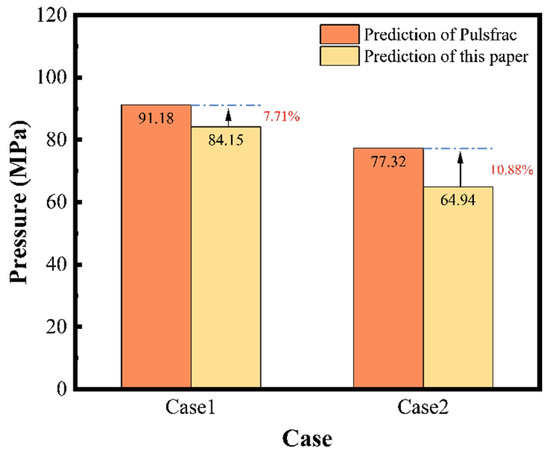
Figure 21.
Comparison of the two predictive models.
5. Conclusions
Drawing upon underwater explosion theory, numerical simulation, and nonlinear regression fitting, this paper conducts predictive modeling of perforating shock load and derives the following conclusions:
- The pressure variation process of shock waves propagating in a confined wellbore based on the theory of underwater explosion was analyzed. Meanwhile, the energy composition was examined during perforation, particularly focusing on the jetting process of shaped charges. The analysis indicated that residual perforation energy is a critical factor affecting the safety of the perforating tubing string system.
- The pulsating pressure of the perforating fluid significantly impacted the dynamic response of the tubing. To address this, a numerical model of the perforating explosion process was established. By analyzing the contour plots, the propagation of the shock wave within the perforating fluid could be clearly understood. Additionally, the feasibility of this numerical model was validated through comparison with actual field-measured data.
- A finite element simulation model was developed to capture the dynamic response of the perforating tubing string system. Quantitative numerical simulation analysis conclusively demonstrates that the peak perforating pressure is critically influenced by operational parameters: total charge mass exerts the strongest effect, proportionally increasing pressure from 162 MPa to 388 MPa (140% rise); explosion space shows an inverse relationship, where pressure plummets 35% (from 376 MPa to 243 MPa) as space expands from 0 to 5 m3; formation pressure (directly linked to initial wellbore pressure) drives a linear increase from 315 MPa to 372 MPa across 0–100 MPa; fluid density (1–3 g/cm3) causes a significant 78% surge (335 MPa to 598 MPa). A dimensionless analysis and an orthogonal experiment design with five factors and four levels were conducted, leading to 16 numerical simulation results for the loads under varying conditions.
- The numerical simulation results were fitted using the curve_fit function from the Scipy library, resulting in a predictive model for peak perforating shock load that aligns with the requirements of field operations. To validate the model, it is applied to the operation parameters of two wells, comparing the results with those from the Pulsfrac. The prediction errors for loads of the two were around 10%, demonstrating that the model developed in this study is reliable and can meet the engineering needs of actual perforation operations.
Author Contributions
Writing—review and editing, K.Z.; Conceptualization, Q.D. and J.J.; Formal analysis, H.Z. and J.N.; Methodology, Q.D., J.J. and H.H. All authors have read and agreed to the published version of the manuscript.
Funding
This study was supported by the Open Foundation of Cooperative Innovation Center of Unconventional Oil and Gas, Yangtze University (Ministry of Education and Hubei Province), No. UOG2024-06; the Open Foundation Project of the Key Laboratory of Polar Geology and Marine Mineral Resources (China University of Geosciences, Beijing), Ministry of Education (Number: PGMR-2024-106); the Key Program of the Hubei Provincial Department of Education, No. D20221303; and the Natural Science Foundation of Hubei Province, No. 2022CFB700.
Institutional Review Board Statement
This study did not require ethical approval.
Informed Consent Statement
This study did not involve humans.
Data Availability Statement
The original contributions presented in this study are included in the article. Further inquiries can be directed to the corresponding author.
Conflicts of Interest
Author Kui Zhang was employed by the CNPC Engineering Technology R&D Company Limited. Author Honglei Zhang and Jiejing Nie were employed by the Beijing Petroleum Machinery Co., Ltd. Author Jiadong Jiang was employed by the SJ Petroleum Machinery Co. The remaining authors declare that the research was conducted in the absence of any commercial or financial relationships that could be construed as a potential conflict of interest.
References
- Brinsden, M.S.; Boock, A.; Baumann, C.E. Perforating Gunshock Loads: Simulation Capabilities and Applications. In Proceedings of the International Petroleum Technology Conference, Kuala Lumpur, Malaysia, 10–12 December 2014. [Google Scholar] [CrossRef]
- Baumann, C.; Brinsden, M. Perforating Gunshock Loads: Simulation and Optimization in 2014. In Proceedings of the IADC/SPE Asia Pacific Drilling Technology Conference, Bangkok, Thailand, 25–27 August 2014. [Google Scholar] [CrossRef]
- Schatz, J.F.; Schatz, J.F.; Folse, K.C.; Fripp, M.; Dupont, R. High-Speed Pressure and Accelerometer Measurements Characterize Dynamic Behavior During Perforating Events in Deepwater Gulf of Mexico. In Proceedings of the SPE Annual Technical Conference and Exhibition, Houston, TX, USA, 26–29 September 2004. [Google Scholar] [CrossRef]
- Baumann, C.; Gultom, D.; Salsman, A.; Smart, M.; Primasari, I.; Rahman, R.; Warsito, S. Perforating on Wireline: Maximizing Productivity and Minimizing Gunshock. In Proceedings of the SPE European Formation Damage Conference and Exhibition, Budapest, Hungary, 3–5 June 2015. [Google Scholar] [CrossRef]
- Gilliat, J.; Bale, D.; Satti, R.; Li, C.; Howard, J. The Importance of Pre-Job Shock Modeling as a Risk Mitigation Tool in TCP Operations. In Proceedings of the SPE Deepwater Drilling and Completions Conference, Galveston, TX, USA, 10–11 September 2014. [Google Scholar] [CrossRef]
- Deng, Q.; Jiang, J.; Yang, D.; Han, H.; Qi, G. Dynamic analysis and optimization of perforated tubing strings in deep-water wells under diverse operating conditions. Ocean Eng. 2025, 322, 120535. [Google Scholar] [CrossRef]
- Canal, A.C.; Miletto, P.; Schoener-Scott, M.F.; Medeiros, J.; Barlow, D. Predicting Pressure Behavior and Dynamic Shock Loads on Completion Hardware During Perforating. In Proceedings of the Offshore Technology Conference, Houston, TX, USA, 3–6 May 2010. [Google Scholar] [CrossRef]
- Baumann, C.; Williams, H.; Korf, T.; Pourciau, R. Perforating High-Pressure Deepwater Wells in the Gulf of Mexico. In Proceedings of the SPE Annual Technical Conference and Exhibition, Denver, CO, USA, 30 October–2 November 2011. SPE-146809-MS. [Google Scholar] [CrossRef]
- Baumann, C.E.; Guerra, J.P.; William, A.; Williams, H.A. Reduction of perforating gunshock loads. SPE Drill. Complet. 2012, 27, 65–74. [Google Scholar] [CrossRef]
- Baumann, C.; Benavidez, M.; Martin, A.; Salsman, A.; Williams, H. Perforating on Wireline-Weak-Point Load Prediction. In Proceedings of the SPE, EAGE European Unconventional Resources Conference and Exhibition, Vienna, Austria, 20–22 March 2012. SPE-152431-MS. [Google Scholar] [CrossRef]
- Baumann, C.; Lazaro, A.; Valdivia, P.; Williams, H.; Stecchini, P. Perforating Gunshock Loads-Prediction and Mitigation. In Proceedings of the SPE/IADC Drilling Conference and Exhibition, Amsterdam, The Netherlands, 5–7 March 2013. SPE-163549-MS. [Google Scholar] [CrossRef]
- Sanders, W.; Baumann, C.E.; Williams, H.A.; de Moraes, F.D.; Shipley, J.; Bethke, M.E.; Ogier, S. Efficient Perforation of High-Pressure Deepwater Wells. In Proceedings of the Offshore Technology Conference, Houston, TX, USA, 2–5 May 2011. OTC-21758-MS. [Google Scholar] [CrossRef]
- Brinsden, M.; Gavric, Z.; Le, C.; Baumann, C.; Smart, M.; Stulb, C. Perforating the Largest High-Pressure Wells in the Gulf of Mexico. In Proceedings of the Offshore Technology Conference Asia, Kuala Lumpur, Malaysia, 22–25 March 2016. D011S006R001. [Google Scholar] [CrossRef]
- Bale, D.; Ji, M.; Satti, R.; Gilliat, J. Advances in Numerical Modeling of Downhole Dynamics for Perforated Well Completions. In Proceedings of the SPE Annual Caspian Technical Conference and Exhibition, Astana, Kazakhstan, 1–3 November 2014. [Google Scholar] [CrossRef]
- Magri, J.L.; Scudino-Borges, R.P.; Jeronimo-Junior, E. Determination of load effects on a sealbore packer with floating seal assemblies during a dynamic underbalanced perforation. In Proceedings of the SPE Latin America and Caribbean Petroleum Engineering Conference, Buenos Aires, Argentina, 17–19 May 2017. D031S019R002. [Google Scholar] [CrossRef]
- Liu, J.; Jian, Y.; Chen, Y.; Tang, K.; Ren, G.; Chen, J. Shock vibration response characteristic of perforating tubing string in ultra-deep wells. Geoenergy Sci. Eng. 2023, 228, 212008. [Google Scholar] [CrossRef]
- Cole, R.H.; Weller, R. Underwater Explosions; Princeton University Press: Princeton, NJ, USA, 1948. [Google Scholar]
- Guoxiang, S.; Xiaofeng, W.; Fugen, S. Explosives for the Perforators of Oil and Gas Wells and Their Safety. Explos. Mater. 2002, 31, 4–9. [Google Scholar]
- Haggerty, D.; McGregor, J.; Barker, J.; Manning, D.; DeHart, R. Penetration Performance of a Shaped Charge Perforator in Sandstone and Limestone Targets at Extreme Pore Pressures and Constant Effective Stress. In Proceedings of the International Petroleum Technology Conference, Bangkok, Thailand, 14–16 November 2016. [Google Scholar] [CrossRef]
- Ding, L.; Chen, W.; Han, C.; Xue, Y.; Lei, Q. Study on Explosion Energy Conversion of a Perforating Shaped Charge during Perforation Detonation. SPE J. 2024, 29, 2938–2952. [Google Scholar] [CrossRef]
- Xin, G.; Qing, Z. Progress in numerical simulation of dam failure under blast loading. J. Hohai Univ. 2017, 45, 45–55. [Google Scholar]
- Miao, G.; Hu, Y.; AI, J.; Ma, Q.; Sun, Z.; Ma, H.; Shen, Z. Numerical simulation of explosive welding of metal tube and rod based on different algorithms. Trans. China Weld. Inst. 2022, 43, 64–71+116–117. [Google Scholar]
- Chen, F.; Chen, H.; Tang, K.; Ren, G. Influence of perforating impact load on the operating string and the countermeasures. Nat. Gas Ind. 2010, 30, 61–65. [Google Scholar]
- Deng, Q.; Zhang, H.; Li, J.; Hou, X.; Wang, H. Analysis of Impact Load on Tubing and Shock Absorption during Perforating. Open Phys. 2019, 17, 214–221. [Google Scholar] [CrossRef]


Disclaimer/Publisher’s Note: The statements, opinions and data contained in all publications are solely those of the individual author(s) and contributor(s) and not of MDPI and/or the editor(s). MDPI and/or the editor(s) disclaim responsibility for any injury to people or property resulting from any ideas, methods, instructions or products referred to in the content. |
© 2025 by the authors. Licensee MDPI, Basel, Switzerland. This article is an open access article distributed under the terms and conditions of the Creative Commons Attribution (CC BY) license (https://creativecommons.org/licenses/by/4.0/).