Abstract
The bore field in ground source heat pump (GSHP) systems usually encounters thermal accumulation in long-term operation, but there is no quantitative index evaluating this process and its magnitude. A heat accumulation evaluation metric has been proposed, based on the linear trend Slope (°C/a) of the curve of soil temperature variation. Using this metric, the influence of various factors on soil temperature has been quantitatively analyzed. The results indicate that, under constant heating durations, each 10-day extension of cooling periods leads to an increase of 0.038 °C/a in soil temperature. Extending the recovery period within an annual cycle facilitates soil self-recovery and mitigates subsurface thermal accumulation. Increasing the spacing between boreholes effectively reduces thermal interference, whereas a greater number of boreholes exacerbates thermal accumulation. Deepening vertical boreholes from 100 m to 200 m reduces the average annual soil temperature increase by 0.1076 °C. Appropriately increasing backfill thermal conductivity enhances heat exchange efficiency and suppresses thermal accumulation. Higher water flow rates result in logarithmic increases in the evaluation metric, thereby intensifying soil thermal accumulation. Intermittent operation extends recovery periods, thereby alleviating soil thermal imbalance. Under balanced cooling and heating loads, increasing the system lifespan from 10 a to 30 a reduces the evaluation metric by 47.2%.
1. Introduction
China has set strategic goals to achieve peak carbon emissions by 2030 and carbon neutrality by 2060. The building sector constitutes a substantial share of the nation’s total energy consumption [1,2]. As an emerging clean and renewable energy source, shallow geothermal energy is characterized by broad availability and long-term sustainability [3]. Ground source heat pump (GSHP) systems harness geothermal energy to deliver heating and cooling for buildings [4]. With the widespread application of shallow GSHP systems, their operational challenges have become increasingly apparent. Under different operating conditions and underground thermal status [5], GSHP systems are subject to varying heating and cooling loads. Over time, sustained heat injection or extraction may cause significant thermal/cold accumulation in subsurface geological formations, potentially leading to gradual efficiency degradation and, in severe cases, system failure [6,7,8,9]. As critical components for thermal energy exchange, the performance optimization of heat exchangers plays a vital role in enhancing the efficiency of ground source heat pump (GSHP) systems. Rostami et al. [10] demonstrated that optimizing the geometric configuration of double-pipe heat exchangers can significantly improve thermal performance. These findings provide important theoretical support for the present study’s quantification of subsurface thermal imbalance. Muneeshwaran M et al. [11] reported that uneven flow distribution in plate heat exchangers during long-term operation may lead to localized heat accumulation, which can compromise system stability.
Currently, the most common vertical ground heat exchangers include single U-tube, double U-tube, and coaxial borehole heat exchangers. Compared to U-type borehole heat exchangers (BHEs), CBHEs (coaxial borehole heat exchangers) offer superior heat transfer performance, reduced land use requirements, and enhanced adaptability to site constraints and are therefore selected as the focus of this study. As illustrated in Figure 1, the operational process of shallow GSHP systems initiates with heat exchange between ground heat exchangers and soil. CBHEs transfer thermal energy to the surrounding soil through circulating water. During winter, low-temperature circulating water absorbs thermal energy stored in the soil and is then driven by circulation pumps to the evaporator of the heat pump unit, where a phase change in the refrigerant upgrades the low-grade thermal energy to high-grade thermal energy. Subsequently, it is pressurized and heated by the compressor and then releases thermal energy to the building heating system via the condenser. In summer, the heat pump unit operates in reverse cycle. Circulating water absorbs excess indoor heat via the condenser, exchanges heat with the ground through the CBHEs, and ultimately discharges the thermal energy into the surrounding soil. The essence of the ground heat exchanger lies in two aspects. One is the utilization of existing thermal energy buried underground. Another is seasonal heat storage. The cooling energy extracted in summer from underground can be seen as the energy stored in the previous winter. The heating energy extracted in winter from underground can be seen as the heat energy stored in the previous summer.
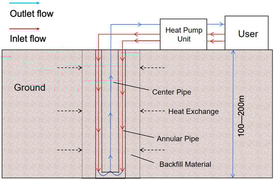
Figure 1.
Schematic of a shallow coaxial borehole heat exchanger.
There has been extensive research on heat transfer processes in CBHEs globally, which can be broadly categorized into two types: analytical heat transfer models and numerical heat transfer models.
In the development of analytical heat transfer models, Kelvin [12] first proposed the infinite line source model. Based on this, Ingersoll et al. [13] extended the model to describe heat transfer in coaxial borehole heat exchangers (CBHEs) as a one-dimensional transient heat conduction process originating from an infinite linear heat source. However, this model neglects the influence of axial heat transfer in the borehole. Later, Carslaw and Jaeger [14] developed the infinite cylindrical source theory based on line source theory. Additionally, the “solid” cylindrical source model proposed by Yi Man et al. [15] shows improved agreement with field measurements compared to other analytical models, making it suitable for long-term performance evaluations of borehole heat exchangers (BHEs). Yongqiang Luo [16] et al. discretized the borehole heat source in terms of time and space, enabling the analytical solution to be applied to heat transfer processes in subsurface regions.
In the context of numerical heat transfer modeling, well-established numerical methods include the finite volume method [17] and the finite difference method [18]. These solution methods have been widely applied in commercial and open-source software, such as FLUENT 2025R1, COMSOL 6.3, FELLOW 1.4.0, TRNSYS 18, etc. These software packages efficiently incorporate geological conditions, such as geothermal gradients and stratigraphic heterogeneity, enabling accurate prediction of subsurface temperature fields and circulating fluid temperatures throughout BHEs. Cai et al. [19] developed a numerical model based on geothermal gradients and stratified thermophysical properties of geological formations to investigate the heat exchange performance of DBHEs. Cui P [20] developed a two-dimensional numerical simulation model for ground heat exchangers based on TRNSYS software. On this basis, he systematically investigated the dynamic operational characteristics of GSHP systems under intermittent operation conditions and dual-mode cooling/heating operation schemes.
Numerous factors beyond cooling and heating load imbalances influence soil temperature in ground source heat pump (GSHP) systems. Key parameters such as the duration of thermal recovery within annual cycles, system operating hours, and operational strategies significantly affect the subsurface temperature field. Substantial research addresses thermal imbalance mitigation, with hybrid heat pump systems emerging as a proven effective solution [21]. Penrod [22] established a hybrid GSHP system by integrating solar collectors with conventional GSHP infrastructure and subsequently analyzed the operational principles of this coupled configuration. In southern China, where building cooling demand significantly exceeds heating demand, Rui Fan et al. [23] proposed an ice-storage hybrid GSHP system. Their results demonstrated that this approach effectively mitigates thermal accumulation and significantly reduces soil thermal imbalance. Furthermore, implementing intermittent operational strategies during GSHP system operation promotes soil thermal recovery, mitigates subsurface thermal accumulation, and helps ensure efficient, stable, and long-term system performance [24]. Yang et al. [25] investigated intermittent operation strategies for a hybrid GSHP system integrated with dual cooling towers. Their simulation results indicated that intermittent operation can substantially reduce soil heat accumulation, energy consumption, and operating costs.
Based on the above literature review, the research gaps are identified as follows:
- 1.
- The current studies mainly reflect the degree of accumulation through soil temperature rise, lacking standardized quantitative evaluation metrics.
- 2.
- The current studies fail to reflect the trend of soil temperature changes during long-term operation of the system.
- 3.
- There is a shortage of comprehensive analyses on various design and operating factors on the thermal accumulation of a shallow borehole array.
In order to resolve the research gaps, the present study established an analytical heat transfer model for shallow CBHE arrays. The core novelty is proposing a new index quantifying thermal accumulation of bore fields in a long-term operation. The main contribution is the analysis of factors that affect underground temperature, including building cooling/heating loads, recovery period duration, borehole spacing/density, backfill thermal conductivity, vertical borehole depth, and operational parameters. The conclusion, as well as methods, contribute to the field of ground source heat pumps.
2. Methods
2.1. Basic Assumptions
The heat transfer between the circulating fluid inside the underground pipes and the surrounding rock and soil is a complex process. It encompasses convective heat transfer between the fluid and pipe interior, conduction through the pipe walls, conduction from the pipe’s outer surface to the backfill material, conduction between the backfill and borehole walls, and, finally, conduction from the borehole walls into the adjacent rock and soil. To facilitate the study and analysis of the heat transfer process in CBHEs, the following assumptions are made:
- (1)
- The initial soil temperature is assumed to be based on the geothermal gradient;
- (2)
- The inlet temperature or heat flux density of the circulating fluid in the pipe is assumed to be constant;
- (3)
- The influences of evaporation, diffusion, and condensation of the circulating fluid within the pipe, along with groundwater seepage, are neglected in the thermal conduction analysis of the rock and soil;
- (4)
- The rock and soil are treated as a homogeneous medium characterized by constant and uniform thermal properties, such as thermal conductivity, specific heat capacity, and thermal diffusivity.
2.2. Mathematical Model
This study divides the heat transfer process of a shallow coaxial borehole heat exchanger (CBHE) into two segments: inside and outside the borehole. Separate energy balance equations are formulated for both the surrounding rock mass and the circulating fluid within the pipe. Based on these, an analytical solution model for heat transfer in shallow CBHE systems is developed. Utilizing this model, the temporal variations in the subsurface temperature field under prolonged system operation are simulated and examined.
For the heat transfer process outside the borehole, the finite line source model demonstrates high fidelity to field monitoring data during long-term operation simulations [26]. The excess temperature caused by the descending segment at time τ and point (r, 0, z) can be obtained as follows:
where θ is the excess temperature at the calculation point, °C; H is the length of the vertical borehole, m; q is the heat extraction per unit length of the borehole, W/m; r is the radial distance at the calculation point, m; z is the axial distance at the calculation point, m; k is the thermal conductivity of the rock and soil medium, W/(K·m); a is the thermal diffusivity of the rock and soil, m2/s; and τ is the operation time, s.
The essence of Equation (1) is to establish a direct connection between the intensity of a line heat source and the excess temperature at a location of (r, z) at any time node. The integration in Equation (1) means a calculation of the true heat source underground and a virtual heat source at a mirrored place. Those two heat sources together formulate a constant-temperature boundary at the ground surface.
The heat transfer process within the borehole is mainly computed using the finite difference method combined with the energy balance equation [27]. This calculation accounts for three key components: convective heat transfer among fluids, conductive heat transfer within fluids, and conductive heat transfer between fluids and the adjacent soil. The heat transfer occurring inside the pipe is treated as a one-dimensional process. The energy equations for the fluid in the descending pipe segment and the ascending pipe segment can be expressed as follows:
where Tf1 and Tf2 are the fluid temperatures in the descending and ascending pipe segments, respectively, °C; Tb is the temperature of the borehole wall, °C; m is the mass flow rate of the circulating fluid, kg/s; cf is the specific heat capacity of the circulating fluid, J/(kg·°C); R12 and Rb are the thermal resistances between the central pipe and the annular pipe and between the annular pipe and the pipe wall, respectively, m2 K/W; and Ci is the sum of the thermal capacitance of materials per unit length inside the borehole, J/(kg·K).
Equations (2) and (3) are ordinary differential equations describing the downward flow and upward flow in the coaxial borehole. The heat transfer between the annulus and center pipe is described by the thermal resistance of R12. Because the fluid enters the annulus pipe, the thermal interaction is determined by the thermal resistance of Rb.
2.3. Calculation Process
This section presents simulations conducted by developing computational codes that model the heat transfer phenomena occurring both within and around the borehole. Regarding the heat transfer within the borehole, the fluid temperature at time step k + 1 can be calculated using the inlet temperature at time k, along with the wall temperatures of each pipe segment and the fluid temperature in the current step. For the heat transfer process outside the borehole, based on the wall temperatures of each pipe segment and the heat flux density at time k, the wall temperature at time k + 1 can be determined. After coupling the two processes, the above process is repeated until the simulation duration is reached. The calculation flowchart is shown in Figure 2.
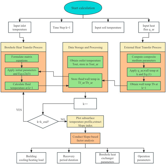
Figure 2.
Schematic of the calculation process.
In Figure 2, the core simulation process is the “Borehole Heat Transfer Process” and “External Heat Transfer Process”. These two steps are in charge of simulating the fluid temperature inside the borehole and the borehole wall temperature at each time step iteration. The data exchange between these two parts is realized by the “Data Storage and Processing” step by passing their heat flux data or borehole wall. If the simulation time exceeds the preset value, the simulation will stop and proceed to the next step, where the “Slope index” is extracted, which defines the thermal accumulation level. After that, various factors are analyzed, in terms of building cooling/heating load, etc.
3. Results
3.1. Model Validation
This section validates the proposed mathematical model through a comparative analysis between simulation outcomes and experimental data reported in previous studies. The experimental data are sourced from Beier RA et al. [26]. Table 1 specifies the fundamental parameters, including a geothermal gradient of 0.03 °C/m and a simulation duration of 75 h. The sizing and thermal parameters in Table 1 are common values for CBHE. It should be specially noted that the model parameters of steps Δz and Δτ can be adjusted according to demand. A smaller space step will produce a finer simulation result, but it will also require a longer computation time. A comparison between the simulation outputs and experimental measurements is presented in Figure 3. The results indicate that the maximum error between the simulated outlet water temperature and the experimental outlet water temperature is 3.61%. The numerically simulated outlet temperature of the ground-coupled heat exchanger shows strong agreement with the observed monitoring data, confirming the model’s high reliability. It is observed that the simulation results are slightly higher than the experimental data. This is probably caused by inaccurate parameters in Table 1 or the experimental error itself.

Table 1.
Basic parameters.
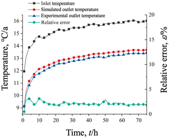
Figure 3.
Comparison of simulated outlet temperature with experimental data.
3.2. The Heat Accumulation Evaluation Metric
During long-term operation of GSHP systems, building cooling/heating load imbalances induce progressive directional changes in soil temperatures. This manifests as sustained thermal accumulation phenomena underground, characterized by either monotonic warming or cooling trends. Based on the heat transfer analytical solution model established, a ten-year simulation of the system is conducted to study the temperature variation over time at a depth of 85 m from the center pipe wall. The results showed that the soil temperature variation over time was composed of a linear trend line and a periodic curve. The curve could be split, as shown in Figure 4a. We adopt the linear trend Slope as the evaluation metric. To verify its accuracy, secondary decomposition of the periodic curve is performed, as shown in Figure 4b. After secondary decomposition, the Slope of the linear trend approaches 0, indicating that the Slope metric meets the accuracy requirements. Considering the linear trend is negligible in the second-round decomposition, there is no need for another decomposition. The temperature curve is obtained under a constant cooling or heating load profile, but the linear trend extraction method will not be influenced if a real-world load profile is imposed. This method works equally well for both cooling and heating situations.
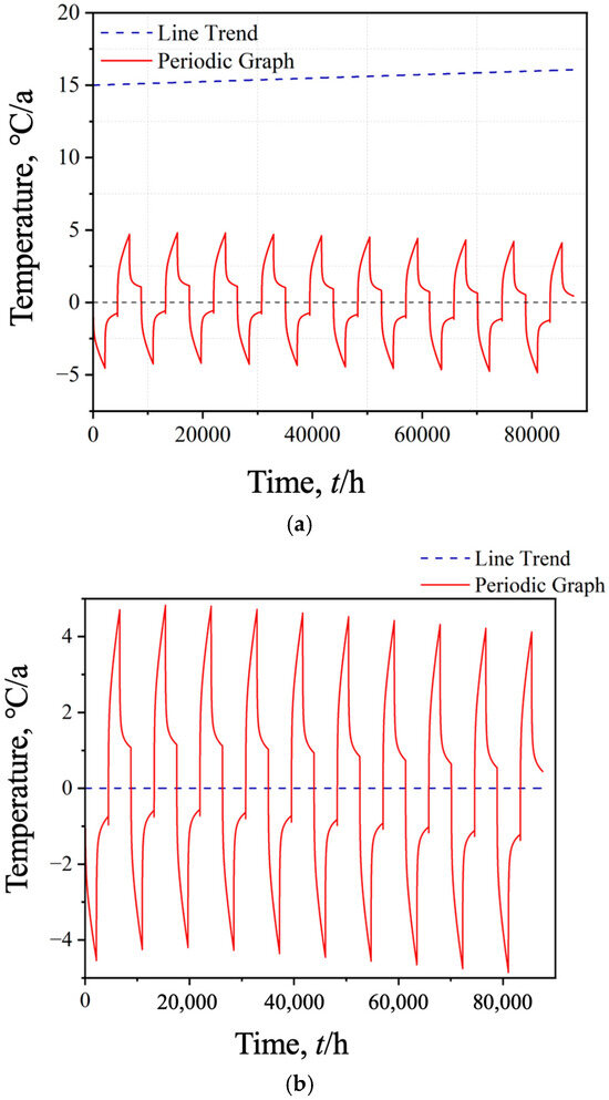
Figure 4.
(a) Primary decomposition results of subsurface temperature profiles. (b) Secondary decomposition results of subsurface temperature profiles.
The sign and magnitude of the Slope metric (°C/a) determine both the polarity and severity of subsurface thermal accumulation. A positive Slope signifies heat accumulation, where soil temperature increases progressively over time, with higher values indicating greater severity. A negative Slope denotes cold accumulation, characterized by a progressive temperature decrease, where more negative values reflect increased severity. While Slope (°C/h) serves as a subsurface thermal accumulation metric, its small value makes it difficult to intuitively determine the extent of thermal accumulation. Therefore, this study adopts Slope (°C/a) as the standardized indicator for quantifying thermal accumulation.
4. Discussion
Building upon the previously established analytical heat transfer model and the heat accumulation evaluation metric Slope (°C/a), this section conducts a parametric sensitivity analysis to quantify the influence of building cooling/heating loads, recovery period duration, borehole spacing/density, vertical borehole depth, backfill thermal conductivity, and operational parameters.
4.1. Building Cooling/Heating Loads and Recovery Period Duration
The changes in the building’s cooling/heating loads and recovery period duration are simulated by changing the number of days the system operates during a one-year cycle. The GSHP system is simulated for ten years, and the results are shown in Figure 5 and Figure 6.
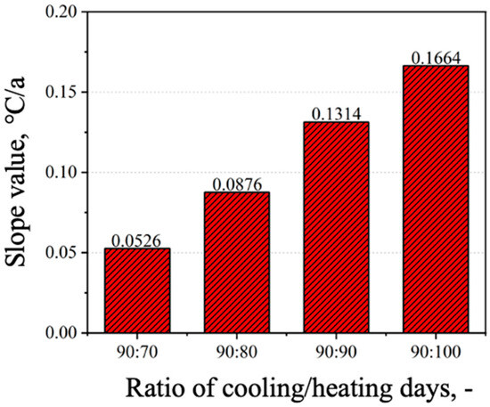
Figure 5.
The Slope value under different building loads.
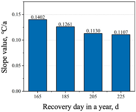
Figure 6.
The Slope value under different recovery period durations.
Under constant heating season duration, as the cooling time increases, the degree of soil heat accumulation gradually deepens. For every ten days of additional operating time during the cooling season, the Slope (°C/a) metric increases by 0.038, meaning the soil temperature rises by 0.038 °C annually. When the number of heating and cooling days decreases proportionally, the recovery period lengthens within the operating cycle, and the Slope (°C/a) metric gradually decreases, alleviating soil heat accumulation.
In a study by Gao et al. [28], three scenarios of heating-to-cooling ratios (6:1, 2.4:1, and 1:1) were conducted for a comparison of the thermal performance of vertical and horizontal ground heat exchangers. And Cheng et al. [29] designed similar heating-to-cooling ratios (2:1, 1:1, and 1:2) for the investigation of mixed shallow and deep boreholes. Although these studies involved multi-year analyses, no index was used for the quantification of the heat accumulation within boreholes.
4.2. Borehole Spacing and Density
Increasing the spacing between boreholes is the simplest and most effective way to alleviate soil heat accumulation and reduce thermal interference between buried pipes [30]. However, increasing the number of boreholes not only raises the initial investment cost of the system but also exacerbates thermal interference effects between boreholes. By varying the spacing and number of boreholes, the system is simulated over a ten-year period, with the results shown in Figure 7 and Figure 8. Increasing the spacing between boreholes reduces thermal interference between buried pipes, while increasing the number of boreholes exacerbates thermal interference between pipes and deepens soil heat accumulation.
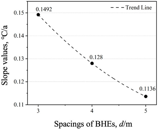
Figure 7.
The Slope value under different BHE spacings.
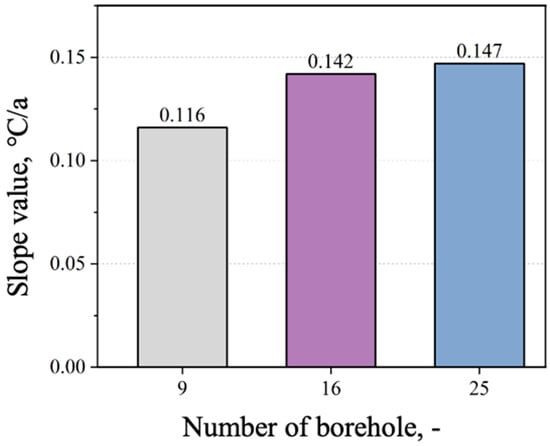
Figure 8.
The Slope value under different BHE densities.
4.3. Vertical Borehole Depth
Figure 9 illustrates the impact of vertical borehole depth on subsurface thermal accumulation. As borehole depth increases, the thermal load per unit depth decreases, resulting in an exponential reduction in the Slope (°C/a) metric. This demonstrates that greater vertical borehole depths effectively mitigate soil thermal accumulation. When depth extends from 100 m to 200 m, Slope decreases from 0.1225 to 0.0149 °C/a, corresponding to a 0.1076 °C reduction in the average annual soil temperature rise.
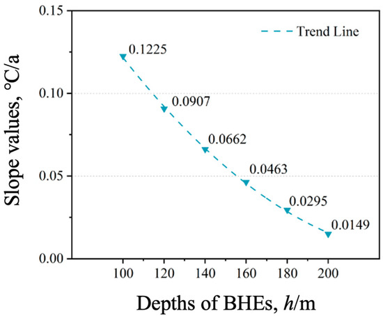
Figure 9.
The Slope value under different vertical borehole depths.
4.4. Backfill Thermal Conductivity
To examine the influence of backfill thermal conductivity on heat accumulation in the surrounding soil, the parameter is systematically varied at values of 1.5, 2.0, 2.5, 3.0, and 3.5 W/(m·K). The results are shown in Figure 10. While increased conductivity reduces the Slope(°C/a) metric, indicating mitigated heat accumulation, the improvement magnitude remains limited. The effect is attributed to improved heat conduction between the pipe and soil at higher backfill conductivities. Nonetheless, if the conductivity of the backfill greatly exceeds that of the soil, the benefit may diminish due to mismatched thermal properties. Heat becomes concentrated near the pipes rather than dissipating radially, thus diminishing the Slope reduction effect.
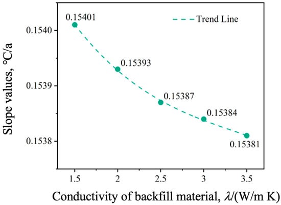
Figure 10.
The Slope value under different backfill thermal conductivities.
4.5. Circulating Water Flow Rate
The flow rate of circulating water is adjusted incrementally to 0.5, 1.0, 1.5, 2.0, 2.5, and 3.0 m3/h, and the corresponding results are illustrated in Figure 11. Increasing the flow rate enhances the convection coefficient between the fluid and the pipe walls, leading to an increase in the heat transfer rate per unit time. Consequently, more thermal energy is conducted to the surrounding soil per unit time, deepening soil thermal accumulation. However, equal flow increments produce diminishing temperature rises, and soil warming progressively attenuates at higher flow rates.
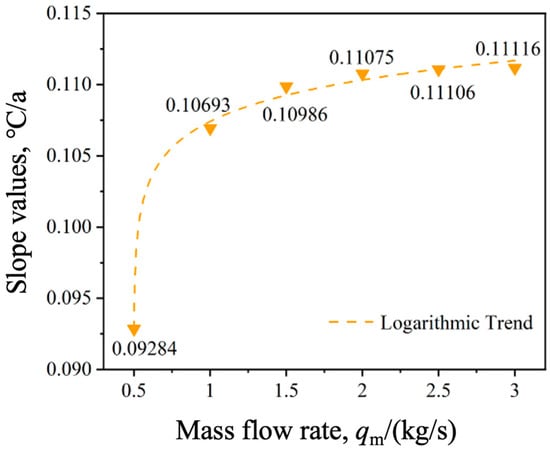
Figure 11.
The Slope Value under different water flow rates.
There are also many studies that discussed the impact of flow rate on system performance, even including a discussion of the heat accumulation level in the long run. For example, Shao et al. [31] studied the annual extreme temperature change at the outlet under different flow rate situations. However, the analysis in their study can only be described by temperature changes, as it did not use an index to quantify the heat accumulation.
4.6. Operating Mode
Four operational modes are simulated: continuous operation, 2 h operation/2 h pause, 6 h operation/2 h pause, and 6 h operation/6 h pause. The simulated operational results are shown in Figure 12. As shown in the results, compared to continuous operation, intermittent operation results in a longer soil recovery period, which helps alleviate soil thermal accumulation. The longer the intermittent duration, the more beneficial it is for natural soil recovery. Compared to 6 h/6 h, 2 h/2 h reduces soil temperature by 0.036 °C annually. Similarly, a previous study by Zhao et al. [32] described the latest progress in controlling the thermal accumulation of ground source heat pump systems, but it did not use a quantification index, unlike the current study.
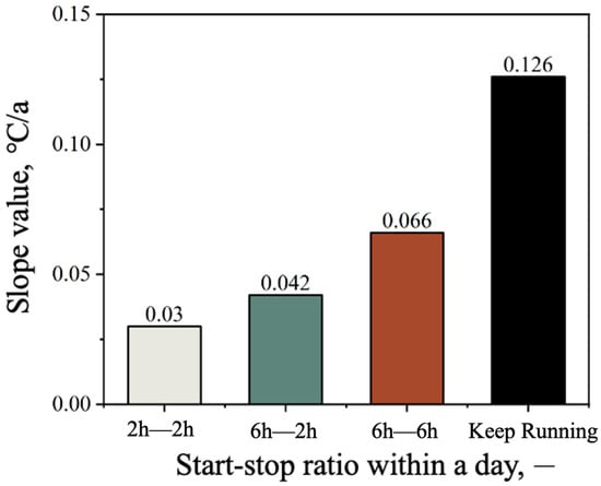
Figure 12.
The Slope value under different operating modes.
4.7. Operating Years
To study the impact of system operating years on soil heat accumulation, we simulate the system’s operation for 10, 20, and 30 years. The results are shown in Figure 13. Analysis of the corresponding Slope (°C/a) metrics reveals that extended operation significantly mitigates thermal accumulation under balanced annual cooling/heating loads. Prolonged operation facilitates thermal diffusion, promoting homogeneous heat distribution across broader geological volumes and reducing localized accumulation rates.
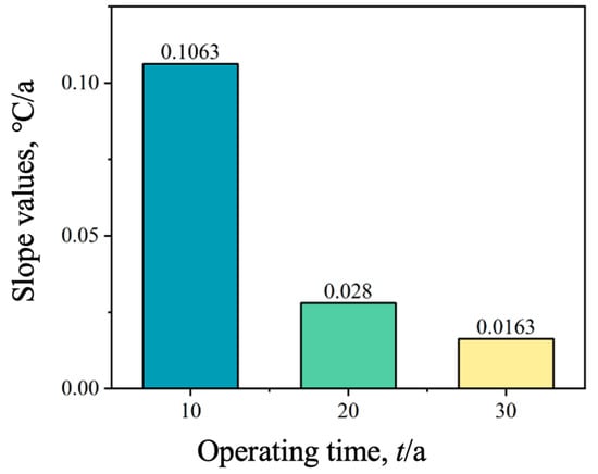
Figure 13.
The Slope value under different operating years.
5. Conclusions
5.1. Conclusion
During long-term operation of shallow ground source heat pump (GSHP) systems, soil thermal imbalance can significantly impair heat exchange efficiency and may eventually lead to system failure. Although this phenomenon has been widely researched in previous studies, there is still no quantification index that can be used for this evaluation directly. Moreover, there is a shortage of comprehensive analyses that quantify the direct links between various parameters and the level of thermal accumulation. In this study, an analytical heat transfer model was developed for shallow coaxial borehole heat exchangers (CBHEs), and a heat accumulation evaluation metric, referred to as the Slope (°C/a), was introduced to quantify subsurface thermal imbalance.
- 1.
- The simulation results of the shallow CBHE heat transfer model show good agreement with the experimental measurements. Once the system reaches steady-state operation, the maximum error is 3.61%, remaining within a 5% margin.
- 2.
- The linear trend Slope extracted from subsurface temperature profiles serves as the heat accumulation evaluation metric. Its sign and magnitude precisely quantify both the directionality (heat or cold accumulation) and severity of subsurface thermal imbalance. Based on this metric, a quantitative analysis of the relevant influencing factors was conducted.
- 3.
- Extending recovery periods, increasing borehole spacing, deepening vertical boreholes, enhancing backfill thermal conductivity, reducing circulating flow rates, and implementing intermittent operation all mitigate subsurface thermal accumulation. Among these factors, increasing borehole depth had the most pronounced effect: when the depth was increased from 100 m to 200 m, a reduction of 1.076 °C in the average annual temperature rise was observed.
5.2. Outlook
- 1.
- The model does not consider the impact of groundwater seepage. In future research, the existing model can be coupled with groundwater seepage to improve simulation accuracy. Considering that convective heat transfer may influence the results in a noticeable way, future studies should investigate the effect of groundwater flow rate and temperature on the thermal accumulation of bore fields.
- 2.
- This study assumes constant cooling/heating loads during long-term system operation, whereas actual engineering applications exhibit significant dynamic load fluctuations. Since the main purpose of this study was to reveal the relationship between various design and operation parameters and the thermal accumulation index, and considering that the thermal load profile in the real world is a more complex curve, future research should address this limitation through advanced methodologies.
- 3.
- Shallow GSHP systems can be combined with auxiliary equipment, such as solar collectors [33,34], to alleviate the phenomenon of soil heat accumulation.
Author Contributions
Conceptualization, R.L. and Y.L. (Yongqiang Luo); methodology, W.H.; software, C.Z.; formal analysis, Y.H. and Y.L. (Yongqiang Luo) and Y.L. (Yuce Liu); investigation, T.H.; resources, M.W.; project administration, C.Z.; funding acquisition, Y.L. (Yongqiang Luo). All authors have read and agreed to the published version of the manuscript.
Funding
This research was funded by China Yangtze Power Co., Ltd., under grant number Z342302007.
Data Availability Statement
The raw data supporting the conclusions of this article will be made available by the authors on request.
Conflicts of Interest
Rujie Liu, Wei He and Tao Han are employees of the China Yangtze Power Co., Ltd. Chaohui Zhou, Yue Hu, Yuce Liu and Meng Wang are employees of the CTG Wuhan Science and Technology Innovation Park, China Three Gorges Corporation. All authors are contributing to this work and declaim that there is no conflict of interests.
References
- Amasyali, K.; El-Gohary, N.M. A Review of Data-Driven Building Energy Consumption Prediction Studies. Renew. Sustain. Energy Rev. 2018, 81, 1192–1205. [Google Scholar] [CrossRef]
- Liu, J.; Wang, F.; Gao, Y.; Zhang, Y.; Cai, W.; Wang, M.; Wang, Z. Influencing Factors Analysis and Operation Optimization for the Long-Term Performance of Medium-Deep Borehole Heat Exchanger Coupled Ground Source Heat Pump System. Energy Build. 2020, 226, 110385. [Google Scholar] [CrossRef]
- Lund, J.W.; Huttrer, G.W.; Toth, A.N. Characteristics and Trends in Geothermal Development and Use, 1995 to 2020. Geothermics 2022, 105, 102522. [Google Scholar] [CrossRef]
- Yuan, Y.; Cao, X.; Sun, L.; Lei, B.; Yu, N. Ground Source Heat Pump System: A Review of Simulation in China. Renew. Sustain. Energy Rev. 2012, 16, 6814–6822. [Google Scholar] [CrossRef]
- Urresta, E.; Moya, M.; Campana, C.; Cruz, C. Ground Thermal Conductivity Estimation Using the Thermal Response Test with a Horizontal Ground Heat Exchanger. Geothermics 2021, 96, 102213. [Google Scholar] [CrossRef]
- Rybach, L.; Eugster, W.J. Sustainability Aspects of Geothermal Heat Pump Operation, with Experience from Switzerland. Geothermics 2010, 39, 365–369. [Google Scholar] [CrossRef]
- Yiqiu, T.; Chi, Z.; Huijie, L.; Hao, S.; Huining, X. Experimental and Numerical Analysis of the Critical Heating Strategy for Hydronic Heated Snow Melting Airfield Runway. Appl. Therm. Eng. 2020, 178, 115508. [Google Scholar] [CrossRef]
- Chi, Z.; Yiqiu, T.; Fengchen, C.; Qing, Y.; Huining, X. Long-Term Thermal Analysis of an Airfield-Runway Snow-Melting System Utilizing Heat-Pipe Technology. Energy Convers. Manag. 2019, 186, 473–486. [Google Scholar] [CrossRef]
- Hein, P.; Kolditz, O.; Görke, U.-J.; Bucher, A.; Shao, H. A Numerical Study on the Sustainability and Efficiency of Borehole Heat Exchanger Coupled Ground Source Heat Pump Systems. Appl. Therm. Eng. 2016, 100, 421–433. [Google Scholar] [CrossRef]
- Rostami, S.; Ahmadi, N. In the Study of the Effects of the Pipe Design of a Heat Exchanger on the Thermo-Fluid Characteristics and Exergy Destruction. Processes 2025, 13, 835. [Google Scholar] [CrossRef]
- Muneeshwaran, M.; Kim, H.J.; Tayyab, M.; Li, W.; Nawaz, K.; Yang, C.-M. Flow Maldistribution in Plate Heat Exchangers—Impact, Analysis, and Solutions. Renew. Sustain. Energy Rev. 2025, 207, 114905. [Google Scholar] [CrossRef]
- Thomson, W. Mathematical and Physical Papers, 1st ed.; Cambridge University Press: Cambridge, UK, 2011; ISBN 978-1-108-02898-1. [Google Scholar]
- Zeng, H.Y.; Diao, N.R.; Fang, Z.H. A Finite Line-source Model for Boreholes in Geothermal Heat Exchangers. Heat Trans. Asian Res. 2002, 31, 558–567. [Google Scholar] [CrossRef]
- Hurley, M.J.; Gottuk, D.; Hall, J.R.; Harada, K.; Kuligowski, E.; Puchovsky, M.; Torero, J.; Watts, J.M.; Wieczorek, C. (Eds.) SFPE Handbook of Fire Protection Engineering; Springer: New York, NY, USA, 2016; ISBN 978-1-4939-2564-3. [Google Scholar]
- Man, Y.; Yang, H.; Diao, N.; Liu, J.; Fang, Z. A New Model and Analytical Solutions for Borehole and Pile Ground Heat Exchangers. Int. J. Heat Mass Transf. 2010, 53, 2593–2601. [Google Scholar] [CrossRef]
- Luo, Y.; Guo, H.; Meggers, F.; Zhang, L. Deep Coaxial Borehole Heat Exchanger: Analytical Modeling and Thermal Analysis. Energy 2019, 185, 1298–1313. [Google Scholar] [CrossRef]
- Li, Z.; Zheng, M. Development of a Numerical Model for the Simulation of Vertical U-Tube Ground Heat Exchangers. Appl. Therm. Eng. 2009, 29, 920–924. [Google Scholar] [CrossRef]
- Mottaghy, D.; Dijkshoorn, L. Implementing an Effective Finite Difference Formulation for Borehole Heat Exchangers into a Heat and Mass Transport Code. Renew. Energy 2012, 45, 59–71. [Google Scholar] [CrossRef]
- Cai, W.; Wang, F.; Liu, J.; Wang, Z.; Ma, Z. Experimental and Numerical Investigation of Heat Transfer Performance and Sustainability of Deep Borehole Heat Exchangers Coupled with Ground Source Heat Pump Systems. Appl. Therm. Eng. 2019, 149, 975–986. [Google Scholar] [CrossRef]
- Cui, P.; Yang, H.; Fang, Z. Numerical Analysis and Experimental Validation of Heat Transfer in Ground Heat Exchangers in Alternative Operation Modes. Energy Build. 2008, 40, 1060–1066. [Google Scholar] [CrossRef]
- Kuzmic, N.; Law, Y.L.E.; Dworkin, S.B. Numerical Heat Transfer Comparison Study of Hybrid and Non-Hybrid Ground Source Heat Pump Systems. Appl. Energy 2016, 165, 919–929. [Google Scholar] [CrossRef]
- Penrod, E.B.; Prasanna, K.V. Design of a flat-plate collector for a solar earth heat pump. Pergamon 1962, 6, 9–22. [Google Scholar] [CrossRef]
- Fan, R.; Jiang, Y.; Yao, Y.; Ma, Z. Theoretical Study on the Performance of an Integrated Ground-Source Heat Pump System in a Whole Year. Energy 2008, 33, 1671–1679. [Google Scholar] [CrossRef]
- Qian, H.; Wang, Y. Modeling the Interactions between the Performance of Ground Source Heat Pumps and Soil Temperature Variations. Energy Sustain. Dev. 2014, 23, 115–121. [Google Scholar] [CrossRef]
- Yang, J.; Xu, L.; Hu, P.; Zhu, N.; Chen, X. Study on Intermittent Operation Strategies of a Hybrid Ground-Source Heat Pump System with Double-Cooling Towers for Hotel Buildings. Energy Build. 2014, 76, 506–512. [Google Scholar] [CrossRef]
- Yang, H.; Cui, P.; Fang, Z. Vertical-Borehole Ground-Coupled Heat Pumps: A Review of Models and Systems. Appl. Energy 2010, 87, 16–27. [Google Scholar] [CrossRef]
- Beier, R.A.; Acuña, J.; Mogensen, P.; Palm, B. Transient Heat Transfer in a Coaxial Borehole Heat Exchanger. Geothermics 2014, 51, 470–482. [Google Scholar] [CrossRef]
- Gao, W.; Masum, S.; Jiang, L. Technical Performance Comparison of Horizontal and Vertical Ground-Source Heat Pump Systems. J. GeoEnergy 2023, 2023, 6106360. [Google Scholar] [CrossRef]
- Cheng, N.; Zhou, C.; Luo, Y.; Shen, J.; Tian, Z.; Sun, D.; Fan, J.; Zhang, L.; Deng, J.; Rosen, M.A. Thermal Behavior and Performance of Shallow-Deep-Mixed Borehole Heat Exchanger Array for Sustainable Building Cooling and Heating. Energy Build. 2023, 291, 113108. [Google Scholar] [CrossRef]
- Wang, P.; Wang, Y.; Gao, W.; Xu, T.; Wei, X.; Shi, C.; Qi, Z.; Bai, L. Uncovering the Efficiency and Performance of Ground-Source Heat Pumps in Cold Regions: A Case Study of a Public Building in Northern China. Buildings 2023, 13, 1564. [Google Scholar] [CrossRef]
- Shao, Q.; Zhang, C.; Wang, B.; Chen, T.; Sun, M.; Yin, H. Research on the Influence of Underground Seepage on Regional Heat Accumulation of Ground Source Heat Pump Heat Exchanger. Thermal Sci. Eng. Prog. 2024, 48, 102391. [Google Scholar] [CrossRef]
- Zhao, Y.; Gao, J.; Wu, F.; Sun, Y.; Liu, A.; Yu, Z.; Zhang, X. Study on the Thermal Imbalance Characteristics and Optimal Operation Strategy of Ground Source Heat Pump System in Hot Summer and Cold Winter Areas. Energy Convers. Manag. 2025, 343, 120184. [Google Scholar] [CrossRef]
- Rad, F.M.; Fung, A.S.; Leong, W.H. Feasibility of Combined Solar Thermal and Ground Source Heat Pump Systems in Cold Climate, Canada. Energy Build. 2013, 61, 224–232. [Google Scholar] [CrossRef]
- Chang, L.; Kong, L.; Jing, Y.; Zhang, W.; Fu, S.; Lu, X.; Yao, H.; Xie, X.; Cui, P. Dynamic Simulation of Solar-Assisted Medium-Depth Ground Heat Exchanger Direct Heating System. Buildings 2025, 15, 1690. [Google Scholar] [CrossRef]


Disclaimer/Publisher’s Note: The statements, opinions and data contained in all publications are solely those of the individual author(s) and contributor(s) and not of MDPI and/or the editor(s). MDPI and/or the editor(s) disclaim responsibility for any injury to people or property resulting from any ideas, methods, instructions or products referred to in the content. |
© 2025 by the authors. Licensee MDPI, Basel, Switzerland. This article is an open access article distributed under the terms and conditions of the Creative Commons Attribution (CC BY) license (https://creativecommons.org/licenses/by/4.0/).