Article

Investigation into the Dynamic Evolution Characteristics of Gear Injection Lubrication Based on the CFD-VOF Model

1
Institute of Information Engineering, Quzhou College of Technology, Quzhou 324000, China
2
College of the Mechanical Engineering, Zhejiang University of Technology, Hangzhou 310018, China
3
School of Management, Zhejiang University of Science and Technology, Hangzhou 310023, China
*
Authors to whom correspondence should be addressed.
Processes 2025, 13(8), 2540; https://doi.org/10.3390/pr13082540
Submission received: 25 June 2025 / Revised: 24 July 2025 / Accepted: 9 August 2025 / Published: 12 August 2025
(This article belongs to the Section Process Control and Monitoring)

Abstract

In response to the growing demand for lightweight and high-efficiency industrial equipment, this study addresses the critical issue of lubrication failure in high-speed, heavy-duty gear reducers, which often leads to reduced transmission efficiency and premature mechanical damage. A three-dimensional transient multiphysics-coupled model of oil-jet lubrication is developed based on computational fluid dynamics (CFD). The model integrates the Volume of Fluid (VOF) multiphase flow method with the shear stress transport (SST) k−ω turbulence model. This framework enables the accurate capture of oil-jet interface fragmentation, reattachment, and turbulence-coupled behavior within the gear meshing region. A parametric study is conducted on oil injection velocities ranging from 20 to 50 m/s to elucidate the coupling mechanisms between geometric configuration and flow dynamics, as well as their impacts on oil film evolution, energy dissipation, and thermal management. The results reveal that the proposed method can reveal the dynamic evolution characteristics of the gear injection lubrication. Adopting an appropriately moderate injection velocity (30 m/s) improves oil film coverage and continuity, with the lubricant transitioning from discrete droplets to a dense wedge-shaped film within the meshing zone. Optimal lubrication performance is achieved at this velocity, where oil shear-carrying capacity and kinetic energy utilization efficiency are maximized, while excessive turbulent kinetic energy dissipation is effectively suppressed. Dynamic monitoring data at point P further corroborate that a well-tuned injection velocity stabilizes lubricant-velocity fluctuations and improves lubricant oil distribution, thereby promoting consistent oil film formation and more efficient heat transfer. The proposed closed-loop collaborative framework—comprising model initialization, numerical solution, and post-processing—together with the introduced quantitative evaluation metrics, provides a solid theoretical foundation and engineering reference for structural optimization, energy control, and thermal reliability design of gearbox lubrication systems. This work offers important insights into precision lubrication of high-speed transmissions and contributes to the sustainable, green development of industrial machinery.

1. Introduction

In industrial production, the reliability and stability of equipment are crucial for ensuring production continuity, enhancing production efficiency, and reducing production costs [1,2,3]. As a core transmission component in numerous large-scale equipment, gearboxes are extensively applied in fields such as automobiles, wind power generation equipment, marine propulsion systems, and aerospace. Their operational efficiency, reliability, and service life play a decisive role in the performance of the entire power transmission system [4,5,6]. Lubrication system failure constitutes one of the primary causes of gearbox failure, accounting for an estimated 50–70% of cases [7,8]. Inadequate lubrication can lead to concentrated contact stress on gear surfaces, intensified impact loads, and subsequently cause system vibration, noise, and even sudden severe failures such as gear tooth scuffing and bearing ablation. These failures are difficult to predict and prevent [9,10]. Therefore, an in-depth investigation into the lubrication dynamics at gear meshing interfaces under lubricated conditions and the establishment of a dynamic model for gear transmission systems incorporating lubrication effects are of paramount importance. Such research is vital for the dynamic design, fault diagnosis, and reliability assessment of gearboxes, holding profound academic significance and substantial practical value.
Dynamic analysis and optimization design of lubrication systems are critical for enhancing the overall performance of gearboxes. Two primary lubrication methods are commonly employed: oil-jet lubrication and splash lubrication [11,12,13,14]. Compared to splash lubrication, oil-jet lubrication can significantly improve transmission efficiency by 3–5%, offering substantial long-term energy savings for large-scale continuously operating equipment. Consequently, it has become an indispensable enabling technology for high-end gear transmission systems operating under extreme conditions [15,16,17,18,19]. Furthermore, the thickness and distribution uniformity of the oil film in oil-jet lubrication are paramount for gearbox operational stability, effectively reducing vibration, lowering noise levels, and improving transmission accuracy [20,21,22]. However, the effectiveness of oil-jet lubrication is highly dependent on the fine-tuning of parameters such as injection velocity, nozzle position and angle, and oil volume. Insufficient injection velocity may result in an excessively thin oil film incapable of separating surfaces, while excessive velocity can promote oil mist dispersion, leading to waste and pollution. Despite this drawback, its superior performance in enhancing functionality and ensuring reliable equipment operation solidifies its status as the preferred solution for gearboxes operating at high speeds, under heavy loads, or requiring high lubrication performance. Therefore, in-depth research into the dynamic modeling of oil-jet lubrication at gear meshing interfaces and the lubrication process holds significant implications.
In recent years, numerical simulation techniques based on computational fluid dynamics (CFD) have emerged as a pivotal approach for the quantitative assessment of efficiency and design optimization of gearbox lubrication and cooling systems [23,24,25]. Chen et al. studied the high-speed gear meshing with oil-jet lubrication, and found that increasing the injection angle biased toward the pinion and raising the oil flow rate helps the lubricant overcome rotational airflow resistance to enter the meshing zone, thereby improving tooth surface oil coverage and optimizing lubrication performance [26]. Keller et al. conducted a detailed flow analysis of oil-jet processes, capturing the temporal and spatial evolution of jet impingement depth and tooth surface wetting areas. Their study revealed that higher flow rates expand wetted areas, but for a fixed single-jet oil volume, smaller-diameter jets enhance lubrication effectiveness [27]. Dai et al. proposed a mathematical model for oil-jet impingement depth in orthogonal face gear transmissions under high-speed and heavy-load conditions. Validated via simulations and gear temperature experiments, their work showed that optimized nozzle placement significantly improves meshing zone lubrication and thermal management [28]. Wang established a transient Eulerian multiphase framework for oil-jet lubrication in high-speed spur gears, quantifying the critical influence of the pitch line velocity-to-injection velocity ratio on the oil–air ratio at meshing points. This revealed how injection position regulates lubrication performance by altering oil flow paths and leveraging the “air barrier effect” [29]. Jiang et al. developed a heat dissipation model for high-speed helical gears with oil-jet lubrication, validated via infrared thermometry. Using Box–Behnken regression orthogonal design, they optimized injection angle, distance, and velocity, deriving an optimal parameter combination [30]. Hu et al. employed a meshless LBM-based thermal-fluid-structure coupling model to qualitatively reproduce flow features such as oil-jet truncation by gear tips, radial film spreading, and secondary atomization. They introduced the average oil–air ratio on characteristic surfaces as a lubrication quality metric, elucidating the coupled effects of injection velocity, height, and deflection angle on oil film formation, providing quantitative criteria for nozzle optimization [31]. Wu et al. constructed a 3D thermal-fluid model for ball bearing oil-jet lubrication using the moving particle semi-implicit (MPS) meshless method. High-speed visualization experiments verified MPS feasibility for complex bearing flow fields, and they investigated the coupling effects of velocity, viscosity, and oil supply on lubrication and power loss [32].
Beyond active oil-jet lubrication, splash lubrication behavior within gear reducers and the lubrication effectiveness of critical components (e.g., bearings) are also essential for ensuring the reliable and efficient operation of transmission systems. Systematic tests on splash lubrication in planetary gear sets were conducted by Boni et al., identifying the influence patterns of rotational speed, oil sump level, temperature, and the number of planetary gears on churning losses, with the number of planetary gears being the predominant influencing factor [33]. Hu et al. developed a CFD-based splash lubrication simulation framework for intermediate spiral bevel gear reducers using the VOF multiphase model coupled with the RNG k-ε turbulence model. This framework quantified the coupled effects of gear rotational speed, oil immersion depth, and lubricant properties on churning power losses. Furthermore, it revealed the mechanism whereby housing inclination angle variations induce oil surface displacement, subsequently triggering asymmetric variations in churning losses [34]. Jiang et al. established a numerical model for an intermediate spiral bevel gear reducer, quantifying the influence of key structural parameters of the oil guide device on the lubricant flow rate supplied to bearings. Their work elucidated the mechanism underlying differences in bearing oil supply efficiency resulting from structural modifications to the oil guide device [35,36,37,38,39].
In general, this paper proposes a research method for modeling the gear meshing process and investigating lubrication dynamics mechanisms. By establishing an oil mist diffusion model for gear spray lubrication and incorporating dynamic mesh technology, it simulates and analyzes various nozzle parameters to reveal the dynamic distribution and diffusion patterns of lubricating oil mist. The related research enables accurate evaluation of the oil mist distribution performance under different lubrication spray velocities, providing a scientific basis and quantitative metrics for optimizing lubrication system design. Moreover, the proposed engineering improvement scheme effectively addresses issues in spray lubrication systems for high-speed transmission devices, such as inefficient oil mist diffusion, poor heat dissipation, and high-power consumption. This significantly enhances the lubrication effectiveness, transmission efficiency, and service reliability of gearboxes. These advancements hold substantial practical significance for promoting the development of high-speed transmission technologies and elevating the overall performance and competitiveness of mechanical equipment.

2. Mathematical Model of the Gear Reducer

2.1. Continuity and Momentum Equations for Oil–Air Multiphase Flow

Under high-speed operating conditions of gear reducers, the complex flow behavior and interactions between lubricating oil and air critically influence lubrication performance and system stability [40,41,42]. To analyze this multiphase flow field, numerical simulations of oil–air two-phase mixed flow within the gearbox are typically performed using coupled forms of the mass conservation equation, momentum conservation equation, and turbulence transport equations, without considering heat transfer effects [43]. Based on the assumption of a unified velocity field for the mixed fluid, the oil and gas phases inside the gearbox can be treated as an equivalent continuous medium, described by the following mathematical model [44,45]. First, the mass conservation equation (continuity equation) for the mixed fluid ensures local mass conservation, expressed as
ρ t + ( ρ u i ) x i = 0
where ρ denotes the local mixture density, ui represents the velocity component, and xi designates the spatial coordinate component. The momentum conservation equation characterizes the dynamic response of the fluid under external forces and internal stresses, which can be written as
( ρ u i ) t + ( ρ u i u j ) x j = p x i + τ i j x j + ρ g i + F i
where p denotes the static pressure, τij represents the stress tensor, ρgi signifies the gravitational source term, and Fi encompasses external body force source terms such as surface tension. The stress tensor τij characterizes the modulating effect of viscous forces on the velocity field within the mixed fluid, with its specific form given by
τ i j = μ u i x j + u j x i 2 3 μ u k x k δ i j
where μ represents the dynamic viscosity coefficient, δij denotes the Kronecker delta (unit matrix). Under high-speed rotation of gears, the flow field exhibits intense turbulent characteristics. To accurately capture this complex turbulent behavior, the shear stress transport (SST) k−ω model is employed for turbulence closure [46,47,48]. The transport equation for turbulent kinetic energy k is expressed as
( ρ k ) t + ( ρ u j k ) x j = P k β * ρ k ω + x j ( μ + σ k μ t ) k x j
The transport equation for the turbulent dissipation rate ω is expressed as
( ρ ω ) t + ( ρ u j ω ) x j = γ ω k P k β ρ ω 2 + x j ( μ + σ ω μ t ) ω x j + 2 ( 1 F 1 ) ρ σ ω 2 1 ω k x j ω x j
The production term of turbulent kinetic energy Pk is given by
P k = τ i j u i x j
Within the SST k-ω model, the turbulent dynamic viscosity is μt defined as
S i j = 1 2 u i x j + u j x i
where S denotes the strain rate magnitude, defined as
S = 2 S i j S i j
The turbulent dynamic viscosity μt is subsequently expressed as
μ t = ρ a 1 k max ( a 1 ω , S F 2 )
In summary, by coupling the mass and momentum conservation equations with the SST k-ω turbulence model, this approach accurately captures intense turbulence effects induced by high-speed gear rotation. While neglecting heat transfer effects, the model focuses specifically on oil flow behavior and phase distribution characteristics, providing robust theoretical support for understanding gearbox lubrication performance and oil transport mechanisms. Its numerical solution achieves a balance between computational efficiency and high accuracy, making it well-suited for quantitative analysis of gearbox flow fields and engineering optimization design.

2.2. VOF-Based Interface Tracking for Oil–Air Interaction

During the oil-jet lubrication process in gear reducers, high-speed rotating gears disperse oil into surrounding gas-phase regions under inertial and centrifugal forces, forming a typical two-phase flow structure. This flow process manifests as continuous deformation, entrainment, and fragmentation of oil–air interfaces [49,50,51]. To accurately simulate the interfacial dynamics in this process, we employ a transient multiphase flow model based on the volume of fluid (VOF) method. By introducing a volume fraction variable, the VOF model tracks the evolution of oil–gas interfaces [52,53]. The gas-phase volume fraction equation can be expressed as
( α g ρ g ) t + ( α g ρ g v g ) = S α g + m ˙ l g m ˙ g l
where αg is the gas-phase volume fraction, ρg is the gas-phase density, vg is the gas-phase velocity vector, Sαg is the gas-phase source term, ml→g and mg→l are the gas-phase source terms. To ensure overall interfacial conservation, the sum of volume fractions of all phases within a control volume must remain unity, expressed as
α g + α l = 1
where αl denotes the liquid-phase volume fraction. Through the coupled solution of the volume fraction equation (Equation (10)) and conservation constraint (Equation (11)), efficient interface tracking can be achieved in numerical simulations. Employing transient VOF simulations, this study elucidates the two-phase interaction mechanisms induced by gear rotation and the spatiotemporal evolution patterns of oil–air interfaces.

2.3. Dynamic Mesh Technique for Gear Rotation Modeling

During high-speed gear meshing, continuous rotation induces significant geometric variations that profoundly influence surrounding flow structures. To address this dynamic boundary condition, we implement a dynamic mesh approach coupled with user-defined functions (UDFs) to maintain flow field consistency [54]. Gear rotation is defined via a six-degree-of-freedom (6DOF) kinematic model with a constant angular velocity of ω = 30 rad/s, accurately capturing rotational effects on flow fields. To mitigate numerical errors from grid deformation, spring-based smoothing dynamically adjusts local mesh topology. When the cell distortion coefficient γ exceeds 0.7, automatic mesh remeshing activates to rectify local deformations. For temporal integration stability, the time step Δt is dynamically adjusted to satisfy the Courant number condition (CFL condition) [55,56]:
Δ t = C C F L Δ x m i n | u | m a x
where Δxmin is the minimum grid cell size, ∣umax represents the magnitude of maximum velocity in the flow field, and the Courant number CCFL = 1.2.
By coupling the gear kinematic model with adaptive fluid meshing, this approach achieves engineering-grade dynamic response simulation. Compared to conventional static mesh methods, the dynamic mesh technology more accurately reproduces transient phenomena—such as oil film formation, rupture, and reattachment—under high-speed gear rotation conditions. This capability provides a critical basis for evaluating and optimizing lubrication performance.

2.4. Integrated CFD Workflow and Numerical Implementation

All numerical simulations in this study were conducted using the commercial CFD platform ANSYS 15.0 Fluent. This software was selected for its robust capability in handling transient multiphase flow problems, particularly through its implementation of the Volume of Fluid (VOF) method and Shear Stress Transport (SST) k–ω turbulence model. The gear rotation was modeled using Fluent’s dynamic mesh system with six degrees of freedom, and user-defined functions were developed to specify the rotational motion and enforce custom boundary conditions. Adaptive mesh refinement and PISO-based pressure–velocity coupling schemes were utilized to enhance the accuracy and convergence of the simulations. The numerical investigation is structured as a closed-loop workflow comprising initialization, solution, and post-processing [57]. In Figure 1, during the initialization, the CAD geometry undergoes comprehensive healing to seal micro-gaps and eliminate redundant features. An unstructured mesh endowed with pertinent material properties—such as oil viscosity and air density—is then generated. Mesh quality throughout large gear rotations is preserved by a spring-based smoothing algorithm. In the solution stage, the oil–air interface is captured with a volume-of-fluid (VOF) formulation that tracks jet formation, breakup, and splashing [58]. The strong momentum–pressure coupling characteristic of high-speed rotation is resolved using the PISO algorithm in conjunction with PRESTO interpolation, while turbulence effects are represented by the SST k-ω model [20]. Regions exhibiting steep local gradients—particularly at gear-mesh contacts and jet-impingement edges—invoke adaptive mesh refinement to resolve film formation, droplet fragmentation, and secondary splashes [59]. Consistency between the global background mesh and locally refined grids is maintained through a two-way coupling procedure that bilinearly interpolates pressure and updates density via an isothermal equation of state. The post-processing involves the strategic sampling of transient data to extract key lubrication metrics, including surface oil coverage, flow trajectories, film-thickness distributions, and oil loss [60]. The integrated workflow thus combines the global reach of VOF interface tracking with the local fidelity of adaptive meshing, delivering an efficient, high-accuracy simulation of the complete oil-jet lubrication process and providing robust guidance for gearbox optimization and spray-parameter design.

3. Gearbox Numerical Model

3.1. Geometry and Computational Domain

The accurate simulation begins with a simplified yet representative geometry and carefully prescribed boundary conditions. Figure 2 shows an axial slice of the gearbox that captures the major elements of the injection system and lubricant pathway. The housing measures 120 mm × 70 mm × 60 mm, while the spur gear has a module 1 and a pitch-circle diameter of 40 mm (radius 20 mm). A fixed nozzle is mounted on the upper casing wall; its outlet is positioned a vertical distance L below the top wall and is oriented tangentially to the pitch circle so that the jet follows the gear’s direction of rotation, promoting efficient oil delivery to the meshing zone. Figure 3 details the discretization of the fluid domain. A hybrid unstructured grid is employed, with local refinement in the meshing band and near the nozzle. Boundary layers along tooth flanks and oil channels are resolved to approximately 0.05 mm, capturing both oil film shear and turbulent fluctuations. Tetrahedral elements conform to the complex tooth geometry, and a graded transition preserves numerical stability between the tooth-tip zone and the housing wall. Mesh-quality metrics satisfy standard CFD guidelines (mean orthogonality > 0.85; maximum skew < 0.6) [21,61,62]. Gear kinematics are imposed through a six-degree-of-freedom moving-mesh solver, enabling two-way fluid–structure coupling.

3.2. Initial and Boundary Conditions

The computational domain contains quiescent air (volume fraction = 1) and no lubricant at t = 0 s. The gear starts from rest with an angular velocity of 30 rad/s; its motion is imposed by a six-degree-of-freedom dynamic-mesh solver that maintains two-way fluid–structure coupling [63,64,65]. A velocity inlet represents the nozzle, where a pure-oil-jet (volume fraction = 1) is introduced at five preset speeds—20, 30, 40, and 50 m/s—and directed tangentially to the pitch circle to align with the gear’s rotation. The outlet is held at 101,325 Pa, allowing both phases to exit the domain without backflow. The volume-of-fluid method employs a high-order geometric reconstruction of the interface, with a surface tension coefficient of 0.072 N·m−1 and interfacial forces computed via the continuum-surface-force model. To evaluate the influence of injection distance, five different spacings were simulated while keeping the angular speed at 30 rad/s. A monitoring point P at (0, –10, 0) mm located near the mesh region records the oil volume fraction, velocity vectors, and turbulent viscosity for subsequent performance evaluation. The solver uses a PISO pressure–velocity coupling scheme with second-order upwind spatial discretization. An initial time-step of 1 × 10 −5 s ensures a Courant number below 1; residuals for mass and momentum are driven below 10−6. The turbulence is modeled using the SST k-ω formulation, and validated for the Reynolds number range encountered in this study. Based on the nozzle hydraulic diameter (Dh = 1 mm), oil density (ρ = 870 kg/m3), and dynamic viscosity (μ = 0.032 Pa\cdotps at 40 °C), the Reynolds number spanned 4900 to 24,500 across injection velocities of 20–50 m/s, confirming fully turbulent flow regimes (Re > 4000) throughout all cases. This range aligns with established applications of the SST k-ω model in gear lubrication studies [66]. A 5% inlet turbulence intensity was prescribed, with Dh set as the turbulence length scale.

3.3. Independence and Accuracy Verification

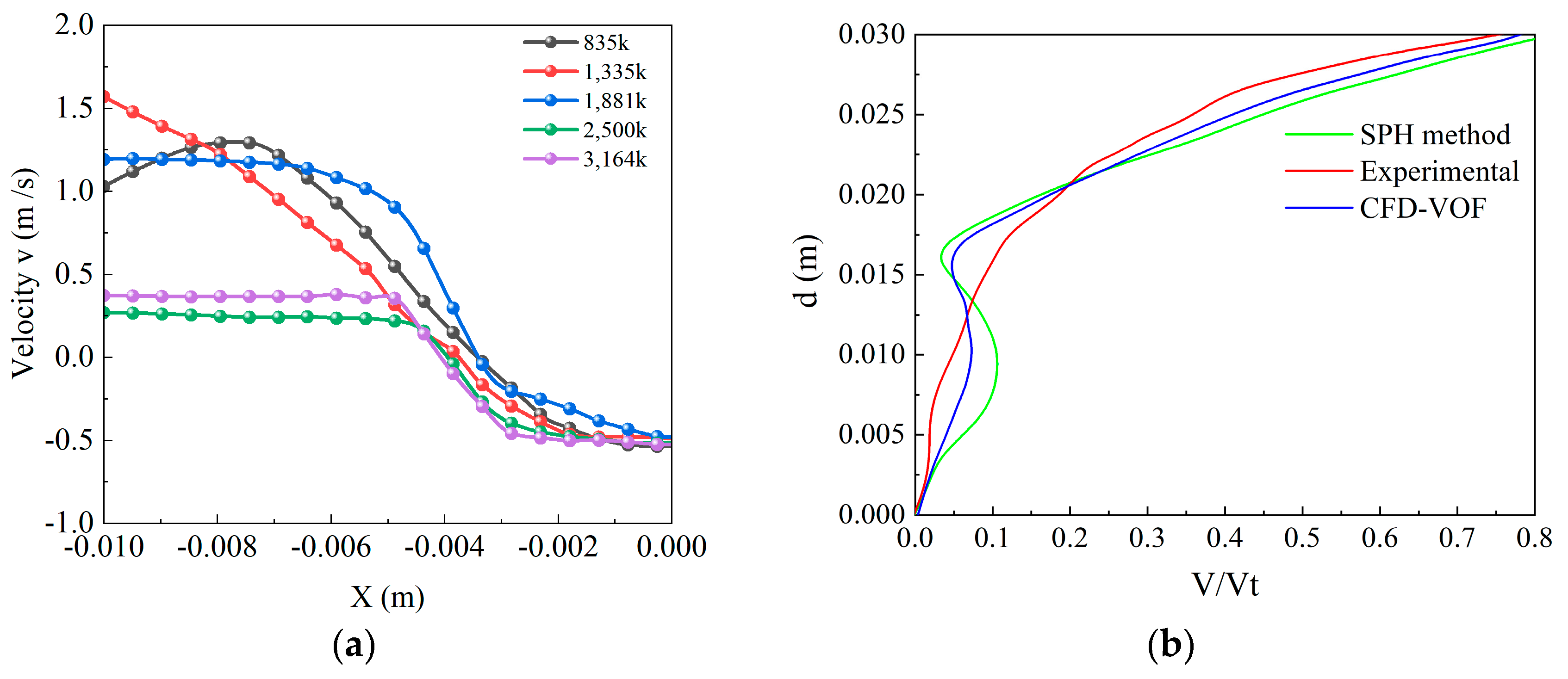
To assess the dependence of the proposed numerical model’s solution accuracy on mesh resolution while ensuring computational efficiency, this study conducted a mesh independence analysis. Five mesh densities were selected (835k, 1335k, 1881k, 2500k, and 3164k) to compare the velocity distribution in the gear center plane. Given the significant variation in flow velocity with spatial position in this plane, it is chosen as the key indicator for evaluating mesh independence. At lower mesh densities (835k, 1335k, and 1881k), the flow velocity distribution exhibited nonlinear variations. As the mesh density increased, when the mesh count reached 2500k and 3164k, the velocity distribution in the distance range of [−0.01 m, −0.006 m] stabilized, and only a decreasing trend is observed thereafter. Notably, the computational results for the 2500k mesh model showed a relative error of less than 3% compared to the 3164k mesh model, meeting the mesh independence requirement. Therefore, using a mesh count of 2500k ensures both computational efficiency and numerical solution accuracy effectively.
The mesh independence analysis verifies the accuracy of the numerical solution in this study. To further evaluate the acceptability of the error between the computational model and experimental data, this study compares the numerical results based on the same CFD-VOF framework with those obtained by Ji et al. using the Smoothed Particle Hydrodynamics (SPH) method [67]. Additionally, the reliability of the computational framework is directly validated using the experimental data reported by Ji et al. The relevant comparison results are shown in Figure 4b. To quantitatively analyze the difference between the numerical results and experimental data, the average absolute velocity of the oil in the central axis region of both the large and small gears (dimensionless, represented as V/Vt) is plotted. The results indicate that the CFD-VOF framework used in this study demonstrates better accuracy in predicting the oil velocity distribution compared to the SPH method. Particularly in the large gear region (V/Vt ≈ 0.1), the average velocity curve obtained using the SPH method shows a significant bending shift, while the CFD-VOF results align more closely with the experimental data. This discrepancy mainly arises from the CFD-VOF method’s superior accuracy in capturing the viscous dissipation effects in the near-wall region, thereby more realistically reflecting the actual flow field structure in that area.
In conclusion, the mesh independence analysis ensures the accuracy of the numerical solution process. Furthermore, the comparison with experimental results of the gearbox flow field velocity distribution from Ji et al. verifies the reliability of the computational method. The dual validation through mesh independence analysis and experimental data comparison ensures the credibility of the numerical model and its results presented in this study.

4. Numerical Results and Discussion

4.1. Influence of Injection Velocity on Tooth-Surface Lubrication

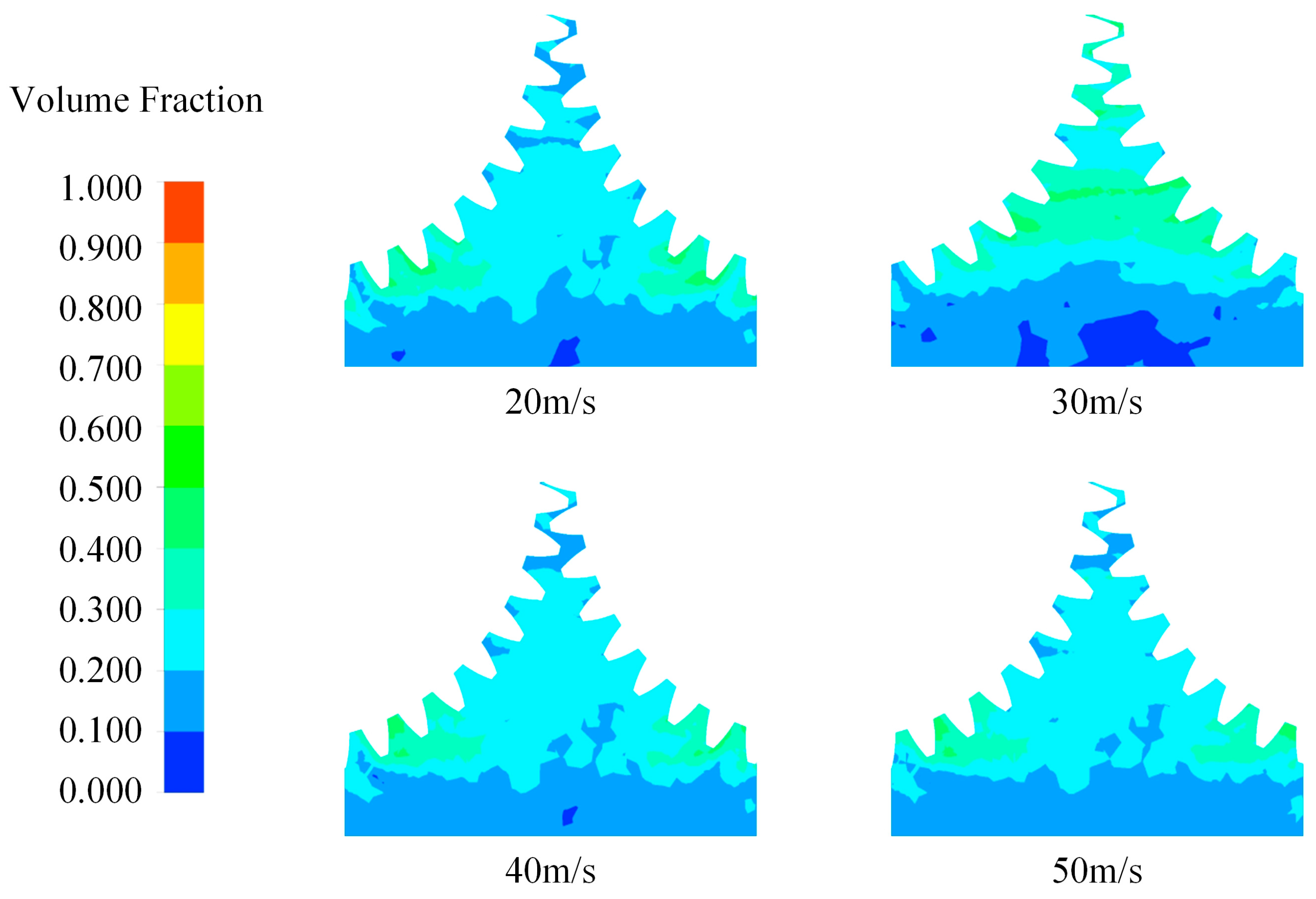
The injection velocity is a primary determinant of lubricant transport and, by extension, the quality of tooth-surface lubrication. The relationship between jet momentum and oil film development; however, is not yet fully characterized. To elucidate this coupling, a series of simulations is performed at a constant gear speed of 30 rad/s and a fixed nozzle height of 4.8 mm. Five inlet velocities—20, 30, 40, and 50 m/s—are prescribed, and the resulting oil-phase distributions are compared in Figure 5. The images highlight how increasing jet kinetic energy modifies film coverage and morphology across the meshing zone, thereby clarifying the role of injection velocity in directing lubricant to critical contact regions.
Numerical results demonstrate a pronounced, nonlinear influence of jet velocity on lubricant distribution in the gear mesh zone. At 20 m/s, local detachment appears on the crest and upper flanks, indicating that the jet still cannot maintain stable adhesion on the rapidly rotating surface. Optimal coverage emerges at 30 m/s, where the jet momentum and the oil’s surface-adhesion forces are balanced. Under these conditions, the lubricant wraps progressively along the tooth profile, creating a continuous film whose thickness gradually increases from the crest to the root and establishes an efficient channel in high-stress regions. Further increases to 40 m/s and 50 m/s reverse this improvement. The excess kinetic energy produces splashing and oil stripping, fragmenting the film and leaving dry zones on the crest and flanks. This finding indicates that once the jet’s kinetic energy becomes too high, lubrication efficiency no longer improves; instead, the weakened adhesion destabilizes the oil film, leading to its breakdown.
To advance the understanding of how oil-jet velocity influences both the spatial distribution of lubricant and the consequent lubrication quality on gear-tooth surfaces, the oil-volume fraction is examined. Within the tested range of 20·m/s to 50 m/s, the lubrication condition evolves non-linearly—first improving and then deteriorating as velocity rises, as shown in Figure 6. At the lower jet velocity of 20 m/s, the jet possesses limited kinetic energy; once impinging on the gear surface, gravity and viscous forces predominate. This enables a relatively uniform coating across the addendum, flank, and dedendum, albeit with an overall thin oil film due to insufficient momentum. Notably, a jet velocity of approximately 30 m/s establishes an optimal balance between jet impingement force and oil adhesion. Under this condition, the lubricant adheres and spreads effectively along the tooth profile, forming a continuous film with a thickness gradient from addendum to dedendum. Both the macroscopic coverage area and local film-thickness stability reach their maxima at this velocity. However, further elevating the jet velocity beyond 40 m/s endows the jet with excessive kinetic energy. Intense airflow shear and centrifugal forces rapidly strip the lubricant from the surface. Extensive dry zones emerge over the addendum and flank, while the residual film fractures into isolated patches. This process is accompanied by the ejection of fine oil droplets, which not only increases energy consumption but also elevates airborne noise levels.

4.2. Influence of Injection Velocity on Oil-Phase Volume Fraction

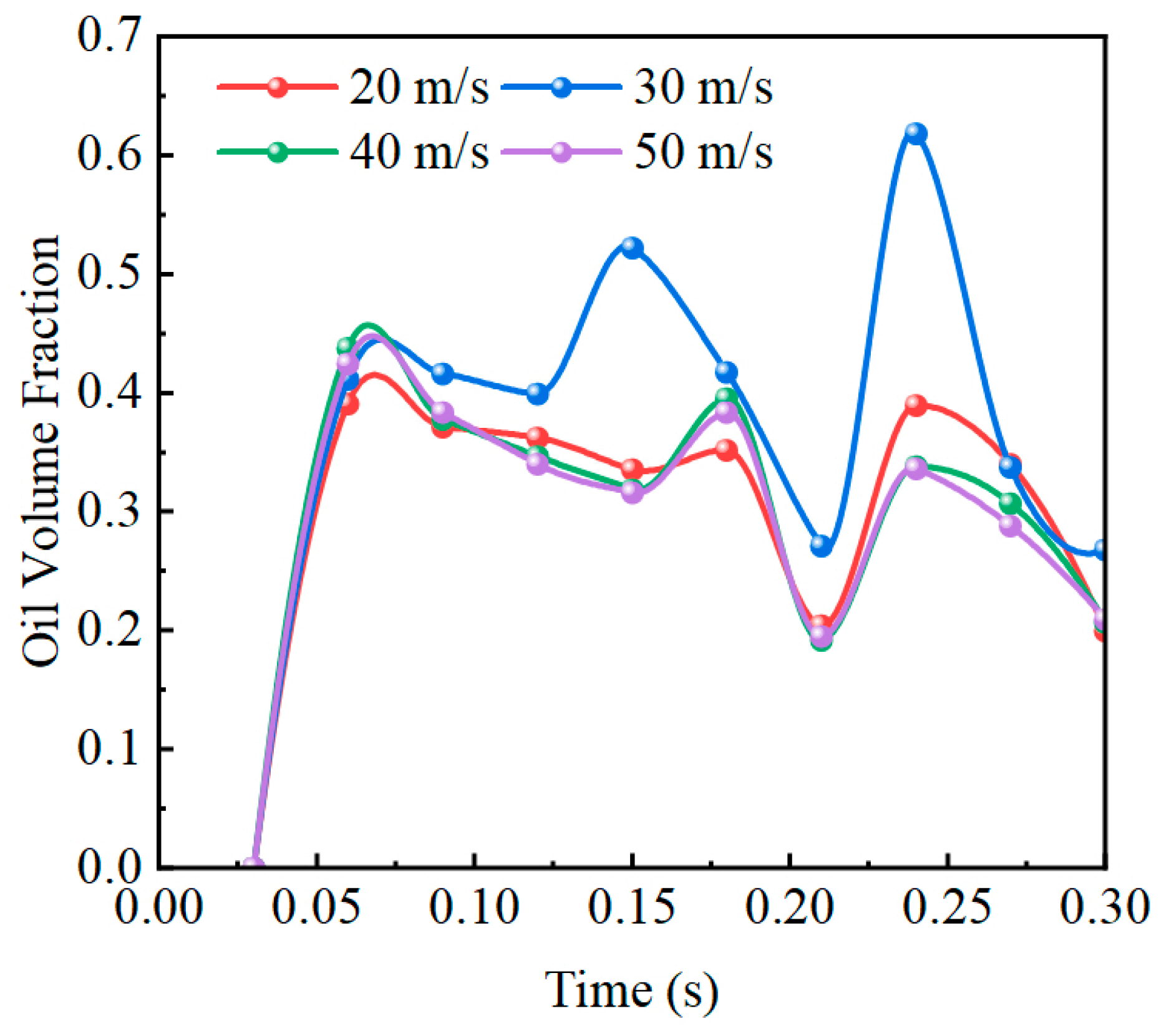
To quantify the observed distribution trends, the temporal evolution of the oil-phase volume fraction was monitored at point P on the tooth flank throughout successive meshing cycles, as shown in Figure 7. The curves obtained under various jet-velocity conditions corroborate the previously described behavior. At low velocities, the mean oil-phase volume fraction is comparatively high but exhibits pronounced fluctuations, reflecting a poorly stabilized lubricant film. At the intermediate velocity of 30 m/s, the mean value reaches its maximum while the fluctuation amplitude is minimized, indicating a continuous and stable oil film coverage. When the jet velocity is further increased, the signal periodically shows deep drops of growing magnitude and randomness, revealing a latent risk of intermittent dry contact on the tooth surface.
From a mechanistic standpoint, the jet velocity modifies the initial kinetic energy of the lubricant, thereby governing its transport pathways along the tooth surface. At low velocities, the insufficient momentum of individual droplets yields a stochastic, patchy distribution. An intermediate velocity (30 m/s) promotes the formation of well-defined migration channels, enabling directed spreading and the establishment of a coherent film. By contrast, at high velocities, complex gas–liquid interactions induced by the energetic jet disrupt the continuity of the film, triggering lubricant splashing. These findings identify an optimal jet-velocity window—centered on approximately 30 m/s—in which the oil stream overcomes aerodynamic resistance to achieve adequate coverage without incurring splash-related losses. The analysis provides a critical design parameter for gearbox lubrication systems, particularly for optimizing precision injection strategies under high-speed, heavy-load conditions.

4.3. Influence of Injection Velocity on Oil-Phase Viscosity

As depicted in Figure 8, incrementally raising the jet velocity simultaneously reorganizes the turbulence field and modifies the oil–air wetting pattern. At the velocity rises to 20 m/s and 30 m/s, eddy viscosity within the tooth spaces grows sharply. Stronger local shear lifts the oil film from the root, forming a continuous high-viscosity zone around point P that extends inward along the tooth flanks. Symmetric bands of intensified turbulence appear on both sides of the mesh line, and momentum dissipation increases markedly. At 40 m/s and 50 m/s, a “high-energy channel” spans the tooth tips. The combined action of the jet impact and inter-tooth vortices drives turbulent energy in a closed loop from the tooth flank to the root and down to the sump. A broad core of high eddy viscosity now occupies most inter-tooth passages and the oil collection region, repeatedly breaking the phase interface. Relative slip between oil and air intensifies, and the oil film becomes discontinuous and unstable. These observations demonstrate that higher jet speeds influence lubrication in two ways: they increase direct impingement on the tooth surface and, more importantly, amplify turbulent dissipation and shear instability, which redirect the oil–air mixture. The result is lower film coverage, poorer phase separation, and higher overall energy use. Hence, the design of high-speed gear systems must strike a balance—providing enough jet momentum for penetration while limiting the turbulence it induces—to optimize oil delivery, adhesion, and recirculation.
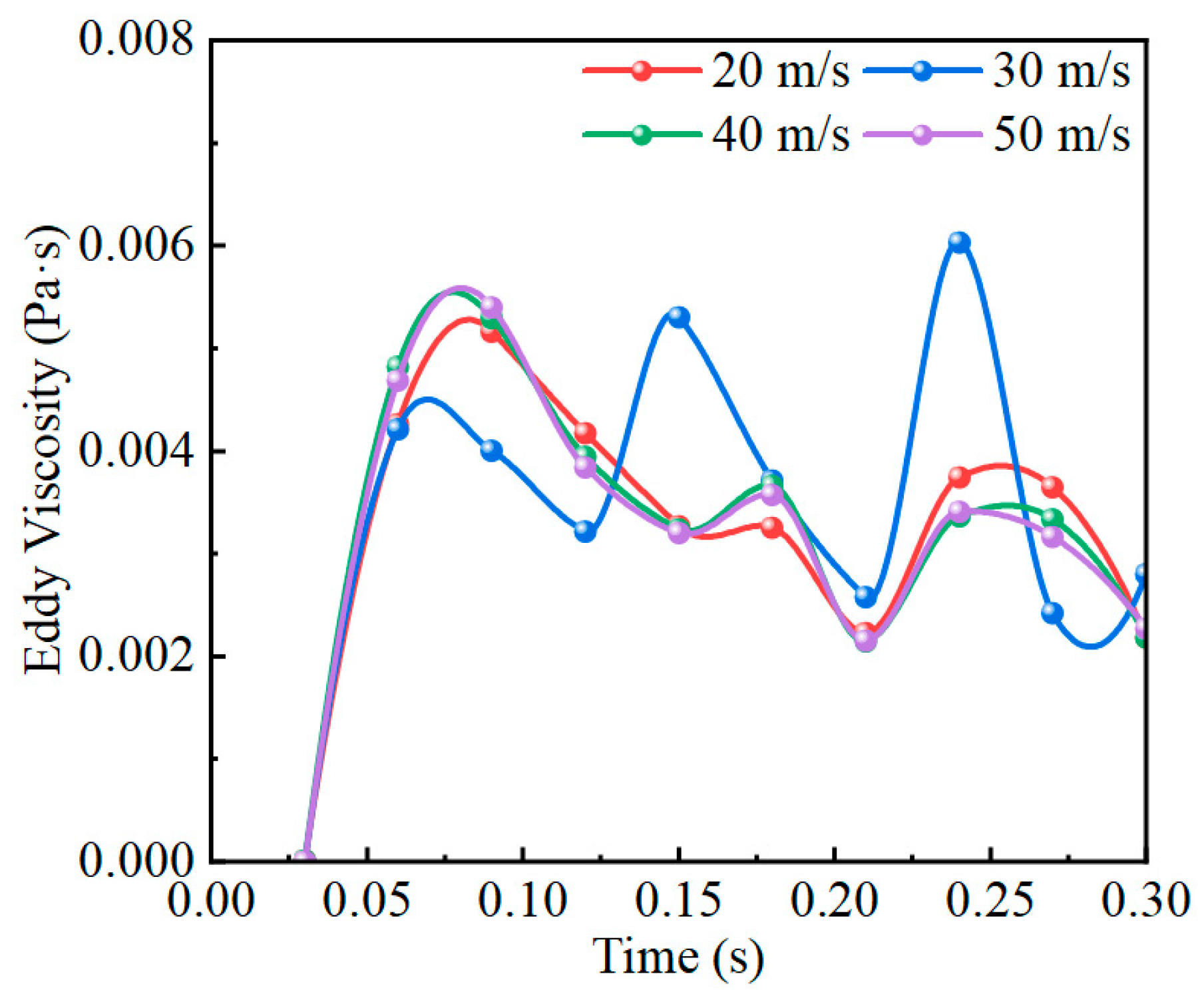
The temporal evolution of eddy viscosity at monitoring point P—located below the mesh line—is contrasted for jet velocities ranging from 20 m/s to 50 m/s, as shown in Figure 9. Around 0.03 s, all curves exhibit a sharp rise, marking the arrival of the first oil pulse at the tooth root. The sudden shear and cavitation-induced entrainment briefly elevate local turbulence. This initial peak rises with jet speed up to 30 m/s, where the interaction between the jet and the root back-flow yields the strongest shear coupling; at 40 m/s and 50 m/s, it drops again because the deeper-penetrating jet spends less time attached to the surface. Between 0.10 s and 0.30 s, the curves oscillate, reflecting the cyclic sweeping of oil into and away from point P. The 30 m/s case shows the largest amplitude, indicating vigorous break-up and re-attachment of the shear layer and, consequently, peak turbulent dissipation. At ≥40 m/s, the amplitudes shrink, confirming that excessive jet momentum suppresses local recirculation. After 0.28 s, the traces converge to roughly 0.003 Pa·s, implying that once a quasi-steady recirculation forms, the influence of jet speed is overshadowed by tooth-induced vortices near the casing floor. In sum, a jet velocity of about 30 m/s lies in the critical range that maximizes turbulence enhancement and oil redistribution at the root. Raising the speed further increases the overall oil supply but shortens residence time due to centrifugal fling-off, weakening shear coupling, and reducing the eddy-viscosity contribution at point P. The spray strategies should therefore center on this threshold to balance penetration, residence, and recirculation.

4.4. Influence of Injection Velocity on Turbulent Kinetic Energy

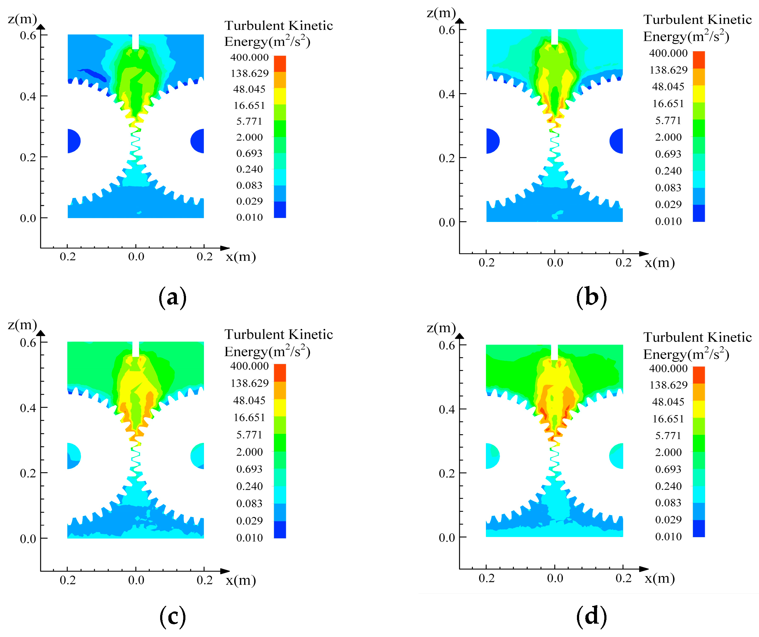
Turbulence intensity governs how the oil behaves inside a gearbox. Figure 10 maps the spatial distribution of turbulent kinetic energy, k, as the jet velocity rises stepwise from 20 m/s to 50 m/s. At 20 m/s, a narrow, column-shaped core forms between the nozzle and the tooth-tip clearance. Shielded by the rotating air curtain, its energy dissipates quickly and barely reaches the mesh. Raising the velocity to 20 m/s and 30 m/s elevates the core momentum: a yellow high-k zone pushes deeper, touches the tooth crest, and fans out in a trumpet shape along the flank, promoting oil breakup and entrainment. At 40 m/s and 50 m/s, the peak k jumps above 138 m2/s2. The upper chamber becomes filled with high-energy fluid, while stair-stepping penetration channels appear between the crest, root, and housing roof, establishing a fast-recirculating loop. The sump, however, remains primarily blue (low k), acquiring only sparse green patches at 50 m/s—evidence that even very high jet speeds leave the root region largely under-energized. Overall, kinetic energy expansion and tooth–flank coupling increase with velocity up to 30 m/s; beyond that, the field enters a saturation regime where turbulence intensifies at the top but yields limited improvement below the mesh. Thus, if the goal is to effectively wet the mesh clearance, designers must balance jet depth with where the energy is dissipated rather than simply pursuing extreme speeds.
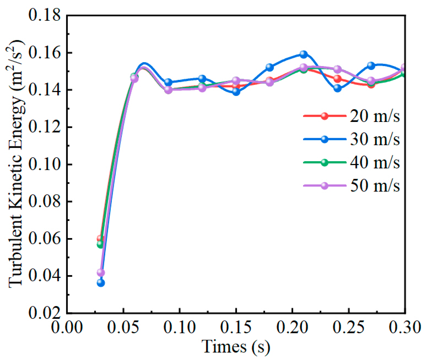
To quantitatively characterize the temporal evolution of turbulent kinetic energy (k) within the meshing zone, a time-resolved record is extracted at monitoring point P, as depicted in Figure 11. During the first 0.02 s, all velocity cases exhibit a common rapid escalation to approximately 0.12–0.14 m2/s2, indicating that the incipient jet momentum, after inter-tooth shear coupling, simultaneously excites an instability in the near-root flow; at this stage, gear-induced recirculation rather than jet-speed differences governs the response. Beyond 0.05 s, the curves diverge: for 30 m/s and 40 m/s, the mean k stabilizes at 0.15–0.16 m2/s2 and exhibits the highest local peaks, demonstrating that moderate-to-high jet momentum both penetrates the crest air curtain and interacts strongly with root entrainment, thereby amplifying local shear and turbulence. In contrast, the 20 m/s cases plateau near 0.13–0.14 m2/s2, confirming that low-momentum jets lack sufficient energy to sustain recirculation at the root. Increasing the velocity to 50 m/s offers no additional benefit; between 0.10 s and 0.25 s, the average k marginally underperforms the 40 m/s case because centrifugal fling-off shortens surface residence time and dissipates energy near the crest rather than transmitting it to point P. Collectively, these results identify 30–40 m/s as the optimal velocity window: it ensures adequate jet penetration while maintaining a high, quasi-steady k level at the root, thereby facilitating continuous film breakup and redistribution. Outside this interval, energy utilization efficiency declines, indicating that spray strategies should balance total oil delivery against local turbulence excitation.

4.5. Influence of Injection Velocity on Oil Velocity

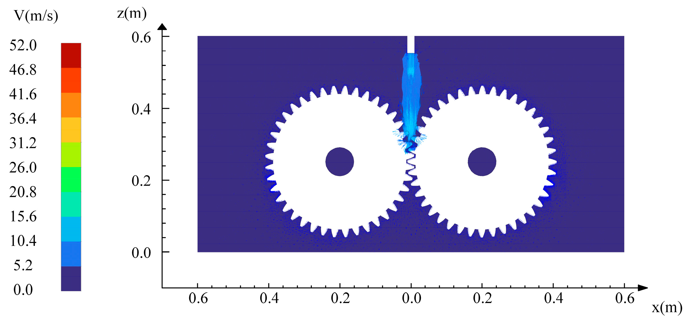
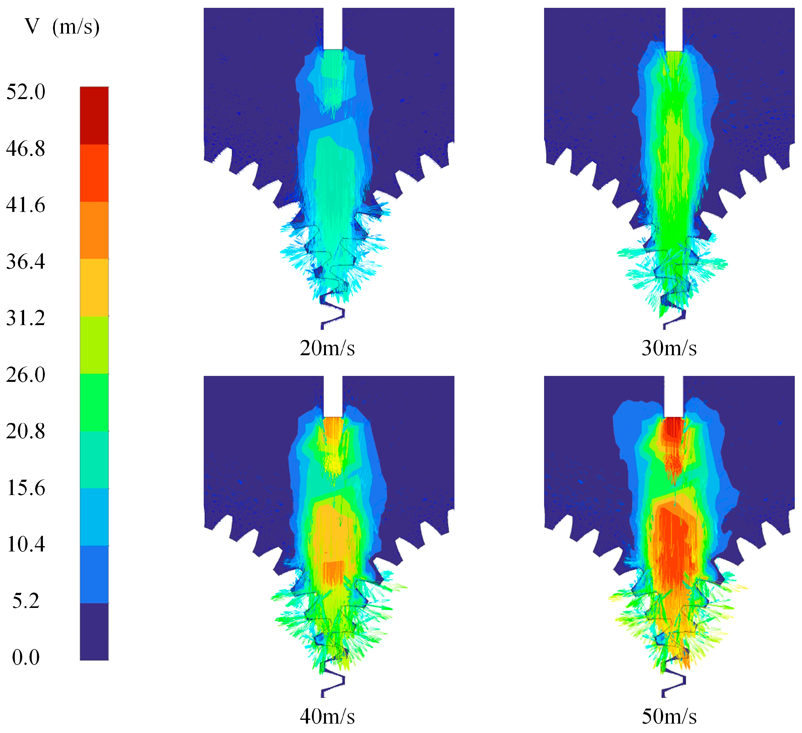
To further quantify the effect of nozzle speed on oil-jet behavior, instantaneous velocity fields were compared across the entire velocity range, as shown in Figure 12. At low injection speeds, the jet retains a compact core: its momentum quickly dissipates, the velocity field remains spatially confined, and the stream reaches the mesh with much of its energy already lost. Consequently, the jet imparts only a moderate, low-speed impingement. As the injection speed increases, both the spatial reach and peak velocity of the jet expand markedly. At 30 m/s, the core broadens and penetrates deeper into the gear cavity, while higher velocities (40–50 m/s) produce a wide, high-energy plume that sweeps a substantially larger sector. The attendant rise in axial velocity minimizes in-flight energy loss and enables a more forceful, rapid transfer of momentum to the tooth surfaces. This high-speed, wide-dispersion jet promotes more uniform surface coverage—an advantage for lubrication, cleaning, and related applications—provided that the associated turbulence and splash are compatible with system constraints.
The time-resolved oil velocity at point P increases along the positive Y-axis immediately after jet impingement, driven by the momentum of the incoming flow, as shown in Figure 13. The resulting peak velocity increases almost linearly with injection speed, climbing from roughly 0.05 m/s at 20 m/s to about 0.35 m/s at 50 m/s, underscoring the jet’s strong local driving effect. During the next 0.02–0.05 s, gravity, reverse airflow from gear meshing, and turbulent dissipation combine to decelerate the flow, drive it through zero, and create a negative extreme near –0.5 m/s. The timing of this minimum is essentially insensitive to injection speed, indicating that the geometry of the inter-tooth passage and centrifugal forces dominate the return flow. Beyond 0.05 s, the velocity oscillates between –0.15 m/s and –0.25 m/s before settling toward a quasi-steady state. Both the amplitude and frequency of these oscillations grow with injection speed: at speeds of 30 m/s or higher, the curve exhibits larger swings and higher-frequency jitter, showing that high-momentum jets excite stronger vortices and more vigorous redistribution near the tooth root, thereby intensifying the cyclic exchange of momentum and turbulent energy. Although higher injection speeds deliver greater initial momentum, they also introduce stronger flow unsteadiness and shear imbalance. Effective lubrication, therefore, requires balancing momentum supply against flow-field stability, making injection velocity a critical design parameter for optimizing gear lubrication systems.
As the oil-jet velocity is progressively increased within a prescribed range, the flow speed of the oil film along the gear-mesh surfaces accelerates accordingly, thereby entraining a larger quantity of lubricant into the meshing tooth clearances. At elevated injection rates, the velocity-vector field demonstrates that the lubricant spreads more extensively not only across the normal plane at the gear end face but also within the tooth gaps, where both volumetric flux and local velocity rise appreciably.
Figure 14 also shows that the lubricant velocity at monitoring point P exhibits pronounced temporal dynamics. In the initial injection stage, the velocity increases rapidly to a peak, then drops precipitously due to aerodynamic drag, and finally enters an oscillatory regime. This behavior is intrinsically linked to jet hydrodynamics: at lower injection speeds, insufficient kinetic energy produces weak velocity fluctuations. As the speed rises, the high-momentum jet experiences the combined influences of aerodynamic drag, inertia, and tooth-surface reflections, greatly amplifying velocity oscillations. Thus, injection speed is a pivotal control variable that not only determines the lubricant’s initial kinetic energy but also governs energy dissipation and redistribution during spatial propagation. Notably, higher injection velocities intensify the jet’s unsteady character, increasing both the frequency and amplitude of velocity fluctuations and, therefore, exert a critical impact on the transient performance of the lubrication system.
In summary, injection velocity exerts a decisive influence on the transient characteristics of the lubricant velocity field. While increasing the velocity enhances the lubricant’s initial momentum and improves penetration into key regions, it concurrently accentuates unsteady behavior within the jet. This amplified fluctuation may enhance lubricant infiltration, yet it can also cause local velocity overloads that risk lubrication failure. Consequently, optimization of injection parameters requires a balanced consideration of injection velocity and lubricant hydrodynamics to maximize overall system performance.
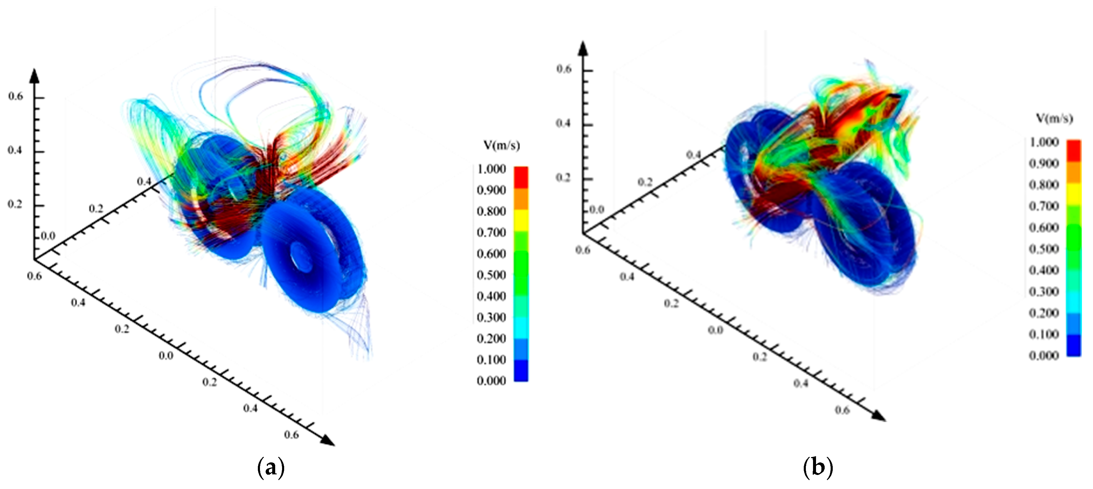
To further elucidate the relationship between injection distance and lubricant hydrodynamics, Figure 15 presents detailed streamline distributions obtained at injection velocities of 20 m/s and 30 m/s. When the injection velocity is 20 m/s, only a portion of the oil successfully penetrates the meshing region after striking the gears; the remainder, lacking sufficient kinetic energy, rebounds toward the outer periphery, producing a highly dispersed distribution, as shown in Figure 15a. The resulting flow outside the gear rim is disordered and fails to form a stable lubricating film, offering limited benefit to overall system performance. By contrast, raising the velocity to 30 m/s markedly enhances the oil’s momentum, yielding clearer and more organized streamlines, as shown in Figure 15b. After impact, the lubricant penetrates more deeply into the tooth gaps, and streamline density on the gear flanks increases substantially, indicating greater surface coverage and improved film formation. The oil now impinges at high speed, driving vigorously into the inter-tooth clearances and forming intense, coherent flow channels. This concentrated, high-efficiency transport accelerates the establishment of a robust lubricating film and thus promotes highly effective lubrication. These results demonstrate that injection velocity critically governs lubricant dynamics in gear systems. Appropriately adjusting this parameter can optimize oil distribution and flow characteristics, thereby improving lubrication. Low velocities lead to pronounced dispersion and rebound, yielding poor lubrication; moderate velocities enhance coverage and flowability, improving operating conditions; high velocities focus the lubricant on key regions, rapidly forming a stable film. Hence, practical lubrication-system design and operation must precisely control injection velocity following specific operating conditions and equipment requirements, so as to maximize lubricant performance and ensure stable, high-efficiency gear operation. The present findings provide a strong basis for optimizing injection-system design and regulating lubricant dynamics, offering substantial practical value for enhancing injection efficiency, reducing energy consumption, and achieving more precise control.

5. Conclusions

The dynamics of gear lubrication significantly impact the reliability and efficiency of high-speed, heavy-load transmission systems. This paper proposes a numerical simulation framework that integrates CFD-VOF and dynamic mesh technology to analyze the lubrication flow mechanisms comprehensively. Through systematic research, the following conclusions are drawn:
  • A transient multiphase flow model of gear lubrication is established based on the CFD-VOF coupled approach. Combined with dynamic mesh and adaptive refinement technologies, the model accurately captures key physical phenomena, including oil film formation, jet impingement, turbulent interactions, and phase interface evolution, thereby revealing the dynamic coupling mechanisms of lubricant transport at varying injection velocities.
  • With increasing injection velocity, lubrication effectiveness first enhances and then deteriorates, exhibiting a clear optimal range of approximately 30 m/s. Lower injection velocities fail to generate sufficient kinetic energy, resulting in discontinuous lubrication films. Moderate velocities enable stable and continuous oil film coverage, achieving optimal lubrication. Higher velocities, however, induce pronounced oil splashing and film detachment, resulting in decreased lubrication efficiency.
  • Turbulence characteristics and oil transport patterns exhibit significant velocity-dependent variability. As jet velocity increases, turbulence kinetic energy and eddy viscosity intensify, reaching peak local shear and turbulence effects around 30 m/s. Beyond this range, excessive turbulence exacerbates oil flow instability, causing substantial fluctuations in both oil velocity and phase distribution. Consequently, excessively high velocities diminish lubricant adhesion and amplify energy losses.
  • Flow visualization reveals distinct modes of oil transport under varying injection velocities. At lower velocities, the lubricant flow is dispersed and significantly rebounds, impeding effective lubrication. At moderate velocity (30 m/s), coherent, adequate lubricant transport occurs, effectively penetrating gear teeth clearances and enhancing lubrication. Although high velocity (50 m/s) concentrates oil transport, the increased risks of splash and energy loss significantly compromise the effectiveness of lubrication.

6. Future Work

Although the present study has successfully established a validated computational framework for analyzing oil-jet lubrication dynamics in high-speed gear systems, several directions remain open for further exploration in order to enhance the model’s fidelity, applicability, and predictive capability. A promising avenue lies in the adoption of advanced turbulence modeling techniques. Scale-resolving approaches such as Large Eddy Simulation (LES) or hybrid RANS-LES frameworks offer the potential to capture transient flow structures, including coherent vortices, interfacial instabilities, and anisotropic turbulence effects, which are often inadequately represented by traditional Reynolds-Averaged Navier–Stokes (RANS) models such as the SST k-ω formulation. This is particularly relevant under ultra-high-speed conditions-exceeding 50 m/s-where turbulent energy transfer mechanisms become increasingly nonlinear and strongly directional.
Incorporating thermo-fluid coupling into the simulation framework represents an important step toward a more realistic representation of lubrication behavior. Integration of conjugate heat transfer models alongside viscous dissipation effects enables evaluation of the impact of localized thermal gradients on lubricant viscosity, especially under long-duration or high-load operating regimes. Thermal effects influence film integrity, potentially accelerating oil film collapse or altering shear-thinning behavior, which in turn affect gear contact performance and wear characteristics. Experimental validation remains a critical component for advancing numerical accuracy and model credibility. High-speed Particle Image Velocimetry (PIV) provides time-resolved flow field measurements within the oil–air domain, capturing jet breakup, dispersion, and entrainment phenomena. Complementary infrared thermographic imaging of gear tooth surfaces enables spatially resolved temperature field acquisition, offering a quantitative basis for validating predictions of lubricant film distribution and localized shear heating. Extension of the proposed modeling framework to more complex gear configurations as planetary and bevel gear systems broadens its practical relevance. Integration of real-time optimization strategies, potentially involving data-driven algorithms like reinforcement learning for adaptive injection control, improves lubrication efficiency and reliability under dynamically varying speed and load conditions. These research directions contribute to the development of next-generation gear lubrication technologies, aligned with ongoing trends in digital twin engineering and intelligent control of tribological systems.

Author Contributions

Conceptualization, Y.G. and Q.Y.; methodology, Y.G.; software, Q.Y.; validation, Y.G., L.L. and X.Z.; formal analysis, Y.G.; investigation, Y.G.; resources, Y.G.; data curation, Y.G.; writing—original draft preparation, Y.G.; writing—review and editing, Y.G.; visualization, Y.G.; supervision, Y.G.; project administration, Q.Y.; funding acquisition, Y.G. All authors have read and agreed to the published version of the manuscript.

Funding

This research received no external funding.

Data Availability Statement

The original contributions presented in this study are included in the article. Further inquiries can be directed to the corresponding author.

Conflicts of Interest

The authors declare no conflicts of interest.

References

  1. Li, Z.; Wang, C.Y.; Wu, J.F.; Yin, Z.C.; Tan, D.P. Numerical investigation of mesoscale multiphase mass transport mechanism in fibrous porous media. Eng. Appl. Comput. Fluid Mech. 2024, 18, 2363246. [Google Scholar] [CrossRef]
  2. Yang, X.; Zhang, Z.; Zhang, T.; Song, F.; Yao, X.; Xiao, B.; Lin, P.; Qi, H.; Liu, S.; Tang, H. Multi-build orientation effects on microstructural evolution and mechanical behavior of truly as-built selective laser melting Ti6Al4V alloys. J. Mater. Res. Technol. 2024, 30, 3967–3976. [Google Scholar] [CrossRef]
  3. Li, L.; Tan, Y.; Xu, W.; Ni, Y.; Yang, J.; Tan, D. Fluid-induced transport dynamics and vibration patterns of multiphase vortex in the critical transition states. Int. J. Mech. Sci. 2023, 252, 108376. [Google Scholar] [CrossRef]
  4. Chen, H.; Wan, H.; Hong, B.; Hang, W.; Zhu, T.; Zhang, P.; Cao, X.; Xu, Q.; Wang, R.; Han, X.; et al. A novel liquid film shearing polishing technique for silicon carbide and its processing damage mechanisms. Appl. Surf. Sci. 2025, 688, 162317. [Google Scholar] [CrossRef]
  5. Li, L.; Lu, B.; Xu, W.X.; Gu, Z.H.; Yang, Y.S.; Tan, D.P. Mechanism of multiphase coupling transport evolution of free sink vortex. Acta Phys. Sin. 2023, 72, 034702. [Google Scholar] [CrossRef]
  6. Li, Q. Transport Mechanism and Optimization Design of LBM-LES Coupling-Based Two-Phase Flow in Static Mixers. Processes 2025, 130, 1666. [Google Scholar]
  7. Li, L.; Xu, W.X.; Tan, Y.F.; Yang, Y.S.; Yang, J.G.; Tan, D.P. Fluid-induced vibration evolution mechanism of multiphase free sink vortex and the multi-source vibration sensing method. Mech. Syst. Signal Process. 2023, 189, 110058. [Google Scholar] [CrossRef]
  8. Lu, W.; Zhang, Y.; Cheng, H.; Zhou, Y.; Lv, H. Research on dynamic behavior of multistage gears-bearings and box coupling system. Measurement 2020, 150, 107096. [Google Scholar] [CrossRef]
  9. Li, L.; Li, Q.; Xu, P.; Zheng, R.Y.; Yin, Z.C.; Bao, J.J.; Yang, Y.S.; Tan, D.P. Multiscale heat transfer mechanism and dynamic regulation of free-surface swirling flow based on LBM-LES coupling. Appl. Therm. Eng. 2025, 150, 107096. [Google Scholar]
  10. Li, L.; Xu, P.; Li, Q.H.; Zheng, R.Y.; Xu, X.M.; Wu, J.F.; He, B.Y.; Bao, J.J.; Tan, D.P. A coupled LBM-LES-DEM particle flow modeling for microfluidic chip and ultrasonic-based particle aggregation control method. Appl. Math. Model. 2025, 143, 116025. [Google Scholar] [CrossRef]
  11. Morhard, B.; Paschold, C.; Lohner, T.; Stahl, K. Power loss and damage behavior of gears operating under loss of lubrication. J. Tribol. 2024, 146, 072201. [Google Scholar] [CrossRef]
  12. Li, L.; Xu, P.; Li, Q.H.; Yin, Z.C.; Zheng, R.Y.; Wu, J.F.; Bao, J.J.; Qi, H.; Tan, D.P. Multi-field coupling particle flow dynamic behaviors of the microreactor and ultrasonic control method. Powder Technol. 2025, 454, 120731. [Google Scholar] [CrossRef]
  13. Lu, R.; Tang, W.; Huang, Q.; Xie, J. An improved load distribution model for gear transmission in thermal elastohydrodynamic lubrication. Lubricants 2023, 11, 177. [Google Scholar] [CrossRef]
  14. Gu, Y.; Zheng, G. Study on the dynamic characteristics of the gear lubrication flow field with baffles and optimization design strategies. Lubricants 2025, 13, 143. [Google Scholar] [CrossRef]
  15. Zhang, Y.; Wang, Y.; Lu, B. Thermal elastohydrodynamic lubrication of herringbone gear considering the effect of oil gas mixture. J. Therm. Sci. Eng. Appl. 2023, 15, 061003. [Google Scholar] [CrossRef]
  16. Liu, M.; Han, X.; Yan, C.; Ouyang, Z.; Qi, D. Tribological characteristics evaluation of a helical gear pair based on the tribo-dynamic model. Lubr. Sci. 2023, 35, 616–635. [Google Scholar] [CrossRef]
  17. Yan, Q.; Fan, X.H.; Li, L.; Zheng, G.A. Investigations of the Mass Transfer and Flow Field Disturbance Regulation of the Gas-Liquid-Solid Flow of Hydropower Stations. J. Mar. Sci. Eng. 2024, 12, 84. [Google Scholar] [CrossRef]
  18. Tong, W.J. Analysis of Flow Field and Machining Parameters in RUREMM for High-precision Micro-texture Fabrication on SS304 Surfaces. Processes 2025, 13, 2326. [Google Scholar] [CrossRef]
  19. Tan, Y.F.; Ni, Y.S.; Xu, W.X.; Xie, Y.S.; Tan, D.P. Key technologies and development trends of the soft abrasive flow finishing method. J. Zhejiang Univ. Sci. A 2023, 24, 1043–1064. [Google Scholar] [CrossRef]
  20. Wang, C.Y.; Li, Z.; Xu, P.; Hou, Y.Q.; Tan, D.P. Collision modelling approach and transient response mechanism of ring-ribbed cylindric shells for underwater vehicles. Appl. Math. Model. 2025, 141, 115923. [Google Scholar] [CrossRef]
  21. Wang, L.; Hong, B.; Chen, H.; Qi, H.; Zhang, J.; Hang, W.; Han, Y.; Wang, J.; Ren, K.; Lyu, B. Enhancing Tungsten Machinability via Laser Pretreatment for Abrasive Particles-based Shear Rheological Polishing. Powder Technol. 2025, 455, 120758. [Google Scholar] [CrossRef]
  22. Zheng, G.A.; Xu, P. Investigate on the Fluid Dynamics and Heat Transfer Behavior in an Automobile Gearbox Based on the LBM-LES Model. Lubricants 2025, 13, 117. [Google Scholar] [CrossRef]
  23. Li, Z.; Wang, C.; Li, L.; Wu, J.; Xie, Y.; Tan, D. Mechanism of multiphase flow transport in laterally-compressed cathode channels with fin-type obstacles for PEMFC. Appl. Therm. Eng. 2025; in press. [Google Scholar]
  24. Ni, Y.; Li, Q.; Tan, Y.; Yu, J.; Yuan, J.; Tan, D. Multi-physical coupling modeling and ultrasonic crack detection mechanism analysis for underwater steel structures. Ocean. Eng. 2025; in press. [Google Scholar]
  25. Li, X.; Shao, W.; Tang, J.; Zhang, D.; Chen, J.; Zhao, J.; Wen, Y. Multi-physics field coupling interface lubrication contact analysis for gear transmission under various finishing processes. Eng. Fail. Anal. 2024, 165, 108742. [Google Scholar] [CrossRef]
  26. Chen, G.; Zhou, Y.; Qian, X.; Wu, W.; Zhao, Y.; Hu, Y. Simulation study of oil-jet lubrication for high-speed gears. Lubr. Eng. 2019, 44, 125–132. [Google Scholar]
  27. Keller, M.; Kromer, C.; Cordes, L.; Schwitzke, C.; Bauer, H.-J. CFD study of oil-jet gear interaction flow phenomena in spur gears. Aeronaut. J. 2020, 124, 1301–1317. [Google Scholar] [CrossRef]
  28. Dai, Y.; Ma, F.; Zhu, X.; Su, Q.; Hu, X. Evaluation and optimization of the oil jet lubrication performance for orthogonal face gear drive: Modelling, simulation and experimental validation. Energies 2019, 12, 1935. [Google Scholar] [CrossRef]
  29. Wang, Y.; Song, G.; Niu, W.; Chen, Y. Influence of oil injection methods on the lubrication process of high-speed spur gears. Tribol. Int. 2018, 121, 180–189. [Google Scholar] [CrossRef]
  30. Jiang, X.; Zhou, C.; Su, J.; Jin, G.; Shen, R. Injection parameter design to improve the high-speed gear heat dissipation: CFD simulation and regression orthogonal experiment. Simul. Model. Pract. Theory 2023, 128, 102795. [Google Scholar] [CrossRef]
  31. Hu, X.; Li, P.; Quan, C.; Wang, J. CFD investigation on oil injection lubrication of meshing spur gears via lattice Boltzmann method. Lubricants 2022, 10, 184. [Google Scholar] [CrossRef]
  32. Wu, W.; Wei, C.; Yuan, S. Numerical simulation of ball bearing flow field using the moving particle semi-implicit method. Eng. Appl. Comput. Fluid Mech. 2022, 16, 215–228. [Google Scholar] [CrossRef]
  33. Hu, X.; Jiang, Y.; Luo, C.; Feng, L.; Dai, Y. Churning power losses of a gearbox with spiral bevel geared transmission. Tribol. Int. 2019, 129, 398–406. [Google Scholar] [CrossRef]
  34. Boni, J.-B.; Neurouth, A.; Changenet, C.; Ville, F. Experimental investigations on churning power losses generated in a planetary gear set. J. Adv. Mech. Des. Syst. Manuf. 2017, 11, 00196. [Google Scholar] [CrossRef]
  35. Jiang, Y.; Hu, X.; Hong, S.; Li, P.; Wu, M. Influences of an oil guide device on splash lubrication performance in a spiral bevel gearbox. Tribol. Int. 2019, 136, 155–164. [Google Scholar] [CrossRef]
  36. Concli, F.; Mastrone, M.N. Advanced lubrication simulations of an entire test rig: Optimization of the nozzle orientation to maximize the lubrication capability. Lubricants 2023, 11, 300. [Google Scholar] [CrossRef]
  37. Li, Q.; Xu, P.; Li, L.; Xu, W.; Tan, D. Investigation on the Lubrication Heat Transfer Mechanism of the Multilevel Gearbox by the Lattice Boltzmann Method. Processes 2024, 12, 381. [Google Scholar] [CrossRef]
  38. Gao, S.; Hou, X.; Ma, C.; Yang, Y.; Li, Z.; Yin, R.; Zhu, R. Transient simulation analysis of needle roller bearing in oil jet lubrication and planetary gearbox lubrication conditions based on computational fluid dynamics. Lubricants 2024, 12, 39. [Google Scholar] [CrossRef]
  39. Lu, B.; Xu, W.X.; Wang, C.Y.; Wu, J.F.; Tan, D.P. Dynamic behaviors of multiphase vortex-induced vibration for hydropower energy conversion. Energy 2024, 308, 132897. [Google Scholar] [CrossRef]
  40. Zhang, H.S.; Tan, D.P.; Xu, S.C.; HU, T.C.; Qi, H.; Li, L. Investigation of Crack Propagation and Failure of Liquid-Filled Cylindrical Shells Damaged in High-Pressure Environments. J. Mar. Sci. Eng. 2024, 12, 921. [Google Scholar] [CrossRef]
  41. Zhou, L.; Zhang, A.; Ding, S.; Han, S.; Li, F.; Kujala, P. Numerical Study of the Cavitation Performance of an Ice-Blocked Propeller Considering the Free Surface Effect. Water 2024, 16, 3260. [Google Scholar] [CrossRef]
  42. Sun, Z.; Yao, Q.; Jin, H.; Xu, Y.; Hang, W.; Chen, H.; Li, K.; Shi, L.; Gu, J.; Zhang, Q.; et al. A novel in-situ sensor calibration method for building thermal systems based on virtual samples and autoencoder. Energy 2024, 297, 131314. [Google Scholar] [CrossRef]
  43. Wang, W.-W.; Song, J.; Chen, Z.-D.; Lv, Z.-H.; Li, B.; Yang, H.-F.; Cai, Y.; Zhao, F.-Y. Two-phase closed thermosiphon with grooved the evaporator section applied for low-grade energy recovery: Thermo-hydrodynamic performance and potentials. Int. J. Therm. Sci. 2025, 208, 109416. [Google Scholar] [CrossRef]
  44. Li, L.; Xu, P.; Xu, W.X.; Wang, C.Y.; Tan, D.P. Multi-field coupling vibration patterns of the multiphase sink vortex and distortion recognition method. Mech. Syst. Signal Process. 2024, 219, 111624. [Google Scholar] [CrossRef]
  45. Xu, P.; Li, Q.H.; Wang, C.Y.; Tan, D.P.; Wu, H.P. Interlayer healing mechanism of multipath deposition 3D printing models and interlayer strength regulation method. J. Manuf. Process. 2025, 141, 1031–1047. [Google Scholar] [CrossRef]
  46. Yin, Z.C.; Lu, J.F.; Wang, T.; Wang, R.H.; Fan, X.H.; Lin, H.K.; Huang, Y.S.; Tan, D.P. Optimized Scheme for Accelerating the Slagging Reaction and Slag-Metal-Gas Emulsification in a Basic Oxygen Furnace. Appl. Sci. 2020, 10, 5101. [Google Scholar] [CrossRef]
  47. Zhou, C.; Jiang, X.; Su, J.; Liu, Y.; Hou, S. Injection lubrication for high-speed helical gears using the overset mesh method and experimental verification. Tribol. Int. 2022, 173, 107642. [Google Scholar] [CrossRef]
  48. Tan, D.; Yin, Z.; Wang, T.; Fan, X.; Wang, R. Investigation on the multiphase vortex and its fluid-solid vibration characters for sustainability production. Renew. Energy 2021, 175, 887–909. [Google Scholar] [CrossRef]
  49. Hu, X.; Wang, A.; Li, P.; Wang, J. Influence of dynamic attitudes on oil supply for bearings and churning power losses in a splash lubricated spiral bevel gearbox. Tribol. Int. 2021, 159, 106951. [Google Scholar] [CrossRef]
  50. Srinivasan, C.; Yang, X.; Schlautman, J.; Wang, D.; Gangaraj, S. Conjugate heat transfer CFD analysis of an oil cooled automotive electrical motor. SAE Int. J. Adv. Curr. Pract. Mobil. 2020, 2, 1741–1753. [Google Scholar] [CrossRef]
  51. Li, L.; Gu, Z.H.; Xu, W.X.; Tan, Y.F.; Fan, X.H.; Tan, D.P. Mixing mass transfer mechanism and dynamic control of gas-liquid-solid multiphase flow based on VOF-DEM coupling. Energy 2023, 272, 127015. [Google Scholar] [CrossRef]
  52. Xie, C.; Yu, W. Gear dynamic modelling based on the concept of dynamic mesh stiffness: Theoretical study and experimental verification. J. Mech. Sci. Technol. 2022, 36, 4953–4965. [Google Scholar] [CrossRef]
  53. Shi, D.; Zhang, Y.; Zhang, H.; Hou, X. Analysis of two-phase flow fields and spray lubrication characteristics of high-speed gears. J. Mech. Transm. 2024, 48, 1–8. [Google Scholar]
  54. de Bie, V.G.; Spanjaards, M.M.; Hulsen, M.A.; Anderson, P.D. The extrusion of EPDM using an external gear pump: Experiments and simulations. Int. Polym. Process. J. Polym. Process. Soc. 2022, 37, 452–468. [Google Scholar] [CrossRef]
  55. Li, Q.H.; Ni, Y.S.; Wang, C.Y.; Tan, Y.F.; Tan, D.P. Critical penetrating vibration evolution behaviors of the gas-liquid coupled vortex flow. Energy 2024, 292, 130236. [Google Scholar] [CrossRef]
  56. Yang, Z.; Lian, X.; Savari, C.; Barigou, M. Evaluating the effectiveness of CFD-DEM and SPH-DEM for complex pipe flow simulations with and without particles. Chem. Eng. Sci. 2024, 288, 119788. [Google Scholar] [CrossRef]
  57. Fondelli, T.; Andreini, A.; Da Soghe, R.; Facchini, B.; Cipolla, L. Numerical simulation of oil jet lubrication for high speed gears. Int. J. Aerosp. Eng. 2015, 2015, 752457. [Google Scholar] [CrossRef]
  58. Wu, J.F.; Li, Z.; Wang, T.; Tan, Y.F.; Tan, D.P. Mass transfer mechanism of multiphase shear flows and interphase optimization solving method. Energy 2024, 292, 130475. [Google Scholar] [CrossRef]
  59. Li, L.; Pei, C.; Wang, Z.; Lin, Z.; Li, X.; Zhu, Z. Assessment of cavitation erosion risk by Eulerian–Lagrangian multiscale modeling. Int. J. Mech. Sci. 2024, 262, 108735. [Google Scholar] [CrossRef]
  60. Yang, D.; Jin, P.; Qi, Y.; Cai, G. Effect of inlet mass flow rate oscillation on simplex swirl injector flow based on VOF-to-DPM model. Acta Astronaut. 2023, 211, 447–460. [Google Scholar] [CrossRef]
  61. Wang, B.; Ning, B.; Chen, X.B.; Lv, H.M. Research progress of stirring power loss in gear transmission. Chin. J. Mech. Eng. 2020, 56, 1–20. [Google Scholar] [CrossRef]
  62. Korsukova, E.; Morvan, H. Computational Fluid Dynamics Study of Oil Behavior in a Scoop, and Factors Affecting Scoop Capture Efficiency. J. Eng. Gas Turbines Power Trans. ASME 2020, 142, 051008. [Google Scholar] [CrossRef]
  63. Laruelle, S.; Fossier, C.; Changenet, C.; Ville, F.; Koechlin, S. Experimental investigations and analysis on churning losses of splash lubricated spiral bevel gears. Mech. Ind. 2017, 18, 412. [Google Scholar] [CrossRef]
  64. Zhang, Y.K.; Li, Z.; Wang, C.Y.; Wu, J.F.; Xie, Y.S.; Yin, Z.C.; Tan, D.P. Deposition Mechanism of Microscopic Impacting Droplets on Flexible Porous Substrates. Int. J. Mech. Sci. 2025, 288, 110050. [Google Scholar] [CrossRef]
  65. Sun, Z.; Yao, Q.; Shi, L.; Jin, H.; Xu, Y.; Yang, P.; Xiao, H.; Chen, D.; Zhao, P.; Shen, X. A virtual sample diffusion generation method guided by LLM-generated knowledge for enhancing information completeness and zero-shot fault diagnosis in building thermal systems. J. Zhejiang Univ.-Sci. A, 2025; in press. [Google Scholar]
  66. Uerlich, R.; Koch, T.; Theising, H.; Eckstein, L. Method for thermal evaluation of automotive gearbox packages taking into account load point-dependent oil distribution. Automot. Engine Technol. 2022, 7, 245–264. [Google Scholar] [CrossRef]
  67. Ji, Z.; Stanic, M.; Hartono, E.A.; Chernoray, V. Numerical simulations of oil flow inside a gearbox by Smoothed Particle Hydrodynamics (SPH) method. Tribol. Int. 2018, 127, 47–58. [Google Scholar] [CrossRef]
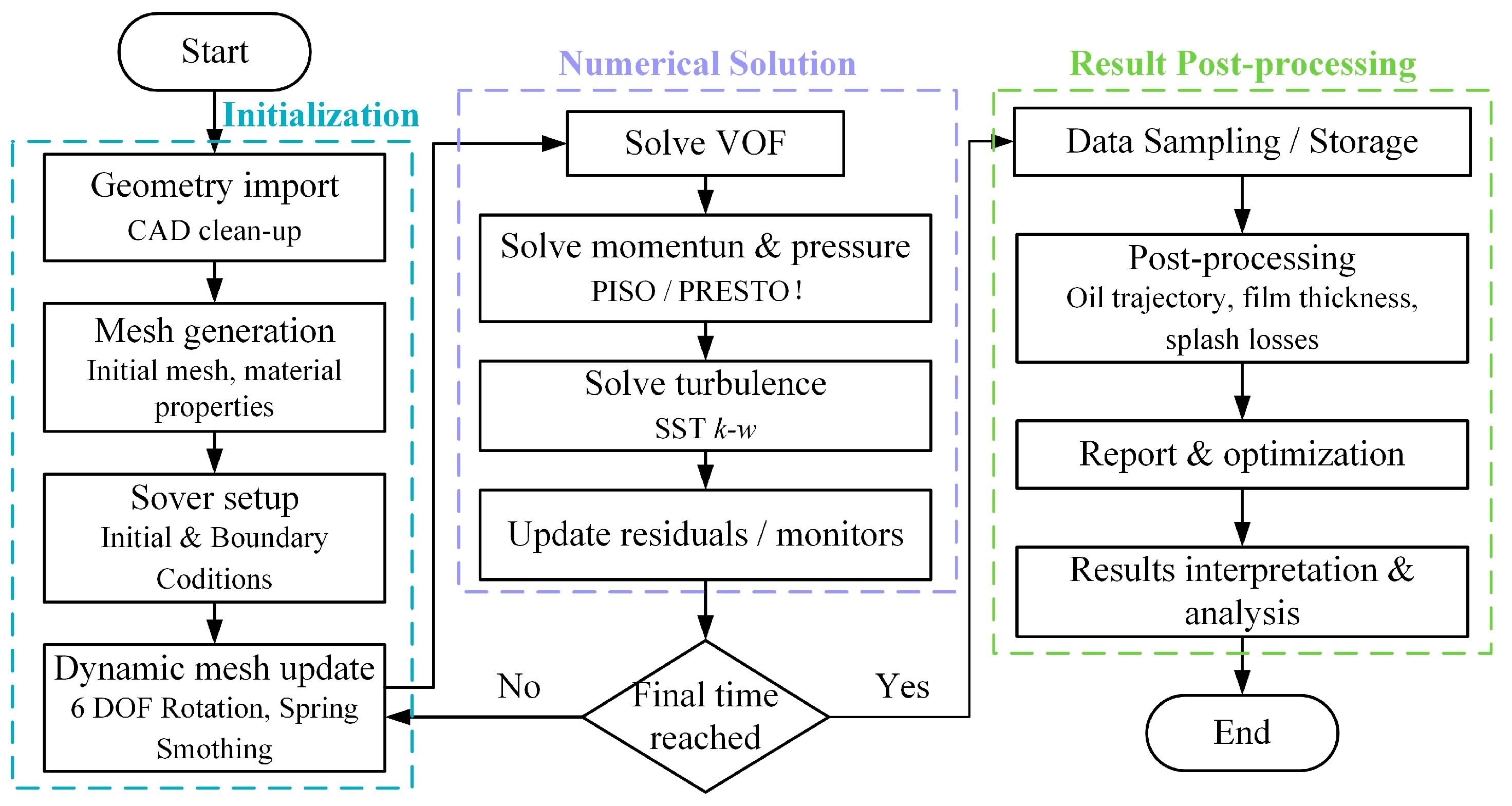
Figure 1. Solution strategy for the fuel injection gearbox.
Processes 13 02540 g001
Figure 2. Gearbox geometric dimensions.
Processes 13 02540 g002
Figure 3. Gearbox mesh model.
Processes 13 02540 g003
Figure 4. Independence and accuracy verification. (a) Grid independence verification. (b) Comparison of numerical results and experimental verification.
Processes 13 02540 g004
Figure 5. Distribution of oil volume in the gear meshing area at different speeds.
Processes 13 02540 g005
Figure 6. Distribution of oil volume in the gear surface area at different speeds.
Processes 13 02540 g006
Figure 7. Oil-phase volume fraction at point P versus time for each jet speed.
Processes 13 02540 g007
Figure 8. Distribution of oil eddy viscosity in the gear meshing area at different speeds.
Processes 13 02540 g008
Figure 9. Eddy viscosity at point P at different speeds.
Processes 13 02540 g009
Figure 10. Turbulent kinetic energy distribution in the mesh region at different speeds. (a) 20 m/s. (b) 30 m/s. (c) 40 m/s. (d) 50 m/s.
Processes 13 02540 g010
Figure 11. Turbulent kinetic energy distributions at point P at different speeds.
Processes 13 02540 g011
Figure 12. Distribution of oil velocity in the gear meshing area.
Processes 13 02540 g012
Figure 13. Distribution of oil velocity in the gear meshing area at different speeds.
Processes 13 02540 g013
Figure 14. Velocity evolution at monitoring point P at different speeds.
Processes 13 02540 g014
Figure 15. Streamline patterns at different speeds. (a) 20 m/s. (b) 30 m/s.
Processes 13 02540 g015
Disclaimer/Publisher’s Note: The statements, opinions and data contained in all publications are solely those of the individual author(s) and contributor(s) and not of MDPI and/or the editor(s). MDPI and/or the editor(s) disclaim responsibility for any injury to people or property resulting from any ideas, methods, instructions or products referred to in the content.