

Investigation of a Composite Material Painting Method: Assessment of the Mixture Curing of Organic Coatings


Abstract
1. Introduction
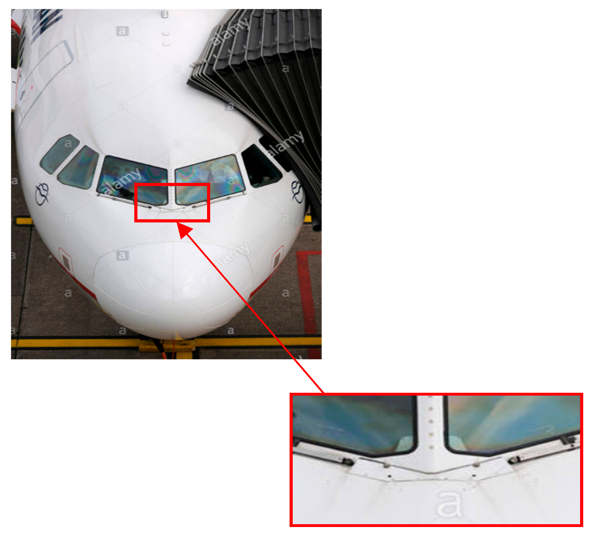
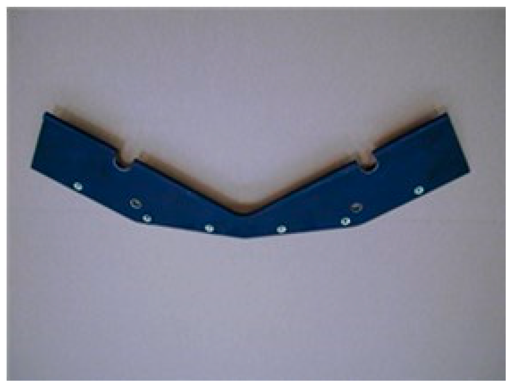
- Porosity: A common feature of the Kevlar composites, porosity can be challenging to remove and has an impact on the final surface finish [1].
- Surface condition: The presence of reinforcement fibers, such as Kevlar, may result in an uneven surface that affects the paint’s adhesion and appearance [1].
- Adhesive quality: For longevity and functionality, it is essential that the paint layers and the Kevlar composite adhere strongly [1].
- High tensile strength: Kevlar has five times the weight-to-tear strength ratio of steel.
- Light weight: It is very lightweight, making it ideal for applications where weight is important.
- High temperature resistance: Kevlar can withstand temperatures up to 360 °C without losing its mechanical properties.
- Chemical resistance: It is resistant to many chemicals, such as acids and other corrosive substances.
- Personal protective equipment: Kevlar is used in the production of bulletproof vests, helmets, gloves, and protective footwear.
- Aeronautics: Kevlar is used in the construction of airplanes and helicopters to reduce weight and increase safety.
- Shipbuilding: It is used to produce anchor cables and ropes.
- Sports: Kevlar is used in the production of sports equipment, such as tennis rackets or diving equipment, to increase endurance and reduce weight.
- Construction: Kevlar is used to increase the earthquake resistance of building and bridge structures.
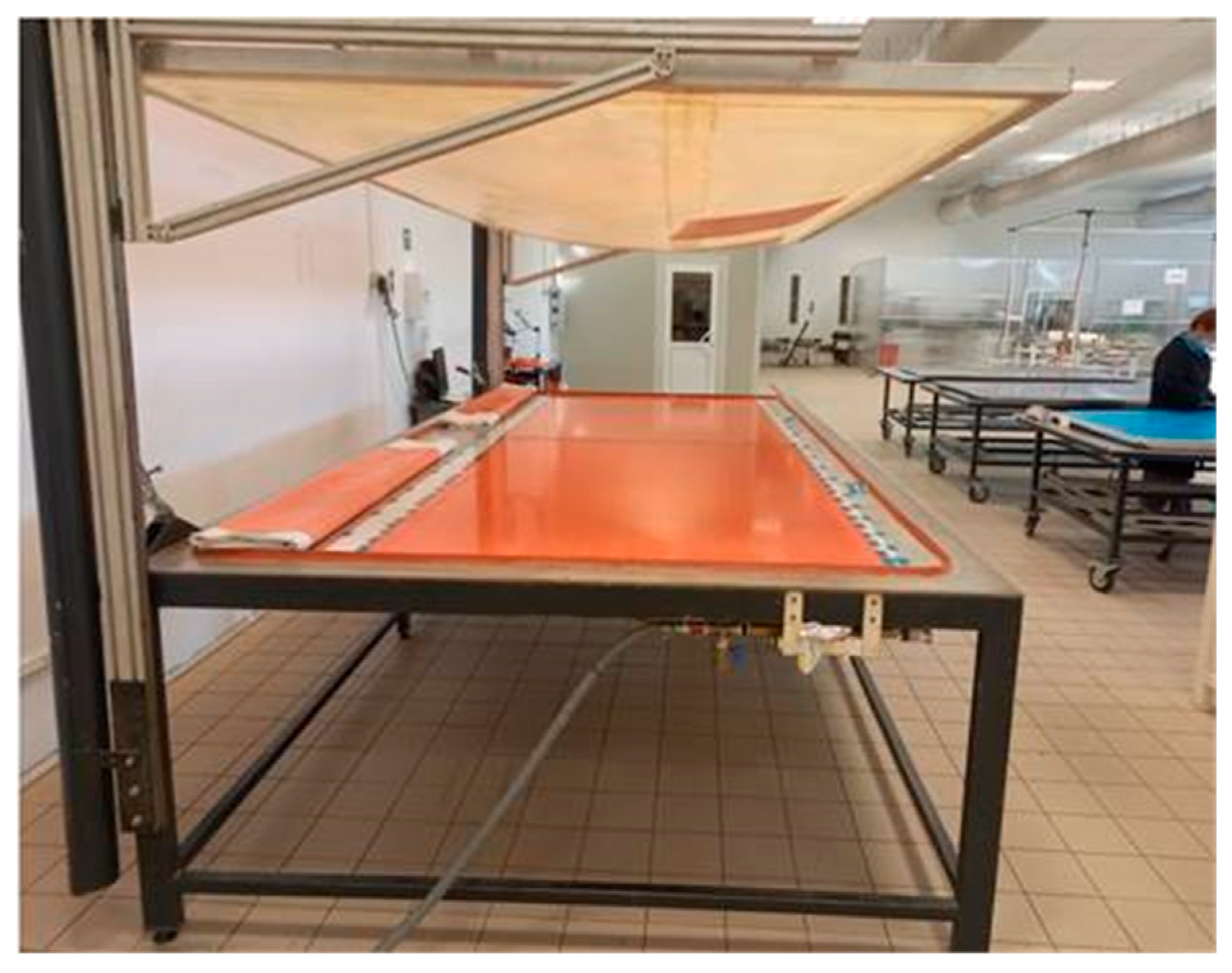
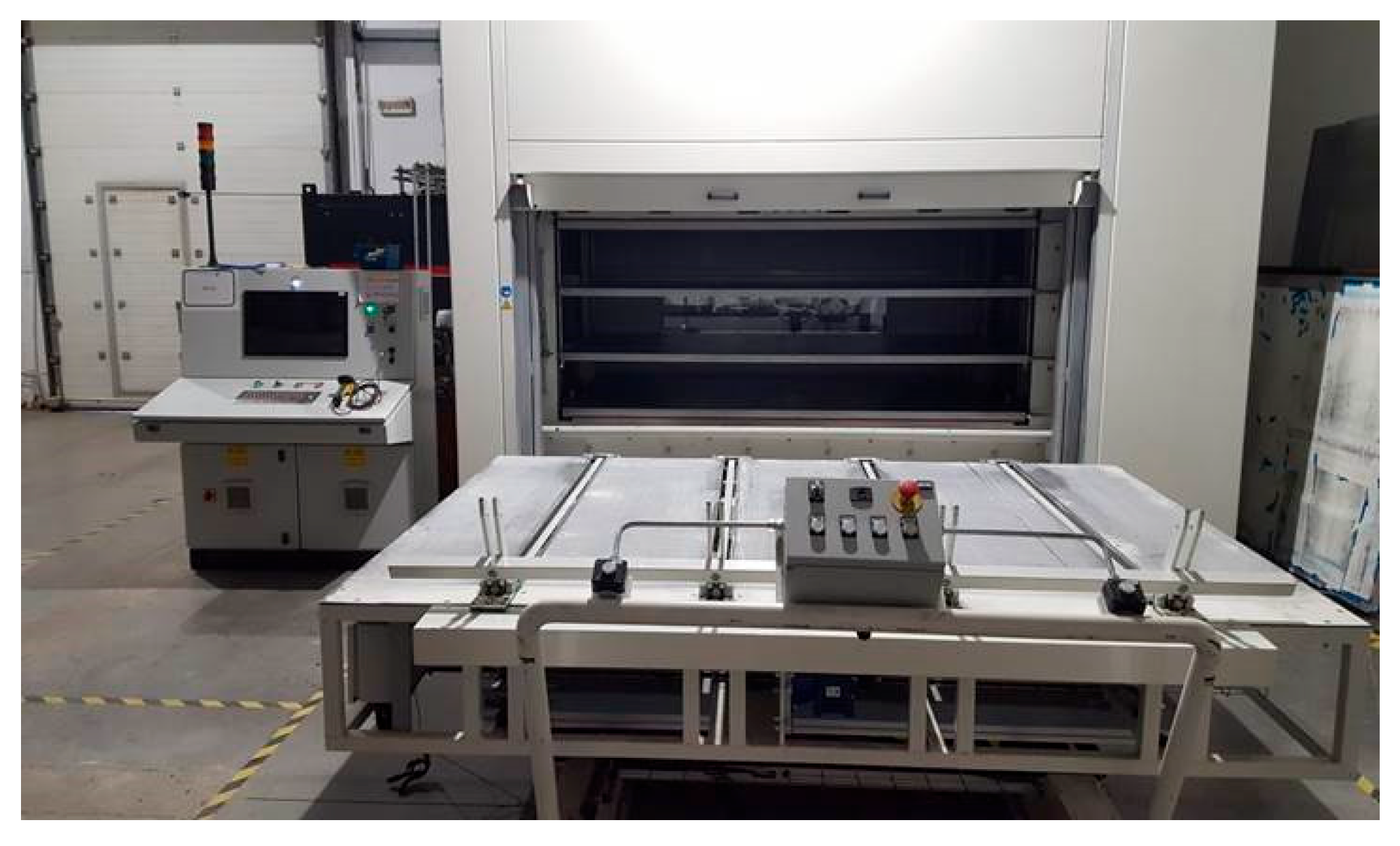
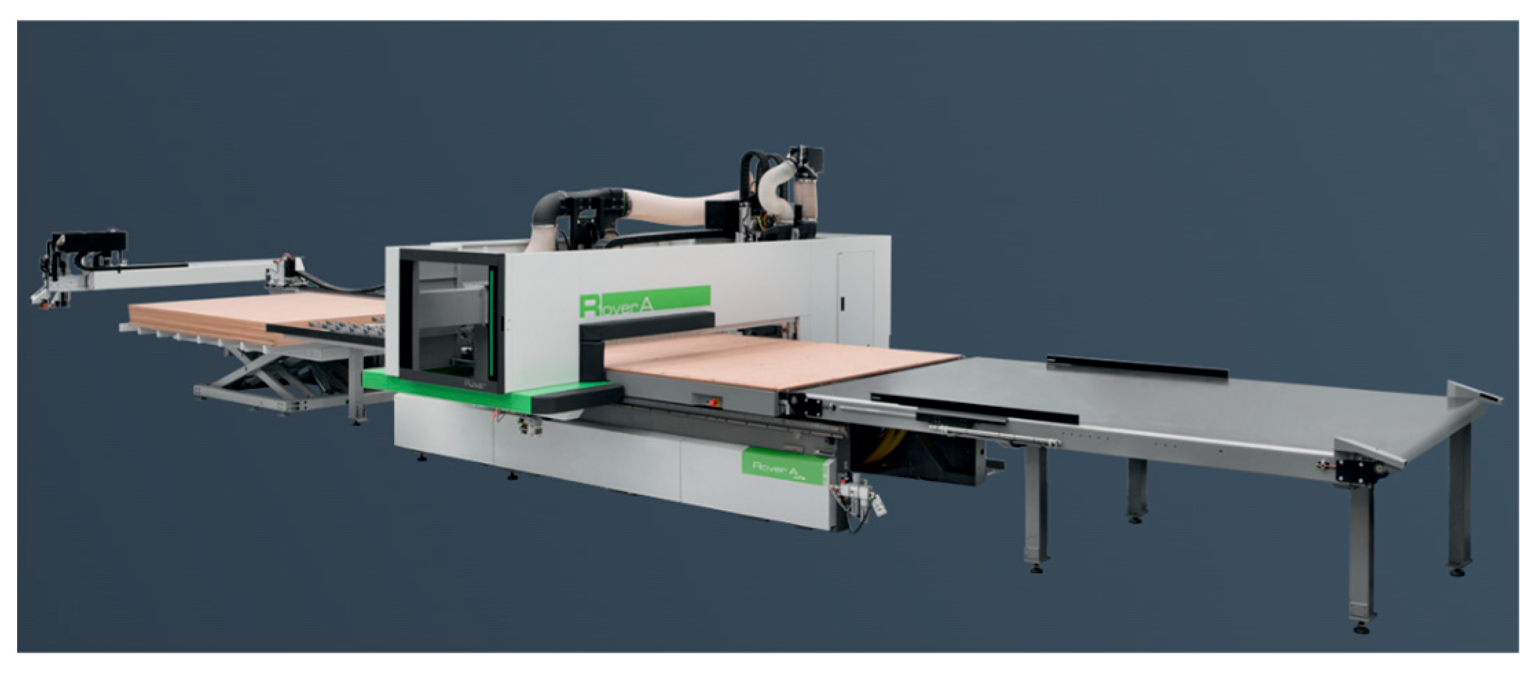
2. Method for Validating the Complete Curing of Organic Coatings
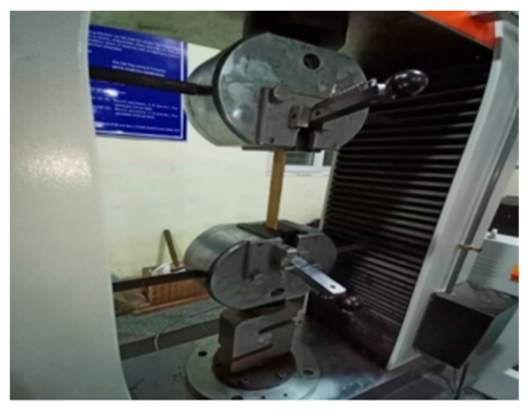
- Tensile tests: These tests measure Kevlar’s ability to withstand tensile forces and stretch without breaking. These tests are typically performed by tensing a sample of Kevlar material into a test fixture and measuring the force required to break the material (Figure 2).
- 2.
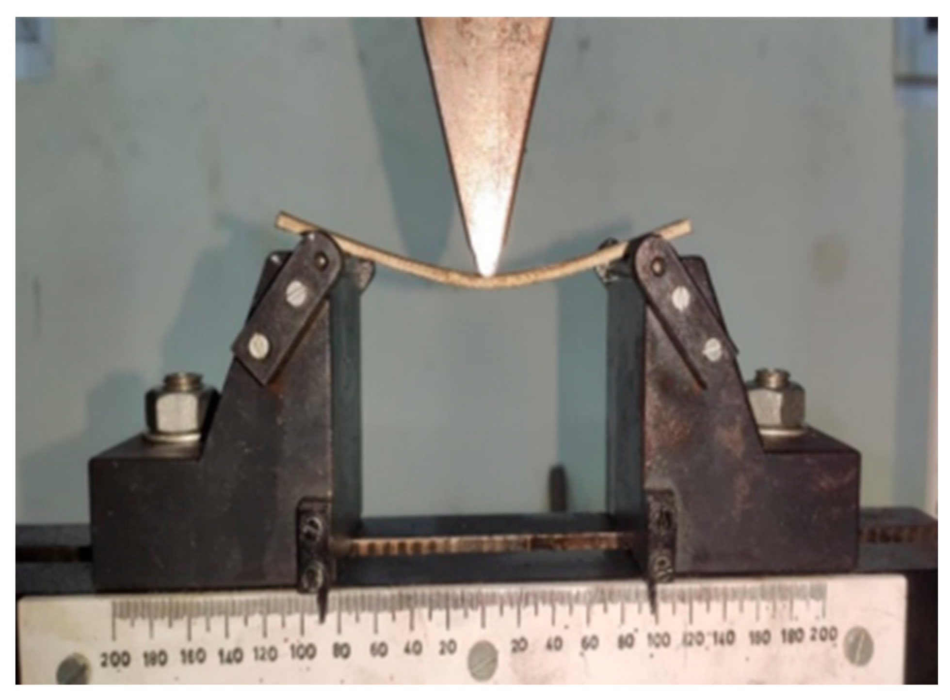
- Compression tests: These tests measure Kevlar’s ability to withstand compressive forces and maintain its shape. These tests are typically performed by compressing a sample of Kevlar material into a test device and measuring the force required to compress the material (Figure 3).
- 3.
- Fire tests: These tests measure Kevlar’s ability to withstand high temperatures and prevent flames from spreading. These tests are typically performed by exposing a sample of Kevlar material to a flame and measuring the time it takes for the flame to propagate.
- 4.
- Corrosion tests: These tests measure Kevlar’s ability to resist corrosion caused by chemicals and moisture. These tests are typically performed by exposing a sample of Kevlar material to chemicals or wet environments and measuring the changes in weight and physical properties.
- 5.
- Impact resistance tests: These tests measure Kevlar’s ability to withstand impact with other objects. These tests are usually performed by hitting a sample of Kevlar material with an object and measuring the level of damage.
- Failure to comply with the drying time specified in the material data sheet.Drying temperature lower than that specified in the material data sheet.
- The presence of moisture above the limits specified in the material data sheet in the storage, preparation, or application area.
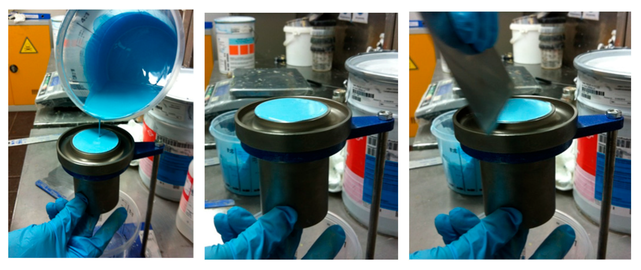
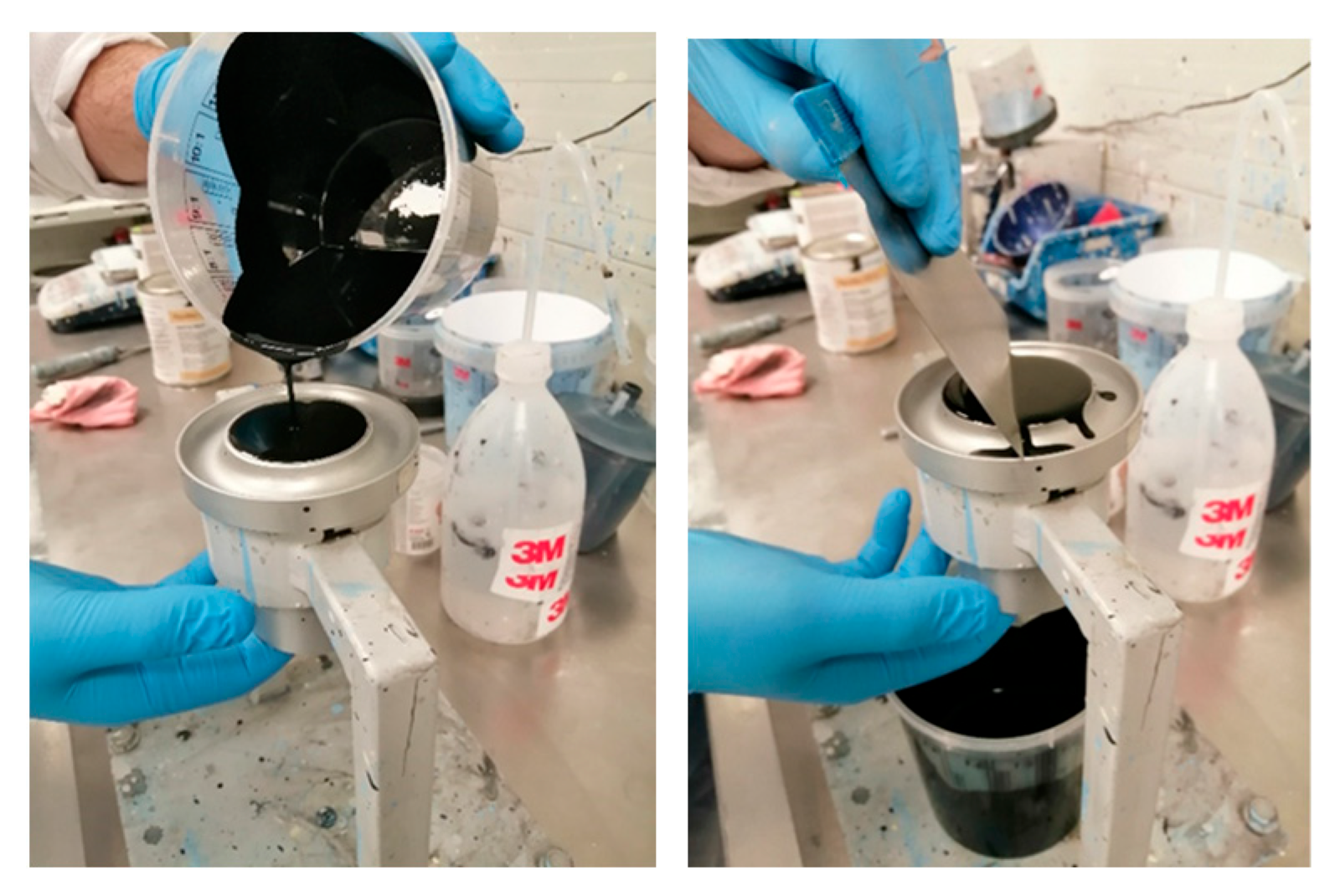
- Failure to comply with the volumetric or mass ratio when preparing the mixture.
- The presence of water vapor on hoses or paint guns.
- Non-compliant chemical commotion of raw materials.
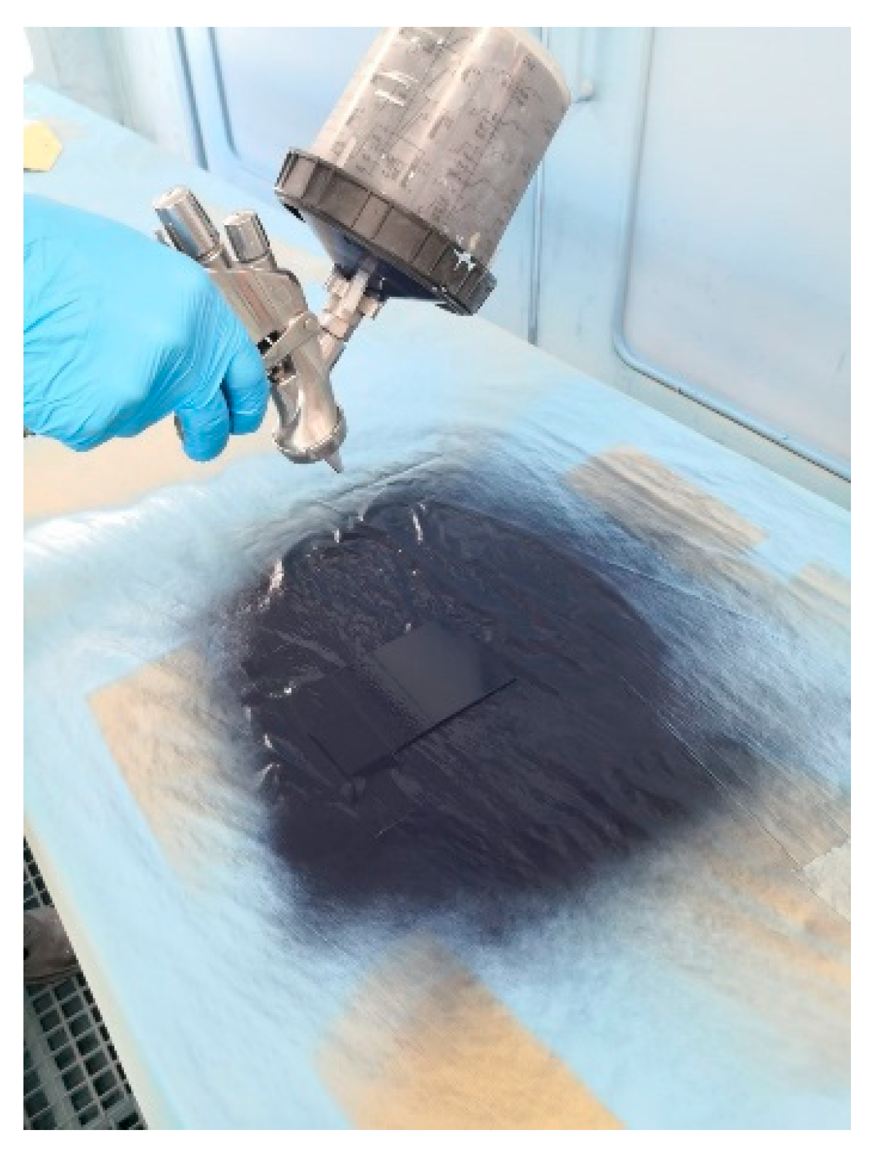
- Non-compliant applied layer thickness.
- 28 s for 50 passes
- 24 s for 50 passes
- 32 s for 50 passes
- In the case of series production, testing is performed on a minimum of three pieces from the batch. In the case of test tubes, it is mandatory that this test be carried out on each individual test tube before any other paint validation test is carried out.
- The solvent agent used: recommended Methyl-Ethyl-Ketone (MEC)
- Type of coating, reference, or name of the substance/paint.
- Description of the curing cycle, ambient drying time, or steaming time.
- Test results
- Any pertinent comments related to the result, the way of testing, or other details that could influence the result
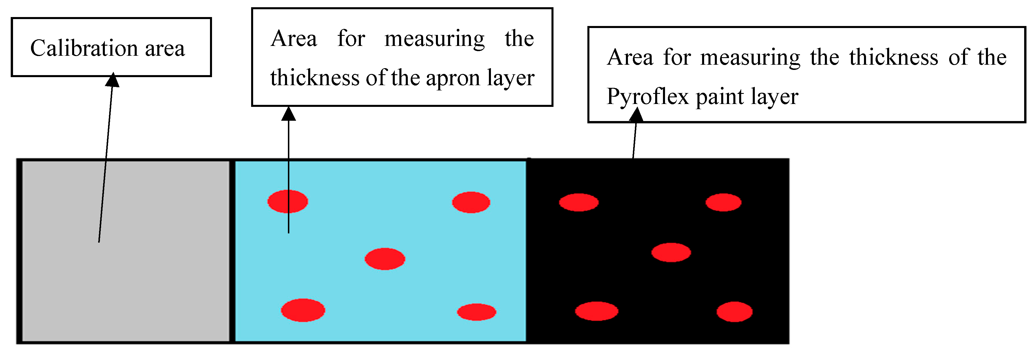
2.1. Measurement of Paint Layer Thickness, According to EN ISO 2808:2019 [11]
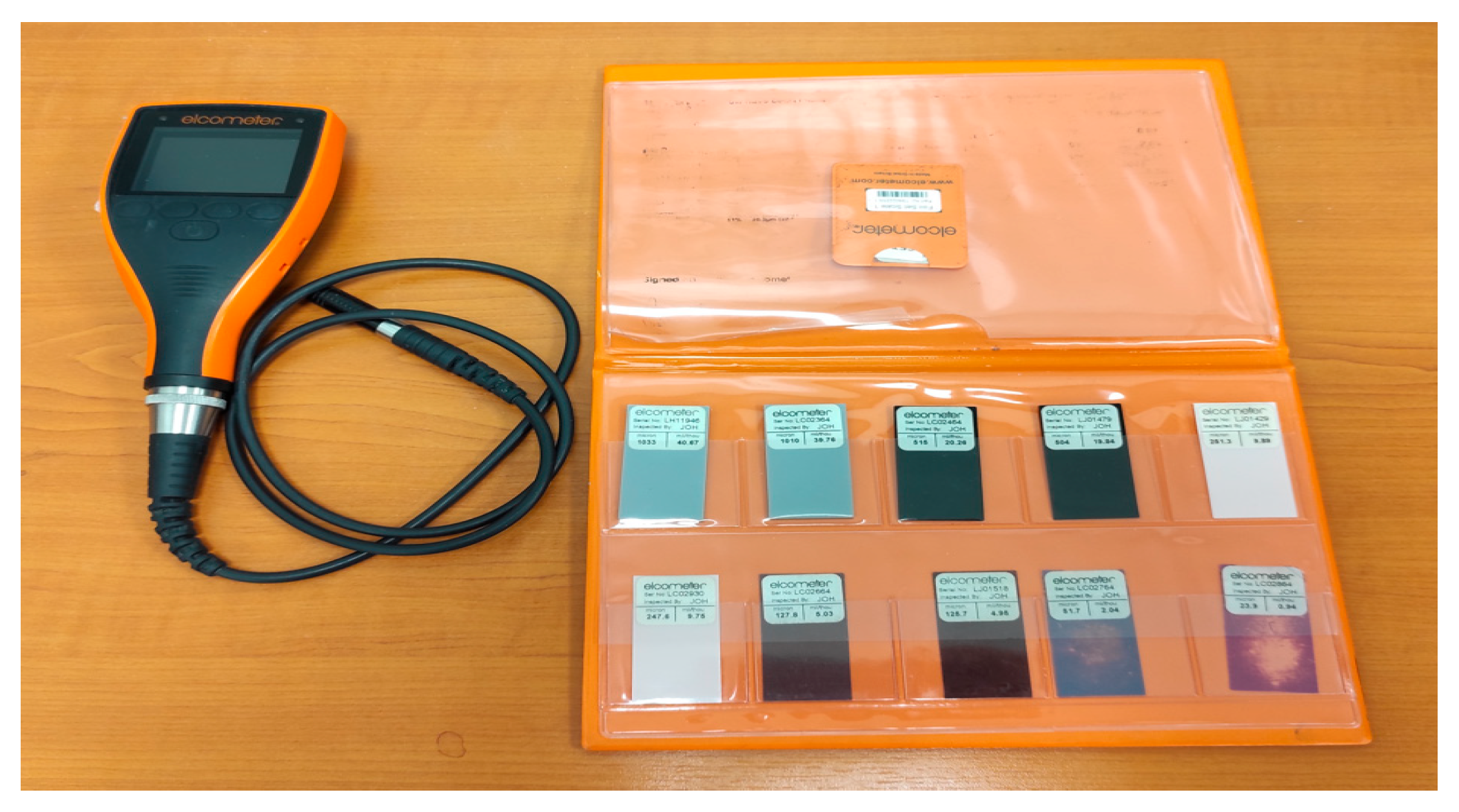
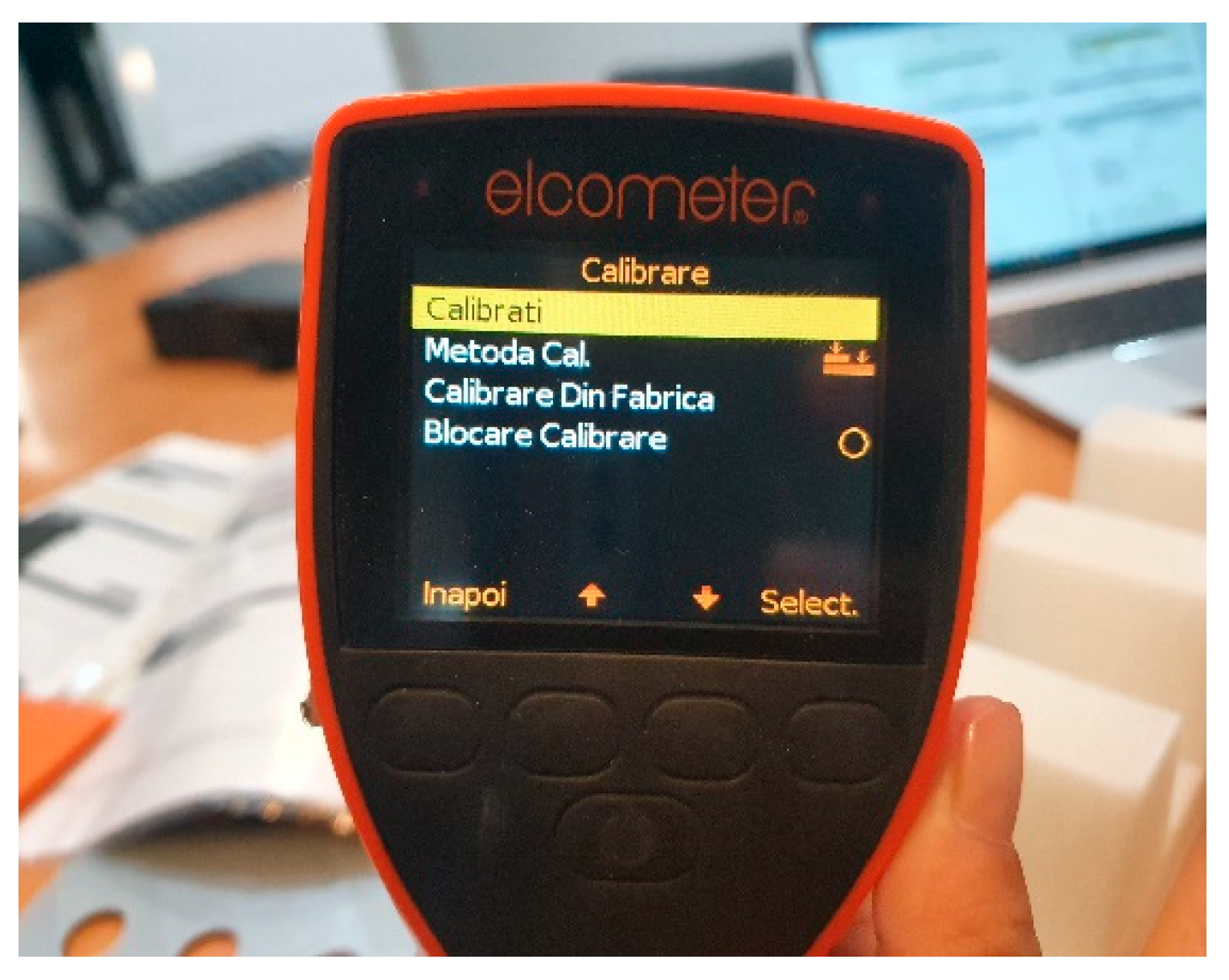
2.2. Measurement of the Thickness of the Coating Using Magnetic Currents
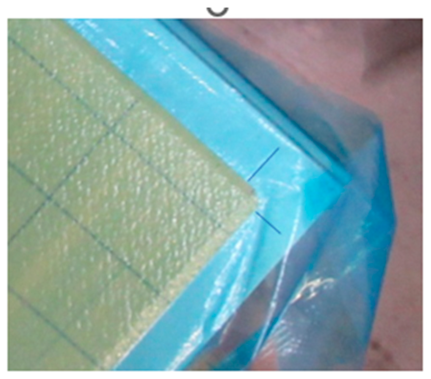
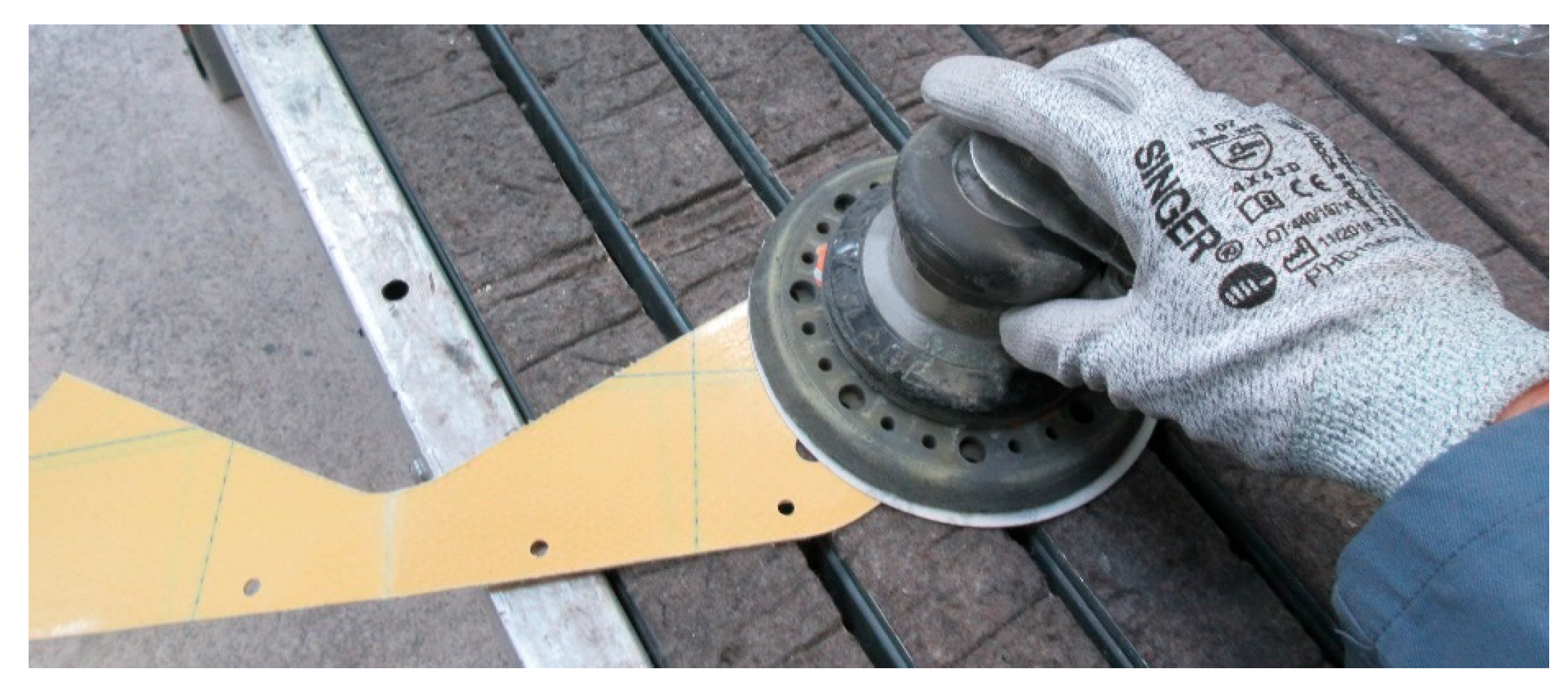
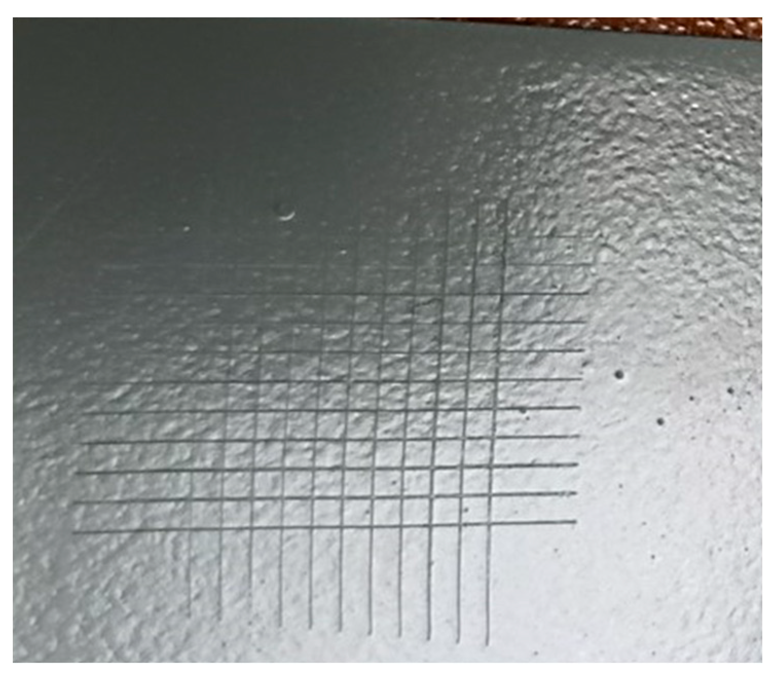
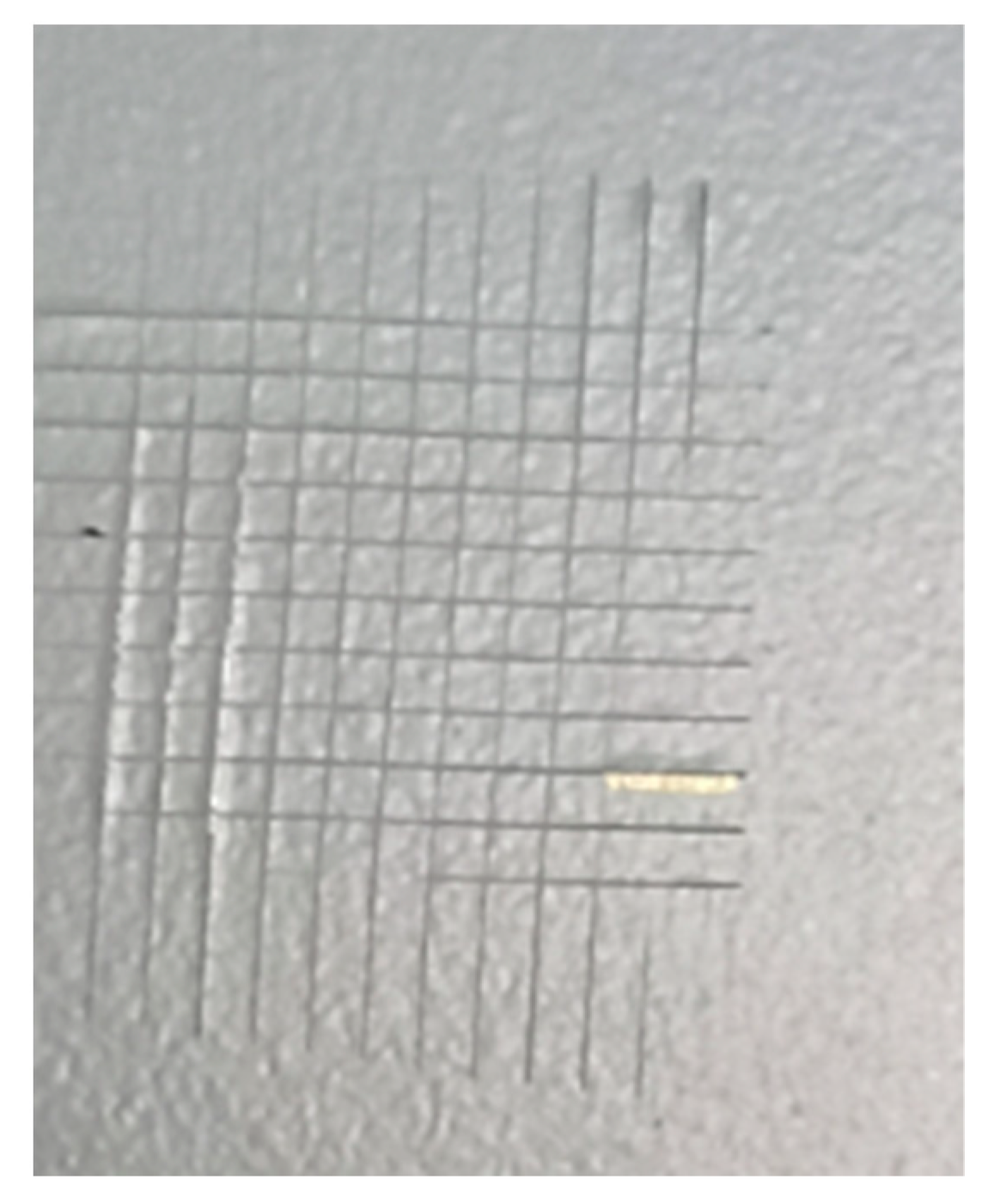
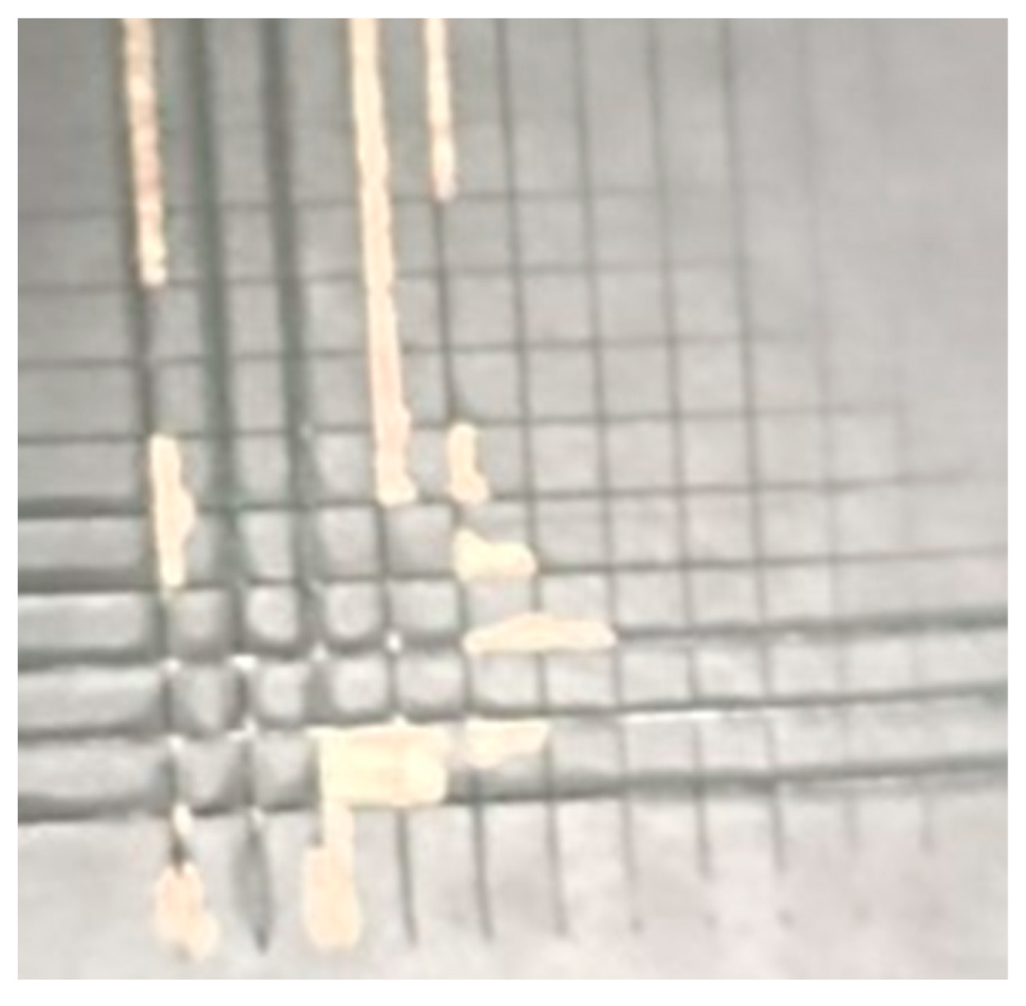
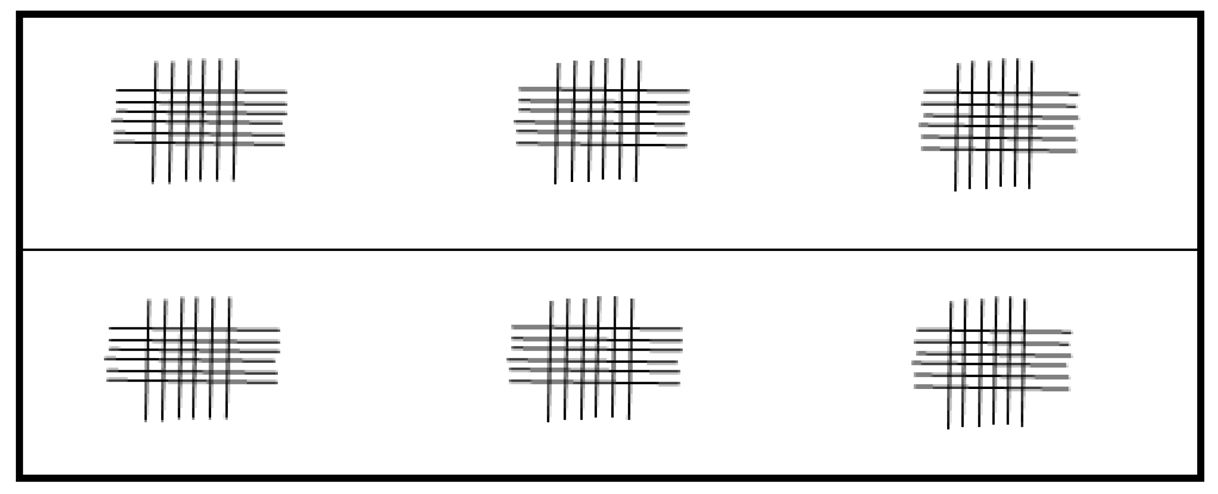
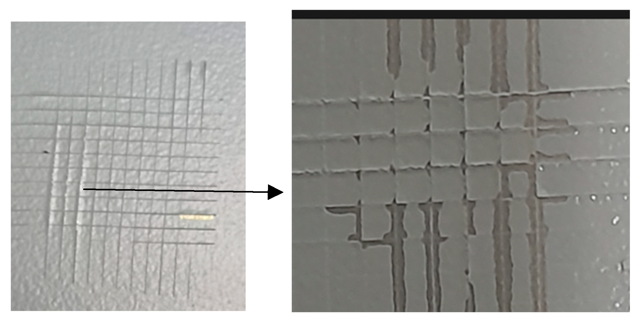
- A sharp blade is used to cut a grid through the coating, producing tiny squares.
- Although the incisions should pass through the coating, the Kevlar substrate should not sustain significant damage.
- The sliced area is covered with regular adhesive tape, which is then swiftly removed.
- The quantity of coating that separates with the tape is examined.
- Single-blade hand cutting tool.
- Single-blade cutting tool fixed in a motorized device.
- Cutter with rigid blade and “V”-shaped blade. In this situation, the thickness of the blade is not specified, as long as the condition that the cut is in the shape of a “V” over the entire thickness of the layer is observed.
- Multi-blade hand-cutting tool.
- Multi-blade cutting tool clamped in a motorized device
- Light brushing with a soft brush along each diagonal of the frame.
- Pressure-sensitive adhesive tape.
- Compressed air or nitrogen.
- Temperature and humidity during the test
- Type of cutting tool used and working mode
- The method used to remove peeling paint off
- Test result
- Any deviation from the way of working
- Any abnormal features observed during the test
- Test date
3. Determination of Liquid Resistance: Water Immersion Method, According to ISO 2812-2:2018
- A tank of the right size, equipped with a heating system and thermostat
- Water recirculation system
- Specimen holder, allowing specimens to be placed at an angle between 0° and 20° in vertical input with a minimum spacing of 30 mm between specimens and from the tank’s edge or bottom.
- Class 0 before immersion
- Class 1 maximum after immersion
4. Discussion
5. Conclusions
Author Contributions
Funding
Data Availability Statement
Conflicts of Interest
References
- Skelskey, T.J.; Daniels, M.E. Surface appearance categorization of sheet molded composites. In Proceedings of the Composites and Advanced Materials Expo, CAMX 2021, Dallas, TX, USA, 19–21 October 2021; pp. 244–258. [Google Scholar]
- Singha, T.J.; Samantab, S. Characterization of Kevlar Fiber and Its Composites: A Review. Mater. Today Proc. 2015, 2, 1381–1387. [Google Scholar] [CrossRef]
- Goud, B.N.; Sura, S.; Aravind, P.; Lal, B.J.; Sanskruti, K.; Pavan, C. An experimental study on mechanical properties of Kevlar composite for aircraft structural applications. Mater. Today Proc. 2022, 64, 909–916. [Google Scholar] [CrossRef]
- Linul, P.; Bănică, R.; Grad, O.; Linul, E.; Vaszilcsin, N. Highly Electroconductive Metal-Polymer Hybrid Foams Based on Silver Nanowires: Manufacturing and Characterization. Polymers 2024, 16, 608. [Google Scholar] [CrossRef] [PubMed]
- Mouritz, A.P. Manufacturing of fibre–polymer composite materials. In Introduction to Aerospace Materials; Woodhead Publishing: Sawston, UK; Cambridge, UK, 2012; Volume 10, pp. 303–337. [Google Scholar]
- Jamir, M.R.M.; Majid, M.S.A.; Khasri, A. Natural lightweight hybrid composites for aircraft structural applications. In Sustainable Composites for Aerospace Applications; Woodhead Publishing: Sawston, UK; Cambridge, UK, 2018; pp. 155–170. [Google Scholar]
- Balea, A.; Fuente, E.; Blanco, A.; Negro, C. Nanocelluloses: Natural-based materials for fiber-reinforced cement composites. A critical review. Polymers 2019, 11, 518. [Google Scholar] [CrossRef] [PubMed]
- Balakrishnan, P.; John, M.J.; Pothen, L.; Sreekala, M.S.; Thomas, S. Natural fibre and polymer matrix composites and their applications in aerospace engineering. In Advanced Composite Materials for Aerospace Engineering; Woodhead Publishing: Sawston, UK; Cambridge, UK, 2016; pp. 365–383. [Google Scholar]
- Sherif, G.; Chukov, D.; Tcherdyntsev, V.; Torokhov, V. Effect of formation route on the mechanical properties of the polyethersulfone composites reinforced with glass fibers. Polymers 2019, 11, 1364. [Google Scholar] [CrossRef] [PubMed]
- Barile, C.; Casavola, C. Mechanical characterization of carbon fiber-reinforced plastic specimens for aerospace applications. In Mechanical and Physical Testing of Biocomposites, Fibre-Reinforced Composites and Hybrid Composites; Woodhead Publishing: Sawston, UK; Cambridge, UK, 2019; pp. 387–407. [Google Scholar]
- EN ISO 2808:2019; Paints and varnishes—Determination of film thickness. ISO: Geneva, Switzerland, 2019.
- Mera, H.; Takata, T. High-Performance Fibers. In Ullmann’s Encyclopedia of Industrial Chemistry; Wiley: Hoboken, NJ, USA, 2000. [Google Scholar]
- NF EN ISO 2808:2018; Peintures et Vernis—Détermination de L’épaisseur du Feuil. ISO: Geneva, Switzerland, 2018.
- NF EN ISO 2409:2020; Peintures et Vernis—Essai de Quadrillage. ISO: Geneva, Switzerland, 2020.
- Linul, E.; Marşavina, L. Prediction of fracture toughness for open cell polyurethane foams by finite-element micromechanical analysis. Iran. Polym. J. 2011, 20, 735–746. [Google Scholar]
- Yu, K.; He, T. Silver-Nanowire-Based Elastic Conductors: Preparation Processes and Substrate Adhesion. Polymers 2023, 15, 1545. [Google Scholar] [CrossRef] [PubMed]
- Wang, J.; Yu, J.; Bai, D.; Li, Z.; Liu, H.; Li, Y.; Chen, S.; Cheng, J.; Li, L. Biodegradable, Flexible, and Transparent Conducting Silver Nanowires/Polylactide Film with High Performance for Optoelectronic Devices. Polymers 2020, 12, 604. [Google Scholar] [CrossRef] [PubMed]
- ISO2178:2016; Non-magnetic coatings on magnetic substrates—Measurement of coating thickness—Magnetic method, Published (Edition 3, 2016). ISO: Geneva, Switzerland, 2016.
- Madkour, T.M.; Abdelazeem, E.A.; Tayel, A.; Mustafa, G.; Siam, R. In situ polymerization of polyurethane-silver nanocomposite foams with intact thermal stability, improved mechanical performance, and induced antimicrobial properties. J. Appl. Polym. Sci. 2016, 133, 43125. [Google Scholar] [CrossRef]
- Pahlevanneshan, Z.; Deypour, M.; Kefayat, A.; Rafienia, M.; Sajkiewicz, P.; Esmaeely Neisiany, R.; Enayati, M.S. Polyurethane-Nanolignin Composite Foam Coated with Propolis as a Platform for Wound Dressing: Synthesis and Characterization. Polymers 2021, 13, 3191. [Google Scholar] [CrossRef]
- ISO 16276-2:2025; Corrosion protection of steel structures by protective paint systems—Assessment of, and acceptance criteria for, the adhesion/cohesion (fracture strength) of a coatingPart 2: Cross-cut testing and X-cut testing. ISO: Geneva, Switzerland, 2025.
- Available online: https://aerospace.akzonobel.com/en/products/pyroflex-7d713 (accessed on 10 May 2025).
- Arockiam, N.J.; Jawaid, M.; Saba, N. Sustainable bio composites for aircraft components. In Sustainable Composites for Aerospace Applications; Woodhead Publishing: Sawston, UK; Cambridge, UK, 2018; pp. 109–123. [Google Scholar]
- Alonso-Martin, P.P.; Gonzalez-Garcia, A.; Lapena-Rey, N.; Fita-Bravo, S.; Martinez-Sanz, V.; Marti-Ferrer, F. Green Aircraft Interior Panels and Method of Fabrication. European Patent EP2463083A2, 13 June 2012. [Google Scholar]
- NF EN ISO 2812-2:2018; Peintures et Vernis—Détermination de la Résistance aux Liquides—Partie 2: Méthode par Immersion Dans L’eau. ISO: Geneva, Switzerland, 2018.
- EN NF 9100:2018; Quality Management Systems–Requirements for Aviation, Space and Defence Organisation. BSI: London, UK, 2018.
- AITM1_0024_issue 3_2020, Airbus Test Method Determination of the Completeness of Cure of Organic Coatings. Available online: https://www.en-standard.eu/?gad_source=1&gad_campaignid=22489671069&gclid=Cj0KCQjws4fEBhD-ARIsACC3d29UEAubqEfN3eF40kQixAgELtwH7Z4rBIEVEFeApr1_TQn2OmgAhkEaAjhIEALw_wcB (accessed on 22 July 2025).
- Nioata, A.; Țăpirdea, A.; Chivu, O.R.; Feier, A.; Enache, I.C.; Gheorghe, M.; Borda, C. Workplace Safety in Industry 4.0 and Beyond: A Case Study on Risk Reduction Through Smart Manufacturing Systems in the Automotive Sector. Safety 2025, 11, 50. [Google Scholar] [CrossRef]
- Rajak, D.K.; Pagar, D.D.; Menezes, P.L.; Linul, E. Fiber-Reinforced Polymer Composites: Manufacturing, Properties, and Applications. Polymers 2019, 11, 1667. [Google Scholar] [CrossRef] [PubMed]
- Azimi, B.; Nourpanah, P.; Rabiee, M.; Arbab, S. Poly (lactide-co-glycolide) Fiber: An Overview. J. Eng. Fiber Fabr. 2014, 9, 155892501400900. [Google Scholar] [CrossRef]
- Rînjea, C.; Chivu, O.R.; Darabont, D.-C.; Feier, A.I.; Borda, C.; Gheorghe, M.; Nitoi, D.F. Influence of the Thermal Environment on Occupational Health and Safety in Automotive Industry: A Case Study. Int. J. Environ. Res. Public Health 2022, 19, 8572. [Google Scholar] [CrossRef] [PubMed]


| Nr.crt. | Material Resource | Resource Type |
|---|---|---|
| 1 | Aluminium test tube | Raw materials |
| 2 | Apret 5014 PU Base Blue | Raw materials |
| 3 | Apret 5014 PU Blue-Hardener | Raw materials |
| 4 | Pyroflex Paint 7D713 Black-Base | Raw materials |
| 5 | Pyroflex 7D713 Black-Hardening Paint | Raw materials |
| 6 | Thinner 0651 | Raw materials |
| 7 | Paper Scotch tape | Consumables |
| 8 | Paint filter, 190 μm | Consumables |
| 9 | Lavete antistatic | Consumables |
| 10 | Alcool izopropilic | Consumables |
| 11 | Volumetric mixing vessel | Tools |
| 12 | Mixing ruler | Tools |
| 13 | ISO 4 viscosity cup | Tools |
| 14 | Timer | Tools |
| 15 | Paint Gun WS400 | Equipment |
| 16 | Scale | Tools |
| 17 | Temperature- and humidity-controlled Paint preparation area | Facilities |
| 18 | Paint booth | Facilities |
| 19 | Sandpaper P500 | Consumables |
| Crt. No. | Operation | Timed Time (s) |
|---|---|---|
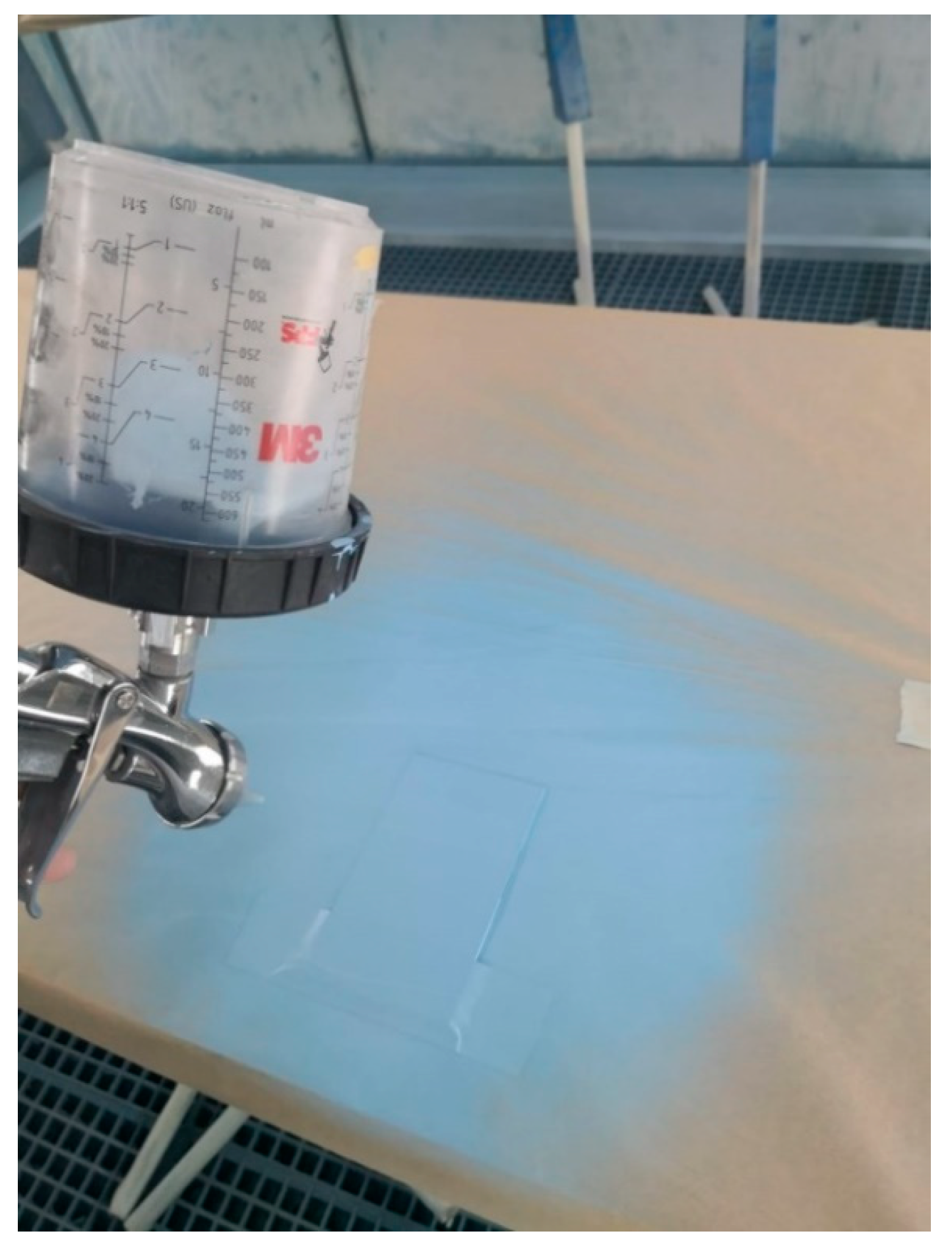
| 1 | Masking with Scotch tape, 1 cm | 120 |
| 2 | Preparation of Apret mixture | 600 |
| 3 | Viscosity measurement | 480 |
| 4 | Filter apron mixture | 480 |
| 5 | Application of apron mixture | 180 |
| 6 | Prepared stew | 3600 |
| 7 | Masking with Scotch tape 2/3 of the surface | 180 |
| 8 | Reactivate apron | 300 |
| 9 | Preparation of paint mixture | 600 |
| 10 | Paint viscosity measurement | 480 |
| 11 | Paint mixture filtration | 480 |
| 12 | Paint application | 180 |
| 13 | Paint steaming | 3600 |
| 14 | Specimen unmasking | 120 |
| Timp total de lucru = 12,480 s | ||
| 60 μm | 61–120 μm | 121–250 μm | |
|---|---|---|---|
| Soft material test tube | 2 mm | 2 mm | 3 mm |
| Hard material test tube | 1 mm | 2 mm | 3 mm |
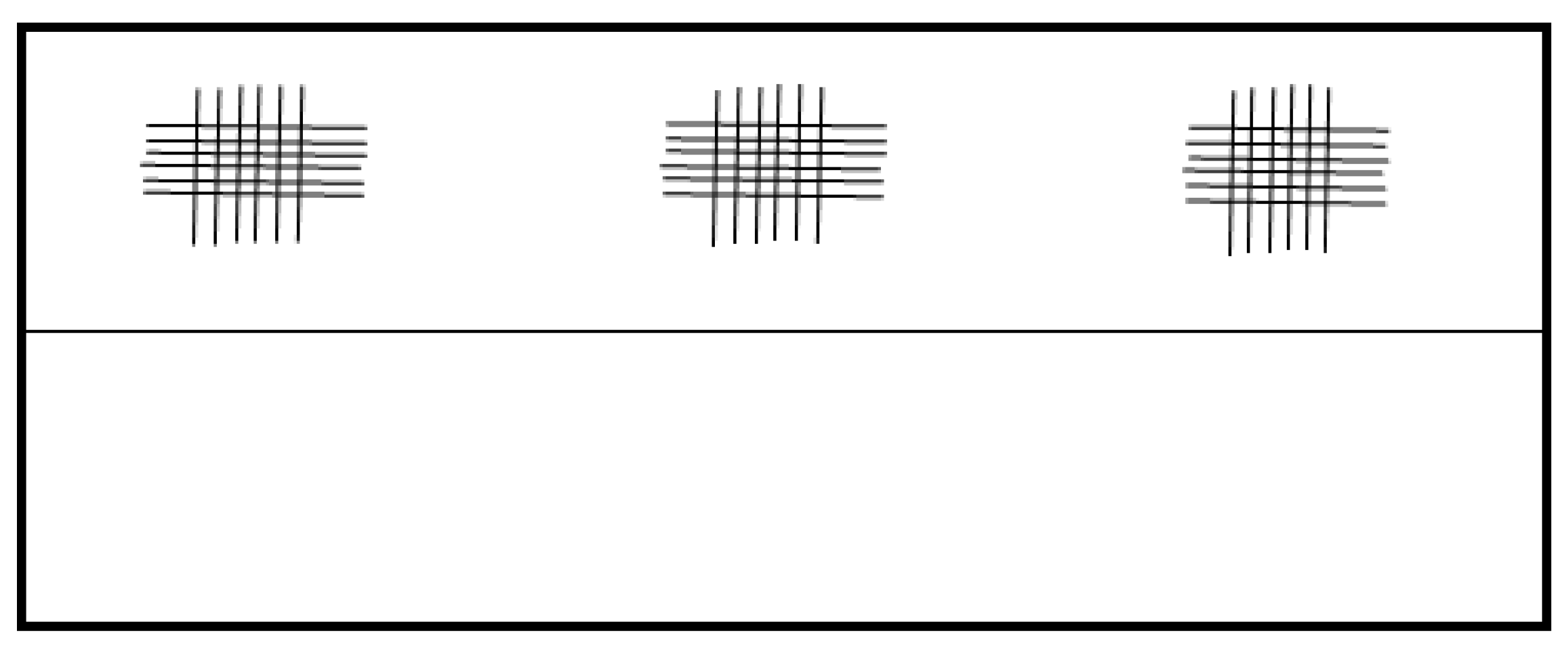
| Classification | Description | Framing Layout |
|---|---|---|
| 0 | The edges of the incisions are perfectly smooth. The paint did not come off. |  |
| 1 | Detachment of small pieces at the intersection of the incisions. Less than 5% of the squared area is affected. |  |
| 2 | The paint peels off along the lines and/or at the intersection of the incisions. Between 5% and 15% of the tiled area is affected. |  |
| 3 | The paint peels off along with the incisions in large pieces, and/or certain squares are partially or totally detached. Between 15% and 35% of the checkered area is affected. |  |
| 4 | The paint peels off along with the incisions in large pieces, and/or certain squares are partially or totally detached. Between 35% and 65% of the tiled area is affected. |  |
| 5 | All large detachments that cannot be classified in class 4. |
| Apret Report and Mixture | |||
|---|---|---|---|
| Product Name | Reference | Volume Ratio | Mass Ratio |
| Baza Apret 5425/6407 | MP00846 | 2 | 100 g (±6 g) |
| Hardener Apret 0707/9000 | MP00848 | 1 | 32 g (±1 g) |
| Diluent 0491/9000 | MP00050 | 1 | 20 g (0/+5 g) |
| Ratio and Mixture Pyroflex 7D13 Black | |||
|---|---|---|---|
| Product Name | Reference | Volume Ratio | Mass Ratio |
| Base Pyroflex 7D13 Black | MP01647-AA | 3 | 100 g (±6 g) |
| Hardner pyroflex 0651 | MP01648-AA | 1 | 32 g (±1 g) |
| Thinner C25/90S | MP00363-AA | 1 | 32 g (0/+10 g) |
Disclaimer/Publisher’s Note: The statements, opinions and data contained in all publications are solely those of the individual author(s) and contributor(s) and not of MDPI and/or the editor(s). MDPI and/or the editor(s) disclaim responsibility for any injury to people or property resulting from any ideas, methods, instructions or products referred to in the content. |
© 2025 by the authors. Licensee MDPI, Basel, Switzerland. This article is an open access article distributed under the terms and conditions of the Creative Commons Attribution (CC BY) license (https://creativecommons.org/licenses/by/4.0/).
Share and Cite
Barbu, A.; Feier, A.I.; Petzek, E.; Gheorghe, M. Investigation of a Composite Material Painting Method: Assessment of the Mixture Curing of Organic Coatings. Processes 2025, 13, 2394. https://doi.org/10.3390/pr13082394
Barbu A, Feier AI, Petzek E, Gheorghe M. Investigation of a Composite Material Painting Method: Assessment of the Mixture Curing of Organic Coatings. Processes. 2025; 13(8):2394. https://doi.org/10.3390/pr13082394
Chicago/Turabian StyleBarbu, Anca, Anamaria Ioana Feier, Edward Petzek, and Marilena Gheorghe. 2025. "Investigation of a Composite Material Painting Method: Assessment of the Mixture Curing of Organic Coatings" Processes 13, no. 8: 2394. https://doi.org/10.3390/pr13082394
APA StyleBarbu, A., Feier, A. I., Petzek, E., & Gheorghe, M. (2025). Investigation of a Composite Material Painting Method: Assessment of the Mixture Curing of Organic Coatings. Processes, 13(8), 2394. https://doi.org/10.3390/pr13082394