Article

Design and Development of a New 10 kV Overhead Line Fixing Device in Power System

1
School of Physics, Electronics and Intelligent Manufacturing, Huaihua University, Huaihua 418000, China
2
Key Laboratory of Intelligent Control Technology for Wuling-Mountain Ecological Agriculture in Hunan Province, Huaihua 418000, China
3
School of Fine Arts and Design, Huaihua University, Huaihua 418000, China
4
School of Chemistry and Materials Engineering, Huaihua University, Huaihua 418000, China
*
Author to whom correspondence should be addressed.
Processes 2025, 13(8), 2379; https://doi.org/10.3390/pr13082379
Submission received: 19 June 2025 / Revised: 16 July 2025 / Accepted: 22 July 2025 / Published: 26 July 2025
(This article belongs to the Section Energy Systems)

Abstract

In response to the problems of wire detachment, insulation layer damage, and low construction efficiency in the traditional hand tied wire fixing method for 10 kV overhead lines, this paper develops a new type of 10 kV overhead line fixing device. The device mainly consists of a buckle type base and an infinitely adjustable gripper. The base is quickly installed through mechanical interlocking buckles, supplemented by auxiliary buckles to enhance stability, and the edge arc design improves operational safety. The clamp is equipped with a raised diamond-shaped structure to increase the friction coefficient and meshing strength. Combined with an arc-shaped inner surface and an infinitely adjustable screw, it can adapt to insulated wires of different diameters. The fixed device has a simple structure, easy installation, and advantages such as firm fixation and adaptability to overhead lines of different diameters. The fixed device of the overhead power line has been subjected to finite element mechanical simulation and electronic universal testing machine tension and pressure testing, and can meet the on-site mechanical performance, effectively improving the construction efficiency and safety of the overhead power line in the distribution network.

1. Introduction

With the continuous growth of global electricity demand, 10 kV overhead lines, as the power transmission channels for urban and rural distribution networks as well as industrial parks, are leading to a continuous increase in power grid density. They face dual challenges posed by complex environments and the demand for high reliability. Additionally, severe environments such as typhoons and salt fog impose higher demands on the structural strength and adaptability of line fixation devices.
The existing fixed device structures commonly utilize various methods, such as clamp-style clamping, jumper insulation integration, combination opening and closing, and two-step locking. Zhang Guoqing and others in China developed a clamp-style clamping device that achieves wire fixation through mechanical hoop clamping, which boasts advantages such as simple structure, light weight, portability, and ease of quick installation. However, it has difficulty accommodating large wire diameters and may loosen or detach in strong wind conditions [1]. Zhao Liuheng has effectively eliminated the loosening and falling of the device by adding the fastening link of the insulating porcelain insulator, and the fixation effect is more reliable. Shi Mingming further developed a two-step locking device based on this, which enhances the anti-slip performance by using dual locking, ensuring the stability of the wire fixation. However, both devices lack the self-adaptive function of wire diameter, unable to adjust the wire diameter, and are difficult to meet the use requirements of wires with different wire diameters [2,3]. Scholars such as Luo Jin proposed the use of a combined opening and closing structure, which combines an insulator clamping structure and two wire fixing structures. Through modular design, it expands the application scenarios and can adapt to various installation needs. However, relying solely on round rods for fixation will reduce its reliability [4]. Wang Zhigang team designed the jumper insulation integrated device with an integrated design, which can effectively reduce the risk of wire damage and improve safety, but its complex structure limits the deployment of the device to double wishbone towers, and the manual installation cost is high [5]. Feng Yu team from abroad designed the clamping device, the device has strong adaptability and adjustable clamping force, but long-term outdoor vibration can cause wear on the contact point between the steering arm and the stop crossbar, which has the potential risk of cable falling off [6].
Therefore, this paper designs a novel fixed device for 10 kV overhead lines, which can achieve stable and reliable fixing of overhead wires in harsh environments, adapt to different wire diameters, and simplify the installation process. The novelty of this fixed device is mainly reflected in two core design innovations: the integrated structure of the snap-on base and the adaptive clamping mechanism of the infinitely adjustable gripper. The clip-on base does not require tools for rapid engagement, significantly reducing installation time and costs. The infinitely adjustable claw can accommodate overhead wires of various diameters, enhancing stability in conjunction with the clip-on base, effectively resolving compatibility and wind resistance issues. The claw features an infinitely adjustable screw design, enabling continuous adjustment of the claw spacing without the need for component replacement, improving adaptability to different wire diameters. The built-in protruding diamond structure within the claw increases the friction coefficient and engagement strength, while its close fit with the curved inner surface effectively enhances fixing reliability. The overhead line fixing device designed in this paper meets the performance requirements as per national standards through finite element mechanics simulation and field testing, validating the reliability and structural integrity of the fixing device, and significantly improving the reliability and efficiency of distribution network installations, thus providing a solid guarantee for the safe and stable operation of overhead lines.

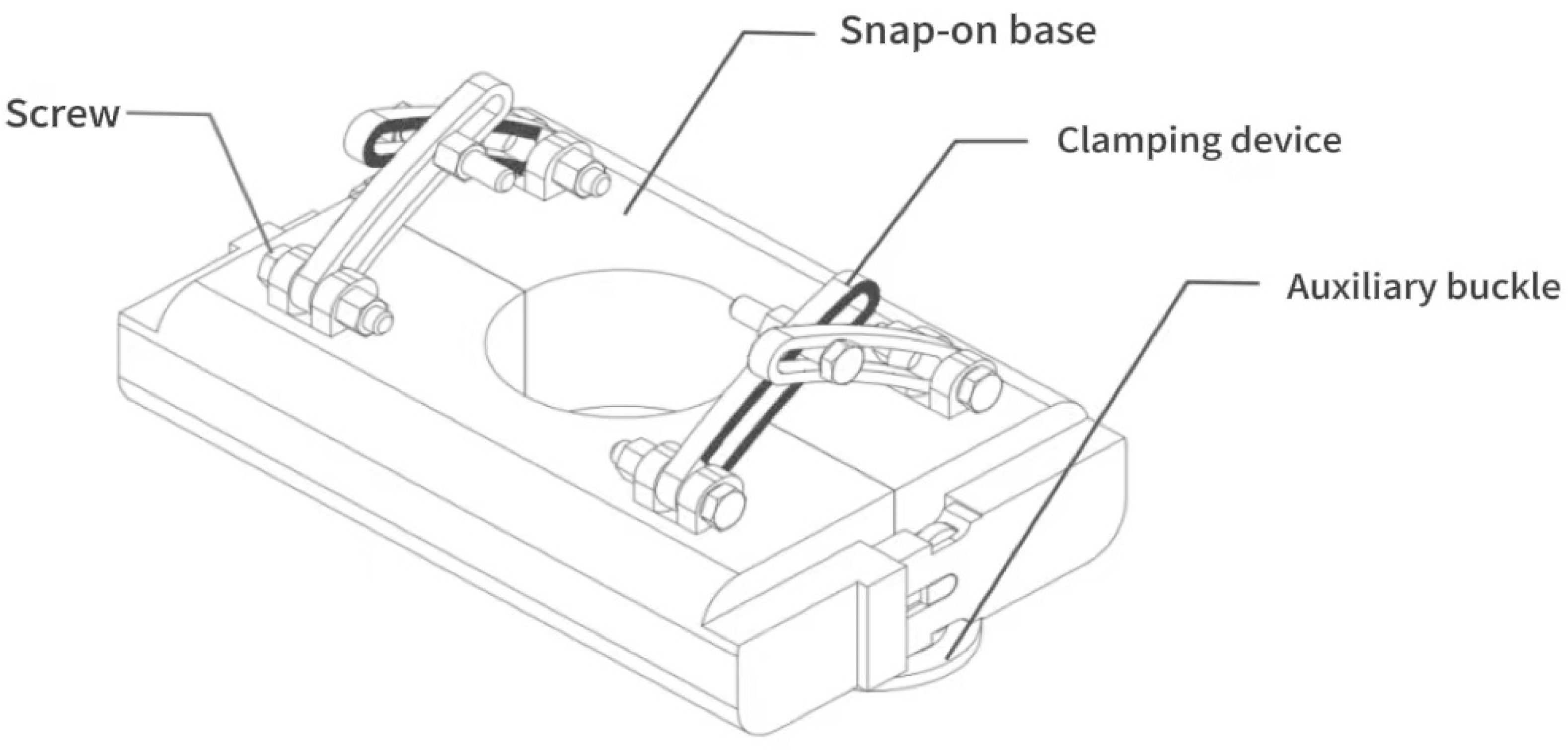
2. Structural Composition and Operating Principle of the Fixing Device

The overhead line fixing device designed in this article mainly consists of two structural components: a snap-fit base and a clamping mechanism. The overall structure of the overhead line fixing device is shown in Figure 1. The base is secured using mechanical interlocking snaps, making disassembly and maintenance more convenient. There are also two auxiliary snaps below the base to assist in securing it, ensuring a more robust fixation. The clamping mechanism is composed of four clamps with protruding rhombus structures. These protruding rhombus structures enhance the engagement strength between the clamps. The shape of the clamps is designed in an arc to better conform to the overhead line, ensuring a more secure fixation of the conductor. The clamps feature infinite adjustment, allowing them to accommodate overhead lines with different diameters within a certain range [7]. The design structure and mechanical performance of this fixture are closely related, and the analysis of its structural composition and mechanical principles is as follows.

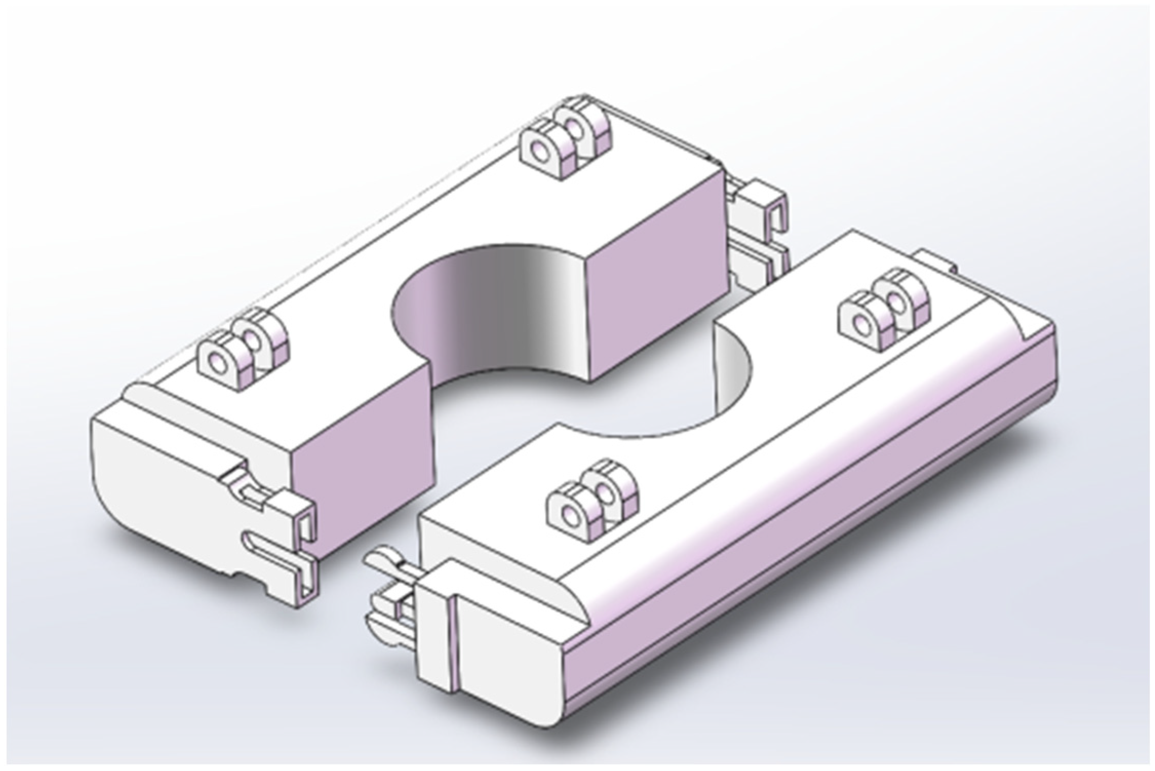
2.1. Base of the Fixed Device

2.1.1. Base Material

In overhead line fixing devices, suitable base materials require good insulation, wear resistance, and corrosion resistance. Common materials include nylon, polycarbonate, and ABS engineering plastics.
Nylon has high mechanical strength and is less likely to deform or damage when under pressure. In the context of securing overhead lines, it is capable of preventing damage caused by pressure and is highly wear-resistant, effectively resisting friction-induced wear and tear over the course of long-term use, thereby extending the service life of the base. However, nylon has relatively weaker resistance to chemical corrosion, and its performance may be affected in environments with strong chemical corrosion. Polycarbonate has strong impact resistance and can withstand external impacts such as collisions and vibrations encountered in overhead line securing devices. However, under high-temperature conditions, its mechanical properties may decrease, and its wear resistance is relatively insufficient. ABS engineering plastic possesses excellent overall performance, exhibiting good resistance to various chemicals and not easily corroded by acids or alkalis, making it suitable for adapting to the complex and changing outdoor climate environment. ABS engineering plastic also has good processing properties, facilitating the creation of bases with various complex shapes through processes such as injection molding [8].
After comprehensive consideration of the usage environment, performance requirements, and cost factors, ABS engineering plastic was ultimately chosen as the material for the base of the overhead line fixing device in this study, to ensure long-term stable operation of the device and guarantee power distribution safety.

2.1.2. Base Form

In the field of power equipment installation, the choice of base types is crucial for both the stability of the equipment and the ease of installation. Common base types currently include flat-plate, track-mounted, and snap-fit types [9].
The flat base is a basic and widely used type, ideal for installation on flat surfaces. Its installation primarily relies on either screw fixation or adhesive bonding. These methods tightly integrate it with the installation surface, securing the equipment in place. This type of base boasts a simple structure and is ideal for scenarios where there are minimal requirements for installation position adjustments and the installation surface is relatively neat. The track base can be used in conjunction with specific cable tray tracks, facilitating convenient and quick installation during the equipment installation process. It enables flexible adjustment of the positions of the fixed points, making it particularly suitable for situations where equipment positions need to be adjusted in a spatial layout, providing great flexibility for installation [10].
This device uses a snap-fit base, and the structure diagram of the snap-fit base is shown in Figure 2. The snap-fit base utilizes dovetail grooves and elastic snap-fit structures to achieve quick fixation through the principle of mechanical interlocking. This design eliminates the traditional cumbersome processes such as tightening screws or applying adhesive, significantly reducing installation time and improving efficiency, with the notable feature of easy installation.
This device has undergone innovative improvements based on the snap-fit base, with an auxiliary latch added beneath the base. The planar structure diagram of the auxiliary latch is shown in Figure 3. The addition of this auxiliary latch not only further enhances the quick installation and removal functionality of the base but also effectively improves the reliability of the base’s fixation. This ensures the stability of the equipment during use and reduces the risk of equipment failures caused by issues such as loosening.

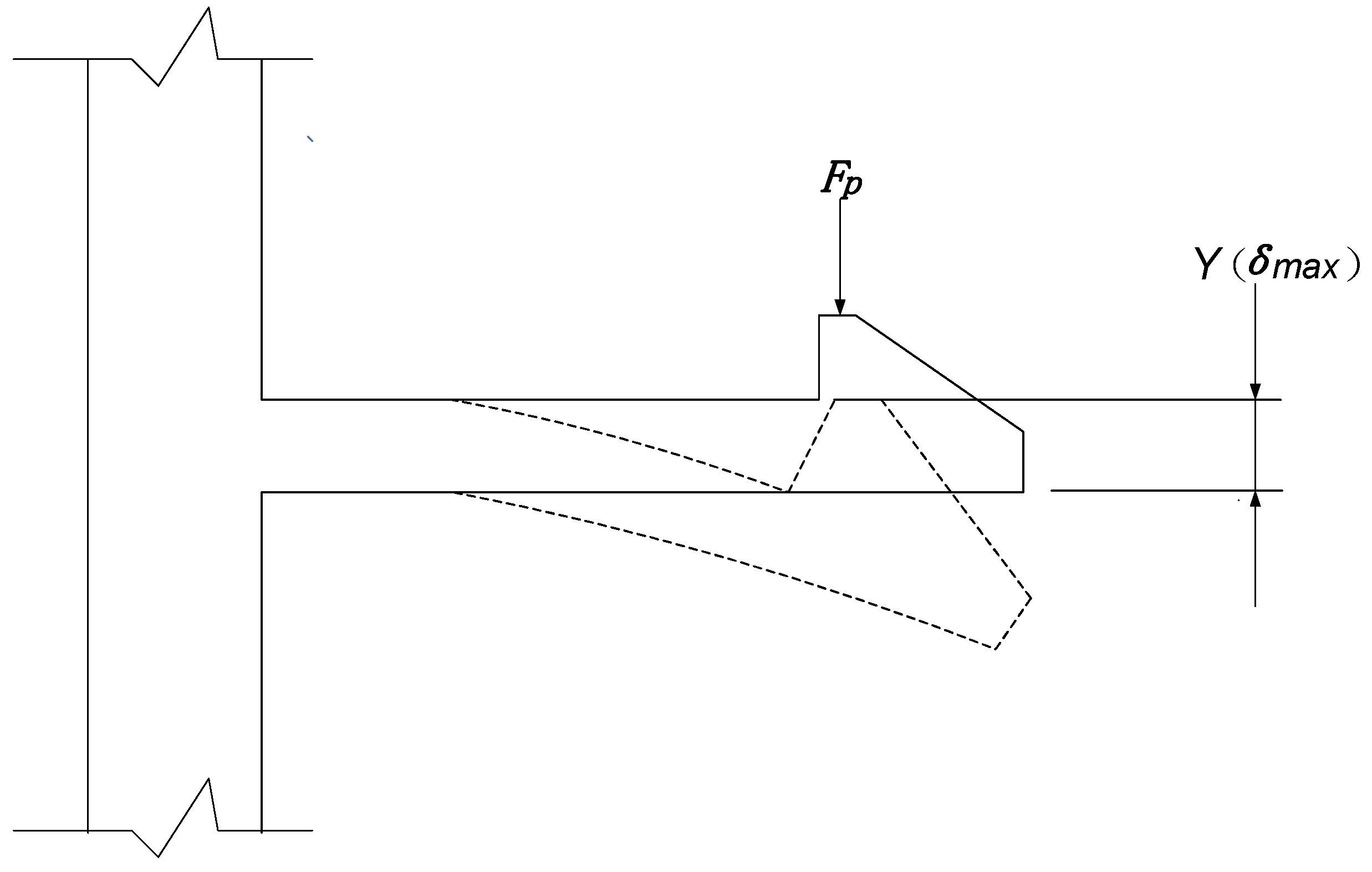
2.1.3. Mechanical Principal Analysis of Base Buckle

The base buckle adopts a cantilever beam structure, which is fixed through mechanical interlocking. An analysis of the force acting on the cantilever beam buckle indicates that its connection reliability is determined by the elastic deformation characteristics of the cantilever beam structure. The schematic diagram of the deflection of the cantilever beam under load is shown in Figure 4.
Based on the theory of material mechanics, a maximum deflection force calculation model is established to determine the relationship between key parameters and structural strength, as shown in Equations (1)–(3).
Equation (1) is based on the deflection formula for the free end of a cantilever beam in materials mechanics δ :
δ = 3 T b Y 2 L b 2
Equation (2) determines the sectional moment of inertia I :
I = W b T b 3 12
After substitution and rearrangement, we obtain the formula for maximum lateral force F p :
F p = W b E 4 T b L b 3 δ
The maximum deflection force F p describes the critical force required to generate a specified deflection amount δ at the end of the cantilever beam buckle, and is used to evaluate the stress limit during the assembly process of the cantilever beam buckle. The cantilever beam latch structure parameter diagram is shown in Figure 5.
In the formula, F p represents the maximum deflection force (N), which is the critical force at which strain occurs at the end of the cantilever beam, W b is the width of the cantilever beam (mm), L b is the length of the cantilever beam (mm), T b is the thickness at the root of the cantilever beam (mm), I is the moment of inertia of the cross-section ( m m 4 ), E is the material’s elastic modulus (MPa), α is the insertion face angle (°), β is the retention face angle (°), and δ denotes the maximum deflection at the end of the cantilever beam (mm), which is typically equal to the depth of the holding plane Y (mm). When it equals the depth of the holding plane Y, it must satisfy δ , the allowable strain-induced deformation corresponding to the material’s maximum permissible strain [11].
The design requires the use of a cantilever beam mechanics model to optimize the size parameters of the latch for achieving a secure latch. To ensure that the base is fixed more securely and better adapts to changes in external extreme environments, the maximum deflection force F p that the cantilever beam latch can withstand should be increased. Therefore, within the limits of the cantilever beam width, the width W b of the cantilever beam can be increased; within the allowable range of the root thickness T b , the thickness at the root can be increased; and the length L b of the cantilever beam can also be shortened, and the maximum deflection amount δ at the tip of the cantilever beam can be increased within the deformation range corresponding to the maximum allowable strain of the material.
The maximum deflection force critical value F p that the end of the cantilever beam clamp can withstand under the conditions of designing the dimensions of the fixed device can be calculated through mechanical performance testing, which is used to evaluate the force limit during the assembly process of the cantilever beam clip. As long as the maximum damage force that the cantilever beam clip can withstand is greater than the maximum destructive force it encounters during actual operation, it will meet the operational requirements under actual working conditions, ensuring the safe and stable operation of the overhead lines.

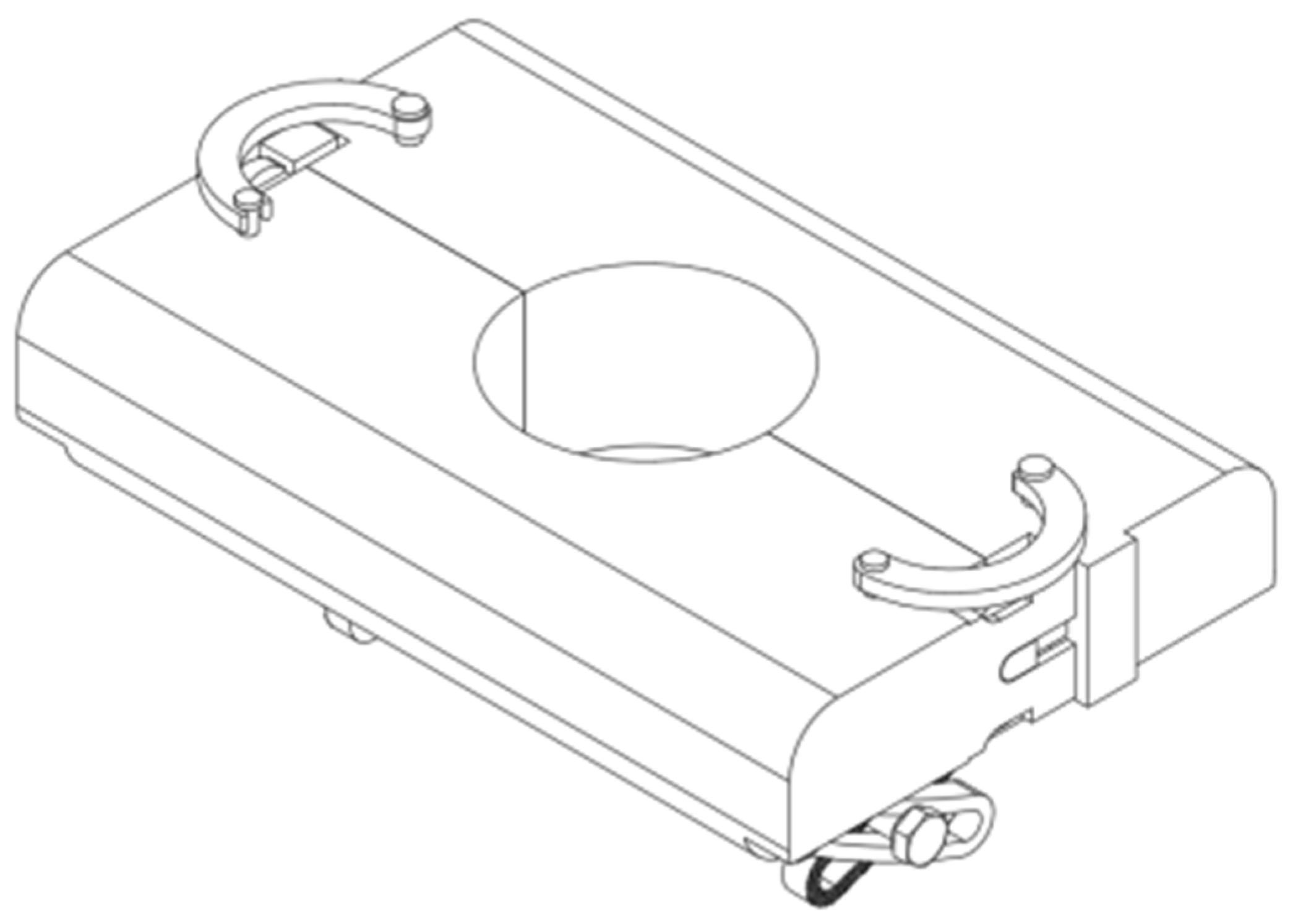
2.2. Clamping Device of the Fixture

2.2.1. Gripper Material

Through mechanical performance testing experiments, the critical value F p corresponding to the deflection δ at the end of the cantilever beam clip can be measured, which is used to evaluate the force limit during the assembly process of the cantilever beam clip. As long as the maximum damage force that the cantilever beam clip can withstand is greater than the maximum destructive force it encounters during actual operation, it will meet the operational requirements under actual working conditions, ensuring the safe and stable operation of the overhead lines.
In the clamping mechanism of overhead line fixtures, the selection of the material for the clamping jaws directly affects the performance, service life, and cost-effectiveness of the device. Stainless steel and ABS engineering plastic are typically chosen for this purpose. Stainless steel has high strength, maintaining structural stability and resisting deformation or fracture under significant external forces. It also boasts good ductility, preventing brittle failure during impacts or vibrations. Additionally, it is corrosion-resistant and heat-resistant. However, stainless steel is relatively heavy, which can be inconvenient in applications with weight restrictions, and it is more expensive. Its harder surface may cause slight scratches on the outer layer of the overhead line during clamping, necessitating the inclusion of additional protective designs, such as rubber linings [12,13].
ABS engineering plastic possesses sufficient strength to meet the basic mechanical requirements for overhead line fixation. It is lightweight, thereby reducing labor intensity and costs during installation and transportation. It also boasts excellent insulation properties, effectively preventing current leakage and enhancing safety. Moreover, it provides strong protection for the outer layer of overhead lines and is cost effective.

2.2.2. Structural Composition

The clamping device of the overhead line fixing device designed in this article consists of four single clamps, ensuring effective fixation of the overhead line while reasonably balancing the overall structural stability and operational convenience of the device. The side structure of the infinitely adjustable clamps is shown in Figure 6. Each single clamp has a round hole at one end, providing an interface for connecting the clamp to the base. By inserting screws into the round holes, the clamps are securely fastened to the base, ensuring that the clamps do not loosen or shift during subsequent use. When fixing the overhead line, tightening the screws causes the clamps to undergo corresponding displacement or deformation, thereby applying clamping force to the overhead line and achieving reliable and precise fixation [14]. The clamps are designed with an infinite adjustment feature, allowing operators to flexibly adjust the tightness of the screws based on the specifications, quantity, and actual installation requirements of the overhead line, achieving the most suitable clamping effect. This ensures the overhead line is securely fixed without being damaged by excessive clamping force.

2.2.3. Mechanical Principal Analysis of Gripper

The gripping mechanism of the fixture consists of four individual grippers, with the protruding diamond-shaped structure of a single gripper illustrated in Figure 7. The magnitude of the force that the gripper can withstand is related to the roughness of the protruding diamond-shaped structure, the engagement strength, and the properties of the materials selected for the gripper. The built-in protruding diamond-shaped structure enhances the roughness of the gripper surface, generating friction between the grippers to achieve a secure hold on the overhead lines.
According to the friction formula:
F f = μ F N
In Equation (4), μ represents the coefficient of friction and F N denotes the force applied to the grippers (N). The greater the frictional force F f (N) between the grippers and the overhead wire, the more effectively it can prevent the overhead wire from sliding during the gripping process. Therefore, by increasing the gripping pressure F N and enhancing the roughness of the protruding diamond structure, that is, increasing the coefficient of friction μ , can increase the frictional force F f , thereby better securing the overhead wire. The inner surface of the gripper is designed in an arc shape to ensure an even distribution of gripping force, preventing localized stress concentration that could damage the insulation layer.
From the perspective of the engagement strength of the protruding diamond structure between the claws, the geometric shape of the diamond allows for a tight interlocking relationship when cooperating with other claws. When multiple claws clamp around an overhead wire, the cooperation with the circular hole and the stepless adjusting screw enables automatic adjustment of the wire diameter within a certain range. The inter-engagement of the protruding diamond structures between the claws achieves a secure grip on the overhead wire, complemented by the curved design of the inner surfaces of the claws, resulting in a clamping device that closely adheres to the overhead wire and possesses high fixing strength.
The magnitude of the force that the gripper can withstand is closely related to the mechanical properties of the selected material. The better the mechanical properties, the greater the force the gripper can bear. From the perspective of the mechanical properties of materials, the essence of the deformation of the gripper is that external forces induce internal stresses, and these stresses drive the material to deform.
Based on the stress–strain relationship:
σ = E ε
In Formula (5), σ represents stress (Pa), reflecting the internal force within the clamp; E is the elastic modulus ( P a ), indicating the material’s resistance to deformation; and ε denotes strain, indicating the degree of deformation. When the material for the gripper is determined, the modulus of elasticity E is fixed. To enable the gripper to withstand greater deformation, the internal structure or composition of the material can be improved, and the design and processing techniques optimized, thereby effectively enhancing its ability to withstand stress [15].
To enhance the tensile strength, flexural strength, and other mechanical properties, the design of the fixing device for ABS engineering plastics may incorporate reinforcing materials such as glass fibers and carbon fibers to improve stress resistance. During the injection molding process, it is essential to appropriately adjust parameters such as temperature, pressure, and cooling rate to minimize internal stresses and defects such as bubbles and shrinkage cavities in the material, thereby achieving a more uniform material structure and enhancing its ability to withstand stress. Additionally, performing an annealing treatment on the molded ABS products, by maintaining them at a specific temperature for a certain duration and then allowing them to cool slowly, can eliminate internal residual stresses, improve the mechanical properties of the material, and enhance its stress resistance.
Based on the lifecycle analysis of fixed devices used outdoors, this paper designs a latch base and clamp jaws made of ABS engineering plastic. Outdoor ultraviolet (UV) radiation can cause the molecular chains of ABS to break, leading to material embrittlement, a decline in mechanical properties, and the appearance of aging and cracking on the surface. In a thermal cycling environment, repeated temperature changes can induce thermal stress, potentially resulting in deformation of the clamp jaws and a reduction in dimensional accuracy. Moreover, the synergistic effect of ultraviolet radiation and thermal cycling can accelerate aging. Chemical modification can be employed to compensate for the weather resistance deficiencies of ABS, addressing issues related to UV degradation and thermal cyclic stress, such as the addition of UV stabilizers. Structural optimization can also be implemented to reduce the erosion of materials due to UV radiation and thermal cycling, while alleviating stress concentration, thereby extending the lifespan of the device by optimizing protective structures. Additionally, improvements in manufacturing processes can minimize material defects and enhance the ability to withstand environmental stresses, such as surface hardening treatments. Furthermore, regular inspections and maintenance are necessary to delay performance degradation, ensuring that the clamp jaws operate reliably in complex outdoor distribution environments, thus meeting the long-term reliability requirements for 10 kV outdoor applications.

3. Installation Method of Fixtures

The installation of the 10 kV overhead line fixing device designed in this article is divided into the following three steps. First, clean the installation surface and place the fixed base at the corresponding position of the insulator; second, push the base firmly to engage the snap-fit, confirm there is no looseness, and then install the auxiliary snap-fit below the base; and finally, place the overhead line into the slot, align the clamp with the overhead line, determine the clamp installation position, and tighten the screws in a specific order.

3.1. Base Installation

The installation of the fixed base is divided into the following four steps. First, clean the installation surface to ensure no dirt or debris and check if the snap-fit base matches the matching components; second, align the snap-fit part of the base with the corresponding structure of the installation cross arm to ensure accurate engagement; third, push the base firmly to fully engage the snap-fit; and finally, install the auxiliary snap-fit below the base for additional fixation.

3.2. Clamping Jaw Installation

The installation of the clamping device is divided into the following four steps. First, ensure the clamp, matching screws, overhead line, and base components are intact and clean, free from oil, dust, and other contaminants; second, align the curved clamping jaw with the overhead line, ensuring the clamp aligns with the corresponding installation position on the base component, and determine the clamp installation position; third, pass the screws through the installation holes above the clamping jaw and the corresponding holes on the base and use a screwdriver to tighten the screws in order to avoid uneven force causing the clamp to install crookedly; and finally, check the alignment of the clamp with the overhead line and the firmness of the installation. There should be no obvious gaps between the clamp and the conductor and gently shaking the clamping jaw should reveal no signs of loosening.

4. Advantages of Fixed Devices

The design of this fixing device is simple, featuring standardization, normalization, safety, reliability, convenient assembly and disassembly, firm clamping force, and adaptability to overhead lines of different diameters. It ensures safe, stable, and aesthetically pleasing power supply for the lines, enhancing the efficiency of line maintenance and the reliability of power supply.

4.1. Advantages of Snap-On Base

The installation of the base can be completed without tools, allowing the buckle to engage directly, significantly reducing installation time and enhancing construction efficiency. The buckle-type base is easy to disassemble, facilitating future maintenance and component replacement, thereby reducing maintenance costs. Beneath the buckle-type base, there is a pair of auxiliary buckles, which enhance the device’s pressure resistance, preventing loosening of the side buckles that could lead to base separation. This ensures long-term stability, making the fixing device more reliable and providing buffer time for device maintenance. The edges of the buckle-type base are designed with a rounded shape, which not only effectively prevents discomfort to hands caused by sharp edges during installation, reducing the risk of accidental abrasions for operators, but also enhances the safety and comfort of the operation process.

4.2. Advantages of Clamping Device

The diamond-shaped structure protruding on the inner side of the clamping jaw can increase the contact friction between the clamping jaws, enhance the meshing strength, prevent the clamping jaws from sliding or loosening, ensure firm fixation, and improve reliability. The clamping jaw adopts an infinitely adjustable adjustment design, allowing the original size of the clamping jaw to be adjusted as needed and the spacing between clamping jaws to be continuously adjusted. It can adapt to overhead lines of various diameters without replacing parts, providing stronger adaptability and flexibility compared to traditional step bolt fixation, thus improving convenience and efficiency. The inner surface of the clamping jaw is designed in an arc shape, which can achieve uniform fit with the outer contour of the overhead line, avoiding local stress concentration, enhancing the stability of fixation, and reducing damage to the insulation layer.

5. Mechanical Simulation Analysis of Fixed Devices

In the overhead lines of the 10 kV distribution network, the mechanical properties of the overhead line fixtures play a crucial role in the operation of the distribution network. When maintenance personnel climb the lines to carry out maintenance work, the fixtures will bear significant vertical pressure, necessitating ensuring their stable operation under various working conditions. This article employs ANSYS 2022 R2 finite element analysis software to conduct a mechanical performance simulation analysis of the 10 kV overhead line fixtures, aiming to verify whether the fixtures can meet the practical engineering application requirements.

5.1. Mechanical Simulation

Using ANSYS software, a model was created based on the actual design dimensions of the 10 kV overhead line fixing device, employing geometric structure settings. The order of the program control unit was set, with the element size specified as 0.5 mm, and mesh adaptivity was activated to optimize mesh distribution. The step control was set to 1 s, with a completion time of 60 s per analysis step, lasting 60 s in total. The initial, minimum, and maximum time steps were all set to 1 s, with each computation step having a time step length of 1 s, considering the inertial effects and enabling time integration. The solver was selected as an iterative solver type; due to sufficient model constraints, there was no occurrence of severe rigid body displacement, and thus, the weak spring was disabled. To account for large deformation effects, large deflection was activated. Reasonable speed dynamic application scenario was set, utilizing the corresponding preset solving parameters to optimize the solving process. The geometric models of the buckle, clamping jaws, and base were accurately constructed, laying the groundwork for subsequent simulation analysis. Considering the actual usage scenario, ABS engineering plastic was selected for the buckles and clamping jaws. The material parameters were set as follows: density at 1.05 g/cm3, elastic modulus at 2 GPa, and Poisson’s ratio at 0.33 [16].

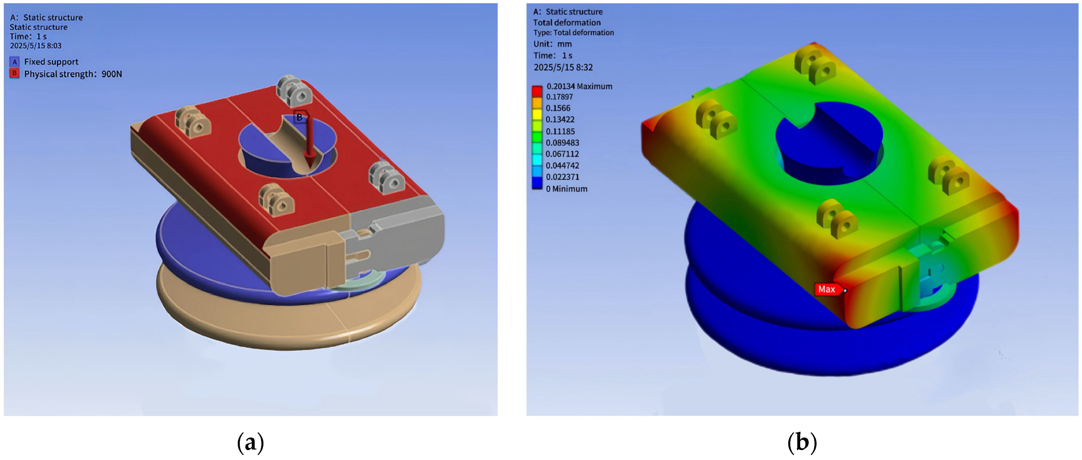
5.1.1. Simulation Analysis of Snap-On Base

The schematic diagram of the base structure design is shown in Figure 8. The base has a concave convex groove structure with a width of 50 mm and a height of 32.5 mm, which can realize the assembly connection between the base and the clamp. The length of the buckle is 22 mm, the height of the buckle is 24 mm, and the elongation rate of ABS engineering plastic is generally around 10–20%. Based on the worst-case scenario of 10%, the maximum deformation that the buckle can withstand in the horizontal direction is 2.2 mm and the maximum deformation that it can withstand in the vertical direction is 2.4 mm.
The maximum vertical pressure that may be exerted on the buckle during simulated maintenance personnel climbing routes and severe natural factors such as typhoons. According to the technical requirements of the ‘Technical Standards for Cable Design in Electric Power Engineering’, the strength requirements for fixed devices under stress must include an additional load of 900 N when there is a brief presence of personnel [17]. The numerical diagram of the vertical dispersion force load applied to the base is shown in Figure 9a. The fixture is installed on the insulator, the base of the insulator is fixed, and the plane of the fixture is subjected to vertical downward pressure as a whole. The vertical dispersion force simulates the situation where climbing personnel apply force during actual operation, where the mechanical properties of the buckle when bearing a large vertical load are tested.
From the deformation numerical graph of the base subjected to a vertical dispersion force of 900 N in Figure 9b, the deformation distribution characteristics of the buckle can be clearly observed. Under this working condition, the maximum deformation of the buckle is about 0.201 mm, and the deformation is mainly concentrated at the four corners of the base arc, because under the action of vertical load the stress concentration at the four corners of the base arc is more obvious, and the buckle base undergoes relatively large elastic deformation in these areas. This maximum deformation is less than the maximum deformation that the buckle can withstand, which is 2.4 mm. This indicates that under the simulated working condition of maintenance personnel climbing the line, the deformation of the buckle is still within a controllable range, which can ensure the reliable fixation of the wire in actual use and will not affect its normal function due to excessive deformation. According to the national 10 kV line safety installation standards, in terms of load-bearing performance, the deformation of the device when subjected to a vertical force of 900 N is much lower than the maximum deformation that the device can withstand, meeting the requirements for the strength and stiffness of fixed devices in the national 10 kV line safety standards, and effectively ensuring the stability and safety of the line during operation and maintenance.
When the operator applies force through a small area contact, the force area is significantly smaller than the bearing surface of the device; that is, there is a concentrated load on the fixed device. If all the weight of the operator passes through the toe, all concentrated on one corner of the fixing device, as shown in Figure 10a, one corner of the fixing device is subjected to 900 N vertical direction concentrated load. In Figure 10b, 900 N vertical direction concentrated load deformation is applied, and it can be seen from the figure that the maximum deformation of the buckle is about 0.234 mm, slightly larger than the deformation of the dispersed load, but still far less than the maximum deformation that the buckle can bear, i.e., 2.4 mm. Thus, the mechanical properties of the concentrated load meet the requirements.
In on-site work, workers are not always stationary on fixed devices, but make various movements. During movement, the acceleration of the human body will produce an instantaneous change in the force of the device, that is, dynamic load. The dynamic stress is higher than the static stress, and its peak value is higher than the static stress, which can usually be analyzed as 2–3 times the static stress. The simulation test shows that the maximum deformation of the buckle is 0.425–0.653 mm, which is still within the range of 2.4 mm. Therefore, whether it is the static line self-weight or the dynamic additional load generated by the operator’s activities, it fully proves the strength that the fixture can bear meets all the requirements of the line installation and maintenance for the load bearing, has reliable mechanical stability, and meets the strength and stiffness requirements of the fixed device in the national 10 kV line safety installation standard for the fixture under complex stress conditions.
To analyze the mechanical performance of the buckle type base under simulation conditions, specific tensile tests need to be conducted to simulate the scenario where the base is subjected to external lateral tensile forces during the operation of overhead lines. By using finite element software to implement loading, with a gradient increment of 1 N, gradually apply force from 0 N until the base trips and test the maximum critical value that the device can withstand. Diagrams of applying external tension to the base buckle are shown in Figure 11 and Figure 12, applying 326 N and 327 N outward tension to the buckle type base, respectively. This process utilizes finite element simulation to restore the real stress environment. By continuously monitoring the mechanical response such as force distribution and deformation of the base, the maximum critical value of the device’s load-bearing capacity is obtained, providing data support for evaluating the mechanical performance of the base and ensuring the reliability of overhead line fastening.
From the mechanical analysis results, as shown in Figure 11a, the load value diagram of the base buckle applying the outer critical tension shows that when a 326 N outer tension is applied to the buckle type base, combined with the deformation value diagram of the base buckle applying the outer critical tension in Figure 11b, the buckle undergoes observable deformation, with a maximum deformation of about 3.033 mm. When the tension is increased to 327 N, corresponding to the load value diagram of the base buckle applying the outer tension in Figure 12a and the detachment deformation value diagram of the base buckle applying the outer tension in Figure 12b, the buckle type base experiences detachment. Simulation experiments show that the critical value for the buckle to withstand external tensile force is 326 N, which is the maximum external tensile force that the buckle can withstand. If this value is exceeded, the integrity of the buckle structure will be damaged, resulting in detachment failure.
Based on the above analysis, the performance analysis of the buckle type base under vertical pressure conditions shows good adaptability, whether under vertical pressure or tested under outward tension conditions. This good mechanical performance under multiple working conditions provides strong technical support for ensuring the fastening of the line and resisting external loads in practical overhead line engineering applications. It can effectively reduce the risks of line loosening and faults caused by insufficient mechanical performance of the base and improve the safety and stability of overhead line operation.
Considering the damage caused to the structure by wind force on the fixed device, the force F on the fixed device under wind force needs to be analyzed using fluid mechanics theory. According to the dynamic pressure formula in fluid mechanics, the formula for a fixed device under wind force is as follows:
F = 1 2 ρ v 2 C d A
In the Formula (6), X is the air density (taken as 1.225 kg/m3 under standard conditions); V is the wind speed (m/s); C d is the drag coefficient, which is related to the shape of the object; and A is the windward area (m2), which needs to be calculated based on the actual object. In practical engineering scenarios, it is necessary to infer the corresponding wind speed conditions to evaluate the wind resistance of fixed devices under specific forces. Assuming that the fixed device is subjected to a 326 N wind force, the schematic diagram of the buckle type base structure is shown in Figure 13. The length of the left view area is 0.159 m and the width is 0.0325 m. Here, the calculation is based on the RA5.0ET250L ceramic cross arm insulator with the maximum cross-sectional area [18].
The cross-sectional length is 0.49 m and the width is approximately 0.080 m, resulting in a cross-sectional area of approximately 0.04437 m2 for the device. By substituting known parameters into the formula, the wind speed v is derived as v = 2 F ρ C d A . According to the formula, under a force of 326 N, the wind speed v is approximately 109.5 m/s, which is greater than the wind speed of a super typhoon of level 17 (61.2 m/s). This result indicates that the fixed device of the overhead line needs to have good wind resistance performance, and its structural strength needs to meet the load requirements of natural extreme weather.

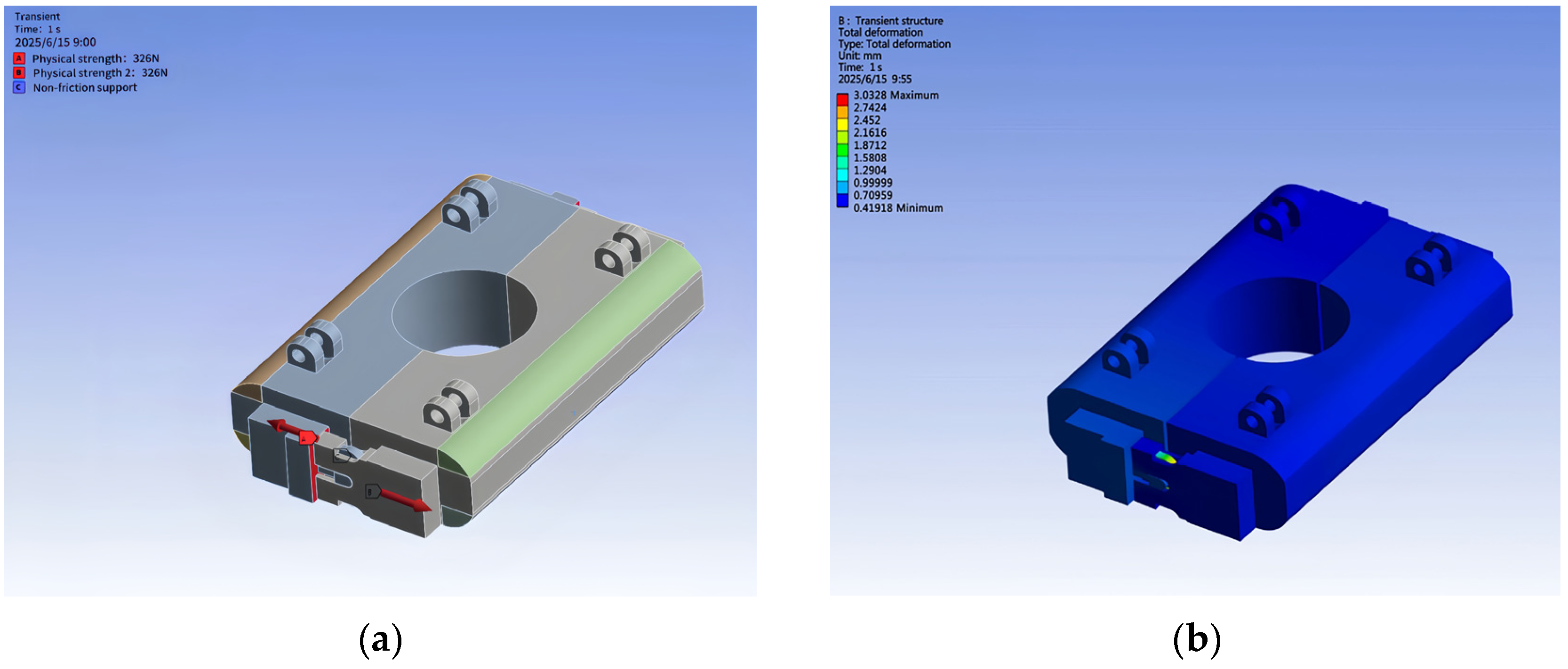
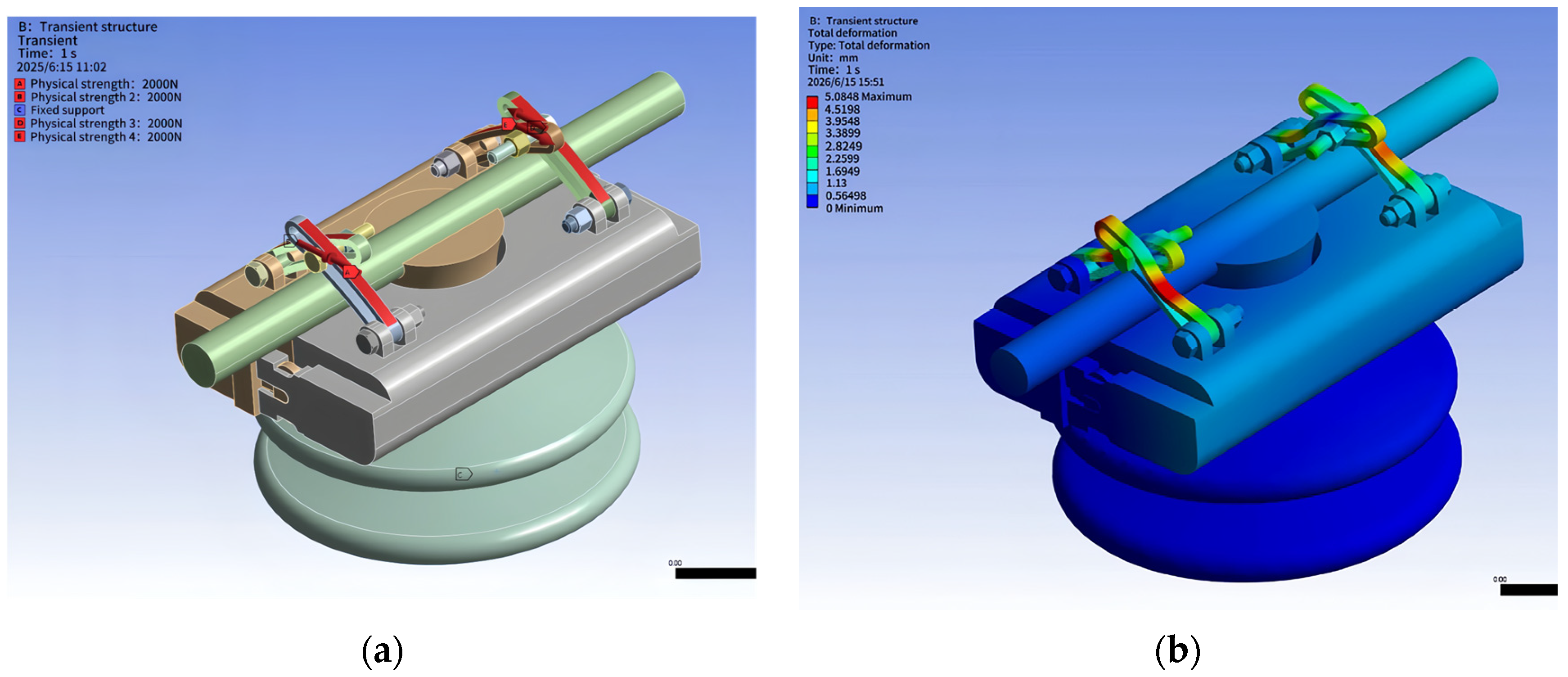
5.1.2. Simulation Analysis of Infinite Adjustment Gripper

The design diagram of the gripper structure is shown in Figure 14. The gripper end has a circular hole structure for inserting screws, which facilitates the assembly and fixation of the gripper with the base. There is a long groove on both sides of the clamp, with a width of 2.5 mm. From the side view, it can be seen that there are some textured lines on the surface of the component, indicating that the clamp surface has a diamond-shaped protrusion structure. When in contact with the overhead line, it enhances the friction between the two and prevents relative sliding. The length of the clamp is 58.44 mm, the width is 10 mm, and the thickness is 4.95 mm. The elongation rate of ABS engineering plastic is taken as 10%. After calculation, it can be concluded that the maximum deformation that the clamp can withstand along the long side is 5.844 mm.
In actual practice, overhead power lines are affected by wind force, and the clamping device will be subjected to tensile force along the vertical direction of the overhead power line. The diagram of applying 2000 N tension along the vertical direction of the overhead line with the clamp is shown in Figure 15. The static load is calculated based on the actual cable diameter, span, and local historical maximum typhoon wind speed, multiplied by a comprehensive safety factor of 2.5. Referring to the conductor wind load in GB-50009 “Code for Load on Building Structures” [19]. when a strong typhoon strikes, the wind force on the line increases dramatically, combined with factors such as line spacing, conductor type, and topography. Moreover, after fully considering the extremely severe working conditions such as strong coastal wind areas, it is simulated that under extreme working conditions, the vertical tensile force borne by the clamping device is 2000 N, while the clamping jaw exerts 2000 N tensile force along the vertical direction of the overhead line, to ensure that it is in harsh natural conditions and possible working scenarios. The strength and stability of the clamping device can still meet the requirements of the standard, and effectively ensure the safe and stable operation of the overhead line.
We applied a tensile force of 2000 N along the vertical direction of the overhead line to the gripper device, as shown in Figure 15a. Under simulated typhoon conditions, the gripper underwent a certain deformation. As shown in Figure 15b, the maximum deformation of the gripper is about 5.085 mm, which is less than the maximum allowable deformation of 58.84 × 10% = 5.844 mm. The national standard for 10 kV overhead line fixtures, in terms of mechanical properties, anti-deformation, etc., requires the device to be controlled within a reasonable range under simulated extreme working conditions, so as to ensure that the line is fixed and stable, and the safety of power transmission is ensured. When the gripper device simulates the typhoon condition and is subjected to 2000 N along the overhead line, the maximum deformation of the gripper is 5.085 mm, which is lower than the 5.844 mm that the gripper can bear, and its deformation is in the safety range allowed by the standard, which can effectively fix the overhead line. From the point of view of the key index of anti-deformation performance, it meets the technical requirements of the national standard for overhead line fixtures with a rated voltage of 10 kV to have reliable stability and ensure line safety under extreme working conditions. Under this condition, the gripper device can stably fix the overhead line without excessive deformation due to external forces, which may cause the overhead line to loosen or fall off. This meets the requirements for fixing overhead lines under dynamic conditions and verifies the reliable stability of the gripper device under extreme weather conditions.
Through finite element analysis, it can be concluded that the deformation of the buckle and gripper under different stress conditions meets the design requirements. The assembly efficiency of the buckle is high, and the diamond-shaped structure of the gripper exhibits superior performance. Through simulation verification, the overhead line fixing device has the advantages of simple structure, convenient loading and unloading, and strong adaptability, which can significantly improve the safety and reliability of 10 kV overhead line operation, and has certain engineering application value.

6. 3D Printed Physical Structure of Fixed Device

This fixed device adopts 3D printing technology, and the device model is designed as a 10 kV overhead line fixed device. The physical object consists of a buckle type base and a clamping device, and the overall structure is shown in Figure 16. The clamping device is composed of four ABS engineering plastic clamps, and the protruding diamond-shaped structure of each clamp increases the contact friction and engagement strength between the clamps. The clamp is fastened to the base by a screw inserted through a circular hole at one end, and its curved inner surface can uniformly fit the outer contour of the overhead line. Coupled with an infinitely adjustable design, it achieves adaptive fixation of overhead lines with different wire diameters.
The physical structure diagram of the buckle type base is shown in Figure 17. It is made of ABS engineering plastic and forms a mechanical bite type quick fixing structure through concave convex grooves and elastic buckle structure. The auxiliary fixed buckle below the base is matched to achieve quick installation and reliable fixation of the base. The edge arc design can avoid hand abrasions during operation. The integrated snap-on base and clamping device of the device have strong fixation performance, which can maintain stability in complex outdoor power distribution environments and ensure stable power transmission.
The physical structure diagram of the buckle type base is shown in Figure 16. It is made of ABS engineering plastic and forms a mechanical bite type quick fixing structure through concave convex grooves and elastic buckle structure. The auxiliary fixed buckle below the base is matched to achieve quick installation and reliable fixation of the base. The edge arc design can avoid hand abrasions during operation. The integrated snap-on base and clamping device of the device have strong fixation performance, which can maintain stability in complex outdoor power distribution environments and ensure stable power transmission.

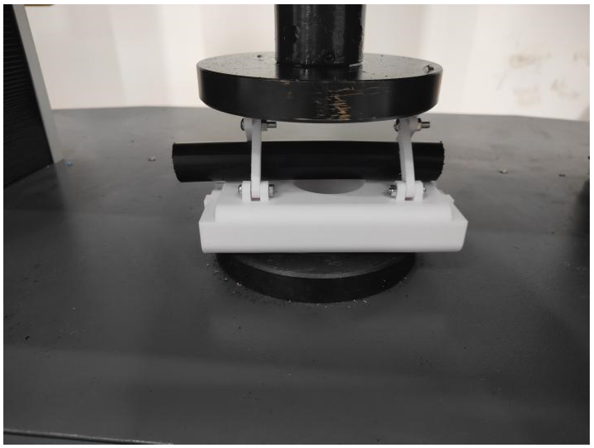
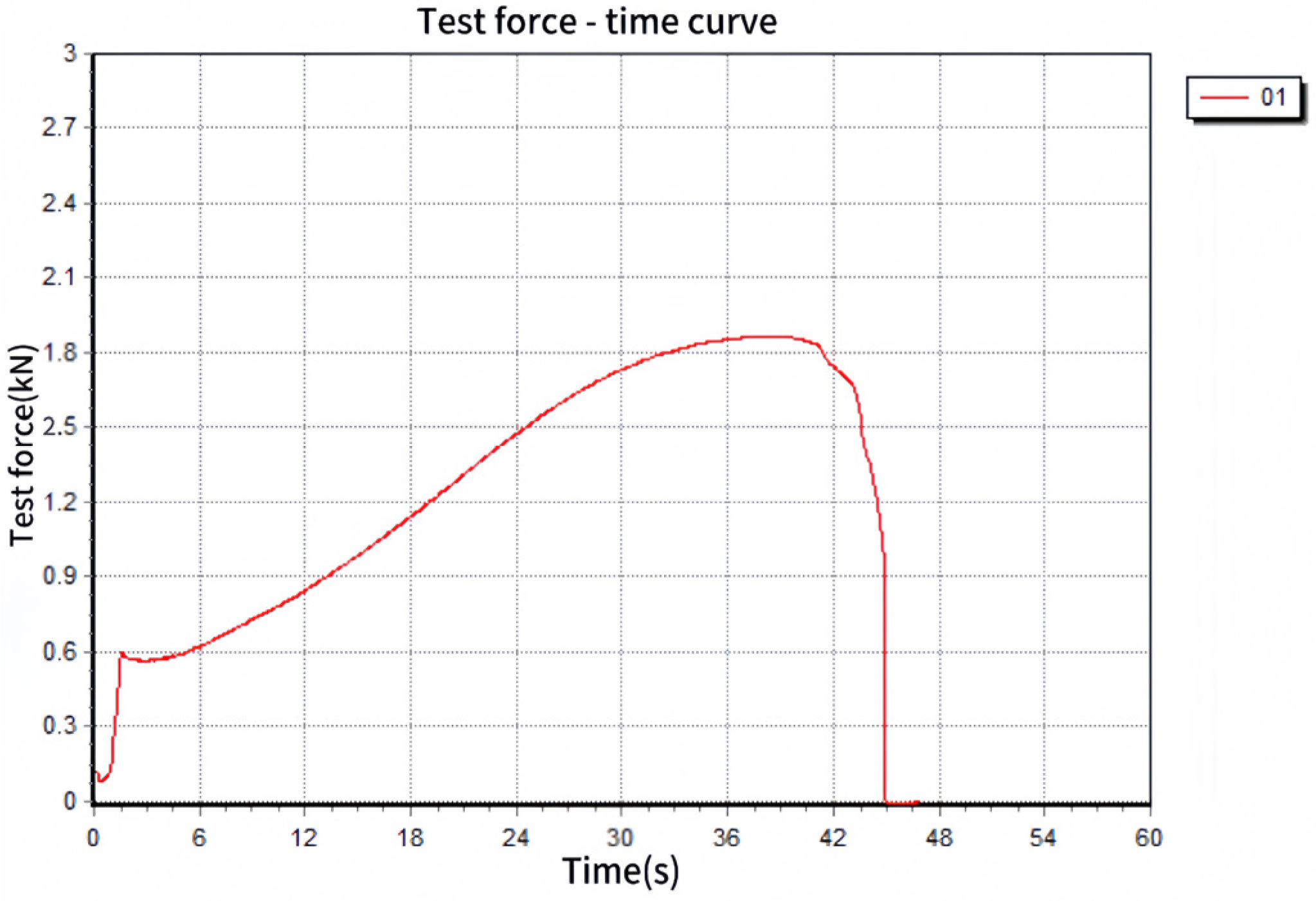
7. Mechanical Performance Testing of Fixed Devices

To verify the mechanical reliability of the 10 kV distribution line fixing device, mechanical tests were conducted on the snap-on base and clamping device, simulating various working conditions of the overhead line fixing device under tension and pressure during actual operation. The mechanical properties of materials are easily affected by temperature and humidity, which may lead to deviations in mechanical indicators during tensile testing. In order to reduce environmental interference and ensure the authenticity and stability of test results, strict control was exercised over the temperature and humidity of the experimental environment during the tensile test. The temperature remained constant at 25 °C throughout the test, and the relative humidity was controlled at 50%, to ensure the test results could truly reflect the mechanical properties of the material in a stable environment and reduce the interference of environmental factors on the test data.

7.1. Test and Analysis of Snap-On Base

The device fixed test adopts the WDW-200B (Jinan Nanok Testing Equipment Co., Ltd., Jinan, China) microcomputer controlled electronic universal testing machine, which is suitable for non-metallic mechanical performance tests such as tension and compression. When operating the tensile testing machine, a non-metallic structure testing program is selected for measurement. The program adopts a force control method, continuously increasing the tension from 0 N. The clamps on both sides clamp the two ends of the buckle base, and continuously stretch the two ends of the base until the fixing device fully pulls the buckle apart. The tensile testing machine test diagram is shown in Figure 18.
The force–time curve of the force test on the buckle base is shown in Figure 19. The test tension gradually increases from 0. When the test time is about 4 s, the recorded peak tension is 250 N. The test is continued until the two buckle bases are completely detached. After the buckle is detached, the test force curve value rapidly decreases until the electronic universal testing machine stops. The mechanical performance of the device is stable within the limit, and the material strength and structural design meet the requirements. However, when the tensile force exceeds the peak, the device’s buckle base will buckle off. Compared with the simulation value 327 N, the experimental value is slightly smaller than the theoretical value, but after calculation and analysis, it can still adapt to extreme typhoon situations on site. The constraints on the fixed end and contact interface in simulation are usually rigid and gapless, but in reality, there are factors such as elastic deformation, small looseness, material defects, and loading disturbances, which lead to simplification errors in boundary conditions. In the simulation, the constraints on the device, such as the rigid constraint on the fixed end, were simplified, while in the experiment, the fixed end of the device had small elastic deformation, resulting in differences between the actual force distribution and the simulation, which in turn affects the peak load and ultimately leads to the measured value being smaller than the theoretical value calculated in the simulation. After calculating the peak tensile force of 250 N and deducing the wind speed v = 2 F ρ C d A , according to the formula, the wind speed v under the force of 250 N is about 95.91 m/s, which is greater than the wind speed of a super typhoon of level 17 (61.2 m/s), and the measured value still meets the requirements of extreme working conditions. It can provide guarantee for the safe operation of 10 kV lines in harsh environments such as typhoons, and has safety standards to resist extreme weather and ensure the stability of the line. It has reliability in practical harsh power engineering applications.
In order to verify the repeated opening and closing of the buckle base and its long-term durability, the buckle structure of the base is simple, and the opening and closing process is stable without obvious fluctuation. The test temperature is controlled at 25 °C, and the relative humidity is controlled at 50%. In order to ensure the effectiveness of error analysis, the buckle base is tested ten times. The tensile test shows that the average pulling force of the buckle base is 251.2 N, the variance is 85.35 N2, the standard deviation is 9.24 N, and the coefficient of variation is 3.68%. The coefficient of variation of the buckle base is less than 5%, indicating that the stability and consistency of the buckle base of the device are good.

7.2. Test and Analysis of Infinite Adjustment Gripper

When conducting pressure testing on the gripper, place the entire test specimen of the power distribution line fixing device under the press and apply pressure, continuously increasing the pressure value. Measure multiple parameters such as test force, peak force, deformation displacement, and test time, and synchronize the test data to the computer. The test diagram of the gripper pressure testing machine fixing device is shown in Figure 20.
The stress curve of the device under compression is shown in Figure 21. When the test time is about 45 s, the recorded pressure peak is about 1860 N. For the test of the 10 kV overhead line fixed device, in the national standard of technical specification for design of 10 kV and below overhead distribution lines, it is clearly required that the fixed device should have sufficient mechanical strength and stability to cope with the line operation and maintenance operation and the load under extreme conditions. Before this pressure peak condition, the device did not show any damage, and the gripper can still meet the clamping strength requirements. Its structural strength can effectively withstand this pressure without failure due to excessive deformation. When the pressure peak is exceeded, the gripper fractures and breaks. This test result fully verifies that the clamp can ensure the stable clamping of overhead lines under various working conditions such as instantaneous loads and long-term stresses, providing a basic guarantee for the safe and reliable operation of overhead lines.
In order to verify the fracture and failure consistency of the clamping claw of the fixture under repeated pressure peak, the test temperature was controlled at 25 °C and the relative humidity was controlled at 50%. In order to ensure the effectiveness of error analysis, the clamping claws were tested for ten times. Through the pressure test, the average fracture pressure of the gripper is 1868.6 N, the variance is 599.04 N2, the standard deviation is 24.47 N, and the coefficient of variation is 1.31%. Through the analysis, the coefficient of variation of the gripper of the fixture is less than 5%, indicating that the stability and consistency of the gripper of the fixture are good.
Based on the above test results, the mechanical performance, i.e., the tensile and compressive values of the 10 kV overhead line fixing device, is within the allowable range, meeting the requirements of the on-site engineering. The collaborative design of the buckle type base and the infinitely adjustable clamp can effectively cope with extreme stress scenarios in actual operation, and the mechanical reliability meets the application requirements of 10 kV overhead line engineering, with good environmental adaptability and structural stability.

8. Conclusions

In response to the problems of wire detachment, insulation layer damage, and low construction efficiency in the traditional fixed line method of 10 kV overhead lines, we have developed a new type of fixing device consisting of a buckle type base and an infinitely adjustable clamp. The base is quickly installed by mechanical interlocking clamps and combined with auxiliary clamps to enhance stability. Its edge arc design improves operational safety, and the protruding diamond structure inside the clamp increases friction coefficient and engagement strength. It is compatible with overhead lines of different diameters with the inner surface of the arc and the infinitely adjustable screw. Through finite element mechanical simulation and microcomputer controlled electronic universal testing machine testing, it meets the mechanical performance requirements. ABS material has shortcomings such as fluctuating performance in extreme environments, potential fatigue cracks in clamps during long-term use, uneven force distribution during screw tightening, time-consuming auxiliary buckle operation, and corrosion in salt spray environments. However, this device has a simple structure, easy installation, firm fixation, and strong adaptability. In the future, its performance can be further improved through material improvement, structural optimization, process upgrading, and intelligent transformation, and it has engineering application value.

Author Contributions

Conceptualization, B.L., S.T., L.C., J.L., L.B., Y.S. and Y.L.; Methodology, B.L., S.T., L.C., J.L., X.Z., Y.S. and L.B.; Software, B.L., S.T. and J.L.; Writing—original draft, B.L., J.L., X.Z., L.C. and Y.L. All authors have read and agreed to the published version of the manuscript.

Funding

This research was funded by the key laboratory of intelligent control technology for Wuling-Mountain ecological agriculture in Hunan Province ZNKZD2024-7, Hunan Provincial Natural Science Foundation Regional Joint Fund project 2024JJ7371, and Key Research Project of Hunan Provincial Department of Education 24A0558.

Data Availability Statement

The original contributions presented in this study are included in the article. Further inquiries can be directed to the corresponding author.

Conflicts of Interest

The authors declare no conflict of interest.

References

  1. Zhang, G.; Qiu, Y.; Zhai, Y. Design of Fixed Devices for Overhead Line Conductors and Insulators in Distribution Networks. Rural. Electr. 2025, 33, 36–37. [Google Scholar] [CrossRef]
  2. Zhao, L.; Qin, X.; Guo, X.; Luo, S.; Zhao, H. Design and Development of a New High Voltage Line Tightener. Electr. Technol. 2021, 114–115. [Google Scholar] [CrossRef]
  3. Shi, M.; Wang, P.; Duan, C.; Chen, Y.; Zhang, M.; Xia, B.; Liu, H.; He, Z. Discussion on a standardized fixed device technology for 10 kV overhead power lines. J. Anhui Electr. Eng. Vocat. Tech. Coll. 2024, 29, 30–35. Available online: https://kns.cnki.net/kcms2/article/abstract?v=lHYhtDVi6z8k6SbQNN3s4HTU7n_yrS5eTQyEJVR6RLdhG_oJCzE8HnhZkFxOCo-N1lomByaN1lWL9LssG_9iIC6qBjeKZ9SCDwl9Jb0DmPdeX3QwXC5bGFXSOqwPGuSuWn6xNZiCrlfXwqdBMZwYEv0KJ7yQVihjbS_VJz7NPC0nQQLpSVgmHw==&uniplatform=NZKPT&language=CHS (accessed on 18 July 2025).
  4. Luo, J.; He, J.; Yang, J. Design and Application of a Wire Fixing Device on Insulators. Integr. Circuit Appl. 2022, 39, 244–245. [Google Scholar] [CrossRef]
  5. Wang, Z.; Li, W.; Li, Y. Research on Fixed Drainage Lines and Jumper Insulation Devices for Live Working of 10kV Distribution Lines. J. Electr. Eng. 2017, 12, 19–23. [Google Scholar] [CrossRef]
  6. Yu, F.; Kai, W.; Shaolei, W. Design of clamping device for overhead line branch line with live installation. In Proceedings of the 2020 International Conference on Artificial Intelligence and Electromechanical Automation (AIEA), Tianjin, China, 26–28 June 2020; IEEE: Piscataway, NJ, USA, 2020; pp. 321–324. [Google Scholar] [CrossRef]
  7. Gong, X.; Zhang, M. Research on Construction Technology for Cable Laying and Installation of 10kV Overhead Distribution Network. Electr. Technol. Econ. 2025, 81–83. Available online: https://kns.cnki.net/kcms2/article/abstract?v=hQuCc5bkPPNRrfYUX_Dgo41iqc0VttEnp--1coZmXGkUJrnveARXPXlJloTYvHIULqUywzvKSArUoihkbDNnAh801nMIazuxCRalyRMamYifspkRNfAftqTJaccx60Oa6H-XYBOMPrOQP0odK7cVIbynFcKUj0yg-E0Rt9DtH17wuHIBF9sRPw==&uniplatform=NZKPT&language=CHS (accessed on 18 July 2025).
  8. Li, G.; Ni, J. Development of 10kV Live Overlapping Lead Fixing Equipment. Zhejiang Electr. Power 2013, 32, 67–69. [Google Scholar] [CrossRef]
  9. Sun, C.; Yang, Y. Development of 10kV Live Working Tools. Yunnan Electr. Power Technol. 2013, 41, 61–63. Available online: https://kns.cnki.net/kcms2/article/abstract?v=lHYhtDVi6z94Q67YeMarprudaG-p74_OGtwZ6buCjqOmw5-vX5iTli_q9-T5jB-C8RZPnJdb1mPQ6cpReg_q3mJcf0BSJCP91xacnptbTrnYOYGv7YY4k7pWhXWWxKK6rOzaJBawFal_x-WUmhJa5aCgbX0lhCjBFpf5LTpiw6-qCrlUIvLBDg==&uniplatform=NZKPT&language=CHS (accessed on 18 July 2025).
  10. Wen, H.; Zhang, J. Development of Fixed Device for Replacing Tension Insulators of Overhead Power Lines. Rural. Electrif. 2022, 66–69. [Google Scholar] [CrossRef]
  11. Zhang, X. Research on Construction Issues and Key Points for High Voltage Overhead Lines. Shandong Ind. Technol. 2018, 153. [Google Scholar] [CrossRef]
  12. Shen, X. Development of a New Type of Line Tightener. Electr. Era 2019, 69–71. Available online: https://kns.cnki.net/kcms2/article/abstract?v=lHYhtDVi6z8kF83EfuezlN_sm68pu7-Pe5dbWSdN49730BFsrUGH_qLUlWgLNYEyWT74LbmjxKj9nFrXoAfXewtVVEQdVOX1RvTgt84yy2pwQ6qoKXHqgRDTsxl-bDI7T3gqLQjBJgCYXs0_x3Y_8ZCC-QSy20pAh-hV4KyP3Uq07lch3-dDeA==&uniplatform=NZKPT&language=CHS (accessed on 18 July 2025).
  13. Ahsan, M.; Baharom, M.N.R.; Khalil, I.U.; Zanial, Z. Simulation-based analysis of electric field characteristics under high-voltage double-circuit and quadrupole overhead transmission lines. J. Electrost. 2025, 135, 104080. [Google Scholar] [CrossRef]
  14. Tingting, J.; Li, D.; Hongjuan, X.; Zhong, W. Study on the influence of aging and high impedance faults on line loss of 10kV distribution line. IOP Conf. Ser. Earth Environ. Sci. 2019, 233, 022016. [Google Scholar] [CrossRef]
  15. He, Y.; Huang, Y.; Cai, J.; Chen, Z. A Numerical Analysis on the Wind-Resistance Strengthening with Guy Wires for Distribution Lines. In Proceedings of the 2017 International Conference on Manufacturing Engineering and Intelligent Materials (ICMEIM 2017), Guangzhou, China, 25–26 February 2017. [Google Scholar] [CrossRef]
  16. Tian, C. Research on Relay Protection Configuration and Setting of 10kV Distribution Lines Based on High Reliability. Power Equip. Manag. 2025, 154–156. Available online: https://kns.cnki.net/kcms2/article/abstract?v=lHYhtDVi6z_WMgydJD2ydZSZMKf2jRoBFX01ebLrbb89VC9Nik-RxowZUjWSp9nAXQ_w_DUiJ5naClVRPlttekVNg8KSpQUQDQtFqae6Ie9boXv3IG8MaxDRI43LiZyN3IniqD82Edhcs36I5Agm_7xvOBhn3hq0ignZti49H85o_A7-oc64pw==&uniplatform=NZKPT&language=CHS (accessed on 18 July 2025).
  17. GB 50217-2018; Design Standard for Power Engineering Cables. China Planning Press: Beijing, China, 2018. Available online: https://kns.cnki.net/kcms2/article/abstract?v=lHYhtDVi6z_LjccH5l0sH9VpCxWPsO97HaQoTBKISqloTYZ-ebvgo0HccDk60rSkDOv72DmBJuQSmuLJvq5mJSFx8sTFKMRBzJ9QEIFDZOcBplXgNGk5fCczDBeN3kCs-p53dhjvQk59bMN11kmkO3oRqK1stZIj9V8UkdGmtgo=&uniplatform=NZKPT&language=CHS (accessed on 18 July 2025).
  18. Zhang, A. Fixed Device for Insulators and Conductors in Distribution Lines Shandong Province, State Grid Shandong Electric Power Company Changle County Power Supply Company. 26 April 2021. Available online: https://kns.cnki.net/kcms2/article/abstract?v=lHYhtDVi6z_vrhrB_4RX5hazY5FjlLTJomY-6Pn5G1XnH2sfXxZkx27-cii-D16c5DcikI2Mzdv6D3zNqePFvV-DzQ7ZdAcZidPBWTL4qtIZ2dGWebs6kFfHSZZML75rTka9_FjWvm4a5IXCT57eXpynpLik87DISf1Qxtaq4CWW2bINv0rrdQ==&uniplatform=NZKPT&language=CHS (accessed on 18 July 2025).
  19. GB50009-2001; Code for Load of Building Structures GB50009-2001. China Academy of Building Research: Beijing, China, 2007. Available online: https://kns.cnki.net/kcms2/article/abstract?v=hQuCc5bkPPNQjLuRqXAWqkN-KXNejkSBu9TrBXYAjR2g7HVctqRcU_RAl8IJrKv2TISerLHVFPXPSf0WgtW9uL2FC5KkomGD4Dl1i9LZITLuL3ydSVltFP5Lpuiq0bgJBU9Vqn0edfhobzKeMYH1LPmgKUQQB5nlHEYk4Ki4BCFhQ1r_KcQ1xY6TM2YQpxX7UdO-49QZ0vM=&uniplatform=NZKPT (accessed on 21 July 2025).
Figure 1. Overall structural diagram of the overhead line fixing device.
Processes 13 02379 g001
Figure 2. Structural diagram of snap-on base.
Processes 13 02379 g002
Figure 3. Plan structure diagram of the auxiliary buckle.
Processes 13 02379 g003
Figure 4. Deflection diagram of a cantilever beam under loading.
Processes 13 02379 g004
Figure 5. Parameter diagram of the cantilever beam snap-fit structure.
Processes 13 02379 g005
Figure 6. Side structure diagram of the infinitely adjustable gripper.
Processes 13 02379 g006
Figure 7. Diagram of a single gripper with a raised rhombus structure.
Processes 13 02379 g007
Figure 8. Schematic diagram of the concave convex groove base structure.
Processes 13 02379 g008
Figure 9. Force diagram of applying 900 N dispersion force in the vertical direction on the base: (a) Load numerical diagram; (b) Deformation numerical diagram.
Processes 13 02379 g009
Figure 10. Diagram of applying a concentrated force of 900 N in the vertical direction on one corner of the base: (a) Load value diagram; (b) Deformation numerical chart.
Processes 13 02379 g010
Figure 11. Diagram of the critical 326 N tensile force applied to the outer side of the base buckle: (a) Load value diagram; (b) Deformation numerical chart.
Processes 13 02379 g011
Figure 12. Diagram of external 327 N tensile force applied to the base buckle: (a) Load value diagram; (b) Numerical diagram of detachment deformation.
Processes 13 02379 g012
Figure 13. Schematic diagram of buckle type base structure: (a) Front view; (b) Left view.
Processes 13 02379 g013
Figure 14. Gripper structure design diagram.
Processes 13 02379 g014
Figure 15. Diagram of 2000 N vertical tension applied by the gripper along the overhead line: (a) Load value diagram; (b) Deformation value diagram.
Processes 13 02379 g015
Figure 16. Overall structure diagram of the fixed device.
Processes 13 02379 g016
Figure 17. Physical structural diagram of snap-on base.
Processes 13 02379 g017
Figure 18. Test diagram of the buckle base tensile testing machine.
Processes 13 02379 g018
Figure 19. Tensile curve of the fixed device buckle base.
Processes 13 02379 g019
Figure 20. Test diagram of the fixed device of the gripper pressure testing machine.
Processes 13 02379 g020
Figure 21. Pressure curve of the gripper of the fixed device.
Processes 13 02379 g021
Disclaimer/Publisher’s Note: The statements, opinions and data contained in all publications are solely those of the individual author(s) and contributor(s) and not of MDPI and/or the editor(s). MDPI and/or the editor(s) disclaim responsibility for any injury to people or property resulting from any ideas, methods, instructions or products referred to in the content.

