1. Introduction
Marine biofouling—the unwanted buildup of microorganisms, algae, plants, and small animals on submerged surfaces—has been a persistent engineering problem since the earliest days of seafaring. This issue dates back thousands of years, with early civilizations like the Phoenicians using lead and copper sheathing to protect wooden ships from biological growth [
1]. Despite the ancient roots of this problem, it remains highly relevant in modern marine engineering, particularly for structures constructed from polymers. Advanced polymer compositions have been studied in high-stress industrial contexts such as petroleum engineering, where mechanical resilience under dynamic loading is critical [
2]. This highlights the broader relevance of optimizing polymer behavior under environmental and operational stressors. These include systems such as Vortex-Induced Vibration (VIV) suppressors, which rely on precise hydrodynamic properties to function correctly. Even minor surface alterations caused by fouling can significantly reduce their performance, increase maintenance costs, and in some cases, lead to structural failure.
Traditional antifouling strategies have centered around copper-based coatings due to their well-established biocidal efficacy and have been carried from steel structures into modern polymer-based structures. However, the limitations of these systems are becoming increasingly apparent. These coatings typically require multilayer applications including a primer, basecoat, and topcoat, which increase labor demands and material usage [
1] Because polymer structures tend to be more flexible than metals, they are prone to mechanical damage. This flexibility makes polymer coatings especially vulnerable to chipping, scratching, and delamination under operational stresses [
3]. The environmental footprint of these coatings is another major concern, as copper leaching and VOC emissions during application contribute to ecological degradation [
4].
Recent innovations in polymer processing have introduced a compelling alternative: the direct incorporation of Cu
2O into the polymer matrix during manufacturing. This method eliminates the need for separate coating layers by embedding the antifouling agent into the structure itself. Our previous work has demonstrated the efficacy of this approach in controlled settings, showing that it offers sustained biocidal activity while also maintaining mechanical durability. With the advancement of manufacturing techniques, particularly rotational molding and nanoparticle dispersion technologies, this integrated method is now more feasible than ever for real-world applications [
5]. Recent discussions with two international suppliers indicate that the cradle-to-gate cost of the embedded Cu
2O solution (System 2) is USD 18.6/m
2, compared with USD 22.3/m
2 for the multilayer coating (System 1) over a five-year service interval, further supporting the claim that System 2 is both sustainable and economically robust.
When selecting between antifouling systems, efficacy alone is no longer sufficient. As environmental accountability becomes more central to engineering practice, metrics such as global warming potential, cumulative energy demand, and marine aquatic ecotoxicity potential must be factored into material selection and lifecycle design [
6]. Recyclability is also a critical consideration, especially given the growing global focus on circular material flows. Additionally, the system’s resilience to physical damage (e.g., scratching, chipping, and cracking) plays a major role in long-term performance and maintenance requirements, particularly in dynamic marine environments.
Recent life cycle assessments of antifouling technologies reveal substantial variability in environmental performance, yet few studies fully normalize impacts to the surface area. Almeida et al. conducted a comparative LCA of copper-free marine coatings, highlighting reductions in GWP but leaving toxicity trade-offs largely unquantified [
7]. Narasimhan et al. examined energy and toxicity trade-offs in nanostructured foul-release surfaces, noting challenges in balancing manufacturing energy intensity with ecological benefits [
8]. Karlsson et al. evaluated photocatalytic antifouling coatings, emphasizing their energy and material demands but not their performance per unit of biocide [
9]. Uzun et al. (2019) explored end-of-life scenarios for polymeric hull coatings, underscoring the influence of recycling and incineration pathways on cumulative energy demand [
10]. However, none of these studies expressed GWP, CED, or MAETP on a per-kilogram-of-copper or functional biocide basis—metrics critical for assessing embedded systems. The current study addresses this gap through a cradle-to-grave, Monte Carlo-based LCA of two antifouling systems and reports all midpoint indicators normalized both per square meter for a year of hull protection and per kilogram of Cu
2O. The primary objectives are to (i) quantify trade-offs in energy, emissions, and toxicity between a conventional ablative coating (System 1) and an embedded Cu
2O within HDPE laminate (System 2); (ii) identify hotspots in production and end-of-life stages; and (iii) establish normalized metrics to support future comparison with copper-free alternatives.
This study presents a comparative LCA of two antifouling strategies: (1) a conventional multilayer copper-based coating applied to a polymer substrate (System 1) and (2) a novel Cu2O-impregnated polymer structure (System 2). Using ISO 14040-compliant methodology, this work examines the systems across four lifecycle stages—production, application, use/maintenance, and end-of-life—while focusing on their impacts in terms of GWP, MAETP, CED, recyclability, and mechanical durability. The goal is to provide a more holistic evaluation to guide material selection for future marine antifouling systems.
To provide a comprehensive and functionally relevant comparison of the two antifouling systems, three environmental impact criteria were selected: global warming potential, cumulative energy demand, and marine aquatic ecotoxicity potential. These categories were chosen based on their relevance to material production, operational behavior, and end-of-life pathways, particularly for marine antifoulants that behave similarly to pesticide systems in terms of environmental dispersion and toxicology. These three impact factors have been consistently used in similar studies citing their global use in life cycle analysis as seen in
Table 1 below.
1.1. Marine Aquatic Ecotoxicity Potential
Antifoulants are biologically active substances classified as marine biocides by regulatory agencies such as the U.S. Environmental Protection Agency (EPA). MAETP captures the environmental burden posed by the release of these substances—particularly copper ions and volatile organic compounds (VOCs)—on marine ecosystems. Factors influencing MAETP include the inherent aquatic toxicity of the compounds, their persistence and degradability in seawater, bioaccumulation potential, and the timing and rate of their release. While the use phase typically dominates MAETP due to copper leaching, a full life cycle perspective is essential to capture upstream and downstream contributions [
11]. MAETP is expressed in comparative toxic units (CTU) in kg 1,4-dichlorobenzene equivalents (DCB-eq) using the CML 2016 method, enabling clear comparisons across systems and materials.
1.2. Cumulative Energy Demand
CED accounts for the total non-renewable energy input required throughout a product’s lifecycle—from raw material extraction and processing to application and end-of-life treatment. It serves as an upstream proxy for both resource intensity and indirect emissions. Measured in megajoules per functional unit (MJ-eq), CED is particularly useful for identifying energy hotspots in manufacturing, transport, or recycling stages. In antifouling systems, coating synthesis, solvent use, and application energy represent key contributors to CED. This metric is also a key driver of a system’s overall carbon footprint.
1.3. Global Warming Potential
GWP quantifies the cumulative contribution of greenhouse gas emissions over the entire life cycle of the system, normalized to carbon dioxide equivalents (kg CO2-eq). As a midpoint indicator, it is useful for evaluating how material and process choices impact climate change. For antifouling systems, GWP sources include combustion-based electricity used in manufacturing and application processes, chemical decomposition reactions, solvent emissions, and transportation fuels. Comparing GWP values provides direct insight into the atmospheric burden associated with each implementation strategy.
1.4. Life Cycle Analysis as a Comparative Tool
A life cycle assessment was selected as the analytical framework due to its ability to quantify cradle-to-grave environmental impacts, accounting for all relevant phases including raw material sourcing, production, use, and end-of-life processing. According to [
6], LCA is “well suited to compare the severity of different exposure pathways to pesticides,” making it especially appropriate for evaluating systems designed to slowly release biocidal agents into aquatic environments. The methodology used adheres to ISO 14040 standards, ensuring transparent, reproducible, and decision-relevant insights.
2. Experimental/Materials and Methods
2.1. System Design and Functional Unit Definition
This study compares two antifouling systems applied to high-density polyethylene (HDPE) marine structures. These systems differ in their method of Cu2O integration:
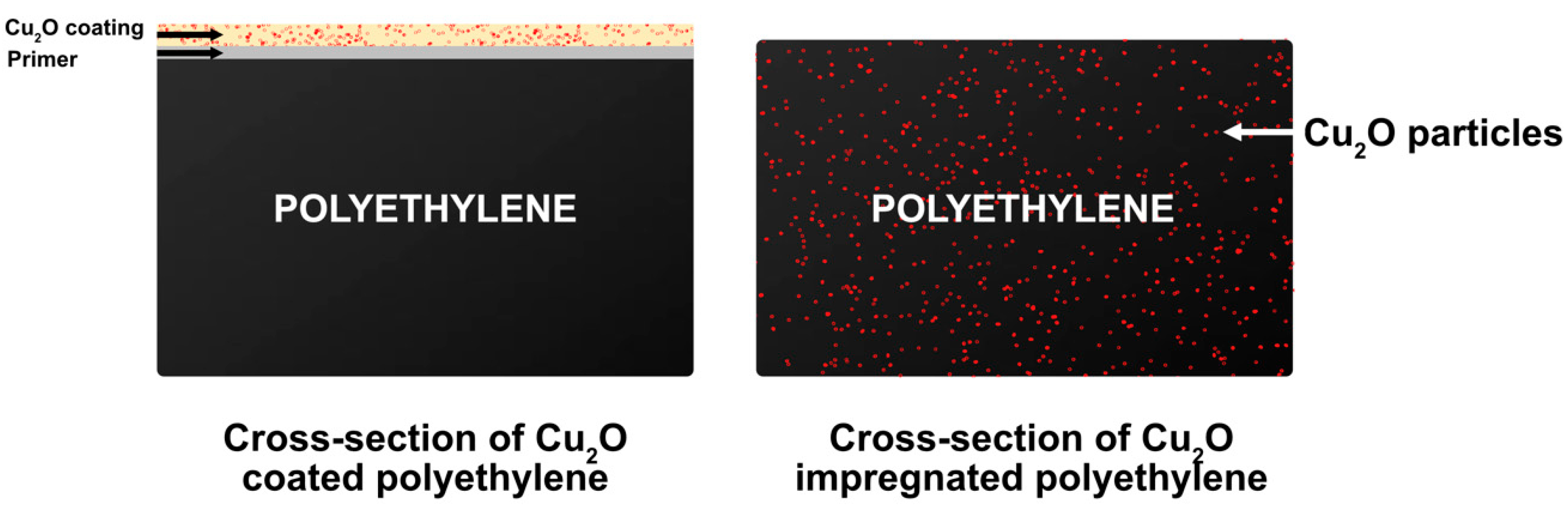
System 1 (Traditional Coating System): Cu2O is incorporated into a coating matrix that is applied to a high molecular weight (200,000–300,000 g/mol) HDPE structure pre-treated with a primer layer consistent with common marine-grade materials. This approach involves multiple processing steps, including sand-blasting surface preparation, epoxy priming, airless spray coating, and cuprous oxide powder coating.
System 2 (Embedded Polymer System): Cu2O is directly incorporated into the HDPE matrix during rotational molding. System 2 is modeled as manufactured by Buffalo Technology Group with Dow DMDA-8922 HDPE. This single-step process disperses Cu2O at a 10% by weight concentration uniformly throughout the polymer body, resulting in a fully integrated antifouling structure.
A schematic cross-sectional comparison is presented in
Figure 1, illustrating material distribution and layer structure in both systems. Substrate thickness is equal on both systems at 6.4 mm, with System 1 adding 50 microns in from the primer and 110 microns from the coating.
To normalize environmental impacts and enable a direct comparison between systems, we selected a functional unit of 1 m
2 of treated surface with an assumed 5-year operational lifespan. Geographic variation in biofouling rates was not incorporated, as the comparative LCA focused on product-level environmental impacts under standardized usage assumptions rather than regional fouling dynamics. This unit is representative of typical use cases in marine structural components and aligns with durability claims from manufacturers of System 1 and prior efficacy studies of System 2 [
11,
12].
2.2. Life Cycle Assessment Framework
This study follows ISO 14040 and ISO 14044 standards for life cycle assessment, comprising four distinct phases: goal and scope definition, life cycle inventory (LCI), life cycle impact assessment (LCIA), and interpretation of results [
13]. The LCA is conducted using OpenLCA software, with data sourced primarily from the Ecoinvent 3.8 database and supplemented with values derived from literature [
11,
14].
A cradle-to-grave system boundary is adopted for both systems to capture all relevant environmental burdens. This includes the following:
Production Phase: Raw material extraction, Cu2O synthesis, primer/coating formulation (System 1), and polymer compounding (System 2).
Application Phase: Surface preparation, coating application (System 1), and molding (System 2).
Use and Maintenance Phase: Emissions during operational service, such as Cu leaching and VOC release.
End-of-Life Phase: Removal, cleaning, and recycling/disposal of materials, including coating disposal per EPA regulations.
It is important to not only evaluate divergence points in the two systems, as examining the common points may yield insight into what phases most contribute to each system’s environmental impact.
2.3. Life Cycle Inventory and Assumptions
Table 2 shows the mass of each material used in the fabrication process for System 1 and System 2. While System 1 values are obtained from Jotun TDS documents, System 2 assumes 10 wt% Cu
2O loading, of which 30% is recycled, which is derived from industry standards and previous experimental work [
15]. A commonly used and representative Jotun primer and coating are chosen for System 1, and all values are normalized to the functional unit as shown in
Table 2.
Energy consumption per stage was calculated using Ecoinvent default values and supplemental values from the literature [
14]. Electrical generation methods were assumed identical in both systems, with surface preparation and primer and coating spraying for System 1 accounting for 0.0028 kWh and 0.0057 kWh, respectively, and Cu
2O blending/stirring accounting for 0.051 kWh/kg in System 1 and 0.018–0.032 kWh/kg in System 2.
While the material masses differ, each system is designed to deliver equivalent antifouling efficacy over a 5-year lifespan. The quantities of Cu
2O used in each system reflect current industry-standard formulations and are supported by prior experimental evaluation by [
15] and were modeled accordingly in the life cycle inventory. Leach rate data were derived from literature values under oxic/anoxic conditions [
12]. System 1 was estimated to leach 0.264 kg Cu
2O over five years, compared to 0.149 kg for System 2. System 2’s leach rate is assumed based upon previous experimentation and values in the literature [
12,
16,
17,
18]. Variability in System 2’s leach rate was more thoroughly examined with each impact category’s sensitivity within the published range. VOC emissions of 194 mg/m
2/day were reported for System 1.
2.4. LCA Phases and Evaluation Metrics
The Production Phase covers raw material extraction, pigment manufacturing (electrolytic Cu
2O), and polymer processing. The high environmental impact of Cu
2O manufacturing was noted, with ~3.5 kWh per functional unit in System 1 [
12].
The Application Phase for System 1 involves three major steps: priming, coating, and curing, each requiring additional energy, equipment, and skilled labor. Overspray and waste are included in the impact. In contrast, System 2 simplifies application via a single-step molding process.
The Use and Maintenance Phase tracks material leaching and surface integrity over time. System 1 has higher MAETP values due to continuous leaching of copper and VOCs. System 2 demonstrates reduced metal release due to internalized Cu2O.
The End-of-Life Phase for both systems includes HDPE removal and recycling, but System 1 requires additional coating removal and disposal compliant with hazardous waste protocols [
19]. System 2 has shown recyclability of 30% ± 5% from recent case studies, which was expanded by an additional 5% in either direction during the sensitivity analysis [
20,
21]. Additionally, copper scrap recovery from System 2 was estimated at 0.283 kg, enhancing recyclability metrics.
2.5. Impact Categories and Characterization
Three environmental impact categories were evaluated using the CML 2016 methodology:
Global Warming Potential: Expressed in kg CO2-equivalents per m2. Captures total greenhouse gas emissions.
Cumulative Energy Demand: Expressed in MJ-equivalents. Indicates non-renewable energy inputs.
Marine Aquatic Ecotoxicity Potential: Expressed in kg 1,4-DCB equivalents. Quantifies aquatic toxicity from leached biocides.
2.6. Data Sources and Software
OpenLCA was utilized for modeling and impact characterization, referencing Ecoinvent 3.8 for background processes. LCI data for System 1 was adapted from existing commercial coatings and recent studies, while System 2 data was aggregated from primary research [
5,
11,
12]. Monte Carlo simulations were run with 1000 iterations to account for variability in inputs, and disputed or inconsistent values were analyzed for impact during the sensitivity analysis.
2.7. Assumptions and Limitations
Both systems are assumed to have equal antifouling efficacy over the 5-year period, as indicated from previous experimental work performed by the authors. Transport impacts were minimized by selecting a shared application location with equal distance from the use site for both systems. Polymer degradation or mechanical failure rates were not included, as this is highly variable and not addressed in similar LCA studies.
MAETP characterization assumes full aquatic availability of leached metals, drawing from leach studies performed on both system types [
12]. Separate studies performed by the authors and Rossini et al. confirm a similar degradation in leach rate over the two systems through their efficacy adjustments over a 5-year lifespan. Although recycling is considered in sensitivity scenarios, the system boundary remains cradle-to-grave since recycled material is not looped back into a second use phase but modeled using system expansion to credit avoided virgin production. This study does not model biological adhesion mechanisms directly, but instead assumes equivalent antifouling efficacy based on prior empirical data. The focus of the LCA is on environmental impact across the product life cycle.
3. Results and Discussion
This study assessed the environmental impacts of two antifouling systems using a cradle-to-grave LCA. The results demonstrate clear differences between System 1 (traditional copper-based coating on a polyethylene structure) and System 2 (Cu
2O-impregnated polyethylene) in terms of GWP, MAETP, and CED. These results are summarized in
Figure 2 and interpreted below.
Figure 2 indicates that the manufacturing stage contributes over 90% of the CED of GWP for both System 1 and System 2, and that while the application stage varies greatly between the two systems, it has a minimal contribution to any of the impact factors measured. This is due to the heavy impact on each environmental factor from the manufacturing and use stages.
System 2 outperformed System 1 across all evaluated environmental impact categories. Specifically, the embedded Cu2O-HDPE system (System 2) achieved a 21.8% reduction in Global Warming Potential, lowering emissions from 5.65 kg CO2-equivalents to 4.42 kg CO2-equivalents per functional unit. Marine Aquatic Ecotoxicity Potential showed the most substantial improvement, decreasing by 30.4% from 4.70 × 10⁵ to 3.27 × 10⁵ kg 1,4-dichlorobenzene equivalents. Additionally, cumulative energy demand was reduced by 17.3%, with energy use falling from 91.0 to 75.3 MJ-equivalents.
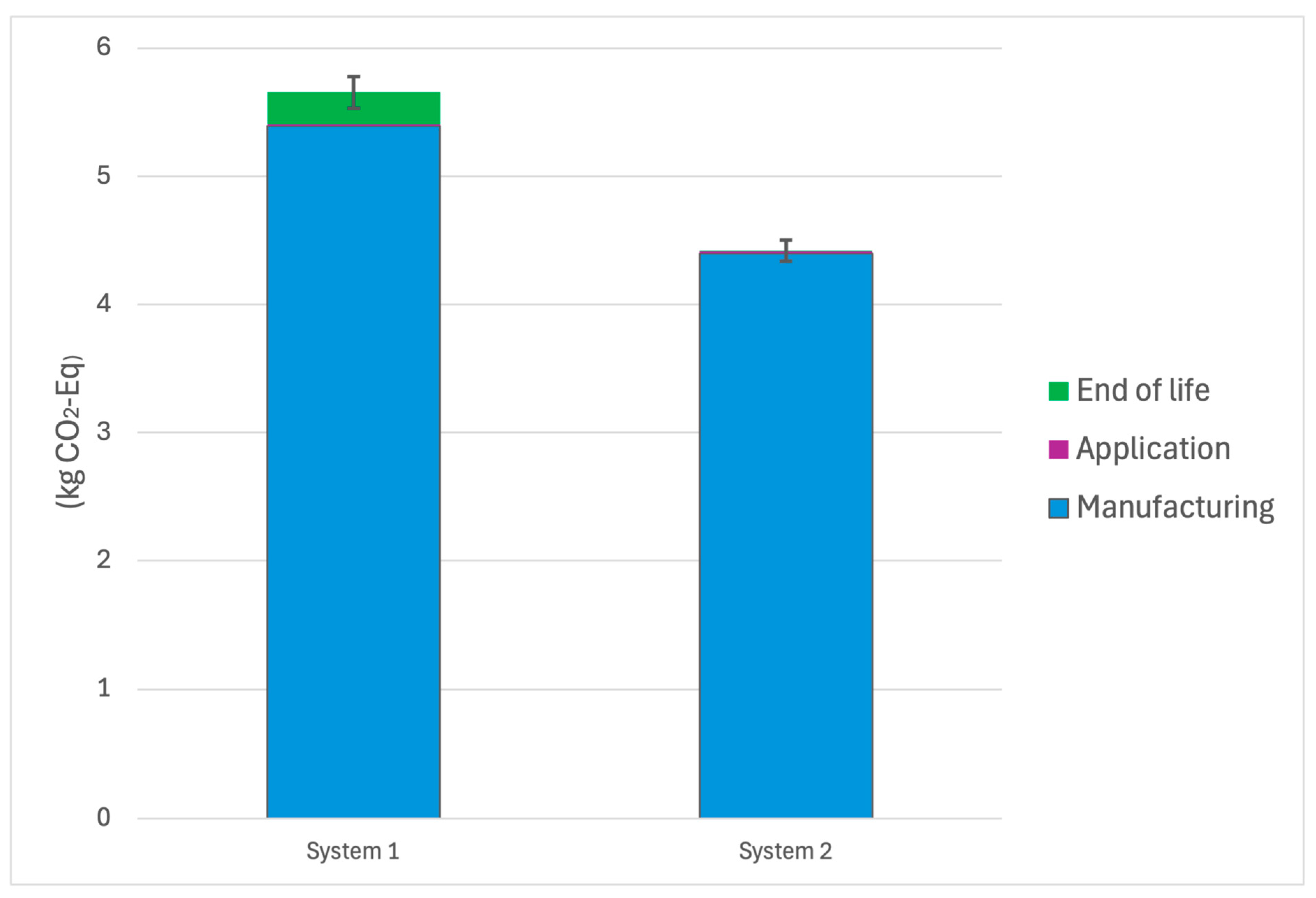
3.1. Global Warming Potential
Figure 3 below shows the global warming potential for both System 1 and System 2, including the phases and their contribution to the total GWP. As expected, the GWP was most highly contributed to by the manufacturing phase of both systems, heavily influenced by the processing and electro-refining of copper during copper oxide production.
System 2 demonstrated a 21.8% reduction in GWP compared to System 1 (4.42 vs. 5.65 kg CO2-eq per m2 over 5 years). In System 1, GWP was driven by the energy-intensive production of the Cu2O coating (4.37 kg CO2-eq) and the primer layer (0.62 kg CO2-eq). Additionally, even minor processes such as paint disposal and transport added measurable burdens.
By contrast, System 2’s embedded design simplified application and eliminated the need for multilayer coatings, resulting in a leaner energy profile during application (0.013 kg CO
2-eq) and more favorable end-of-life characteristics (−0.23 kg CO
2-eq), the latter due partially to no paint waste disposal and the recyclability of Cu
2O and polyethylene content. The negative GWP value in the disposal phase of System 2 reflects modeled carbon offsets through copper recovery and reduced landfill volume [
11].
These findings underscore that integrated antifouling systems not only streamline the installation process but also significantly reduce atmospheric emissions associated with traditional coating workflows.
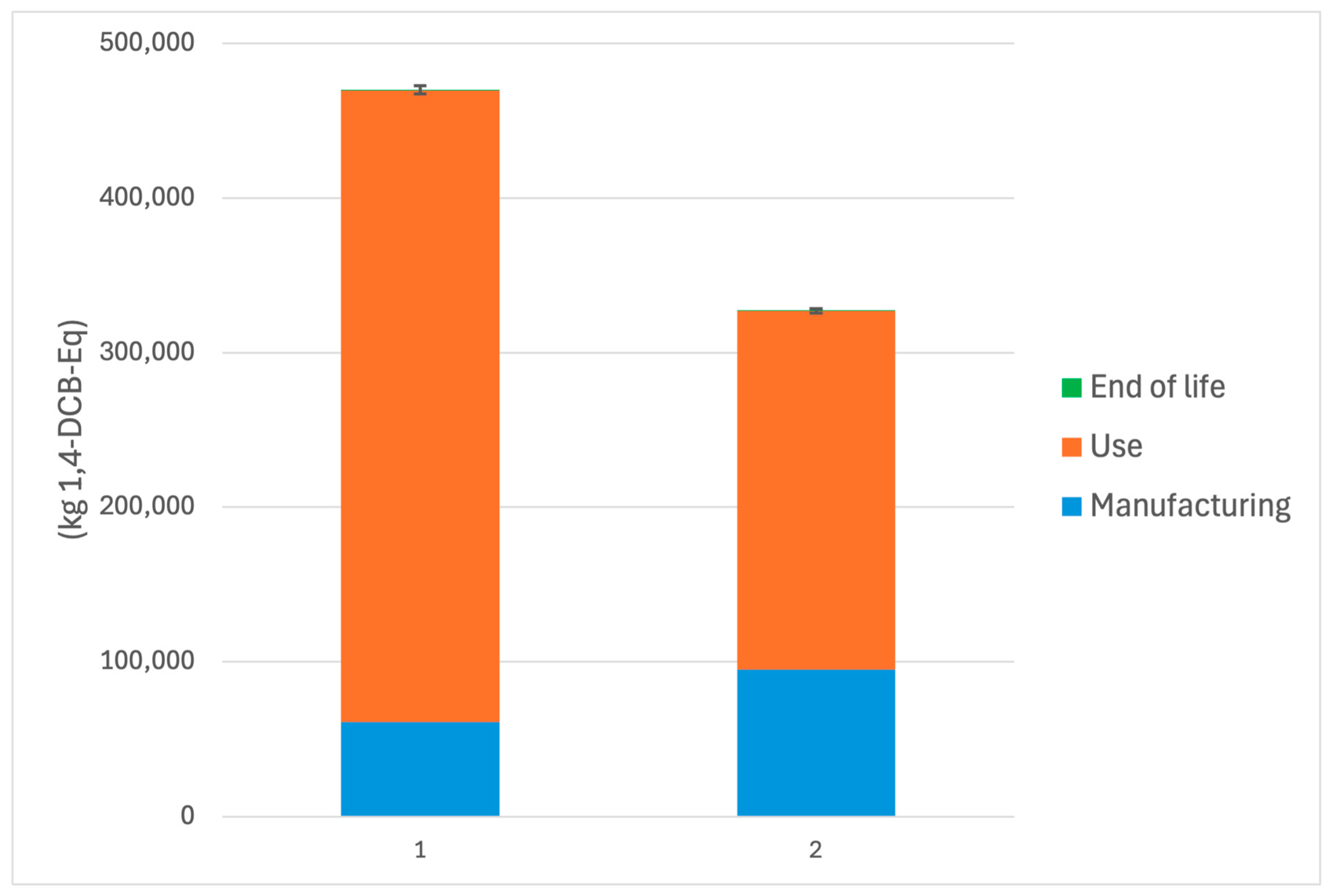
3.2. Marine Aquatic Ecotoxicity Potential
Marine aquatic ecotoxicity potential results illustrate the most dramatic difference between systems (
Figure 4). System 1 emitted a total of 469,929 kg 1,4-dichlorobenzene (DCB)-eq, compared to the 30.4% reduction to 327,002 kg 1,4-DCB-eq for System 2. The overwhelming contribution to MAETP in both systems occurred during the use phase—predominantly through the leaching of copper ions into marine environments. System 1 released an estimated 0.264 kg of Cu
2O over the functional lifespan, almost double the leach mass estimated for System 2 (0.149 kg).
Notably, System 1 also introduced VOC emissions (0.152 kg per m
2) during application, contributing to additional marine toxicity during air-to-water transfer. Moreover, the use of solvent-based coatings in System 1 increases indirect exposure pathways through runoff and atmospheric deposition [
12].
Although System 2 still contributes to MAETP via embedded Cu
2O diffusion, its encapsulation within the polymer matrix significantly delays and limits bioavailability [
5]. These outcomes are consistent with earlier studies identifying binder and matrix design as major variables influencing long-term leach rates and aquatic ecotoxicity [
6,
11].
3.3. Cumulative Energy Demand
Cumulative Energy Demand analysis revealed that System 2 required 75.3 MJ-eq over its lifecycle, compared to 91.0 MJ-eq for System 1, showing a 17.3% reduction in non-renewable energy consumption. As with GWP, the majority of CED in System 1 stemmed from the energy requirements of Cu2O coating production and primer application.
As shown in
Figure 5, System 2’s relatively low energy profile is attributed to the consolidated manufacturing process enabled by rotational molding, which integrates antifouling functionality directly into the structure. This eliminates intermediate steps such as primer mixing, surface preparation, and layer curing. Furthermore, by incorporating recycled Cu
2O and HDPE (30% content), System 2 achieved further energy reductions during the raw material acquisition stage.
Notably, while CED and GWP are closely correlated, the magnitude of improvement in CED was more pronounced, suggesting a particularly strong benefit from process efficiency and supply chain simplification in the novel system.
Error and Sensitivity Analysis
The error bars on each column chart were derived from Monte Carlo simulations conducted within OpenLCA using the EcoInvent database. These simulations account for variability and uncertainty in input data by repeatedly sampling from probability distributions assigned to key parameters, such as emission factors, material quantities, and energy usage. After running 1000 iterations, the results yield a distribution of impact values for each system. The upper and lower bounds of the error bars correspond to the 2.5th and 97.5th percentiles of the Monte Carlo output.
Importantly, there is no overlap in the error bars between System 1 and System 2 across all three impact categories (GWP, MAETP, and CED), signifying a high confidence level in the observed differences and supporting the conclusion that System 2 consistently outperforms System 1 in terms of environmental impact as shown in
Table 3,
Table 4 and
Table 5 below.
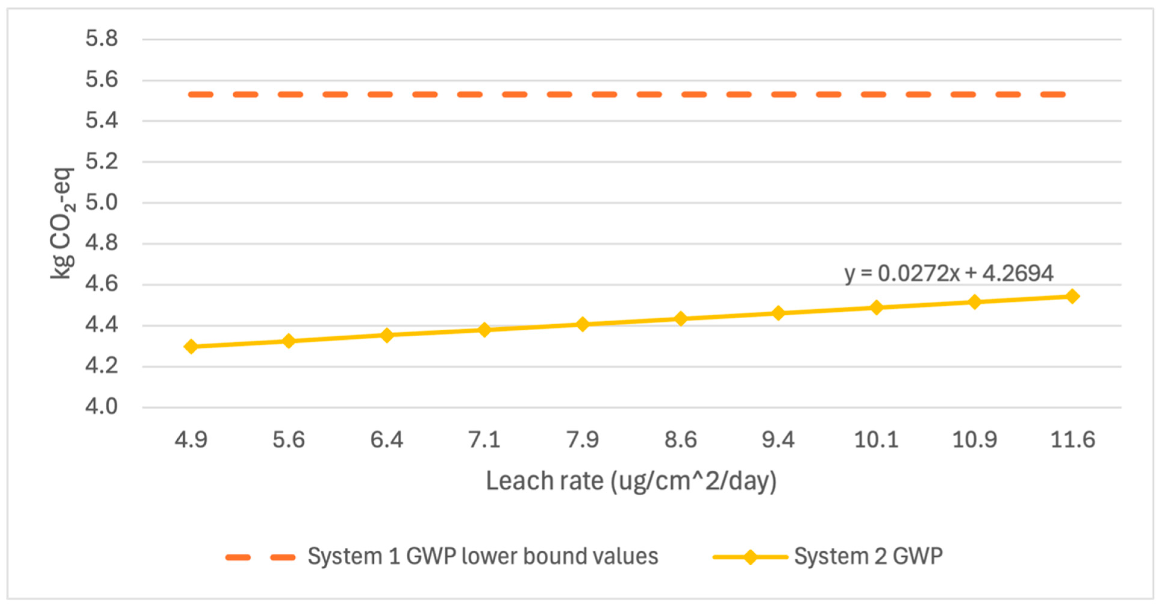
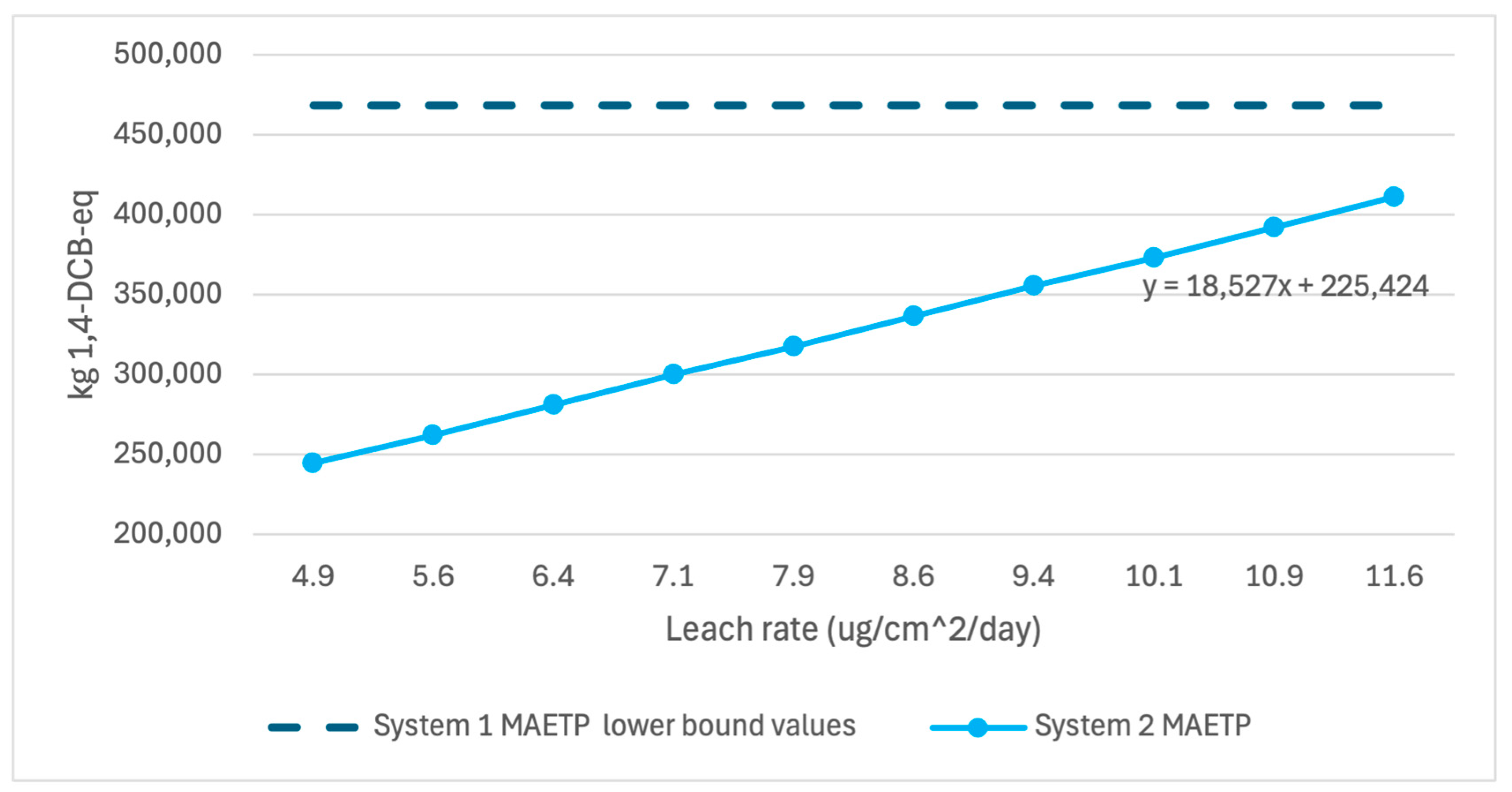
A sensitivity analysis was conducted to ensure the reliability of two key assumptions in the computation of System 2 results: leach rate and recyclability percentage. The leach rates pulled from the literature indicated a Cu
2O leach rate range of 4.85–11.5 micrograms/cm
2/day from polymer embedded systems [
12,
16,
17,
18].
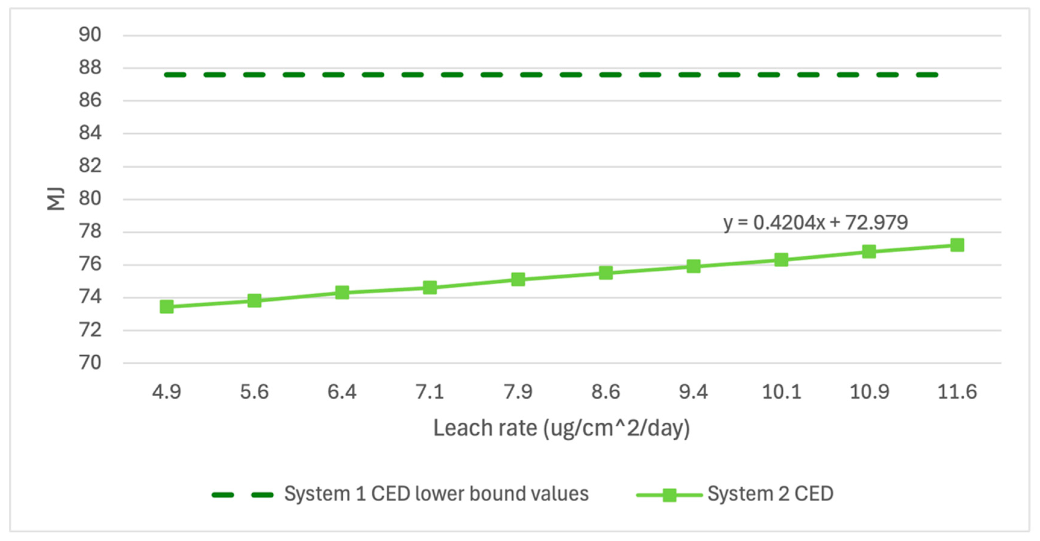
Figure 6,
Figure 7 and
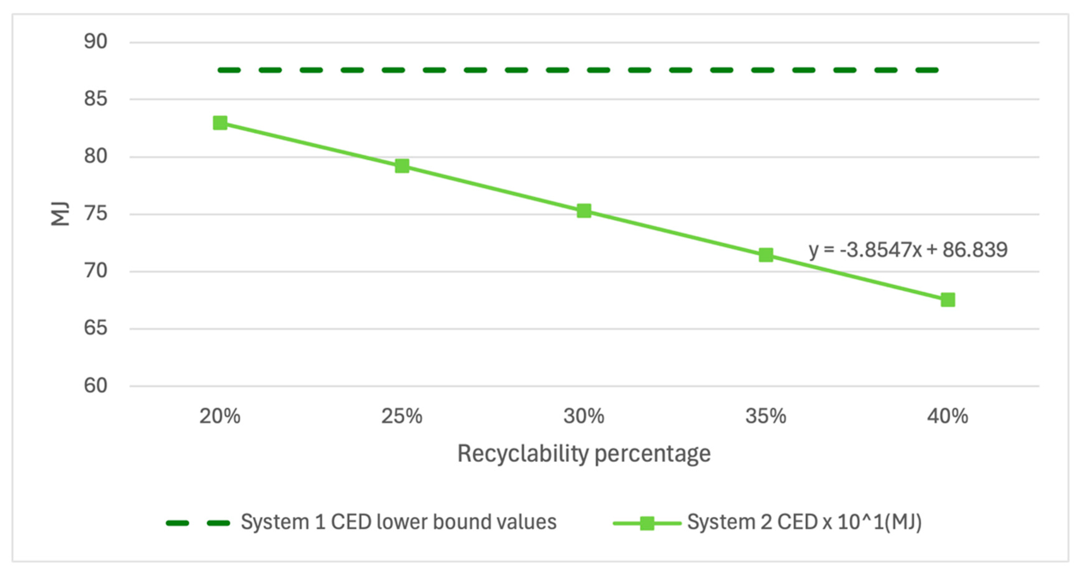
Figure 8 below show the variation in GWP, MAETP, and CED in System 2 over the range of published leach rate values compared to the lower bound values of System 1. System 2 GWP and CED results have low variability over the leach rate potentials, indicating little sensitivity to the selected leach rate. System 2 MAETP results showed much greater variability but still showed 14% lower MAETP values when unlikely high leach rate scenarios were examined.
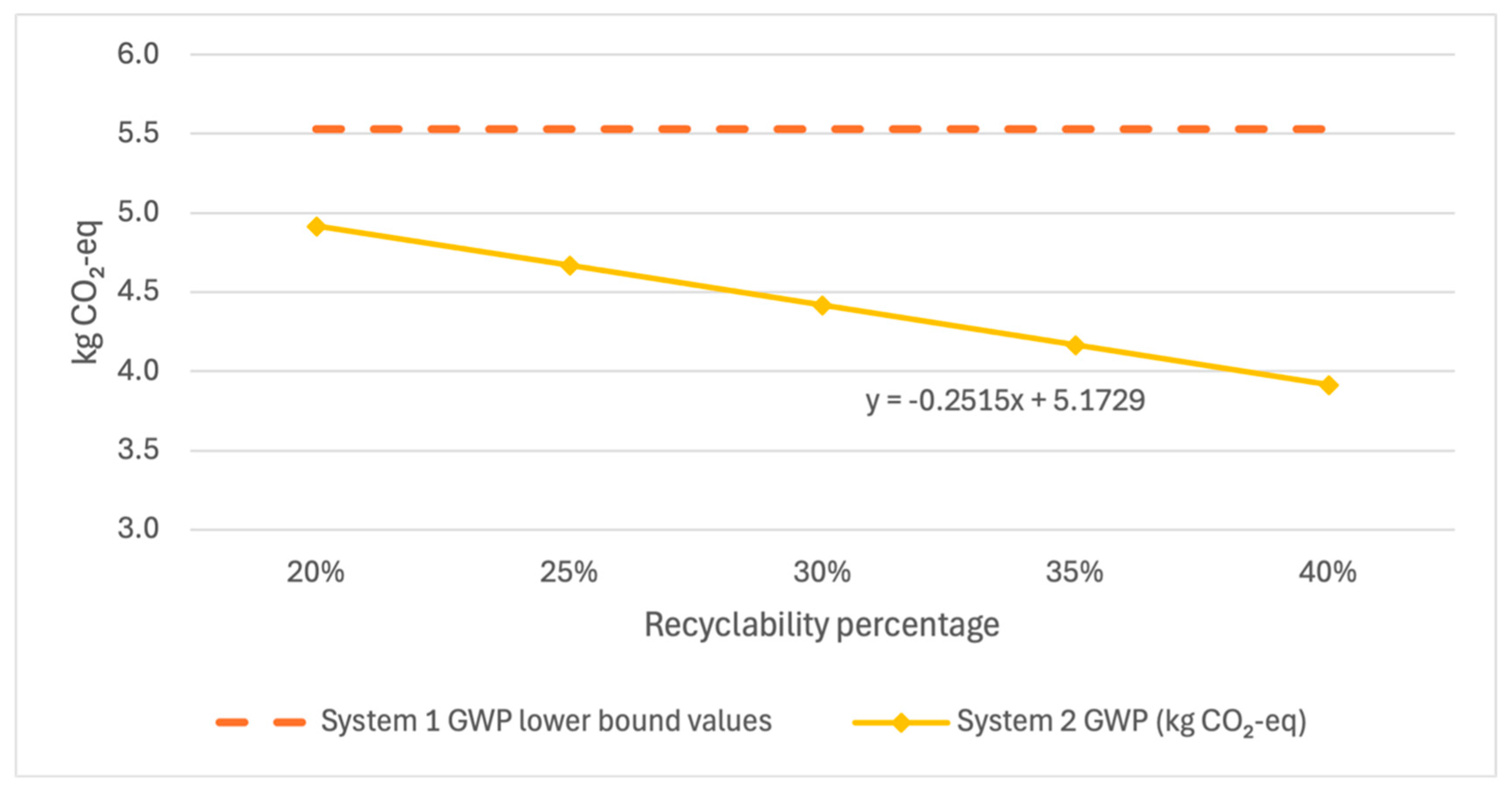
Additionally, a similar analysis was performed for the variability in recyclability of System 2 during the end-of-life phase. A case study and literature analysis indicate that recycled polyethylene embedded with Cu
2O particles may be combined with virgin polyethylene at between 25% and 35%.
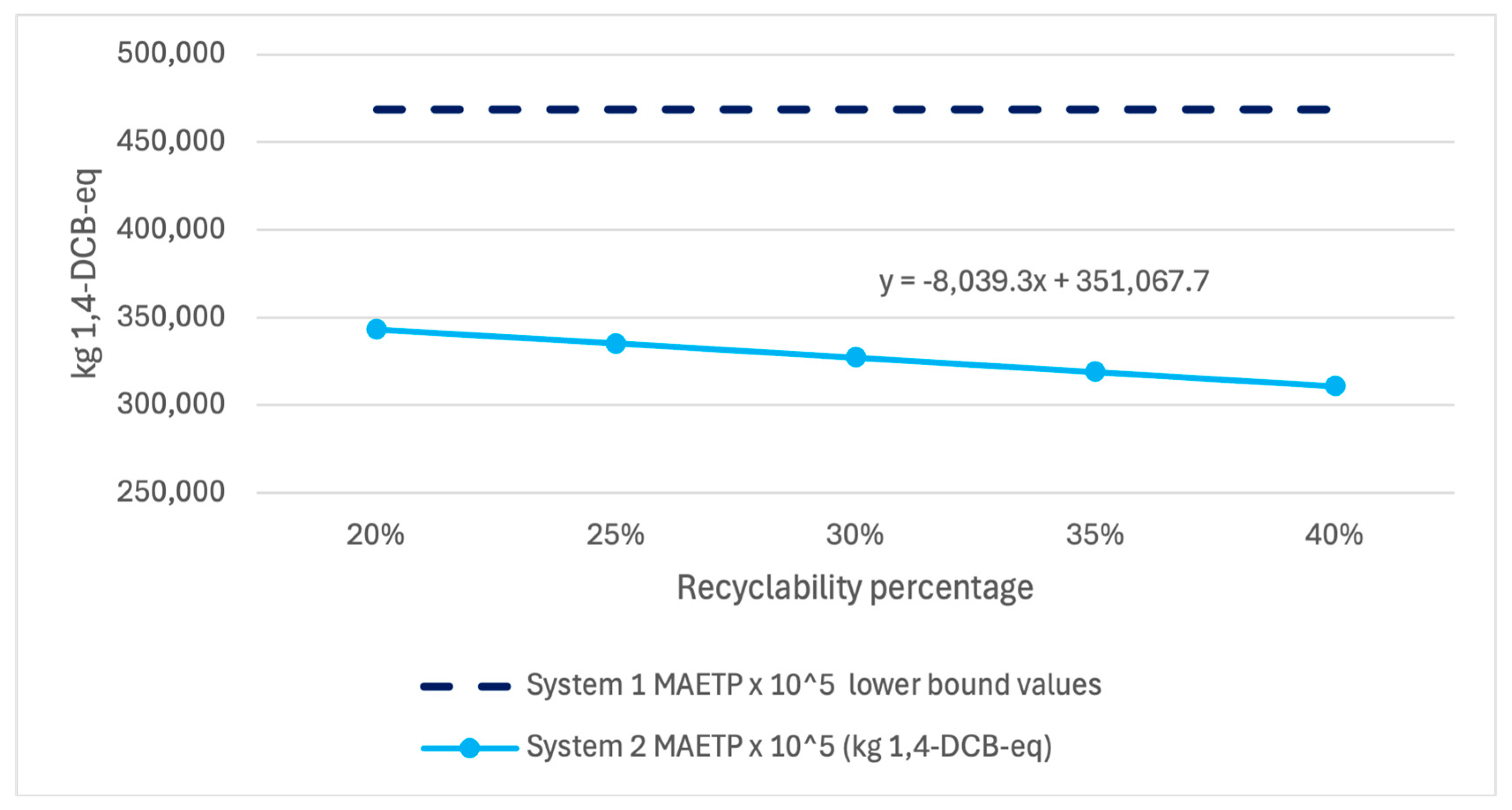
Figure 9,
Figure 10 and
Figure 11 show that System 2 results demonstrate little sensitivity to the selected 30% value when assessed using each impact metric and compared against the lower error bound of System 1, showing that no reasonable recyclability scenario would negate the findings of this study.
While System 2 MAETP results showed greater sensitivity to leach rate changes and CED and GWP results showed greater sensitivity to recyclability assumptions, each value fell well below the lower bound of error for System 1 values, indicating a high level of confidence in the given results within the published leach rate range.
3.4. Broader Implications
From a performance standpoint, both systems were assumed to offer equivalent antifouling efficacy over five years, a conservative estimate grounded in prior lab evaluations [
5,
22,
23,
24]. Thus, the environmental performance is the primary differentiator. The integrated System 2 presents significant advantages not only in environmental impact but also in logistical resilience, as it reduces material handling steps and potential failure points (e.g., chipping and delamination).
System 2 demonstrates better alignment with emerging sustainability priorities in marine infrastructure: reduced ecotoxicity, enhanced recyclability, and lower energy demand. These findings suggest that integrated antifouling materials offer a more sustainable and robust pathway for long-term deployment in marine environments. A direct comparison to recent LCA studies in antifouling coatings confirms the >20% reduction in GWP and >30% reduction found in this study, indicating a consistent decrease in these impact factors when embedded systems are utilized [
12,
14].
4. Conclusions and Future Work
Polymer-based marine structures, such as those made from high-density polyethylene (HDPE), are increasingly vital to offshore infrastructure but remain vulnerable to biofouling, which accelerates degradation, increases drag, and drives up maintenance costs. While copper-based biocidal coatings are traditionally used for protection, they pose challenges including application complexity, mechanical fragility, and environmental harm from VOCs and copper leaching.
Modeling approaches play a vital role in evaluating non-stationary or complex systems, as demonstrated in process-based simulations of gas regulation dynamics [
25]. In the context of life cycle modeling, such tools enable scenario testing across variable conditions. This study evaluates a more sustainable alternative: embedding Cu
2O directly into the polymer matrix. A cradle-to-grave LCA compared this embedded system (System 2) to a conventional coating system (System 1), focusing on global warming potential, cumulative energy demand, and marine aquatic ecotoxicity potential.
System 2 demonstrated substantial environmental benefits, with 21.8% lower GWP, 17.3% lower CED, and 30.4% lower MAETP. These gains are attributed to reduced material waste, lower leaching rates, and the elimination of primers and topcoats. The embedded approach also improved mechanical durability, potentially reducing the need for frequent reapplication.
These results position embedded Cu2O-HDPE composites as a more resilient and eco-friendly antifouling solution, particularly relevant for environments with strict discharge regulations. Future work should explore scaling, optimizing copper content, and validating long-term performance in field conditions.


