Article

Research on Synergistic Control Technology for Composite Roofs in Mining Roadways

1
School of Mining Engineering, Heilongjiang University of Science and Technology, Harbin 150022, China
2
Heilongjiang Longmei Jixi Mining Co., Ltd., Ronghua First Mine, Jixi 158100, China
3
Heilongjiang Longmei Shuangyashan Mining Co., Ltd., Shuangyashan 155100, China
*
Author to whom correspondence should be addressed.
Processes 2025, 13(8), 2342; https://doi.org/10.3390/pr13082342
Submission received: 17 June 2025 / Revised: 14 July 2025 / Accepted: 21 July 2025 / Published: 23 July 2025

Abstract

Addressing the stability control challenges of roadways with composite roofs in the No. 34 coal seam of Donghai Mine under high-strength mining conditions, this study employed integrated methodologies including laboratory experiments, numerical modeling, and field trials. It investigated the mechanical response characteristics of the composite roof and developed a synergistic control system, validated through industrial application. Key findings indicate significant differences in mechanical behavior and failure mechanisms between individual rock specimens and composite rock masses. A theoretical “elastic-plastic-fractured” zoning model for the composite roof was established based on the theory of surrounding rock deterioration, elucidating the mechanical mechanism where the cohesive strength of hard rock governs the load-bearing capacity of the outer shell, while the cohesive strength of soft rock controls plastic flow. The influence of in situ stress and support resistance on the evolution of the surrounding rock zone radii was quantitatively determined. The FLAC3D strain-softening model accurately simulated the post-peak behavior of the surrounding rock. Analysis demonstrated specific inherent patterns in the magnitude, ratio, and orientation of principal stresses within the composite roof under mining influence. A high differential stress zone (σ1/σ3 = 6–7) formed within 20 m of the working face, accompanied by a deflection of the maximum principal stress direction by 53, triggering the expansion of a butterfly-shaped plastic zone. Based on these insights, we proposed and implemented a synergistic control system integrating high-pressure grouting, pre-stressed cables, and energy-absorbing bolts. Field tests demonstrated significant improvements: roof-to-floor convergence reduced by 48.4%, rib-to-rib convergence decreased by 39.3%, microseismic events declined by 61%, and the self-stabilization period of the surrounding rock shortened by 11%. Consequently, this research establishes a holistic “theoretical modeling-evolution diagnosis-synergistic control” solution chain, providing a validated theoretical foundation and engineering paradigm for composite roof support design.

1. Introduction

Coal remains strategically irreplaceable in the contemporary global energy system as one of the world’s primary energy sources [1]. However, with the continuous increase in mining depth, stability control of surrounding rock in extraction roadways has become a critical challenge constraining safe and efficient coal production [2,3,4,5].
Composite roof strata—the primary target for roadway roof control—exhibit increasing internal heterogeneity that complicates control measures [6,7,8,9]. These roofs typically comprise thin to medium-thick strata of markedly different lithologies (e.g., mudstone, sandy mudstone, coal seams, thin sandstone) with divergent strength, elastic modulus, Poisson’s ratio, and brittleness/ductility characteristics. Significant disparities in physico-mechanical properties and deformation behavior among layers, particularly weak interlayers, induce pronounced interlayer incoordination during stress transfer [10,11,12,13,14]. This incoherence severely compromises the roof’s integrity and load-bearing capacity, becoming a key intrinsic factor triggering stratified failure, bed separation propagation, and ultimately zoned fracture structures. Consequently, heterogeneous stress distributions develop across composite roof layers [15].
Intense dynamic disturbances from mining activities constitute the dominant external driver for progressive roof deterioration [16,17]. As the working face advances, front abutment pressure peaks at 2–3 times the in situ stress. This high stress transmits pulse-like and incremental loads to the roof, cyclically loading composite strata near limit equilibrium. Shock effects from roof fracturing and transient dynamic loads from adjacent stopes or fault activation directly trigger local instabilities or accelerate zoned fracture propagation [18,19,20].
Grouting reinforcement and bolt/cable support are core technologies for roadway roof control. Grouting reinforcement [21]: It fills rock fractures, cements fragmented surrounding rock, and enhances mechanical properties. It significantly increases rock density and uniaxial compressive strength while improving cohesion and internal friction angle of fractured rock masses. Bolt/cable support [22]: Prestressed anchor cables provide active support via tensile constraints to balance rock mass shear forces. Constant-resistance energy-absorbing bolts (yield strength: 906.9 MPa, elongation: 26.5%, energy absorption efficiency ≥ 3× conventional bolts) utilize microstructural material design for efficient energy dissipation [23].
The aforementioned research holds significant implications for controlling composite strata in deep mining gateways. However, three critical aspects warrant further investigation:
Traditional Mohr–Coulomb models, based on homogeneous continuous medium assumptions, neglect the alternating distribution of weak interlayers and hard rock strata in laminated composite roofs. This stratification disrupts stress transfer continuity, impeding the formation of synergistic load-bearing structures through bolt support [24,25]. Mining-induced deflection of principal stress orientations triggers asymmetric expansion of butterfly-shaped plastic zones. Conventional models fail to characterize the coupling between principal stress directionality and plastic zone morphology, leading to substantial errors in predicting anchorage failure locations of cable bolts—particularly when “butterfly lobes” rotate above the roof, completely enveloping anchorages within plastic zones [26]. While existing stability control schemes account for mining disturbances, they primarily focus on stress magnitude increases, paying insufficient attention to the full-lifecycle dynamic evolution of principal stress directions in gateways [27].
This study, grounded in the engineering context of gateway stability in Heilongjiang’s deep mining areas, proposes a differentiated synergistic support scheme through field investigations and laboratory mechanical tests. Industrial trials validated its efficacy, providing comprehensive theoretical-practical analysis of surrounding rock stability and actionable support optimization strategies. The outcomes deliver both theoretical foundations and technical guidance for support design in Heilongjiang’s deep mines, while offering referential value for mining projects under analogous geological conditions.

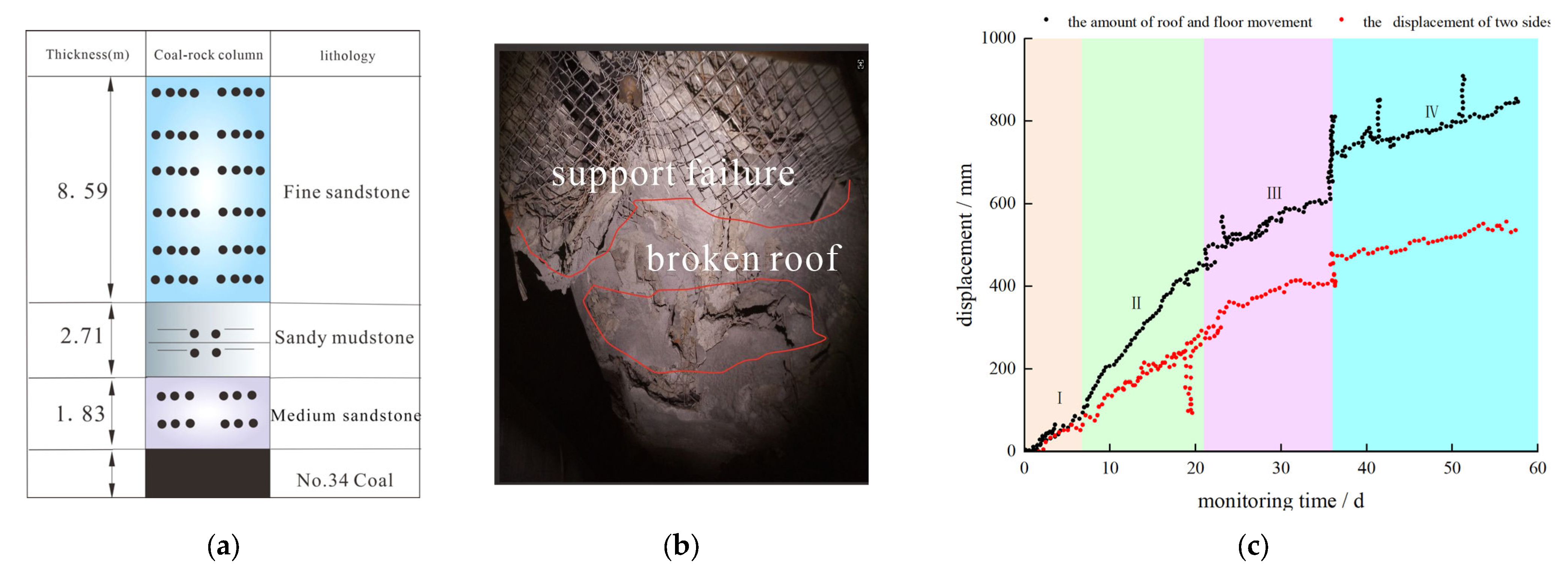
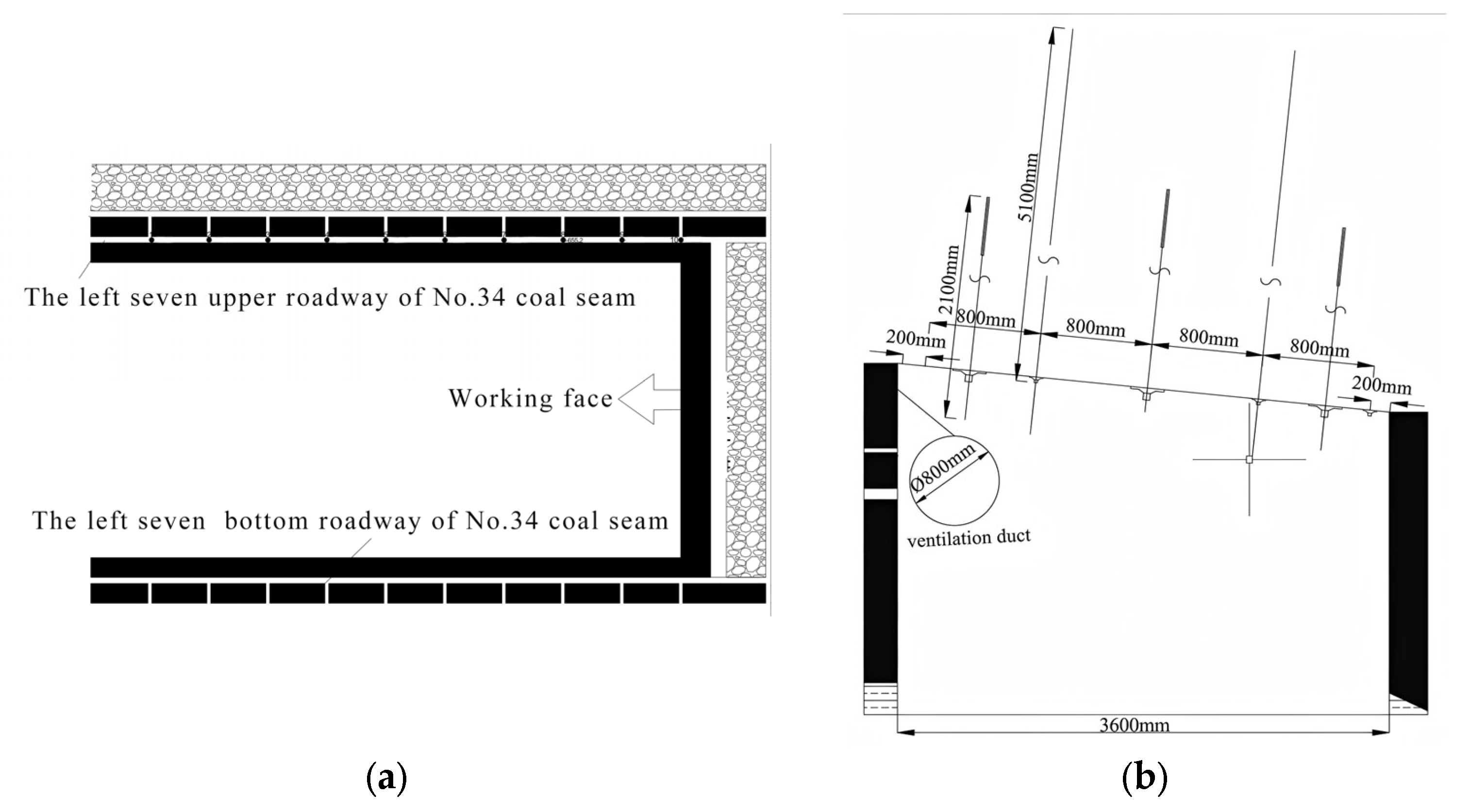
2. Engineering Background

The left seventh roadway in the No. 34 coal seam of the Donghai Coal Mine, Jixi Mining Area, serves as a typical case study of composite roof conditions. This roadway is located at a depth of 800 m. Within the support control zone, the composite roof comprises three distinct layers: 1.83 m fine sandstone, 2.71 m sandy mudstone, and 8.59 m medium sandstone (Figure 1a).
As illustrated in Figure 1b, field monitoring data reveals significant stability challenges associated with conventional support methods. Under the traditional bolt–cable support system, roof convergence deformation reached 955 mm. The monitoring results demonstrate severe distortion of the roadway surface under the original support scheme. The deformation process comprises four distinct stages: rapid deformation (0–8 days), accelerated deformation (8–21 days), slow deformation (21–45 days), and stabilized deformation (beyond 45 days), as shown in Figure 1c. These deformation magnitudes exceed the tolerable threshold for safe mining operations, rendering the system incapable of meeting daily production requirements.
As shown in Figure 2a,b, a combined bolting–cable support system is employed. The rock bolts consist of φ20 mm threaded steel bars with a length of 2.1 m, installed at a spacing of 1.1 m (row spacing) × 0.95 m (bolt spacing). The cables are φ21.8 mm steel strands, with a length of 5.1 m, installed at a spacing of 1.6 m × 1.0 m.

3. Physical and Mechanical Testing of Compound Roof Strata

Based on the comprehensive stratigraphic column for No. 34 coal seam, rock sampling was conducted in the compound roof strata area of the Left 7th working face within the No. 34 coal seam of the Donghai Coal Mine. In the tests, samples of fine sandstone were designated as A, medium sandstone as B, and sandy mudstone as C. The collected rock samples underwent standard procedures including transport, specimen processing, molding, and assembly (Figure 3) Subsequently, the specimens were prepared according to testing standards, resulting in composite strata specimens for surrounding rock analysis.
The design scheme for the rock mass composite specimen is delineated as follows: The specimen exhibits overall dimensions of a height of 100 mm and a diameter of 50 mm. The thicknesses of the constituent layers—fine sandstone, medium sandstone, and sandy mudstone—are specified as 30 mm, 40 mm, and 30 mm, respectively, meticulously assembled to emulate the on-site composite roof structure.
For layer bonding, marble adhesive is utilized, renowned for its superior bonding strength and rapid curing properties. This adhesive achieves a bonding strength ranging from 7 to 12 MPa, with the capability to withstand compressive shear forces between 10 and 35 kN. Such characteristics enable effective maintenance of structural integrity when bonding soft and hard composite rock masses. Furthermore, the high toughness inherent in the marble adhesive significantly reduces the risk of interface peeling, ensuring that failure occurs within the rock mass itself rather than within the adhesive layer. The meticulous preparation of the soft and hard composite rock masses guarantees the vertical alignment of the bedrock, thereby satisfying essential mechanical performance criteria.

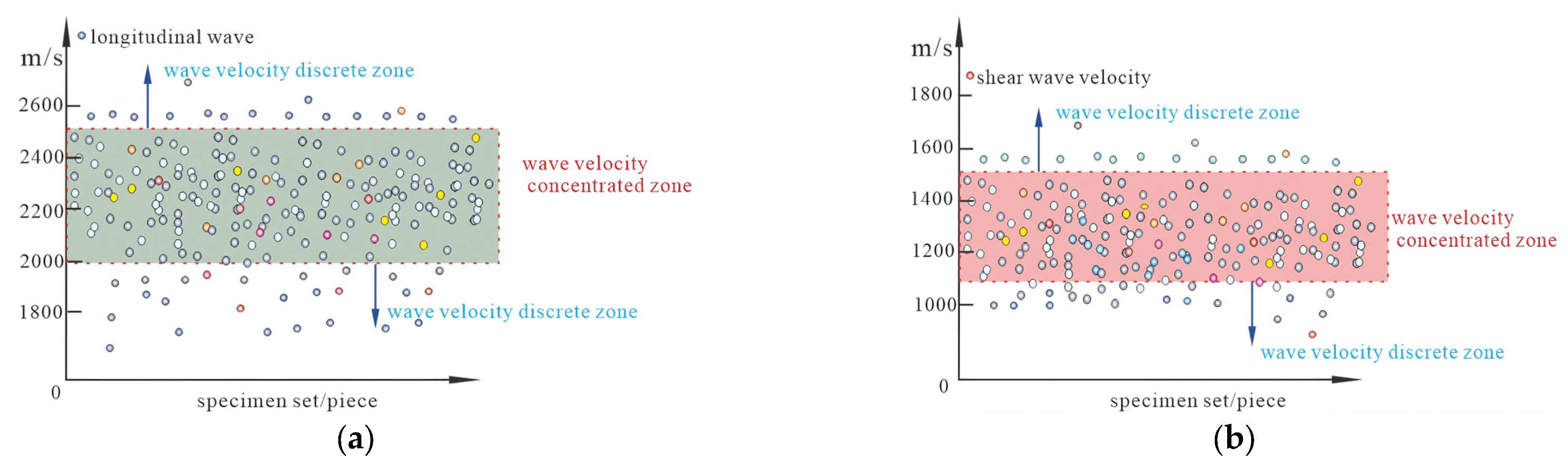
3.1. Mechanical Testing Scheme for Composite Surrounding Rock Specimens

The experiment employed a uniaxial compression loading method with a loading rate of 0.5 MPa/s. Throughout the loading process, real-time monitoring of the stress–strain curve was conducted, and deformation/failure characteristics were recorded. Upon reaching the peak strength, loading continued until specimens underwent complete instability and structural failure.
Based on the acoustic wave testing results of the composite surrounding rock specimens shown in Figure 4, specimens were screened according to wave velocity to exclude the influence of specimen discreteness. Over 96% of the specimens exhibited P-wave velocities between 2000 and 2500 m/s and S-wave velocities between 1050 and 1500 m/s. Specimens with wave velocities significantly deviating from this primary distribution range were excluded to ensure that experimental results accurately reflect the mechanical properties of the composite surrounding rock and reduce errors.

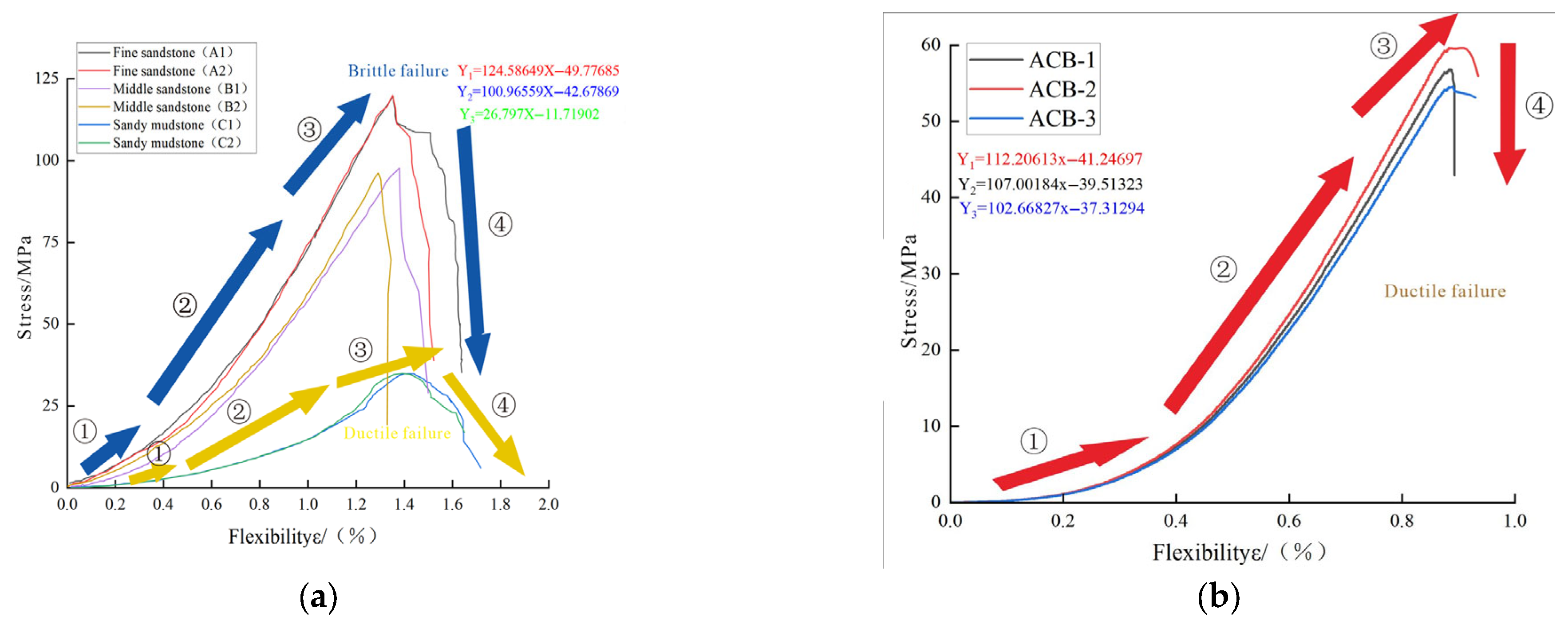
3.2. Analysis of Mechanical Properties of Surrounding Rock Composite

Tests were conducted on both monolithic specimens and composite specimens of surrounding rock. The mechanical parameters of monolithic specimens are listed in Table 1, providing key inputs for subsequent numerical simulations.
Mechanical tests were performed on both monolithic and composite surrounding rock specimens. The peak strengths of monolithic specimens were 120.19 MPa for fine sandstone showing brittle failure, 97.60 MPa for medium sandstone showing brittle failure, and 35.14 MPa for sandy mudstone showing ductile failure. In contrast, the composite specimen exhibited an average peak strength of 56.67 MPa, representing a 52.85% reduction compared to fine sandstone, a 41.94% reduction compared to medium sandstone, and a 61.27% increase compared to sandy mudstone.
As shown in Figure 5, both specimen types progressed through four deformation stages: ① compaction stage, ② elastic stage, ③ plastic stage, and ④ post-peak stage. The composite specimen demonstrated ductile failure characteristics controlled primarily by the central sandy mudstone layer. These results indicate that stability control techniques for composite roof strata must account for mechanical disparities between interbedded rock layers.
Brazilian tensile tests and direct shear tests were conducted to obtain critical parameters including compressive strength, tensile strength, cohesion, and internal friction angle, as documented in Table 1.

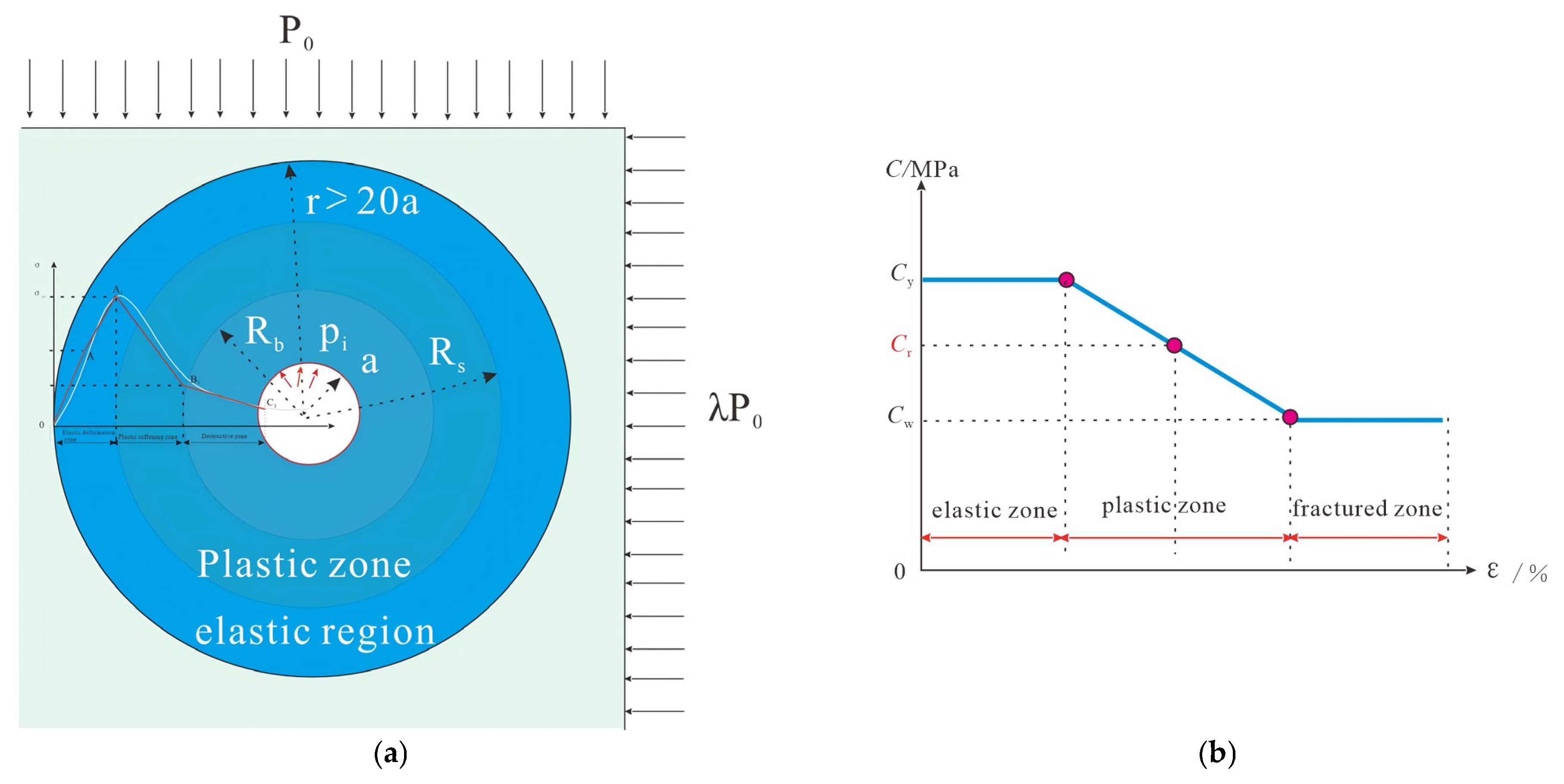
4. Research on the Theoretical Model of Zoning Deterioration in Surrounding Rock

Traditional theories struggle to accurately describe the nonlinear response characteristics of mining roadway surrounding rock under stress disturbances. To overcome these limitations, relevant studies propose a zoning fracturing model for the surrounding rock. This model, based on stress redistribution induced by roadway excavation, divides the surrounding rock into three distinct zones:
Elastic Zone: Serves as the core load-bearing structure, primarily responsible for transferring initial stresses.
Plastic Zone: Acts as a stress adjustment belt, mitigating localized stress concentrations through redistribution.
Fractured Zone: Represents a load-bearing failure region, marking the onset of surrounding rock instability.
The division into these three zones—elastic–plastic–fractured—forms a unique triple-zone evolution characteristic. The elastic zone functions as the primary stress-transfer mechanism; the plastic zone accommodates stress adjustments to alleviate concentration; and the fractured zone signifies structural failure initiation.
By introducing the zoning deterioration theory, a comprehensive description of the coupling interactions between composite roof and surrounding rock is achieved. This approach provides a robust theoretical basis and technical support for roadway support design.

4.1. Zonal Deterioration Theoretical Model

The zonal deterioration theoretical model (Figure 6a,b) for surrounding rock integrates classical elastic–plastic theory and employs mathematical limit analysis. By incorporating the stress continuity condition and the plastic softening condition (Equation (1)) into the Mohr–Coulomb criterion (Equation (2)), the model ultimately solves the differential equation to derive the mechanical equilibrium equations for the elastic zone, plastic zone, and fractured zone. This analysis, based on the constitutive relationships between stress and strain during rock deterioration and the equilibrium differential equations, enables the derivation of the stress and strain distribution characteristics within the surrounding rock and the solution for the radii of the plastic and fractured zones. It is assumed that stress continuity conditions exist between the elastic zone, plastic zone, and fractured zone; that is, stresses satisfy continuity requirements at their interfaces. This is equivalent to consistent radial and tangential stresses at the interface between the plastic zone and the elastic zone, providing boundary conditions for the solution.
The plastic softening condition formula (Equation (1)) describes the dynamic deterioration law of material strength parameters with the accumulation of plastic strain. It reveals the inhomogeneous softening characteristics arising from lithological differences within composite roof strata during loading. Based on the Mohr–Coulomb criterion as the fundamental strength criterion, this model controls the gradient-dependent deterioration of strength parameters for different rock layers through weakening parameters, thereby accurately characterizing the mechanical response differences in various rock strata at different deformation stages.
Compared to traditional elastic-plastic models, the nonlinear softening model integrated with the unified strength theory offers significant advantages. Firstly, it employs piecewise linear functions to simulate the nonlinear deterioration relationship between strength parameters and plastic strain. Secondly, it modulates the effect of the intermediate principal stress through coefficients. This combination more realistically reflects the regulatory effect of interlayer mechanical property differences within composite roof strata on the extents of the elastic zone, plastic zone, and fractured zone.
C s = C 0 M c ε θ s ε θ r = R s M c = C y C r ε θ r = R b ε θ r = R s
σ θ = A σ r + C K φ
A = 1 + sin φ 1 sin φ ; K φ = 2 cos φ 1 sin φ
In the formula:
Cs is the softened cohesion, which is consistent with the mechanical properties of rock masses after softening (MPa);
Cy and Cr represent the cohesion of soft rock and hard rock in composite rock mass, respectively, with different characteristics of composite rock mass;
εθs is the tangential strain of any mass point in the plastic softening zone;
εθ/r = RS is the tangential strain at the outer boundary of the plastic softening zone;
εθ/r = Rb is the tangential strain at the outer boundary of the fracture zone;
Mc is the softening modulus;
φ is the internal friction angle (°);
C0 is the cohesive force (MPa);
A is a function of the internal friction angle φ, and it is always greater than 1.
kΦ is a coefficient reflecting the cohesive strength characteristics of a material, which is related to the cohesive force C.
The mechanical analysis of the elastic zone, centered on the thick-walled cylinder model, integrates boundary conditions and material parameters to comprehensively characterize the distribution patterns of stress, strain, and displacement fields. This framework constitutes the foundational basis for deriving the zoned deterioration model of surrounding rock.
By isolating the elastic unit from the zoned mechanical model of surrounding rock, the elastic zone is abstracted as an annular region with an inner radius Rs.
With in the elastic zone, the following relationships govern the mechanical response (radius of the plastic-softening interface) and an infinitely large outer radius. Its mechanical behavior is analytically resolved using the principles of elasticity.
The following mechanical relationships apply within the elastic zone:
σ r e = P 0 1 R s 2 r 2 + σ r r = R s R s 2 r 2 σ θ e = P 0 1 + R s 2 r 2 σ r r = R s R s 2 r 2
u e = 1 + μ E ( P 0 σ r r R ) R s 2 r ε r e = 1 + μ E P 0 σ r r = R s R s 2 r 2 ε θ e = 1 + μ E P 0 σ r r = R s R s 2 r 2
In the formula:
σre is the radial stress in the elastic zone;
σθe is the tangential stress in the elastic zone;
μe is the surface displacement of the elastic zone roadway;
εθe is the tangential strain in the elastic zone;
εre is the elastic zone diameter;
P0 is the stress of the primary rock.
Based on the mechanical model of the plastic softening zone, the isolated analysis can be abstracted as an annular region with an inner radius Rb (fractured zone boundary) and an outer radius Rs (plastic-softening interface). The mechanical behavior of this zone is analytically resolved without considering support conditions, governed by the plastic softening criterion. The relationships governing the plastic softening zone are defined as follows:
σ r s = b 2 K φ 1 A b 3 K φ A + η s ( R s r ) η 1 + 1 + b 4 r A 1 σ θ s = A [ m n ( R s r ) η 1 + 1 + ( σ r r = R s m + n ) ( r R s ) A 1 ] + C s K φ
m = d 2 K φ 1 A = K φ 1 A [ C y + C y C r ( R s / R b ) η 1 + 1 1 ] n = d 3 K φ A + η 1 = K φ A + η 1 [ C y C r 1 ( R s / R b ) η 1 + 1 ]
ε r s = 1 + μ E ( P 0 σ r r R s ) [ η 1 1 η 1 + 1 2 η 1 η 1 + 1 ( R s r ) 1 η 1 ] ε θ s = 1 + μ E ( P 0 σ r r R s ) [ η 1 1 η 1 + 1 + 2 η 1 + 1 ( R s r ) 1 η 1 ]
In the formula:
σrs is the radial stress in the plastic zone;
σθs is the radial stress in the plastic zone
εθs is the tangential strain in the plastic zone;
εrs is the radial strain in the plastic zone;
η is the expansion coefficient;
b is an integral constant.
Based on the mechanical model of the fractured zone, the isolated analysis can be abstracted as an annular region with an inner radius equivalent to the tunnel radius and an outer radius equal to the fractured zone boundary Rs. The mechanical behavior of this zone is governed by the following relationships.
σ r s = a 2 K φ 1 A a 3 K φ A + η s ( R s r ) η 1 + 1 + a 4 r A 1 σ r b = C w K φ 1 A + ( P i C w K φ 1 A ) ( r a ) A 1 σ θ b = C w K φ 1 A + A ( P i C w K φ 1 A ) ( r a ) A 1
ε r b = 1 + μ E ( P 0 σ r r = R s ) η 2 [ η 1 1 η 1 + 1 + 2 η 1 + 1 ( R s R b ) 1 + η 1 ] ( R b r ) 1 + η 2 ε θ b = 1 + μ E ( P 0 σ r r = R s ) [ η 1 1 η 1 + 1 + 2 η s + 1 ( R s R b ) 1 + η 1 ] ( R b r ) 1 + η 2
In the formula:
σrb is the radial stress in the destructive zone;
σθb is the tangential stress in the destructive zone;
εθb is the tangential strain in the destructive zone;
εrb is the radial strain in the destructive zone;
a is an equivalent radius of the roadway.
Based on the continuity condition of radial stress at the interface between the fractured zone and the plastic zone, combined with elastoplastic theory and strength deterioration models of surrounding rock, the deterioration radii of the fractured zone (Rb) and the plastic zone (Rs) can be analytically derived as follows:
τ = R s R b = 1 η 1 1 + η 2 2 η 2 η 1 1 1 + η 1
R b = a m n τ η 1 + 1 + σ r r = R s m + n τ 1 A C w K φ / 1 A P i C w K φ / 1 A 1 A 1
R s = R b × τ = a 1 η 1 1 + η 2 2 η 2 η 1 1 1 + η 1 m n τ 1 + η 1 + σ r r = R s m + n τ 1 A C w K φ / 1 A P i C w K φ / 1 A 1 A 1
By using the above method, the stress distribution patterns of the elastic zone, plastic zone, and failure zone are derived. In the plastic zone, the combination of radial stress and tangential stress satisfies the Mohr–Coulomb criterion, and the interlayer difference characteristics of the composite roof are further calculated to determine the radius of the plastic zone. For the failure zone, the calculation of its radius depends on the strength parameters and stress redistribution of the surrounding rock after failure softening, and the changes in parameters directly affect the expansion range of the failure zone.

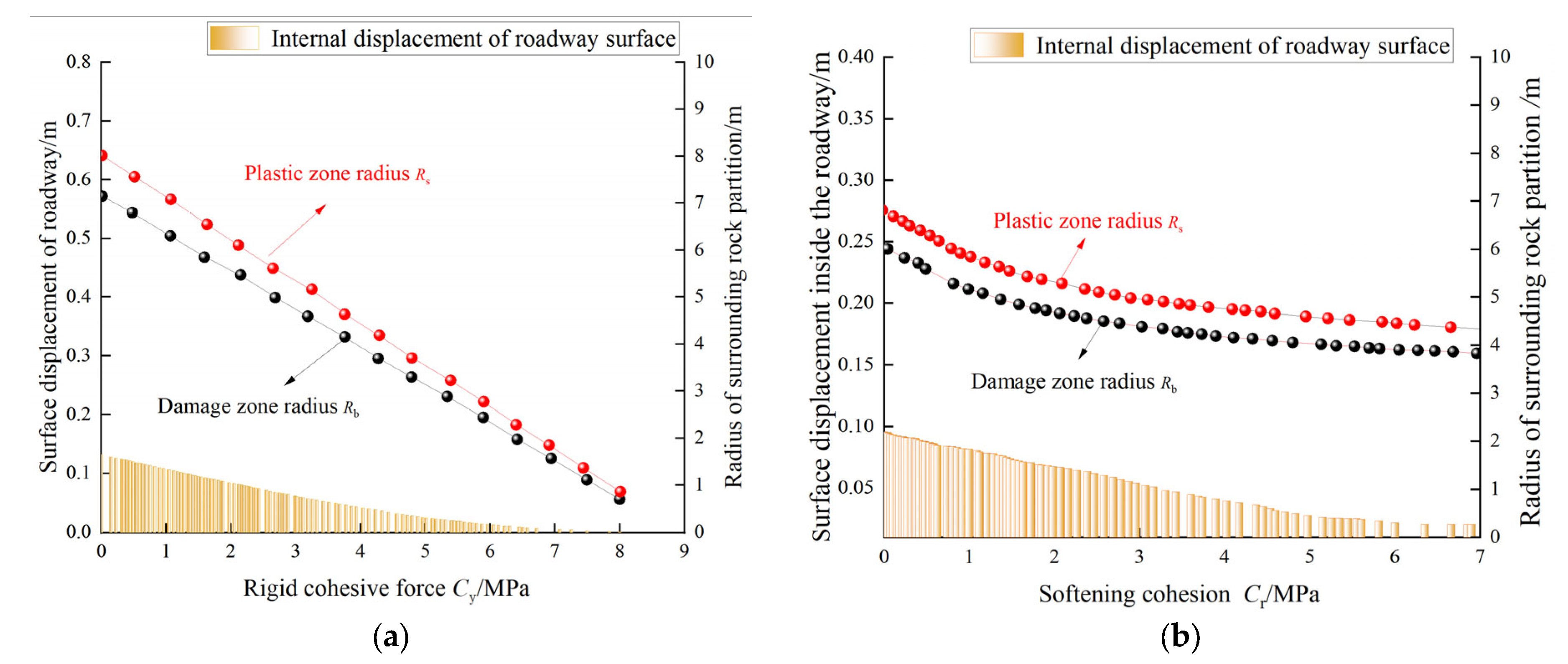
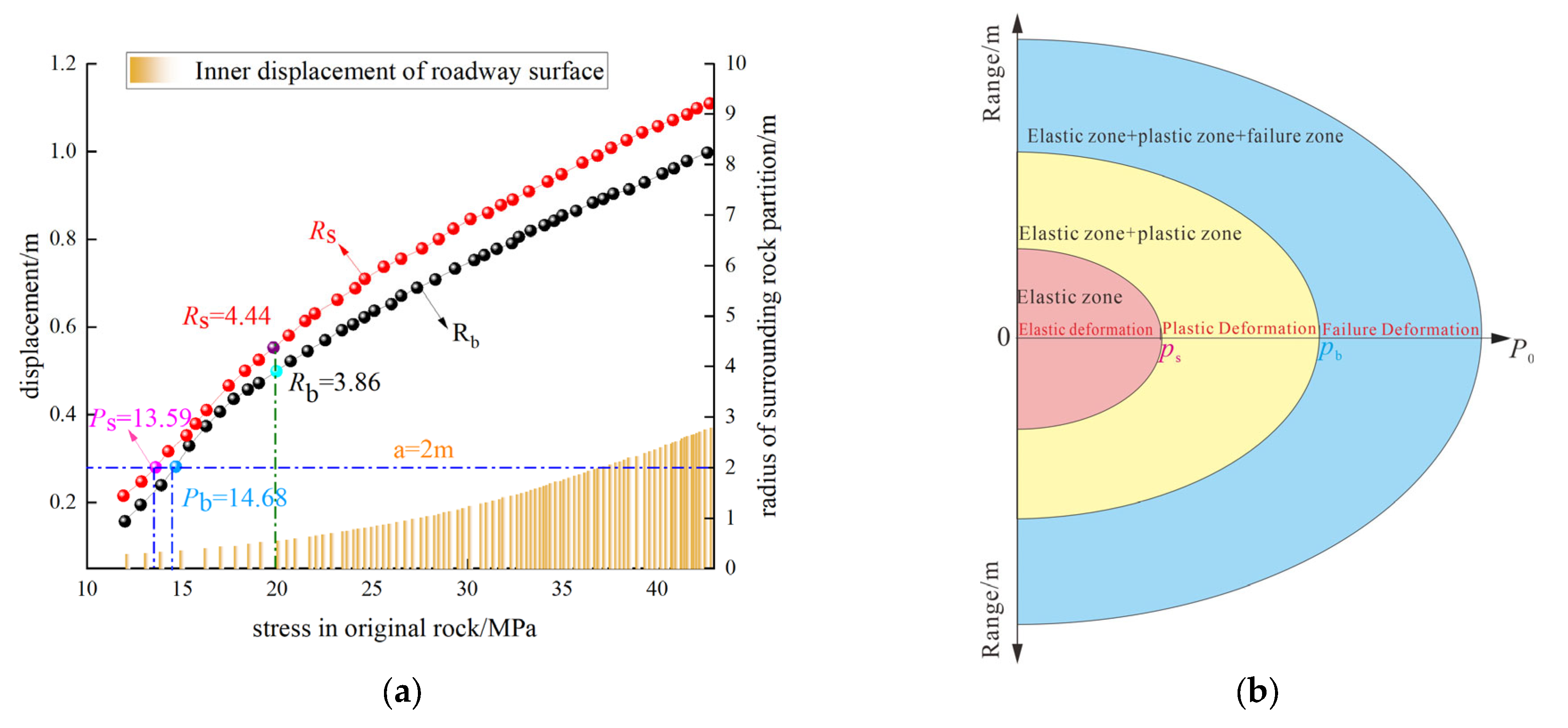
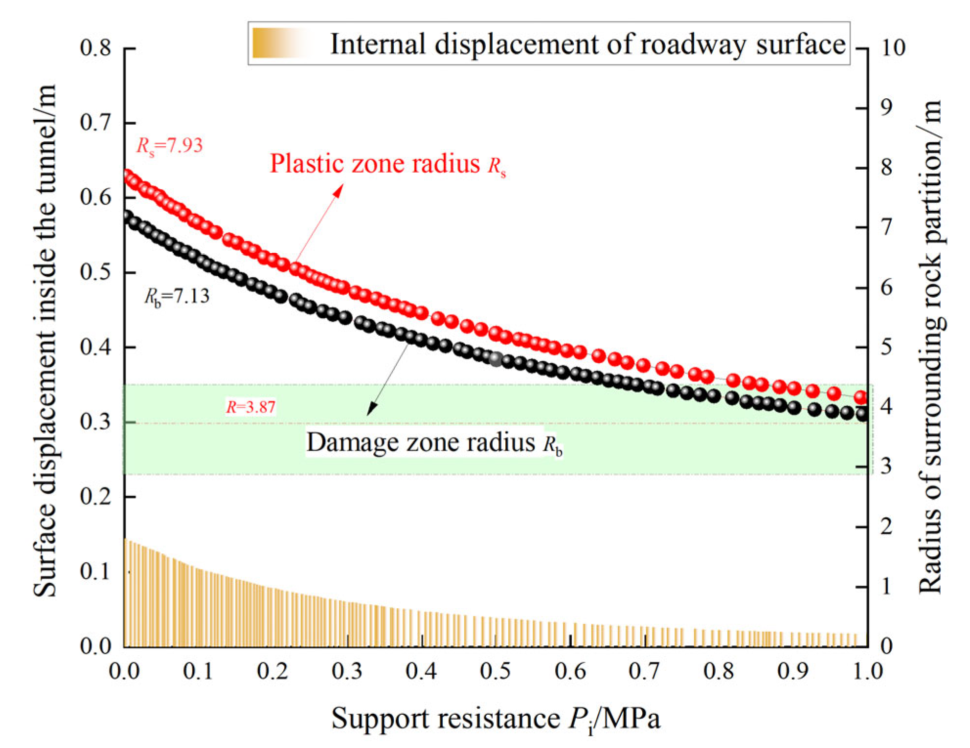
4.2. Analysis of Partition Response of Surrounding Rock in Mining Roadway

The average bulk density of the rock strata in the No. 34 coal seam of the Donghai Coal Mine is taken as 25 kN/m3. The burial depth of the coal seam is 800 m. This yields an in situ stress of 20 MPa. The dilation coefficient of the fractured zone is 1.4. The roadway radius is 2 m. The initial support resistance is 0.5 MPa. The elastic zone boundary is defined as 20 times the radius, i.e., areas beyond 40 m constitute the elastic zone. Theoretical analysis is conducted using these surrounding rock parameters.
Figure 7 illustrates the surrounding rock deterioration curve under boundary conditions of 20 MPa in situ stress and 0.5 MPa support resistance. The horizontal axis (x) denotes distance from the roadway boundary. The left vertical axis (y1) represents surface displacement deformation, while the right vertical axis (y2) indicates calculated stress values. The surrounding rock is divided into three zones radiating outward from the roadway surface: a 0–6 m fractured zone, a 6–8 m plastic zone, and an elastic zone beyond 8 m. Tangential stress (σθ) rises rapidly to its peak within the fractured zone, then gradually attenuates toward the in situ stress of 20 MPa. Radial stress (σr) increases slowly, converging to the in situ stress. The rate of change in the tangential stress significantly exceeds that of the radial stress. Stress discontinuities occur at the fractured–plastic (x = 6 m) and plastic–elastic (x = 8 m) interfaces, forming characteristic inflection points. These discontinuities originate from the theoretical model’s description of heterogeneous properties in composite roof strata, with abrupt changes localized at weak rock layer interfaces—high-risk areas for roof instability.
In the seventh left mining roadway of the No. 34 coal seam in the Donghai Coal Mine, the peak intensity and the stress gradient of the tangential stress (σθ) significantly surpass those of the radial stress (σr). This disparity suggests that roadway instability predominantly manifests as a composite shear-tensile failure, driven primarily by tangential deformation. Analysis of displacement reveals a maximum deformation of 0.57 m at the surface of the fractured zone, with displacement diminishing progressively as distance from the boundary increases. Beyond a distance of x = 8 m, displacement stabilizes at an equilibrium value of 0.15 m, where both tangential and radial stresses attain a state of equilibrium. The theoretical model confirms stress redistribution aligns with classical elastoplastic theory: excavation unloading causes a rapid radial stress release, while the tangential stress re-equilibrates via rock self-bearing. The results validate the model’s effectiveness in predicting partitioned instability modes in the Donghai Mine’s composite roof strata.

4.3. Analysis of Deterioration Radius of Three Mining Roadway Zones

The expansion of the surrounding rock deterioration radius significantly influences the design parameters of the support system. As the plastic zone range varies, systematic adjustments are required for the length, density, and stiffness of the support structure. This section combines theoretical model sensitivity factors to analyze the deterioration plastic radius Rs and the failure radius Rb of the partitioned surrounding rock.
The theoretical model is based on the traditional Mohr–Coulomb strength criterion and fully incorporates the differential strain-softening characteristics of composite roof strata. Cohesion, as a core parameter characterizing rock mass strength properties, plays a key role in the analytical formulas. The controlled variable method is employed to focus on analyzing the influence patterns of hard rock cohesion (Cy) and soft rock cohesion (Cr) in the composite roof on the partitioned surrounding rock radii.
Cohesion is categorized into hard rock cohesion (Cy) and soft rock cohesion (Cr) based on the structural characteristics of the composite roof strata. As shown in Figure 8a, both the plastic zone radius and the fractured zone radius of the surrounding rock exhibit a linear decreasing trend with increasing Cy. For every 1 MPa increase in Cy, the partitioned deterioration radius decreases by approximately 0.8 m. The reduction in plastic zone radius reaches 89.74%, while the fractured zone radius decreases by 86.71%. Hard rock cohesion is a key factor influencing the partitioned deterioration radius of surrounding rock in composite roof strata.
According to the analytical data in Figure 8b, as soft rock cohesion (Cr) gradually increases, the deterioration radius of the plastic zone (Rs) and the fractured zone radius (Rb) also show significant declining trends, but the deterioration process exhibits nonlinear characteristics. The radiation radius of the plastic zone (Rs) nonlinearly decreases from 6.82 m to 4.32 m, a reduction of 36.66%. The radiation radius of the fractured zone (Rb) decreases from approximately 5.99 m to 3.85 m, a reduction of 35.75%.
Increasing either Cy or Cr significantly reduces roadway surface displacement. Enhancing Cy reduces displacement by 91.6%, while optimizing Cr achieves a reduction of 88.9%. This reveals the dual mechanism of cohesion strength parameters on deformation control: rigid cohesion parameters directly affect the bearing shell of the composite roof, while softening cohesion governs the plastic flow within the composite roof. Fully mobilizing the self-bearing capacity of surrounding rock requires simultaneous strengthening of external hard rock and internal soft rock. Thus, grouting reinforcement for soft rock and rigid constraints for hard rock are complementary, enabling synergistic stability control throughout the process.
Beyond internal factors of surrounding rock, the boundary conditions of the theoretical model also critically influence the partitioned deterioration of surrounding rock. Figure 9a illustrates the impact of variations in the initial in situ stress field (P0) on the deterioration zone radii of roadway surrounding rock under unchanged operational conditions. As P0 increases, the radiation radii of the plastic zone (Rs) and the fractured zone (Rb) both exhibit increasing trends, with no convergence observed in their evolution curves. Roadway surface displacement grows exponentially, indicating that deeper coal mining intensifies surrounding rock deterioration, thereby elevating instability risks in composite roof strata.
Combined with operational conditions, when the plastic zone deterioration radius Rs = a = 2 m, the plastic in situ stress Ps = 13.59 MPa is obtained. When the fractured zone deterioration radius Rb = a = 2 m, the failure in situ stress Pb = 14.68 MPa is derived. The criterion model for partitioned deterioration in the No. 34 roadway of the Donghai Coal Mine is established, as shown in Figure 9b.
When P0Ps, elastic deformation dominates, and deterioration partitions solely within the elastic zone.
When PsP0 < Pb, elastic and plastic deformations coexist, yielding an elastic + plastic zone partition.
When P0 > Pb, elastic, plastic, and failure deformations occur, resulting in an elastic + plastic + fractured zone partition.
For the Donghai Mine’s initial condition (P0 = 20 MPa), Pb < P0 holds, confirming an elastic + plastic + fractured zone partition. The plastic zone deterioration radius Rs = 4.44 m and fractured zone radius Rb = 3.86 m. As P0 rises, roadway surface displacement increases. The rational roadway layout in low in situ stress zones and optimization of support techniques based on geological conditions can effectively control deformation and enhance stability in composite roof strata.
With support resistance established as the internal boundary condition, an increase in this resistance precipitates a notable reduction in the deterioration radii of both the plastic zone (Rs) and the fractured zone (Rb), alongside a corresponding decrease in roadway surface displacement. These trends align seamlessly with established empirical and theoretical findings. Specifically, the reductions amount to 46.9% for the plastic zone radius, 56.5% for the fractured zone radius, and an impressive 85.71% for surface displacement. However, the deterioration curves converge at a radius of R = 3.87 m. Beyond a critical threshold of support resistance, the pursuit of excessively high-strength support yields diminishing returns, failing to substantially enhance the stability of the surrounding rock. Instead, such an approach results in the superfluous allocation of support materials, markedly escalating engineering costs and squandering resources.
The results of calculating the deterioration radius of surrounding rock zones without support are shown in Table 2. The radius of the failure zone is 7.13 m, and the radius of the plastic zone is 7.93 m, which provides the basis for the support.

5. Numerical Simulation Analysis of Composite Roof in Mining Road-Ways

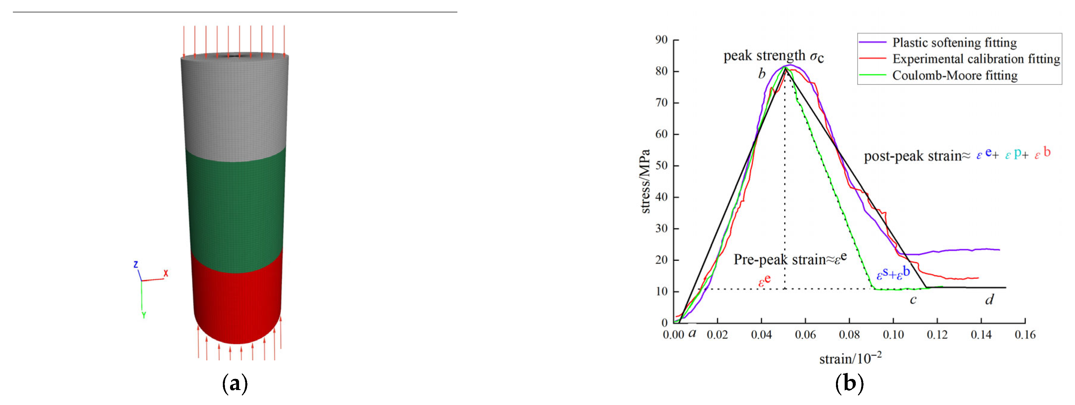
5.1. Selection of Constitutive Model and Parameter Calibration for Composite Roof

The numerical simulation analysis of mining-induced roadway composite roof strata is conducted using FLAC3D 6.0, a three-dimensional explicit finite difference software developed by Itasca Consulting Group, Inc., Minneapolis, MN, USA. Based on Lagrangian continuum theory, this software employs an explicit Lagrangian algorithm and a mixed-discretization zoning technique. By tracking particle trajectories, it accurately simulates the complete mechanical process of geomaterials—from elastic stages and plastic flow to ultimate failure—particularly excelling in modeling complex behaviors such as large deformations, material softening, and progressive failure.
In this study, a uniaxial compression test model for a composite of fine sandstone, medium sandstone, and sandy mudstone with a diameter of 50 mm was constructed using numerical simulation methods. The minimum grid size was established at 0.5 mm. The model featured a layered structure, comprising three distinct lithological units arranged axially with dimensions of 30 mm, 40 mm, and 30 mm, resulting in a total height of 100 mm, in accordance with international rock mechanics testing standards.
Full displacement constraints were applied to the bottom end face during the configuration of boundary conditions, while rigid pressure plates simulated the top loading face, effectively eliminating the influence of end friction on stress distribution.
To validate the accuracy of the established constitutive model in describing the mechanical response characteristics of the composite roof rock combination, a new uniaxial compression experiment was conducted on the rock combination sample. This involved a displacement control of 0.01 mm/s and a slow loading approach to avoid sudden changes in stiffness following the peak, which could arise from high load rates. As a result, comprehensive mechanical test results and dual calibration data from the simulations of the rock combination were successfully obtained (Figure 6, Figure 7, Figure 8, Figure 9, Figure 10, Figure 11 and Figure 12). The findings indicate that ABC-20 represents a rock mass combination characterized by a low proportion of soft rock, with the stress–strain relationship in the pre-peak phase of the three curves demonstrating linear growth. Notably, the elastic stage accounted for more than 80% of the total deformation, with pre-peak elastic deformation (εe) predominating the mechanical response of the rock mass combination. During this phase, the composite specimen formed a continuous load-bearing structure through the closed stress path of the stress shell, resulting in robust overall load-bearing performance for the surrounding rock composite.
When external loads exceeded the yield strength threshold of the sandy mudstone, the surrounding rock system exhibited distinct mechanical response characteristics across different zones. In such cases, low-strength surrounding rock units entered the strain softening stages of plastic slip (εp) and crack propagation (εb) first, while high-strength rock layers continued to sustain increasing bearing capacity through stress redistribution. Throughout the collaborative deformation process, rock layers with varying mechanical properties created stress gradients. Ultimately, supported by the high-strength rock layers, the entire system transitioned into a residual strength stage characterized by stable load-bearing capabilities.
Significant deviations were noted between the Mohr–Coulomb constitutive model and the experimental calibration results. The partitioned deformation during the post-peak stage of the composite roof necessitated the superposition of strains across the three stages—εe, εp and εb—to achieve a more precise characterization. A comparative analysis between the strain softening constitutive model results and the experimental calibration outcomes revealed that the relative error in the rate of post-peak stress decline was less than 5%. This model provides a more accurate representation of post-peak stress responses, uncovering the micro-mechanisms contributing to the residual bearing capacity of fractured surrounding rock in mining roadways. The application of the strain softening model effectively encapsulates the mechanical response characteristics throughout the entire process, from layered deterioration to overall instability of the composite roof in deep mining roadways.

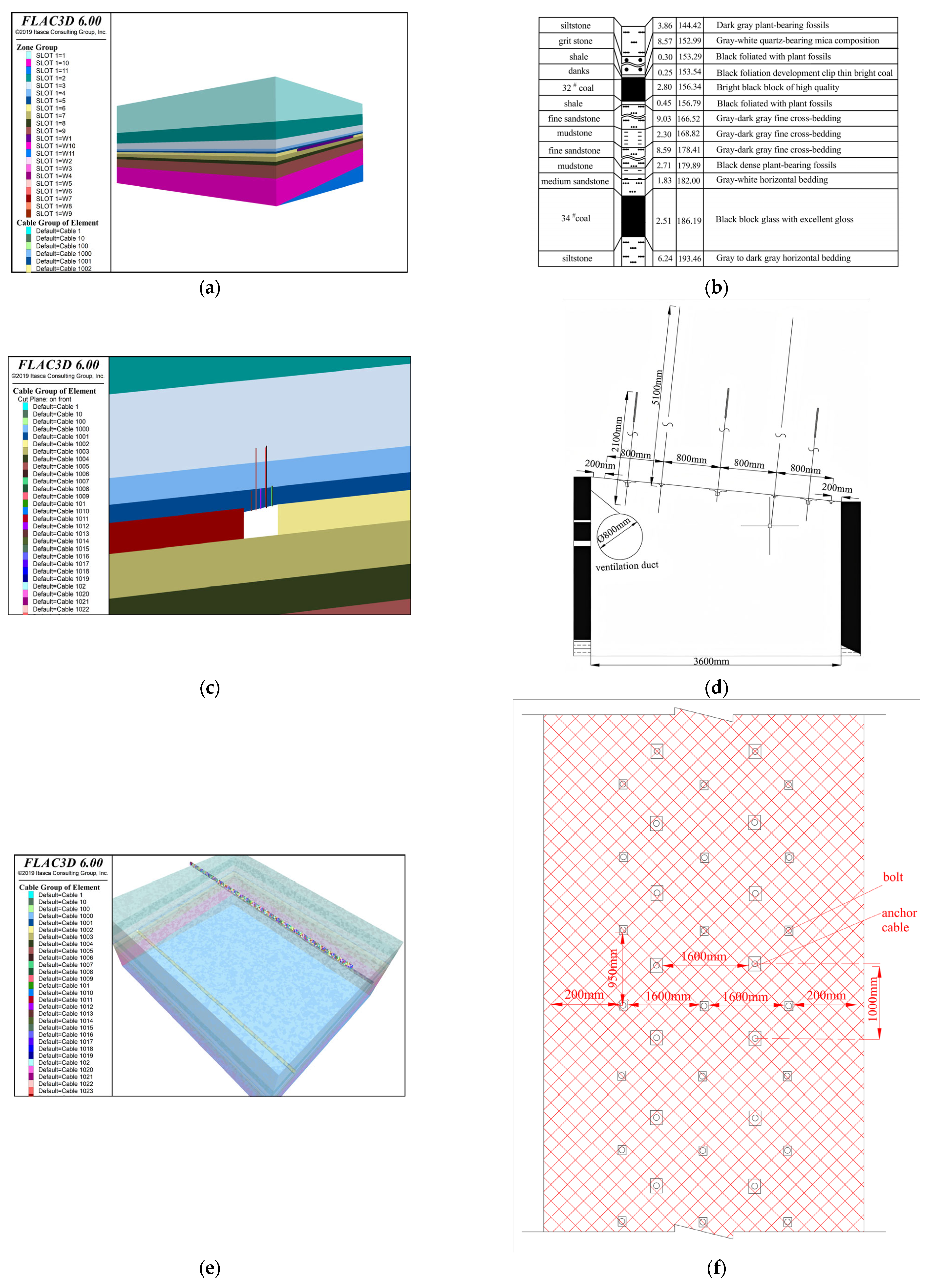
5.2. Model Establishment and Boundary Conditions

(1)
Numerical Model Setup
Based on the composite columnar diagram of the No. 34 coal seam in the Donghai Coal Mine (Figure 12b), a three-dimensional numerical model of the stope was established (Figure 12a). The model dimensions are 320 m (length) × 310 m (width) × 120 m (height). The equivalent self-weight stress at the top was calculated as 20 MPa, using an average overburden density of 25 kN/m3, applied perpendicular to the model’s upper surface. A lateral pressure coefficient of λ = 3 [28] was applied to simulate asymmetric stress concentration induced by intense mining activity. Horizontal displacement constraints were imposed on all side boundaries; the top boundary remained a free surface, and vertical displacement constraints were applied at the bottom. Physical and mechanical parameters were assigned as shown in Table 2.
(2)
Original Support Scheme Parameters
The left seventh roadway of the No. 34 coal seam primarily employs bolts and cable bolts for roof control. The scheme includes the following:
Bolts: Three φ20 mm threaded steel bolts, length L = 2100 mm, spaced at 1000 mm × 950 mm.
Cable bolts: Hook-connected cable bolts using φ21.8 mm steel strands, length L = 5100 mm, spaced at 1600 mm × 1000 mm.
A three-dimensional numerical model (Figure 12c,e) was constructed based on the field support layout (Figure 12d,f).
(3)
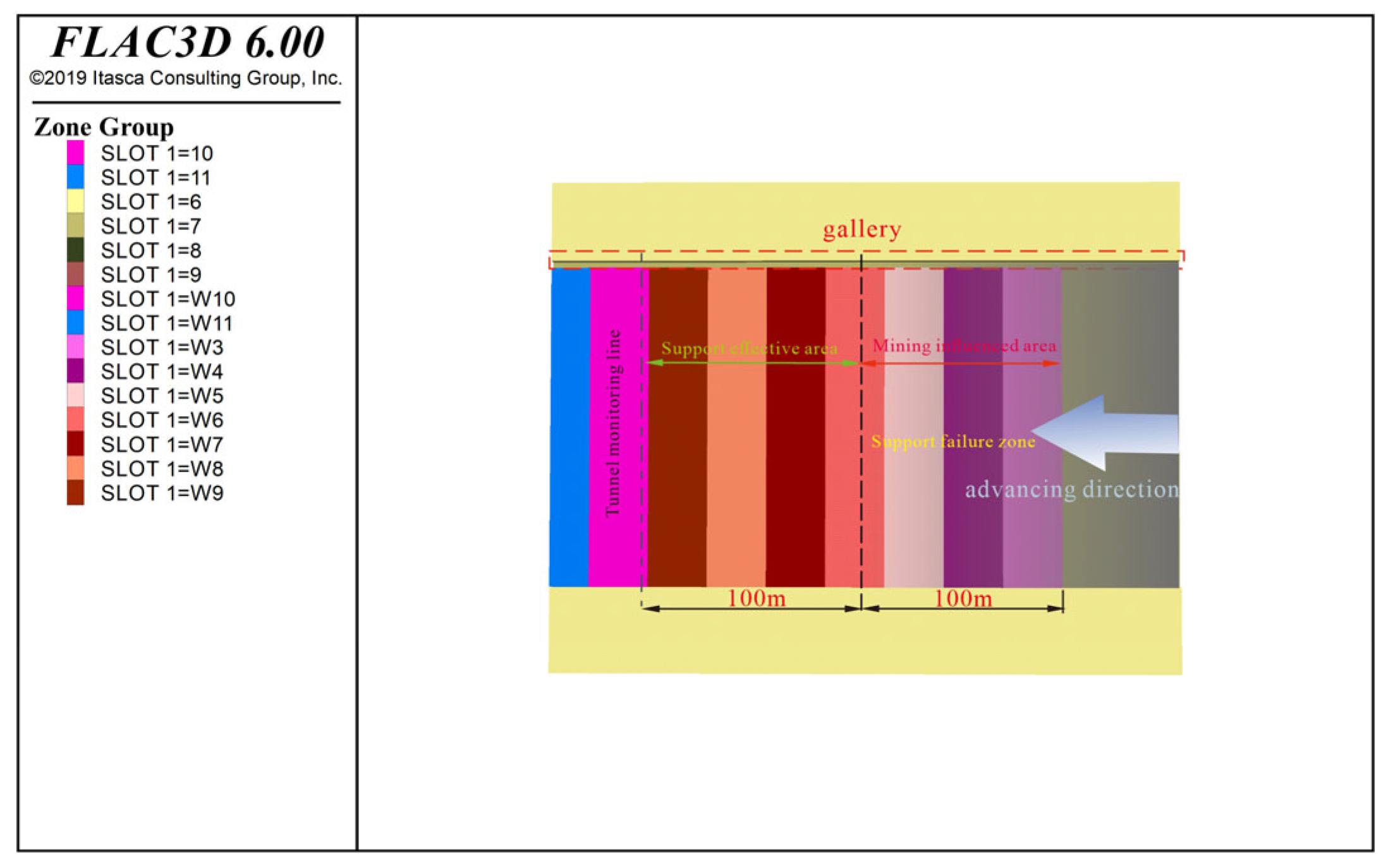
Advance and Monitoring
During the working face advance, stress distribution exhibited dynamic characteristics (Figure 13). The face advanced segmentally from the outer (right) to inner (left) direction, with each mining step spanning 30 m. Numerical simulations and field measurements demonstrate that the peak advanced abutment pressure within 100 m ahead of the face reached 79.2 MPa. This zone was defined as the primary mining influence area, with focused attention on stress concentration in the composite roof and plastic zone distribution of surrounding rock.
The distribution characteristics of principal stresses along the working face flank critically influence roadway stability. When principal stresses exceed the compressive strength of surrounding rock, failure occurs, exacerbating instability in composite roof strata. Thus, the effectiveness of the original support in the left seventh roadway of the No. 34 coal seam at the Donghai Coal Mine is validated through principal stress distribution analysis.
As the working face advances, stress redistribution occurs, whereby stresses around the working face gradually decrease and shift laterally. This results in distinct principal stress states along the flank. Figure 14a,b illustrate nephograms of maximum and minimum principal stress distributions. Within 30 m of the working face flank, a high-stress concentration zone (14 MPa–19.92 MPa) forms. The influence range of minimum principal stress spans 25 m, while elsewhere it remains relatively low (4 MPa–8 MPa).
Numerical monitoring results reveal significant spatial heterogeneity in principal stress distribution within the composite roof strata of the mining roadway under excavation influence. In the support-controlled zone 30 m ahead of the working face, intense stress concentration occurs in the roof strata. The peak maximum principal stress reaches 79.27 MPa—approximately 3.96 times the in situ stress 20 MPa—with a concentrated zone extending 7.9 m. This indicates severe mining-induced loading on the composite roof strata.
Principal stresses exhibit gradient attenuation with increasing distance from the working face:
At 30 m, stress reduces to 63 MPa. Between 30 and 50 m, it further declines to 56 MPa, reflecting dynamic adjustment of the stress field.
Within 50–80 m, the roadway remains within a strong mining disturbance zone. Stresses here, though lower than at the peak, still significantly exceed in situ levels. The original support fails to adapt to surrounding rock stresses, resulting in exponentially increasing roof-to-floor convergence as the face advances.
Beyond 80–100 m ahead of the working face, maximum principal stress stabilizes at 23 MPa, indicating exit from the significant mining influence zone.
Figure 14c illustrates that the maximum/minimum principal stress ratio (σ1/σ3) decays exponentially with increasing distance from the working face. Within 30 m of the working face, a high-stress differential zone forms with σ1/σ3 = 6–7. In the transition region of 30–80 m, the ratio decreases to 3–5, stabilizing at 1–3 beyond 80 m, indicating a recovery to the quasi-primary rock stress state. This stress evolution closely couples with the propagation pattern of plastic zones in the roof strata—when the principal stress direction forms a specific angle with structural planes, it readily induces the development of butterfly-shaped plastic zones, significantly increasing the risk of bed separation in compound roofs.
Within the high-stress differential zone, the interplay between elastic energy storage in fine-grained sandstone and plastic energy dissipation in sandy mudstone complicates energy release pathways. Fine-grained sandstone primarily stores elastic strain energy under high stress, particularly accumulating bending energy in stress deflection zones. As stored energy approaches peak strength limits, sudden energy release may occur, triggering roof fracture. Sandy mudstone undergoes plastic flow dominated by energy dissipation, while medium-grained sandstone—subjected to tensile-shear stresses and roadway surrounding rock loosening—forms the primary channel for energy release. Under unloading conditions, pervasive fractures develop internally, enabling rapid energy release along these fractures and inducing local roof falls or slip instability.

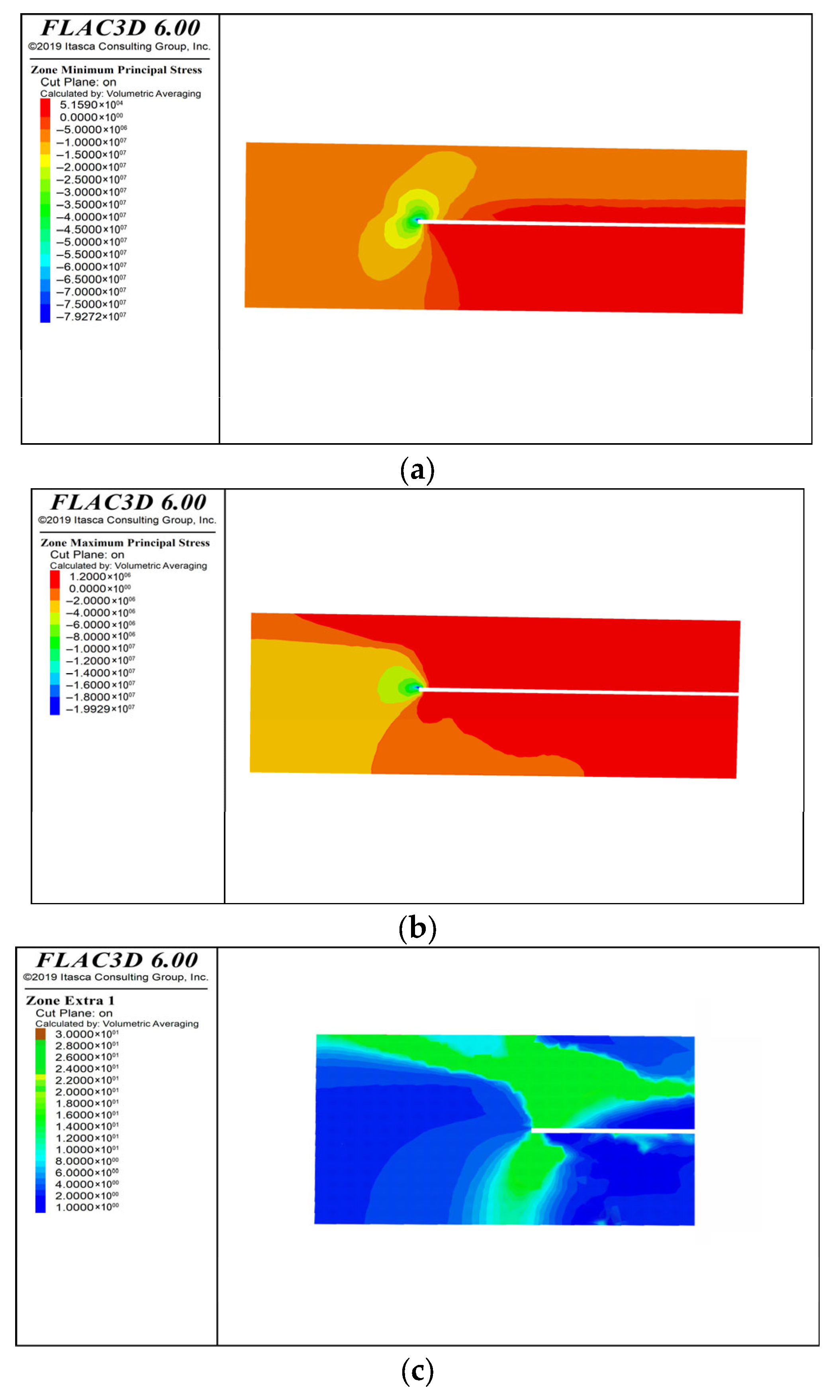
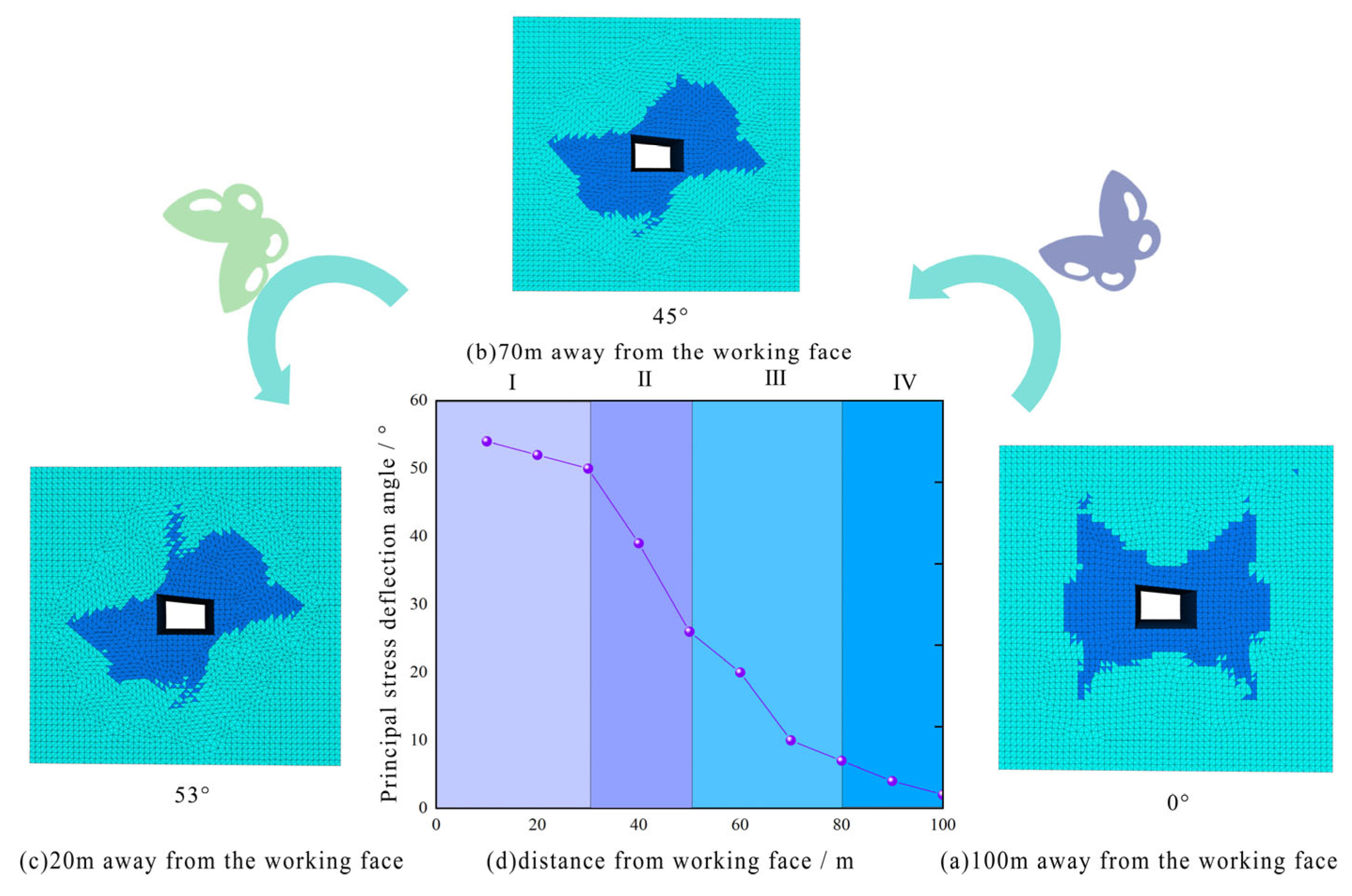
5.3. Deflection Calculation of Main Stress Field

The calculation of principal stress field deflection is based on classical mechanics methods for analyzing spatial oblique stresses. At any point in space, the three principal stresses Fx, Fy, and Fz can be determined through spatial coordinate transformation of six stress components (σx, σy, σz, τxy = τyx, τzx = τxz, τyz = τzy). The transformation procedure is detailed in Equations (12) to (16).
F x = l σ x + m τ y x + n τ z x F y = m σ y + n τ z y + l τ x y F z = n σ z + l τ x z + m τ y z
where l, m, and n are the direction cosines of the normal to the plane perpendicular to the loading direction, denoted as l = cos (N, x), m = cos (N, y), n = cos (N, z).
When the shear stress on an oblique plane at point F is zero, the normal stress on this plane is termed the principal stress at that point. This plane is defined as the principal stress plane, and its normal direction is the principal stress direction. For such a principal stress plane, since the shear stress vanishes, the total stress on the plane equals the normal stress (i.e., the principal stress σ). The components of the total stress along the coordinate axes can be expressed as follows:
F x = l σ x F y = m σ y F z = n σ z
Combine the above two equations:
( σ x σ ) l + τ y x m + τ z x n = 0 τ x y l + ( σ y σ ) m + τ z y n = 0 τ x z l + τ y z m + ( σ z σ ) n = 0
For three linear equations with direction cosines l, m, and n as variables, the principal stress directions at a point can be determined when the stress components and principal stresses at that point are known. The solution is given by the following equation. To determine the direction cosines l1, m1, and n1 corresponding to the principal stress σ1, any two equations from Equation (14) (e.g., the first and third equations) are solved simultaneously, yielding the following:
τ y x m 1 l 1 + τ z x n 1 l 1 + ( σ x σ 1 ) = 0 ( σ z σ 1 ) m 1 l 1 + τ x z n 1 l 1 + τ yz = 0
Further conversion yields the following:
l 1 = 1 1 + ( m 1 l 1 ) 2 + ( n 1 l 1 ) 2
By knowing the ratio m1/l1 and n1/l1, m1 and n1 can be solved. Similarly, using the same method, principal stresses in other directions can be solved separately. Based on the calculation results of the direction cosine, the specific direction of each principal stress at that point can be determined through trigonometric transformation.

5.4. Deterioration Response Characteristics of Composite Roof Under Mining Deflection Effect

As the working face advances continuously, the orientation of maximum principal stress in surrounding rock along the flank undergoes significant rotation, reaching a maximum deviation angle of 53 relative to the in situ stress direction. This stress vector rotation response primarily stems from altered stress paths induced by mining disturbance, which elevates vertical shear stress. Under compound roof conditions, the inherent soft-hard interbedded structure of rock strata, combined with increased vertical shear stress from mining, substantially reduces the shear strength of the roof structure, forming a characteristic butterfly-shaped deterioration pattern as shown in Figure 15.
Simultaneously, the following stress deflection evolution zones are identified:
Intense Rotation Zone (0–30 m from the working face): The principal stress ratio (σ1/σ3) continuously increases. The surrounding rock undergoes maximum deterioration. Rapid energy release drives the peak of the plastic zone upward to the direct roof apex. Rapid Attenuation Zone (30–50 m from the working face): The principal stress rotation angle decreases nonlinearly from 53° to 26°. The stress concentration coefficient drops from 1.6 to 0.8. This zone marks the transition from a plastic to an elastic state. Steady Recovery Zone (50–80 m from working face).
Maximum principal stress orientation approaches the original azimuth (deviation < 3°). Stress concentration coefficient stabilizes at 0.8–0.9. Mining influence progressively diminishes. Beyond 100 m ahead of the working face: The stress shell effect of the mining roadway becomes dominant. Rock mass essentially reverts to in situ stress state (rotation angle ≈ 0°). The surrounding rock resides in the ideal elastic zone. Original support satisfies control requirements in the steady recovery zone.
The core challenge in controlling the roof of the Zuoshang 7 return roadway in the No. 34 coal seam of the Donghai Coal Mine lies in the coupling effect between the dynamic evolution of the stress field induced by working face mining and the instability of the mechanical response of the compound roof. When the working face advances within 20 m of the roadway flank, the principal stress field in the surrounding rock undergoes significant directional adjustment, with the maximum principal stress rotating by 53 and the principal stress ratio reaching an asymmetric state of 1:7. This change causes simultaneous rotation and expansion of the butterfly-shaped plastic zone above the roof, forming a penetrative failure zone. At this stage, the depth of plastic deterioration reaches 7.5 m, exceeding the 5.1 m control range of the original cable bolts and highlighting the limitations of conventional cable bolts in controlling deep plastic zones.
The lithological differences in the compound roof (sandstone–sandy mudstone–medium sandstone) exacerbate the complexity of energy release pathways. Although the original symmetrical support system effectively suppresses shallow bed separation, it fails to adapt to the stress reorganization process triggered by severe rotation of the principal stress direction, causing the anchorage ends of cable bolts to detach from the elastic bearing zone. Mechanical disparities between compound rock layers further amplify control difficulties.
Therefore, roof control measures for the left 7 upper lane roadway should focus on restoring the load-bearing structure of the surrounding rock. By integrating the characteristics of the butterfly-shaped plastic zone and the rotation pattern of principal stress direction, differentiated synergistic support should be implemented.

6. Construction of Synergistic Control System for Composite Roof

Based on theoretical analysis and numerical simulation studies, a synergistic control technology system for the composite roof is established to address the engineering problem of instability caused by the original support’s inability to adapt to structural differences in the composite roof and mining-induced stress rotation. This system prioritizes fully mobilizing the self-bearing capacity of surrounding rock as its core principle. By constraining the development of non-coordinated deformation between composite roof layers and mitigating structural heterogeneity within layers through support measures, it actively regulates the dynamic balance between elastic strain energy and dissipated energy. This maintains the self-equilibrium stability of the surrounding rock system, guides microcrack development along predetermined paths, precisely controls crack propagation trajectories, and forms an ordered damage evolution mode from local to global scales. Consequently, it achieves synergistic control throughout the entire lifecycle of the composite roof—from stress redistribution optimization and progressive damage suppression to instability delay.

6.1. “Homogenization Constraint Energy Absorption” Multi-Level Bearing Synergistic Control Concept

(1)
Homogenization via Grouting Reinforcement
High-pressure permeation grouting is adopted to fill interlayer fractures and weak intercalations in the composite roof. This forms an integrated grout–vein network structure, inducing cementation and mechanical interlocking effects between lithologically distinct strata [29,30]. Thereby, stress transfer pathways are closed and reconstructed, achieving homogenization of the composite roof.
(2)
Rigid Constraint via Prestressed Cable Bolts
To address structural disparities-induced non-coordinated butterfly-shaped failure, high-strength prestressed cable bolt groups establish an active support system. This imposes spatial rigid constraints on surrounding rock deformation, transitioning the anchored zone into a triaxial stress state. It suppresses non-coordinated interlayer slippage and bed separation, particularly counteracting plastic zone rotation deterioration triggered by intense mining activity. Consequently, rigid constraints reinforce the load-bearing structure of the composite roof [31,32,33].
(3)
Energy Regulation via Energy-Absorbing Bolts
To address the disparities in energy absorption between soft and hard rock strata, energy-absorbing bolts are employed as an effective solution. While the bolt body is designed to endure tensile stress, its internal components dedicated to energy dissipation adeptly convert a portion of the elastic strain energy—generated by the deformation of rock—into alternative forms of energy for dissipation, thereby averting the risk of energy over-accumulation [34].
Constant-resistance energy-absorbing bolts leverage the frictional interactions between conical structures and sleeves to facilitate energy absorption. The energy that is released during this process is transformed into frictional energy within the support system, thereby enhancing the interfacial frictional resistance. This mechanism dynamically modulates the release of energy, ultimately culminating in the establishment of a self-stabilizing, energy-consolidated shell structure.

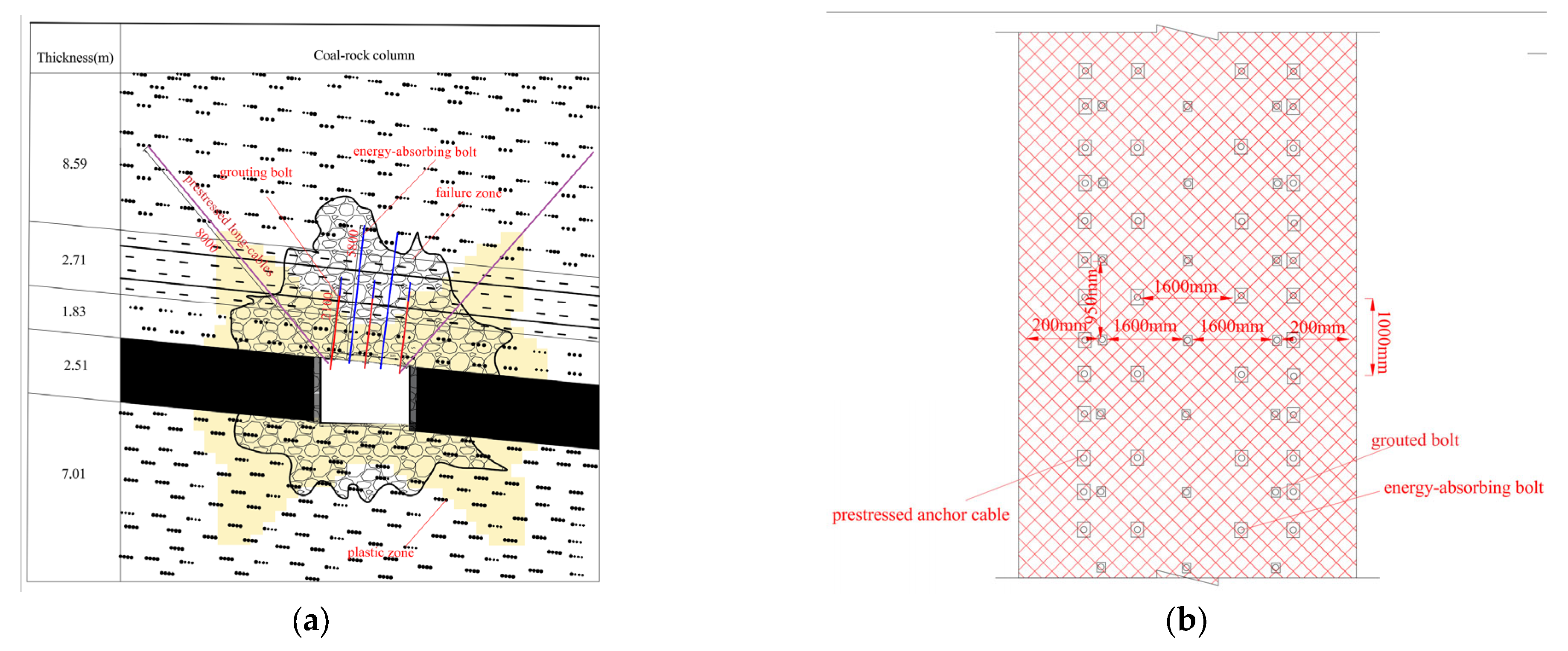
6.2. Design of Synergistic Control Scheme for Composite Roof in the Left 7 Upper Lane Return Roadway

(1)
Homogenization of Surrounding Rock
Experimental validation was undertaken utilizing Φ20 × 2100 mm grouting bolts and nano-silicate composite slurry under controlled parameters that included a diffusion radius of 5 m and grouting pressure maintained between 8 and 12 MPa. Post-grouting verification involved several key assessments:
(1) Confirming that the upper boundary of the grouted zone achieved the specified height of 1.83 m within the medium sandstone layer, in accordance with engineering standards. Verifying that the vein network fully enveloped the 2.71 m thick sandy mudstone layer. (2) Measuring a 20- to 25-fold expansion ratio upon contact with water, to validate the water–mudstone contact blocking effect. (3) Assessing a stable load-bearing structure of 3.8 m and a 65% improvement in stress transmission efficiency.
(2)
Rigid Constraint Reinforcement
Based on numerical modeling and similarity simulations, one primary instability factor in the left 7 upper lane working face is mining-induced stress triggering non-coordinated interlayer deformation. This causes a 53° directional rotation of the plastic zone, forming a butterfly-shaped expansion with a maximum deterioration radius of 7.93 m. To counteract this, two 8 m-long cable bolts are installed along the roof dip direction. A pretension force of 200 kN ensures anchorage ends penetrate sandy mudstone and embed 3.46 m into fine sandstone. The installation angle achieves mechanical orthogonality between the principal stress field and plastic zone expansion direction, aligning at 53°to the roadway section. Coupled with bottom metal mesh support, this approach effectively suppresses loosening of the surrounding rock. By regulating anchorage depth and pretension coupling, rigid constraints are established for the composite roof.
(3)
Coordinated Dynamic Energy Solidification
For energy accumulation and release path disparities in the composite roof, double rows of 5.8 m ultra-long constant-resistance energy-absorbing bolts are utilized. The conical friction mechanism enables “resistance-yield coordination.” Bolts penetrate three composite roof layers, traversing the neutral plane for full-length anchorage. The negative Poisson’s ratio effect enhances transverse confinement, maintaining support strength at 345 MPa constant resistance. Controlled slippage of 300–1000 mm within sleeves achieves graded energy dissipation and frictional reinforcement of the composite roof. The specific support design scheme is shown in Table 3, and the Synergistic support design diagram is shown in Figure 16.

7. Field Industrial Trial Evaluation

To validate the engineering applicability of the synergistic support system under complex geological conditions, the entrance of the No. 34 coal seam in the Donghai Coal Mine was selected for zonal industrial trials. Through dynamic monitoring of surrounding rock deformation and microseismic data indicators, the control efficacy of the synergistic support system on composite roof stability was systematically evaluated.

7.1. Monitoring Setup and Zoning

In the upper gateway area of the left 7 upper lane, a positioning matrix comprising 10 monitoring stations (S1–S10) was established. This matrix consisted of eight stations (S1–S8) positioned in the upper gateway and two stations (S9–S10) in the lower gateway, thereby forming a comprehensive three-dimensional monitoring network. The working face utilized a retreating longwall mining method, advancing from right to left along the seam strike. Based on the support conditions, the advance path was categorized into two observation zones relative to the working face:
Primary Zone: extending 0–100 m from the working face, this zone represents the original support area.
Synergistic Zone: spanning 100–200 m from the working face, this zone signifies the area optimized by the synergistic support system.

7.2. Deformation Control Effect of Synergistic Support

Following the implementation of synergistic control support (Figure 17a), a cross-grid method was employed for continuous monitoring over a duration of 90 days. Post-optimization, the stabilized deformation stage advanced from day 45 to day 40. The previously irregular large-deformation section transitioned into a minor-deformation planar section (Figure 17c). Notably, the maximum roof-to-floor convergence decreased from 955 mm to 493 mm, and the rib-to-rib convergence reduced from 516 mm to 313 mm. These results confirm that the optimized support effectively activates the load-bearing capacity of the surrounding rock, thereby shortening the self-stabilization period by approximately 11% (Figure 17b).

7.3. Microseismic Data Analysis with Statistical Summarization

Mining activities disrupted the original stress state of the surrounding rock, altering its bearing structure and triggering synchronous microseismic responses within the composite roof region. Microseismic events were predominantly concentrated during mining operations, with all 10 stations successfully detecting signals. Here, we present a statistical summarization of the characteristics of microseismic events, utilizing mean, standard deviation, and maximum values—metrics crucial for understanding energy distribution patterns:
a.
Average Energy
In the Primary (original support) zone, the average energy of microseismic events was measured at 2.8 × 10³ J (Table 4). In stark contrast, the Synergistic (optimized support) zone exhibited a substantially reduced average energy of 1.0 × 101 J, reflecting an extraordinary decline rate of 99.6%. This significant reduction indicates that the synergistic support system effectively mitigates the average energy release in the surrounding rock.
b.
Maximum Energy
The maximum energy of microseismic events in the Primary zone reached 9.2 × 10⁴ J, indicative of intense energy release potential. Conversely, in the Synergistic zone, the maximum energy was suppressed to 3.5 × 10² J, also demonstrating a 99.6% decline rate (Table 4). This suppression of extreme energy-releasing events enhances roof stability.
c.
Energy Standard Deviation
The energy standard deviation in the Primary zone was ±4.1 × 10³, signifying highly variable energy release patterns (Table 4). In the Synergistic zone, the standard deviation decreased to ±8.7 × 101, representing a 97.9% decline. A lower standard deviation suggests more uniform and predictable microseismic behavior, indicating improvements in surrounding rock stability under synergistic support.
d.
Proportion of High-Energy Events
High-energy events (defined as >103 J in the Primary zone and >102 J in the Synergistic zone for comparative analysis) accounted for 68% of total events in the Primary zone. In the Synergistic zone, this proportion plummeted to 12%, reflecting an 82.4% decline rate (Table 4). The optimized support effectively suppresses the frequency of high-energy events, further validating its role in maintaining composite roof stability.
The synergistic support system exhibits remarkable efficacy in both deformation control and microseismic energy management. It not only advances the stabilized deformation stage, reduces convergence values, and shortens the self-stabilization period in terms of deformation, but it also demonstrates significant improvements from the microseismic perspective. Through comprehensive statistical metrics—namely the mean, standard deviation, and maximum values—the system effectively reduces both average and extreme energy releases, stabilizes energy release patterns, and suppresses the proportion of high-energy events. These outcomes collectively provide compelling evidence of the system’s capability to maintain composite roof stability under complex geological conditions, effectively activating the load-bearing capacity of surrounding rock and mitigating the impacts induced by mining activities.

7.4. Economic Benefit Analysis

As described in Table 5, the optimized support system provides significant economic benefits through various channels. It enhances layout efficiency and activates the surrounding rock’s self-bearing capacity, leading to a 48.4% reduction in roof-to-floor convergence and a 39.3% decrease in rib-to-rib convergence. This improvement lowers repair frequency from three to one annually, resulting in savings of CNY 240,000–360,000 per 100 m. Additionally, using high-strength lightweight materials cuts steel consumption by 15–20%, saving an extra CNY 80,000–120,000 in material costs.
The system also compresses the construction period by reducing the self-stabilization time from 45 to 40 days, which yields significant savings in equipment and labor costs. The risk of roof collapse decreases, with probabilities falling from 8% to below 2%, effectively avoiding annual losses of CNY 120,000 to 180,000. Overall, the annualized net benefit of the optimized support system ranges from CNY 1.44 to 1.66 million per 100 m, underscoring its economic efficiency and operational effectiveness.

8. Discussion

This study systematically investigates the mechanisms underlying the instability of composite roof surrounding rock in mining-induced roadways and proposes a synergistic control system. The findings represent significant advancements in both theoretical analysis and practical applications. However, as with any scholarly endeavor, limitations exist that warrant further examination, alongside prospects for future investigations.

8.1. Theoretical and Practical Significance

The establishment of mechanical equilibrium equations for the elastic, plastic, and fracture zones elucidates the critical roles that rigid cohesion and softening cohesion play in defining the bearing capacity of the composite roof. This formulation provides a robust theoretical framework for quantifying roof stability. The FLAC3D simulations, employing a strain softening model with a post-peak stress drop error of less than 5%, effectively illustrate the evolution of the roof’s elastic, plastic, and rupture phases. Notably, these simulations underscore the influence of high-stress difference zones, characterized by a maximum-to-minimum principal stress ratio ranging from 6 to 7, and stress deflection angles of 53 degrees within 20 m of the working face, offering pivotal insights into the factors contributing to mining-induced instability.
Field tests validate the efficacy of the synergistic control system, demonstrating significant reductions in roof-to-floor convergence by 48.4%, two-side convergence by 39.3%, microseismic events by 61%, and energy release by 82%. Furthermore, the self-stabilization period is shortened by 11%, underscoring the system’s technical and economic viability. These results confirm that structural homogenization, reinforcement through rigid constraints, and the solidification of energy regulation can work in concert to enhance the bearing capacity of composite roofs, thereby providing a practical solution for deep mining roadways.

8.2. Limitations and Future Work

A notable limitation of this study is the lack of a comprehensive evaluation regarding the long-term durability of grouting materials under sustained mining pressures. While the synergistic control system exhibits commendable short-term performance, the potential attenuation of the mechanical properties of grouting bodies over time—due to factors such as water erosion, cyclic stress, or material aging—remains inadequately understood. This uncertainty may pose risks to the long-term stability of the composite roof.
To address these concerns, future research will prioritize the following avenues:
(1) Long-term In Situ Monitoring: Extensive monitoring of grouting body performance over a period of 3 to 5 years, focusing on critical parameters including uniaxial compressive strength, cohesion, and permeability. (2) Indoor Accelerated Aging Tests: Implementing accelerated aging experiments that replicate mine environmental conditions characterized by high stress, humidity, and chemical corrosion to develop attenuation models for the properties of grouting materials. (3) Optimization of Grouting Materials: Investigating the formulation of grouting materials by incorporating nano-reinforcements or anti-aging agents to enhance long-term durability, thereby improving the sustained effectiveness of the control system.
By pursuing these research directions, the goal is to fortify understanding and application of composite roof stabilization strategies in the context of deep mining operations.

9. Conclusions

This study investigates the stability control of the composite roof surrounding rock in mining-induced roadways, elucidating the comprehensive evolution mechanism of roof instability due to mining disturbances. A synergistic control technology system has been established, comprising structural homogenization of the surrounding rock, rigid constraint reinforcement, and energy regulation solidification, all validated through extensive field trials. Significant findings include the following:
The mechanical equilibrium equations for the elastic, plastic, and fracture zones were developed, revealing that both rigid cohesion parameters and softening cohesion play crucial roles in determining the bearing capacity of the composite roof. The initial in situ stress conditions in the Donghai Coal Mine, characterized by a stress level of 20 MPa, demonstrate that support resistance significantly influences the deterioration radii of the plastic zone, measured at 4.44 m, and the failure zone, identified at 3.86 m.
By employing the strain softening model within FLAC3D, the study achieved a simulation error of less than 5% concerning post-peak stress drop, effectively capturing the elastic–plastic–rupture stages of the composite roof. A pronounced high stress difference zone, with a ratio of maximum-to-minimum principal stress between 6 and 7, was observed within 20 m of the working face. This condition led to a maximum principal stress deflection angle of 53 degrees, contributing to the instability of the mining roadway’s composite roof.
A synergistic control system was proposed to enhance the bearing structure of the composite roof through various reinforcement techniques, including high-pressure grouting and prestressed anchor cables. Field tests revealed significant reductions in roof-to-floor convergence by 48.4%, two-side convergence by 39.3%, microseismic events by 61%, and energy release by 82%. Furthermore, the system shortened the self-stabilization period by 11%, resulting in substantial economic benefits. This comprehensive approach provides an effective and economically viable solution for managing the composite roof in deep mining roadways.

Author Contributions

Conceptualization, L.W.; methodology, L.W.; software, Y.S.; validation, L.W.; formal analysis, Y.S.; investigation, Y.Z. and D.L.; resources, G.L. and D.L.; data curation, L.W.; writing the original draft, L.W. and Y. S; writing, review and editing, L.W. and Y.S.; visualization, L.W. and G.L.; supervision, L.W.; project administration, G.L. and Y.Z.; funding acquisition, G.L. and Y.Z. All authors have read and agreed to the published version of the manuscript.

Funding

This work was supported by the Scientific and Technological Key Project of “Revealing the List and Taking Command” in Heilongjiang Province (2021ZXJ02A03, 2021ZXJ02A04).

Data Availability Statement

The original contributions presented in this study are included in the article. Further inquiries can be directed to the corresponding author.

Conflicts of Interest

Dali Lin was employed by the Heilongjiang Longmei Jixi Mining Co., Ltd., and Yongtao Zhu was employed by the Heilongjiang Longmei Shuangyashan Mining Co., Ltd. The remaining authors declare that the research was conducted in the absence of any commercial or financial relationships that could be construed as a potential conflict of interest.

References

  1. Raza, M.A.; Karim, A.; Aman, M.M.; Al-khasawneh, M.A.; Faheem, M. Global progress towards the Coal: Tracking coal reserves, coal prices, electricity from coal, carbon emissions and coal phase-out. Gondwana Res. 2025, 139, 43–72. [Google Scholar] [CrossRef]
  2. Xiong, X.; Ouyang, Y.; Dai, J.; Ling, Z. Analysis and control of self stable balance circle of surrounding rock of roadway in inclined coal seam. Appl. Math. Model. 2023, 124, 749–767. [Google Scholar] [CrossRef]
  3. Wu, X.; Wang, S.; Gao, E.; Chang, L.; Ji, C.; Ma, S.; Li, T. Failure mechanism and stability control of surrounding rock in mining roadway with gentle slope and close distance. Eng. Fail. Anal. 2023, 152, 107489. [Google Scholar] [CrossRef]
  4. Zhao, Y.X.; Zhou, J.L.; Zhang, C.; Liu, B.; Ling, C.-W.; Liu, W.-C.; Han, C.-J. Failure mechanism of gob-side roadway in deep coal mining in the Xinjie mining area: Theoretical analysis and numerical simulation. J. Cent. South Univ. 2023, 30, 1631–1648. [Google Scholar] [CrossRef]
  5. Li, Z.; Zhou, Y.; Xu, X.; Xiao, Y.; Xu, Y. The mechanistical principles and engineering application of roof-cutting for roadway protection in advance of the working face. Sci. Rep. 2025, 15, 1660. [Google Scholar] [CrossRef]
  6. Zhang, P.F.; Gu, X.B.; Guo, W.Y.; Zhao, T.-B.; Gong, X.-F.; Zhu, Z.-Q.; Guo, L. Bending energy storage mechanical model of layered composite roof structure in coal mining. Sci. Rep. 2024, 14, 30976. [Google Scholar] [CrossRef]
  7. Chai, Y.; Dou, L.; Cai, W.; Małkowski, P.; Li, X.; Gong, S.; Bai, J.; Cao, J. Experimental investigation into damage and failure process of coal-rock composite structures with different roof lithologies under mining-induced stress loading. Int. J. Rock Tech. Min. Sci. 2023, 170, 105479. [Google Scholar] [CrossRef]
  8. Wang, J.; Zhang, Q.; Zhang, J.; Liu, H.; Zhu, G.; Wang, Y. Study on the controller factors associated with roof falling and ribs spalling in deep mine with great mining height and compound roof. Eng. Fail. Anal. 2021, 129, 105723. [Google Scholar] [CrossRef]
  9. Qiu, L.; Dang, J.; Zhang, J.; Zhang, J.; Wang, M.; Liu, Q.; Si, L.; Jiang, Z.; Khan, M. Investigating nonlinear resistivity characteristics and mechanisms of coal during various loading stages. J. Appl. Geophys. 2025, 238, 105705. [Google Scholar] [CrossRef]
  10. Zhou, H.; Song, M.; Zhang, C.Q.; Lu, J.J.; Liu, Z.J.; Shi, L.K. Study on the confining pressure effect on deformation and failure characteristics of horizontal layered composite rock mass. Rock Soil Mech. 2019, 40, 465–473. [Google Scholar] [CrossRef]
  11. Zhang, W.D.; Tao, H.F.; Yang, J.; Wang, Y.; Chang, Z.G. Technology of narrow coal pillar width and surrounding rock control for gob-side entry driving in soft and broken composite roof. Saf. Coal Mines 2023, 54, 132–139. [Google Scholar] [CrossRef]
  12. Song, D.; Liu, Q.; Qiu, L.; Zhang, J.; Khan, M.; Peng, Y.; Zhao, Y.; Wang, M.; Guo, M.; Hong, T. Experimental study on resistivity evolution law and precursory signals in the damage process of gas-bearing coal. Fuel 2024, 362, 130798. [Google Scholar] [CrossRef]
  13. Zuo, J.P.; Yu, M.l.; Sun, Y.J.; Wu, G.S. Mechanism and mechanical model analysis of fracture mode transition of rock layers with different thicknesses. J. China Coal Soc. 2023, 48, 1449–1463. [Google Scholar] [CrossRef]
  14. Jia, H.S.; Pan, K.; Liu, S.W.; Zhang, L.; Fan, K.; Niu, Z.; Zhuo, J.; Wang, Q. Delamination failure mechanism and prediction method of composite roof in mining roadway. J. Min. Saf. Eng. 2021, 38, 518–527. [Google Scholar] [CrossRef]
  15. Jiang, L.S.; Ma, N.J.; Bai, L.; Li, Y.j.; Zhang, L. Deformation and failure characteristics of roadway composite roof and classification of roof-fall hazard. J. China Coal Soc. 2014, 39, 1205–1211. [Google Scholar] [CrossRef]
  16. Kang, H.P.; Gao, F.Q. Evolution of mining-induced stress and surrounding rock control in coal mines. Chin. J. Rock Tech. Eng. 2024, 43, 1–40. [Google Scholar] [CrossRef]
  17. Kang, H.P. Analysis of types and interactions of in-situ stress fields in coal mines. J. China Coal Soc. 2008, 33, 1329–1335. [Google Scholar]
  18. Kang, H.P.; Wang, G.F.; Jiang, P.F.; Wang, J.; Zhang, N.; Jing, H.; Huang, B.; Yang, B.; Guan, X.; Wang, Z. Conception for strata control and intelligent mining technology in deep coal mines with depth over 1000 m. J. China Coal Soc. 2018, 43, 1789–1800. [Google Scholar] [CrossRef]
  19. Kang, H.P.; Lin, J.; Yan, L.X.; Zhang, X.; WU, Y.Z.; SI, L.P. Study on characteristics of in-situ stress field distribution in underground coal mines in Shanxi mining area. Chin. J. Geophys. 2009, 52, 1782–1792. [Google Scholar]
  20. Kang, H.P. Sixty years development and prospects of rock bolting technology for coal mine roadways in China. J. China Univ. Min. Technol. 2016, 45, 1071–1081. [Google Scholar] [CrossRef]
  21. Zhang, L.X.; Wei, X.J.; Liu, G.C. Application research on grouting reinforcement technology for broken surrounding rock in 1366 mining roadway. J. Min. Sci. Technol. 2023, 8, 583–592. [Google Scholar] [CrossRef]
  22. Li, G.C.; Hao, H.R.; Sun, Y.T.; Sun, Y.; Li, J.; Yang, S.; Shao, Z.; Wo, X. Principle and technology of stepwise reinforcement control for soft rock argillized roadway in coal mine. J. China Coal Soc. 2025, 50, 810–823. [Google Scholar] [CrossRef]
  23. Li, G.C.; Yang, S.; Sun, Y.T.; Xu, J.H.; Li, J.H. Research progress on surrounding rock control technology of roadways under complex conditions. Coal Sci. Technol. 2022, 50, 29–45. [Google Scholar] [CrossRef]
  24. Zhang, Z.Q. Spatiotemporal Evolution Characteristics of Surrounding Rock Stress Shells and Support Mechanisms in Deep Roadways. Ph.D. Dissertation, China University of Mining and Technology, Beijing, China, 2019. [Google Scholar]
  25. Li, Y.; Zhai, C.; Ding, X. Study on the influence of deep horizontal principal stress direction on the stability of surrounding rock in coal roadway. Coal Eng. 2023, 55, 86–92. [Google Scholar]
  26. Li, J.; Ren, J.; Li, C.; Zhang, W.; Tong, F. Failure Mechanism and Stability Control of Soft Roof in Advance Support Section of Mining Face. Minerals 2023, 13, 178. [Google Scholar] [CrossRef]
  27. Ma, N.; Zhao, X.; Zhao, Z.; Li, J.; Guo, X. Stability analysis and control of surrounding rock in deep mining roadway. J. China Coal Soc. 2015, 40, 2287–2295. [Google Scholar] [CrossRef]
  28. Liu, H.T.; Han, Z.J.; Han, Z.; Huo, T.H.; Luo, M.; Luo, Z.L.; Peng, J.C.; Zhang, H.K. Mechanism of non-uniform expansion and stability control in surrounding rock failure zone due to superimposed mining. J. Min. Saf. Eng. 2024, 41, 522–532. [Google Scholar] [CrossRef]
  29. Li, Q.L.; Zhao, G.M.; Wang, Y.F.; Zeng, X.; Cheng, X.; Li, Y.; Meng, X. Performance and Microstructure Characteristics of Cement-Sodium Silicate Double-Liquid Grouting Material. Coal Mine Saf. 2025, 56, 136–145. [Google Scholar] [CrossRef]
  30. Kang, H.P.; Yi, K. Simulation study and application of dilatancy and rheological characteristics of surrounding rock in deep soft rock roadways. J. China Coal Soc. 2023, 48, 15–33. [Google Scholar] [CrossRef]
  31. Han, C.; Yuan, Y.; Ding, G.; Li, W.; Yang, H.; Han, G. The Active Roof Supporting Technique of a Double-Layer Flexible and Thick Anchorage for Deep Withdrawal Roadway under Strong Mining Disturbance. Appl. Sci. 2023, 13, 12656. [Google Scholar] [CrossRef]
  32. Qian, D.; Jiao, H.; Deng, J.; Yang, J.; Jiao, M.; Xian, G.; Li, B. Instability Mechanism, Pressure Relief, and Long Anchorage Control Countermeasures for Surrounding Rock of Strong Mining Roadway at Large Mining Height Working Face. Minerals 2023, 13, 391. [Google Scholar] [CrossRef]
  33. Song, Z.P.; Xu, X.J.; Liu, W.; Li, J. Research review on energy-absorbing bolts and their static and dynamic testing methods. Mod. Tunn. Technol. 2023, 60, 1–13. [Google Scholar] [CrossRef]
  34. Xiao, X.; Xu, Z.; Fan, Y. Research status and prospects of energy-absorbing anchor support equipment. Coal Sci. Technol. 2025, 53, 54–64. [Google Scholar] [CrossRef]
Figure 1. Current state of surrounding rock control in the left seventh roadway of the No. 34 coal seam in the Donghai Coal Mine: (a) Comprehensive bar chart; (b) Roadway deformation photos; (c) Deformation monitoring data.
Processes 13 02342 g001
Figure 2. Overview of on-site engineering: (a) Mining engineering plan; (b) Roadway support section diagram.
Processes 13 02342 g002
Figure 3. Pre-processing of surrounding rock combination.
Processes 13 02342 g003
Figure 4. Wave velocity test of surrounding rock combination: (a) Longitudinal wave velocity; (b) Shear wave speed.
Processes 13 02342 g004
Figure 5. Stress–strain curves: (a) Stress-strain curves of monolithic rock specimens; (b) Stress–strain curve of the composite rock specimen.
Processes 13 02342 g005
Figure 6. Theoretical model of deterioration of surrounding rock across structural zones: (a) Stress-strain curve of surrounding rock monomer; (b) Stress–strain curve of the surrounding rock combination body.
Processes 13 02342 g006
Figure 7. Evolution of surrounding rock zoning in the No. 34 coal seam of the Donghai Coal Mine.
Processes 13 02342 g007
Figure 8. Influence cohesion on the partition radius of roadway surrounding rock: (a,b) Cohesive force of hard rock.
Processes 13 02342 g008
Figure 9. Influence of in situ stress on deterioration radii: (a) Radii variation; (b) Partition criterion.
Processes 13 02342 g009
Figure 10. Influence of support resistance factors on the evolution characteristics of the deterioration radius of roadway surrounding rock.
Processes 13 02342 g010
Figure 11. Calibration curve for numerical analysis and mechanical testing: (a) Calibration curve of numerical model; (b) Calibration curve.
Processes 13 02342 g011
Figure 12. Comparison between the numerical model and the prototype: (a) Three-dimensional numerical model (solid); (b) Comprehensive columnar formation; (c) Three-dimensional numerical model (support spacing); (d) Support section; (e) Three-dimensional numerical model (support spacing); (f) Support spacing.
Processes 13 02342 g012
Figure 13. Working face advancement and excavation.
Processes 13 02342 g013
Figure 14. Mining roadway composite roof stress characteristics: (a) Maximum principal stress; (b) Minimum principal stress; (c) Distribution of principal stress ratio.
Processes 13 02342 g014
Figure 15. Deflection shape of the plastic zone of the surrounding rock.
Processes 13 02342 g015
Figure 16. Synergistic support design diagram: (a) Supporting section diagram; (b) Top view of support.
Processes 13 02342 g016
Figure 17. Field industrial test monitoring: (a) On site construction scene; (b) Displacement of surrounding rock after synergistic support; (c) The situation of the roadway after synergistic support; (d) Microseismic acquisition event.
Processes 13 02342 g017
Table 1. Physical and mechanical parameters of composite roof strata.
Rock Typeσc (MPa)σt (MPa)E (GPa)μ
(Dimensionless Quantity)
C (MPa)φ/(°)v/(m/s)
fine sandstone120.195.3112.460.188.1136.402700
Medium
sandstone
97.602.8110.970.155.3732.102310
sandy mudstone35.141.052.800.282.4525.132080
Table 2. Calculated deterioration radii of surrounding rock zones without support.
Scope of Influence
RoadwayFracture ZonePlastic ZoneElastic Zone
Range/m 0~22~7.137.13~7.937.93~∞
Influence area/m 05.130.87.93~∞
Radiation radius/m27.137.93
Table 3. Synergistic control support design scheme.
Control LevelTechnical ParametersPrimary Action ZoneMechanism of
Action
Engineering Standards
Structural HomogenizationGrouting bolts: Φ 20 × 2100 mm
Diffusion radius: 5 m
Grouting pressure: 8–12 MPa
Grout type: Nano-silicate composite slurry
(After encountering water, the expansion ratio reaches 20–25 times, blocking the contact between water and mudstone)
Sandy mudstoneFracture filling + interfacial bonding
Forms composite Stable load-bearing structure (thickness: 3.8 m)
Stress transmission efficiency increased by 65%
Grouting zone upper boundary: 1.83 m height (medium sandstone)
Grout vein network covers entire sandy mudstone layer (2.71 m)
Rigid Constraint Reinforcement Prestressed cable bolts:
Φ 21.8 × 8000 mm
Pretension force: 200 kN
Installation angle: 53°
Anchorage depth: 3.46 m (into fine sandstone)
Fine sandstoneForms butterfly-shaped rigid constraint
Enhancement of interlayer shear stiffness
Suppresses loosening circle expansion
Cable bolt group penetrates butterfly zone
Forms 53° spatial angle with metal mesh plane
Coordinated Energy SolidificationAnchor bolt parameters: Φ 32 × 5800 mm (Three segment splicing)
Constant resistance value: 345 MPa
Slip amount: 300–1000 mm
Energy absorption: 4.23 times that of conventional anchor rods
Fine sandstone,
Medium sandstone,
Sandy mudstone
Graded energy dissipation: Elastic phase: 0–300 mm
Plastic phase: 300–1000 mm
Double-row layout
Penetrates composite roof strata
Table 4. Energy distribution statistics.
ParameterOriginal Support AreaSynergistic Support AreaDecline Rate
Average Energy (J)2.8 × 1031.0 × 10199.6%
Maximum Energy (J)9.2 × 1043.5 × 10299.6%
Energy Standard Deviation (J)±4.1 × 10³±8.7 × 10197.9%
Proportion of High-Energy Events (%)68% (>103 J)12% (>102 J)82.4%
Table 5. Economic Benefit Analysis.
IndicatorTraditional Support Scheme (CNY)Synergistic Support Scheme (CNY)Unit Savings/Gain (CNY)
Annual Repair Cost (100 m)360,000–540,000120,000–180,000240,000–360,000
Support Material Cost (100 m)500,000–600,000420,000–480,00080,000–120,000
Annual Accident Risk Loss160,000–240,00040,000–60,000120,000–180,000
Production Increase Benefit (Working Face/Year)01,000,0001,000,000
Comprehensive Annualized Net Benefit1,440,000–1,660,000 per 100 m
Disclaimer/Publisher’s Note: The statements, opinions and data contained in all publications are solely those of the individual author(s) and contributor(s) and not of MDPI and/or the editor(s). MDPI and/or the editor(s) disclaim responsibility for any injury to people or property resulting from any ideas, methods, instructions or products referred to in the content.

