Article

Effect Mechanism of Phosphorus-Containing Flame Retardants with Different Phosphorus Valence States on the Safety and Electrochemical Performance of Lithium-Ion Batteries

1
School of Chemical Safety, North China Institute of Science and Technology, Beijing 101601, China
2
College of Safety Science and Engineering, Nanjing TBCH University, Nanjing 210009, China
3
School of Chemical and Environmental engineering, China University of Mining and Technology (Beijing), Beijing 10083, China
*
Authors to whom correspondence should be addressed.
Processes 2025, 13(7), 2248; https://doi.org/10.3390/pr13072248
Submission received: 16 May 2025 / Revised: 5 July 2025 / Accepted: 9 July 2025 / Published: 14 July 2025
(This article belongs to the Section Chemical Processes and Systems)

Abstract

With the widespread application of lithium-ion batteries (LIBs), safety performance has become a critical factor limiting the commercialization of large-scale, high-capacity LIBs. The main reason for the safety problem is that the electrolytes of LIBs are extremely flammable. Adding flame retardants to conventional electrolytes is an effective method to improve battery safety. In this paper, trimethyl phosphate (TMP) and trimethyl phosphite (TMPi) were used as research objects, and the flame-retardant test and differential scanning calorimetry (DSC) of the electrolytes configured by them were first carried out. The self-extinguishing time of the electrolyte with 5% TMP and TMPi is significantly reduced, achieving a flame-retardant effect. Secondly, the electrochemical performance of LiFePO4|Li half-cells after adding different volume ratios of TMP and TMPi was studied. Compared with TMPi5, the peak potential difference between the oxidation peak and the reduction peak of the LiFePO4|Li half-cell with TMP5 added is reduced, the battery polarization is reduced, the discharge specific capacity after 300 cycles is large, the capacity retention rate is as high as 99.6%, the discharge specific capacity is larger at different current rates, and the electrode resistance is smaller. TMPi5 causes the discharge-specific capacity to attenuate, which is more obvious at high current rates. LiFePO4|Li half-cells with 5% volume ratio of flame retardant have the best electrochemical performance. Finally, the influence mechanism of the phosphorus valence state on battery safety and electrochemical performance was compared and studied. After 300 cycles, the surface of the LiFePO4 electrode with 5% TMP added had a smoother and more uniform CEI film and higher phosphorus (P) and fluorine (F) content, which was beneficial to the improvement of electrochemical performance. The cross-section of the LiFePO4 electrode showed slight collapse and cracks, which slowed down the attenuation of battery capacity.

1. Introduction

Lithium-ion batteries, with their high energy density and high voltage, have become a research hotspot for energy storage devices and have been widely used in small portable devices and energy storage power stations [1]. At present, most lithium-ion batteries use highly flammable organic carbonate solvents as the main component of the electrolyte. These electrolytes have a low flash point and pose a great safety hazard. Due to the high energy density of lithium-ion batteries, overcharging or short-circuiting can cause the electrolyte to decompose, generating heat and flammable gases [2]. When the heat generated inside the battery is greater than the diffusion amount, it will cause serious combustion and explosion. Therefore, large-capacity batteries have more stringent requirements on safety performance. The flame-retardant mechanism inside lithium-ion batteries is more effective than external safety protection measures [3]. Obviously, the use of flame-retardant additives is one of the most effective ways to improve the safety performance of lithium-ion batteries.
At present, it is generally recognized that effective flame retardants commonly used in battery applications include organic phosphorus flame retardants [4,5,6,7], halogenated carbonate flame retardants [8,9,10], composite flame retardants [11,12,13] and ionic liquids [14,15]. The flame-retardant mechanisms of different flame retardants are not the same. Taking phosphorus-based flame retardants as an example, their flame-retardant mechanisms include condensed phase catalytic carbonization and gas phase free radical capture mechanisms. The gas phase free radical capture mechanism is that when the temperature rises, the flame retardant will decompose and generate substances that can capture the highly active free radicals generated during the combustion process [8]. For example, organic phosphorus-containing flame retardants will decompose at high temperatures to produce phosphorus-containing free radicals [P]· [16]. Organic halogen-containing flame retardants release halogen-free radicals such as Cl· and Br· in high-temperature environments. These free radicals can also effectively capture free radicals in combustion, thereby reducing the rate of the spread of flames. There are few reports explaining the effect mechanism of phosphorus-containing flame retardants with different phosphorus valence states on the safety and electrochemical performance of lithium-ion batteries.
This paper takes trimethyl phosphate (TMP) and trimethyl phosphite (TMPi) as research objects, conducts flame-retardant tests and electrochemical characterizations on the electrolytes configured with them, and explores their role in improving the safety of LIBs. Taking into account factors such as flame-retardant efficiency and electrochemical performance, the most appropriate amount of flame retardant is discussed, the electrochemical performance of LiFePO4|Li half-cells after adding TMP and TMPi is studied, and the mechanism of the phosphorus-based valence state on battery safety and electrochemical performance is explored from an experimental perspective.

2. Experiment

2.1. Experimental Materials and Instruments

The experimental materials were all purchased from commercial manufacturers, as shown in Table 1. The materials were all battery-grade or analytical-grade, which were of very high purity.
Lithium iron phosphate was battery-grade and purchased from Shenzhen Tianchenghe Technology Co., Ltd. Beijing, China. Fourier transform infrared spectroscopy (FTIR) and X-ray diffraction (XRD) were used to characterize the chemical properties and crystal structure of lithium iron phosphate (LiFePO4), and the results are shown in Figure 1. FTIR was used for the identification of functional groups found on the surface of the nanomaterials. The lower region of the spectrum (below 1500 cm−1) is usually represented for the bonds by inorganic molecules, so the FTIR spectra of the prepared pristine LFP were only focused between 400 and 1400 cm−1, which is shown in Figure 1a.
As can be seen from Figure 1a, the characteristic absorption peaks of lithium iron phosphate (LiFePO4) showed two broad characteristic absorption bands. The first adsorption band (e.g., at 965.14, 1053.6, 1094.7, and 1137.9 cm−1) in the upper region of the spectrum (930–1120 cm−1) was assigned to the intermolecular stretching vibration modes of the [PO4]3− group, and the second adsorption band (e.g., at 549.45, 578.26, 635.88 cm−1) in the lower region of the spectrum (540–660 cm−1) was due to the intermolecular bending vibrations of [PO4]3−. The adsorption bands at 465.08 and 498.00 cm−1 can be attributed to the Li-ion motion. It was indicated that the purchased samples had high crystal purity and were free of other impurities.
Compared with the standard card, the diffraction peaks of the purchased lithium iron phosphate samples completely overlap with the standard card (PDF#40-1499) in Figure 1b, indicating that the intensity of each diffraction peak was relatively large and sharp, and the major diffraction peaks observed in the XRD corresponded to the (200)/(101)/(210)/(011)/(211)/(301)/(311)/(410)/(022)/(222)/(412)/(331)/(040) surface of the crystal lattice.
The original basic electrolyte was a mixture of 1.0 mol L−1 LiPF6 and organic solvents ethylene carbonate (EC), dimethyl carbonate (DMC), and ethyl methyl carbonate (EMC), where the volume mass ratio of organic solvent EC:DMC:EMC wa 1:1:1 (referred to as BE). Different volume ratios of the flame retardants TMP and TMPi were added to 5 mL of the basic electrolyte, as shown in Table 2.

2.2. Experimental Method

2.2.1. Thermal Stability Experiment of Electrolyte

The safety of lithium-ion batteries was related to the thermal stability of the electrolyte. Improving the thermal stability of the electrolyte was an effective measure to improve the safety of lithium-ion batteries. In this paper, the self-extinguishing time (SET) was used to compare the effects of different flame retardants on the thermal stability of the electrolyte. Rectangular ceramic fiber paper (1 cm × 2.5 cm) was selected as the electrolyte test carrier. The rectangular ceramic fiber paper was placed in the electrolyte to be tested with a known mass m1 and fully soaked. It was taken out and moved to a square ceramic crucible and ignited. At room temperature and pressure (25 °C, 101.325 kPa), square crucibles containing rectangular ceramic fiber paper soaked with electrolyte were placed on the sample platform of the solid combustion rate instrument and automatically ignited in a fume hood. The igniter was removed to start timing. The burning time was T. The electrolyte to be tested m2 was measured after the rectangular ceramic fiber paper was taken out. This was repeated 3 times. The SET values were calculated using Formula (1).
S = T M
In the formula, T is the total time from the burning to the extinguishing of the electrolyte, unit: s. M represents the mass of the electrolyte soaked in the fiber paper, M = m1-m2, unit: g. The larger the value of SET, the more flammable the electrolyte is. On the contrary, if SET is smaller, it means that the electrolyte is more difficult to burn.
On the basis of the optimization results of the self-extinguishing time, in order to further characterize the flammability of the electrolyte, a differential scanning calorimeter (DSC 3500, NETZSCH, Bavaria, Germany) was used for differential scanning calorimetry (DSC). The experimental samples (13 mg BE, 13.5 mg TMP5 and 13.8 mg TMPi5) were sealed in crucibles of concave pan Al for testing. The purge gas was nitrogen, and the flow rate was 40 mL min−1. The temperature test range was from 25 °C to 300 °C, and the heating rate was 10.0 K min−1.

2.2.2. Battery Electrochemical Performance Experiment

To investigate the influence of flame retardants on the electrochemical performance of batteries, in this experiment, CR2025-type LiFePO4|Li half-cells with different phosphorus-containing flame retardants in the electrolyte, as shown in Table 1, were assembled in a glove box (JMS-1X, Nanjing Jiumen Automatic Technology Co., Ltd., Nanjing, China). The assembled half-cells were subjected to cyclic voltammetry (CV) and electrochemical impedance spectroscopy (EIS) tests using an electrochemical workstation (CHI760E, Shanghai Chenhua Instrument Co., Ltd., Shanghai, China), and cycle performance and rate performance tests were conducted using a Land battery testing system (CT3001A, Wuhan Land Electronics Co., Ltd., Wuhan, China). The CV curves of the LiFePO4|Li half-cells were tested within a voltage range of 2.5–4.2 V. The cycle performance was evaluated by testing the discharge specific capacity after 300 cycles at a current of 1 C. The rate performance was assessed by testing the discharge specific capacity under different rates of 0.1 C, 0.2 C, 0.5 C, 1 C, 2 C, 5 C, and 0.1 C. The EIS spectra were measured after 300 cycles at a current of 1 C.

2.2.3. SEM and XPS Experimental Equipment and Methods

Firstly, the lithium iron phosphate positive electrode sheets before and after the charge and discharge cycles were taken out from the test battery in the glove box, and then the surface of the electrode sheets was cleaned with dimethyl carbonate (DMC) three times. After the DMC evaporated naturally, the surface and cross-sectional morphology of the positive electrode were tested by a scanning electron microscope (model: German Zeiss Gemini300, gold spraying instrument model: Leica ACE200) on the dried electrode, with a test voltage of 5 kV and a magnification of 500–60,000. Similar to the SEM test electrode cleaning preparation process, the cleaned battery electrode sheets were tested using the Thermo Fisher K-Alpha photoelectron spectrometer to analyze the elemental composition and content of the CEI film on the positive electrode surface before and after the cycle. An Al-Kα monochromatic X-ray source was used in an ultra-vacuum environment, with a power of 150 W, a beam spot size of 650 um, a voltage of 14.8 kV, and a current of 1.6 A. The charge correction was performed using surface contamination carbon (C 1 s = 284.8 eV). The vacuum degree of the analysis chamber was better than 1 × 10⁻⁹ mbar. The values of the pass energy and energy step were 20 eV and 0.1 eV.

3. Experimental Results and Analysis

3.1. Effect of Phosphorus-Based Flame Retardants on the Thermal Stability of the Electrolyte

The safety of lithium-ion batteries is related to the thermal stability of the electrolyte. Improving the thermal stability of the electrolyte is an effective measure to improve the safety of lithium-ion batteries. This paper studied the effects of TMP and TMPi on the self-extinguishing time (SET) of the electrolyte and then studied the ability of phosphorus-based flame retardants to improve the thermal stability of lithium-ion battery electrolytes. The results are shown in Table 3 and Figure 2.
As can be seen from Figure 2 and Table 3, the self-extinguishing time of the electrolyte with 5% TMP and TMPi added is significantly reduced, and a flame-retardant effect was achieved. Moreover, the self-extinguishing time tended to be flat with the increase in concentration. Therefore, subsequent studies were all based on the electrolyte with 5% TMP and TMPi added. The self-extinguishing time of TMP was slightly higher than that of TMPi overall, and the flame-retardant performance was equivalent. However, the self-extinguishing time of the electrolyte with 5% TMP added was lower than that with 5% TMPi added, and the flame-retardant performance was better, which was consistent with previous studies on phosphorus-based flame-retardant electrolytes [17].
Based on the optimized results of the self-extinguishing time, differential scanning calorimetry (DSC) was further conducted on the electrolytes with 5% TMP and TMPi added, and the results are shown in Figure 3 and Table 4.
As can be seen from Figure 3 and Table 4, within the two temperature ranges of 100–130 °C and 250–300 °C, the decomposition of LiPF6 and the evaporation of the solvent caused two endothermic peaks in BE, TMP5 and TEP5 electrolytes. The first endothermic peak was due to the decomposition of LiPF6. In an inert environment, LiPF6 decomposed to generate solid LiF and gaseous PF5 [18]. The second endothermic peak was due to the evaporation of the solvent in the electrolyte [19]. Compared with BE, the total heat absorbed by TMP5 and TMPi5 electrolytes in a high-temperature environment was reduced, and they had lower peak heat flow and peak temperature at the first or second endothermic peak, respectively. The TMP5 electrolyte had a small amount of the endothermic process at 61.15 °C, which may be due to evaporation of volatile substances or the melting of crystalline substances in the flame retardant. This showed that after adding TMP5 and TMPi5, the intensity of the electrolyte reaction was slowed down, the endothermic process occurred earlier, and the total heat of the electrolyte system was reduced and more stable at lower temperatures.

3.2. The Impact of Phosphorus-Based Flame Retardants on the Electrochemical Performance of LiFePO4|Li Half-Cells

The above study found that compared with TMPi, the electrolyte with 5% TMP added has stronger thermal stability and more stable electrochemical properties. The effects of different volume ratios of phosphorus-based flame retardants on the electrochemical properties of LiFePO4|Li half-cells were further explored through cyclic voltammetry (CV) tests, cycle performance tests, rate performance tests, and electrochemical impedance spectroscopy (EIS) tests, and the compatibility of phosphorus-based flame retardants with lithium iron phosphate materials was further explored.

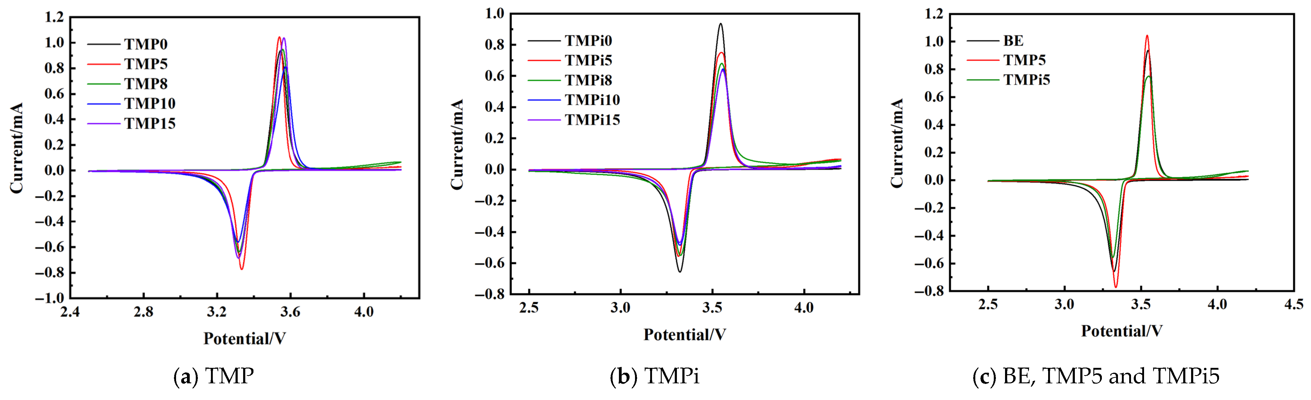
3.2.1. Cyclic Voltammetry Testing of LiFePO4|Li Half-Cells

The cyclic voltammetry of LiFePO4|Li half-cells with different ratios of TMP and TMPi added were tested, as shown in Figure 4 and Table 5.
After adding flame retardant TMP, the following results were found. (1) The CV curves of LiFePO4|Li half-cells with different volume ratios of TMP showed a pair of redox peaks corresponding to Li+ insertion and deinsertion in the voltage range of 2.5~4.2 V, and no new oxidation or reduction peaks appeared, indicating that adding TMP to the LiFePO4|Li half-cell electrolyte does not cause obvious side reactions in the battery system. (2) Compared with the basic electrolyte, the peak currents of the oxidation peak and reduction peak of the electrolyte with TMP added increased, and the peak potential difference decreased, indicating that TMP reduced the electrode polarization degree of the half-cell and improved the electrochemical stability of the electrolyte. (3) When the volume ratio of TMP added was 5%, the peak potential difference was the smallest, the peak current was the largest, and the symmetry of the redox peak was relatively good. Preliminary analysis showed that the addition of TMP may be conducive to the formation of a more stable CEI (solid electrolyte interface) film on the positive electrode surface. The CEI film not only inhibited the reaction between the electrolyte and the electrode but also allowed more lithium ions to participate in the reversible cycle reaction.
After adding the flame retardant TMPi, (1) the CV curves of the LiFePO4|Li half-cells with different volume ratios of TMPi showed a pair of redox peaks corresponding to Li+ insertion and extraction in the voltage range of 2.5–4.2 V, and no obvious side reactions occurred in the entire battery system. (2) With the increase in the TMPi addition ratio, the peak currents of the oxidation peak and the reduction peak first increased and then decreased, and the peak potential difference gradually increased, indicating that the addition of TMPi affected the number of Li+ ions inserted and extracted, increased the polarization of the battery, and reduced the reversibility. (3) When the volume ratio of TMPi addition was 5%, the potential difference between the peak potentials was relatively small, and the symmetry of the redox peaks was relatively good.
When the addition ratio of TMP and TMPi was 5%, the peak currents of the oxidation peak and the reduction peak were TMP, BE, and TMPi from high to low, and the peak potential difference between the oxidation peak and the reduction peak increased in sequence: 0.205 V→0.222 V→0.223 V. Therefore, TMP improved the electrochemical performance of the LiFePO4|Li battery to a certain extent, while TMPi reduced the electrochemical performance of the LiFePO4|Li battery [17].

3.2.2. Discharge Specific Capacity of LiFePO4|Li Half-Cells

The discharge specific capacities of the LiFePO4|Li half-cell with different volume ratios of TMP and TMPi added were tested, and the results are shown in Figure 5 and Table 6.
At 1C current, for the LiFePO4|Li half-cell using the TMP flame-retardant electrolyte, after 300 cycles, the discharge capacity suddenly increased to the highest value after adding TMP and then gradually decreased. Among them, the half-cell with 5% TMP added had the highest discharge capacity of 181.4 mAh·g−1, and the capacity retention rate was the highest after 300 cycles.
For the LiFePO4|Li half-cell using the TMPi flame-retardant electrolyte, during 300 charge and discharge cycles, compared with the basic electrolyte, the addition of TMPi caused the battery discharge capacity to decrease. The discharge capacity increased in the first 15 cycles, then stabilized, and gradually decayed with the increase in the number of cycles. This may be because the electrolyte was unstable in the first 15 cycles, and the cycle began to stabilize after a complete CEI film was formed on the electrode surface. At the same time, the half-cell with 5% TMPi added had the least decrease in discharge capacity after 300 cycles and had the least negative impact on the battery.
After the first cycle, the discharge specific capacity was TMPi5 < BE < TMP5. After 300 cycles, the discharge specific capacity was still TMPi5 < BE < TMP5, and the capacity retention rate was also TMPi5 < BE < TMP5. TMP5 had a higher discharge specific capacity and capacity retention rate during the 300 charge and discharge processes, showing better cycle performance.

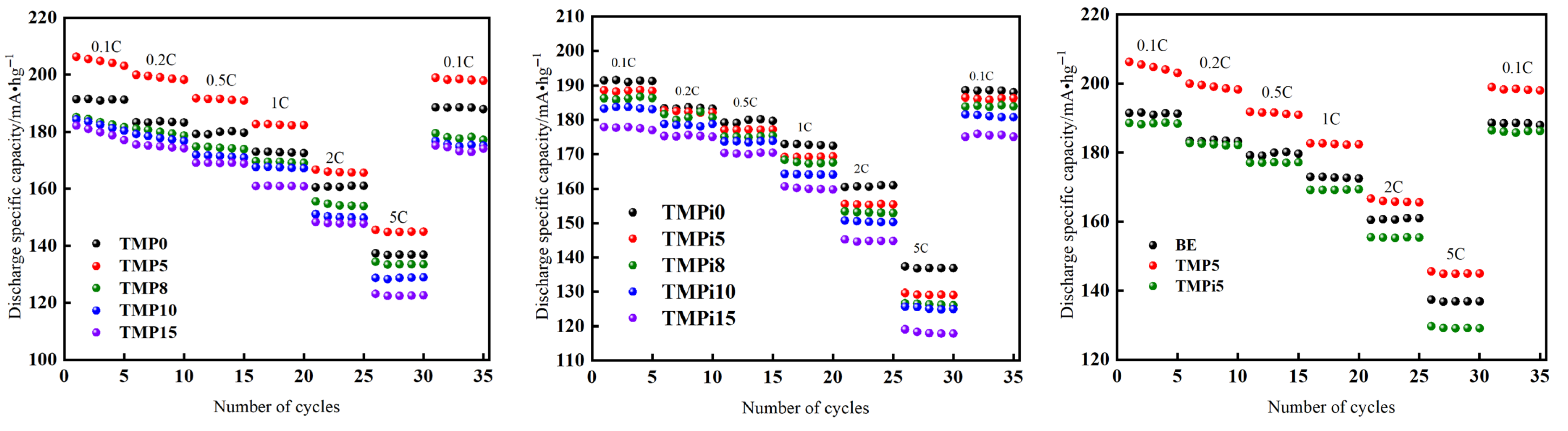
3.2.3. Rate Performance of LiFePO4|Li Half-Cells

The rate performances of LiFePO4|Li half-cells with different ratios of TMP and TMPi were tested, and the results are shown in Figure 6.
When charged and discharged at different current rates of 0.1 C, 0.2 C, 0.5 C, 1 C, 2 C, 5 C, and 0.1 C, the LiFePO4|Li half-cell containing TMP flame-retardant electrolyte with 5% TMP showed a higher discharge specific capacity, and the increase in TMP content did not have a significant negative impact on the rate performance of the battery, which was consistent with the cycle capacity (discharge specific capacity) and CV curve results of the LiFePO4|Li half-cell, indicating that TMP improved the electrochemical performance of the half-cell.
At different current rates, the flame retardant TMPi caused the discharge specific capacity of the LiFePO4|Li battery to decrease, especially at high current rates, and with the increase in TMPi content, the battery’s specific capacity decreased more significantly, among which the addition of 5% TMPi had the least negative impact on the LiFePO4|Li battery.
Based on the above results, at different current rates, TMP5 always showed a higher discharge specific capacity, while TMPi5 caused the discharge specific capacity to decrease, and it was more obvious at high current rates. Therefore, the lithium-ion batteries with the addition of TMP5 exhibited better rate performance due to the reduced polarization.

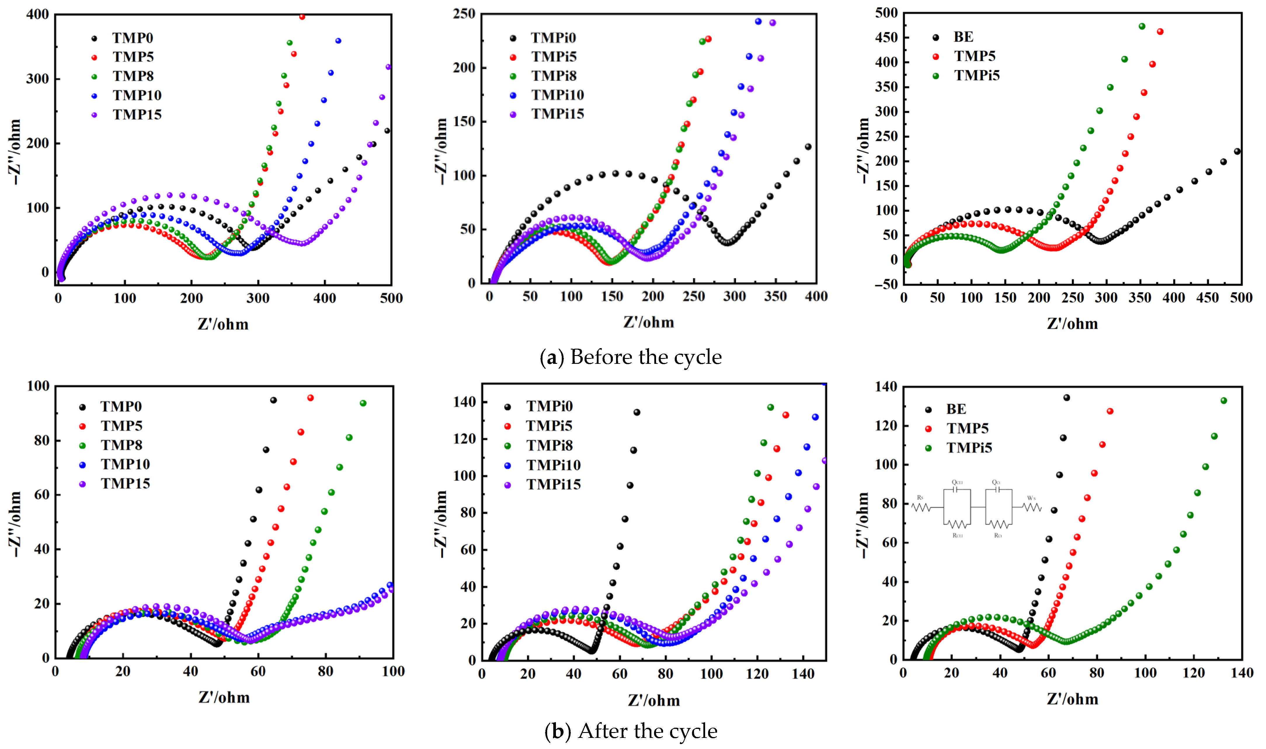
3.2.4. Electrochemical Impedance Spectroscopy of LiFePO4|Li Half-Cells Before and After Cycling

The electrochemical impedance spectra of the LiFePO4|Li half-cells with different volume ratios of TMP and TMPi before and after cycling were tested, respectively. The results and the simulation results of the equivalent circuit diagram are shown in Figure 7. Rs is the ohmic resistance, RCEI and QCEI are the CEI membrane resistance and the double-layer capacitance of the contact interface between the SEI membrane and the electrolyte, Rct and Qct are the charge transfer resistance and double-layer capacitance of the charged particles transferred from the electrode to the electrolyte, and Ws is the diffusion impedance of lithium ions in the solid material. The change of the charge transfer resistance Rct can analyze the stability of the CEI membrane [20,21,22].
Before cycling, that is, after the first activation, compared with the basic electrolyte, the semicircle diameter of the LiFePO4|Li half-cell with 5% TMP and TMPi increased in the high-frequency region, the CEI membrane resistance RCEI increased, the CEI membrane resistance RCEI of 5% TMPi was the largest, the semicircle diameter of the mid-frequency region decreased, the charge transfer resistance Rct decreased, the low-frequency slope decreased, and the lithium ion solid diffusion resistance increased.
After 300 cycles, compared with the basic electrolyte, the semicircle diameter of the high-frequency zone of the LiFePO4|Li half-cell with 5% TMP decreased, the CEI membrane resistance RCEI decreased, and the formed CEI membrane was more stable, while the semicircle diameter of the high-frequency zone of the LiFePO4|Li half-cell with 5% TMPi increased significantly, and the CEI membrane resistance RCEI increased significantly due to membrane damage; the semicircle diameter of the medium-frequency zone of the LiFePO4|Li half-cell with 5% TMP remained almost unchanged, and the charge transfer resistance Rct did not change, while the semicircle diameter of the medium-frequency zone increased with 5% TMPi, and the charge transfer resistance Rct increased. The slopes of the low-frequency zone with the addition of 5% TMP and 5% TMPi both decreased, among which the slope of the low-frequency zone with the addition of 5% TMPi was the smallest, indicating that the addition of TMP and TMPi hindered the diffusion of lithium ions in the solid material, and the hindering effect of TMPi was greater.

3.3. Mechanism of Action

The optimal addition ratio of the flame retardant trimethyl phosphate (TMP) in the LiFePO4|Li battery is 5%, and the optimal addition ratio of trimethyl phosphite (TMPi) in the LiFePO4|Li battery is 5%. Therefore, the volume ratio of 5% was selected to compare and explore the mechanism of action of the phosphorus-containing flame retardants TMP and TMPi with different phosphorus valence states on the performance of lithium-ion batteries.

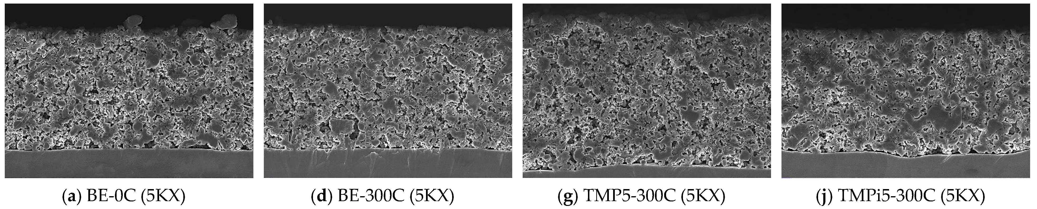
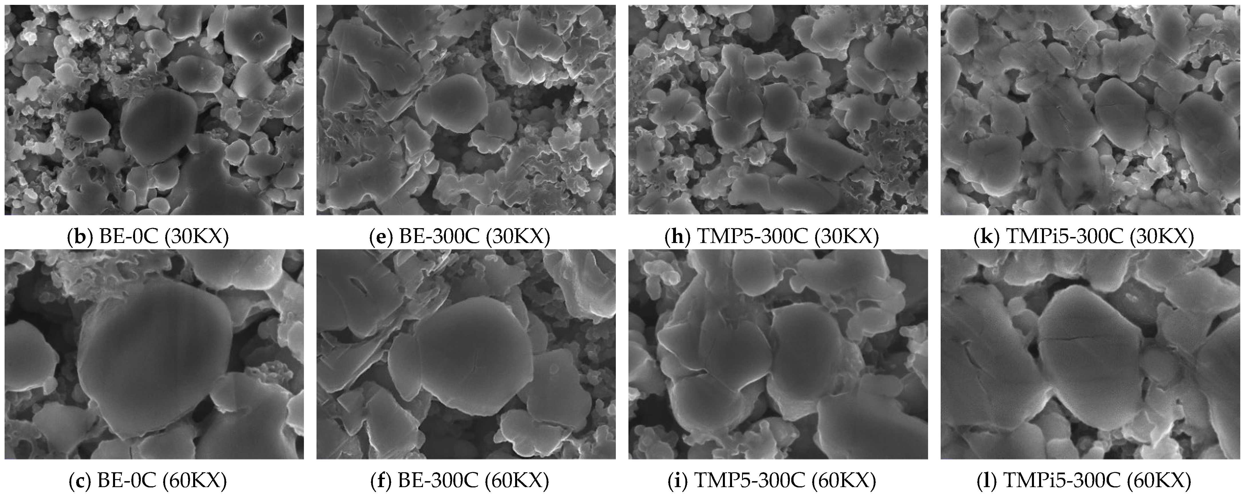
3.3.1. Analysis of Electrode Surface Morphology

The surface morphology and cross-sectional morphology of the LiFePO4|Li half-cell LiFePO4 electrode before and after 300 C cycling were tested, and the results are shown in Figure 8 and Figure 9, respectively. Figure 8a,b show the SEM surface morphologies of the LiFePO4 electrode before cycling with the base electrolyte (BE) at magnifications of 30K and 60K, respectively. Figure 8c,d show the SEM surface morphologies of the LiFePO4 electrode after 300 cycles with BE at magnifications of 30K and 60K, respectively. Figure 8e,f show the SEM surface morphologies of the LiFePO4 electrode after 300 cycles with 5% TMP at magnifications of 30K and 60K, respectively. Figure 8g,h show the SEM surface morphologies of the LiFePO4 electrode after 300 cycles with 5% TMPi at magnifications of 30K and 60K, respectively.
Comparing the surface morphology of the LiFePO4 electrode before and after the basic electrolyte cycle (Figure 8a–d), the surface of the LiFePO4 electrode before the cycle was relatively flat and smooth, without large-area adhesion, cracks or grooves. After 300 cycles, a relatively smooth CEI film was formed on the surface of the LiFePO4 electrode with a small amount of sediment. Further magnification observation showed that some particles of the LiFePO4 electrode have cracks on the surface, which hinder the migration of lithium ions, increases the interface resistance, and causes battery capacity decay.
After adding 5% TMP and cycling for 300 cycles, as shown in Figure 8e,f, the CEI film on the surface of the LiFePO4 electrode was relatively uniform and smooth, without cracks on the surface, indicating that TMP5 was conducive to forming a more uniform and smooth surface on the surface of LiFePO4 electrode. The CEI film protected the electrode and inhibited the decomposition of the solvent on the electrode surface.
After adding 5% TMPi and cycling for 300 cycles, as shown in Figure 8g,h, obvious grooves and cracks appeared on the surface of the LiFePO4 electrode, there were deeper cracks on the particle surface, and the CEI film had cracks and was uneven, which may have exposed more positive electrode materials to the electrolyte, produced side reactions, led to a loss of active substances, and accelerated the decline of battery capacity.
Based on the above analysis, comparing the surface morphology of the LiFePO4 electrode after 300 cycles, adding 5% TMP resulted in a smoother and more uniform CEI film, which was beneficial to the improvement of the battery’s electrochemical performance. Adding 5% TMPi will cause cracks and unevenness in the CEI film on the surface of the LiFePO4 electrode, accelerating the decline of battery capacity.
Figure 9 shows the cross-sectional morphologies of the LiFePO4 electrodes before and after 300 cycles. Figure 9a–c displays the SEM cross-sectional morphologies of the LiFePO4 electrode before cycling with the base electrolyte (BE) at magnifications of 5K, 30K, and 60K, respectively. Figure 9d–f shows the SEM cross-sectional morphologies of the LiFePO4 electrode after 300 cycles with BE at magnifications of 5K, 30K, and 60K, respectively. Figure 9g–i presents the SEM cross-sectional morphologies of the LiFePO4 electrode after 300 cycles with 5% TMP at magnifications of 5K, 30K, and 60K, respectively. Figure 9j–l depicts the SEM cross-sectional morphologies of the LiFePO4 electrode after 300 cycles with 5% TMPi at magnifications of 5K, 30K, and 60K, respectively.
Comparing the cross-sectional morphology of the LiFePO4 electrode before and after the basic electrolyte cycle, the particle distribution of the LiFePO4 electrode cross-sectional view before the cycle was relatively uniform, the particle cross-section was smooth and flat, and there were no cracks. After 300 cycles, the LiFePO4 electrode cross-sectional view showed partial particle collapse, continuous cracks appeared, and obvious cracks appeared on the particle cross-sectional view, indicating that after 300 cycles, the internal structure of the active material particles of the LiFePO4 electrode was destroyed, and some of them fell off and collapsed, which hindered the migration of lithium ions and affected the electrochemical performance of the battery.
The cross-sectional view of the LiFePO4 electrode after 300 cycles with the addition of 5% TMP5 also showed partial collapse, but the cross-sectional view of the active material particles was smoother than that in Figure 9f, with slight cracks, which can slow down the attenuation of the battery capacity.
Based on the above analysis, the cross-sectional view of the LiFePO4 electrode after 300 cycles with the addition of 5% TMPi shows that the active material collapsed severely and stuck together, there were many cracks inside the particles, and the structure was severely damaged, which seriously affected the performance of the LiFePO4 electrode.

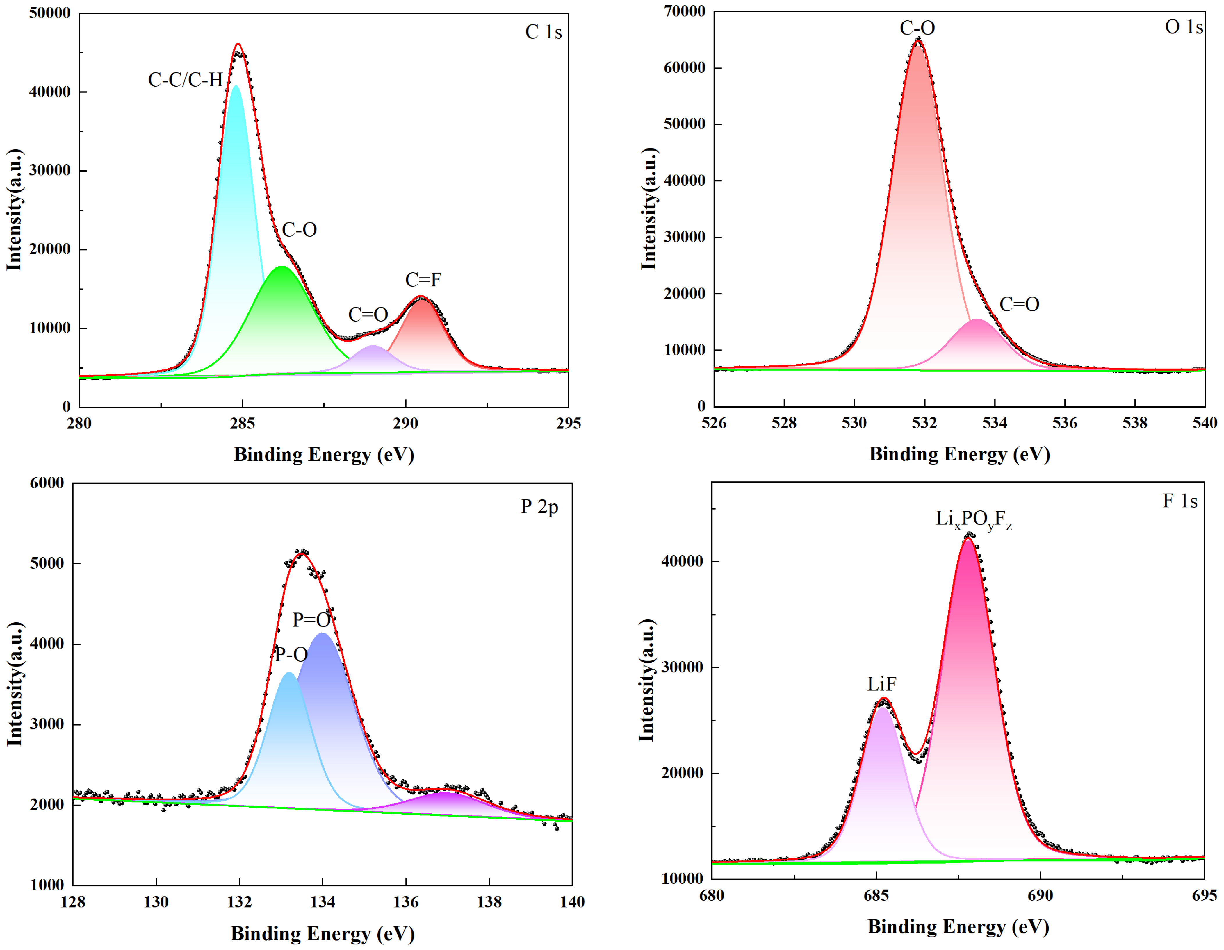
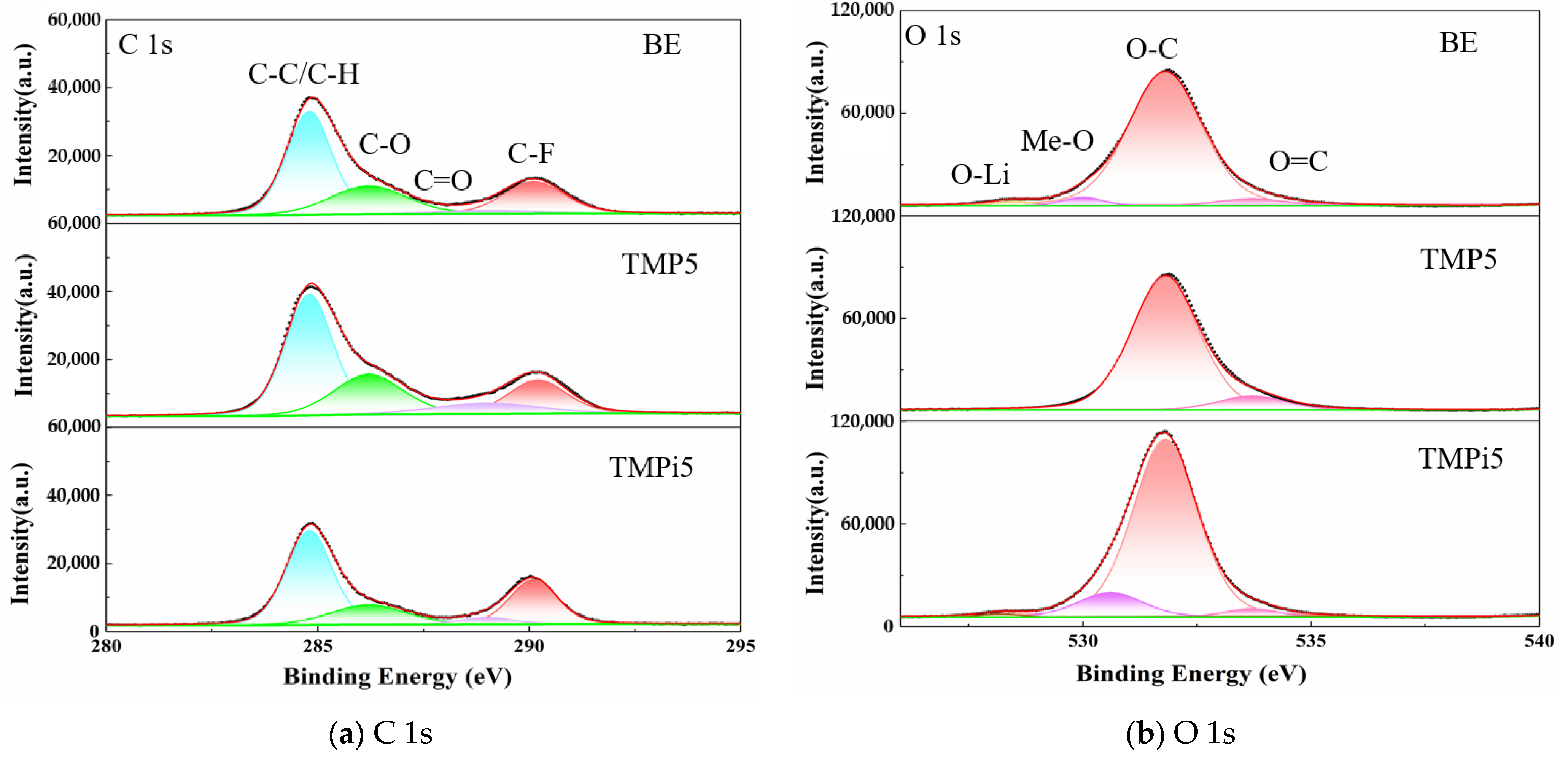
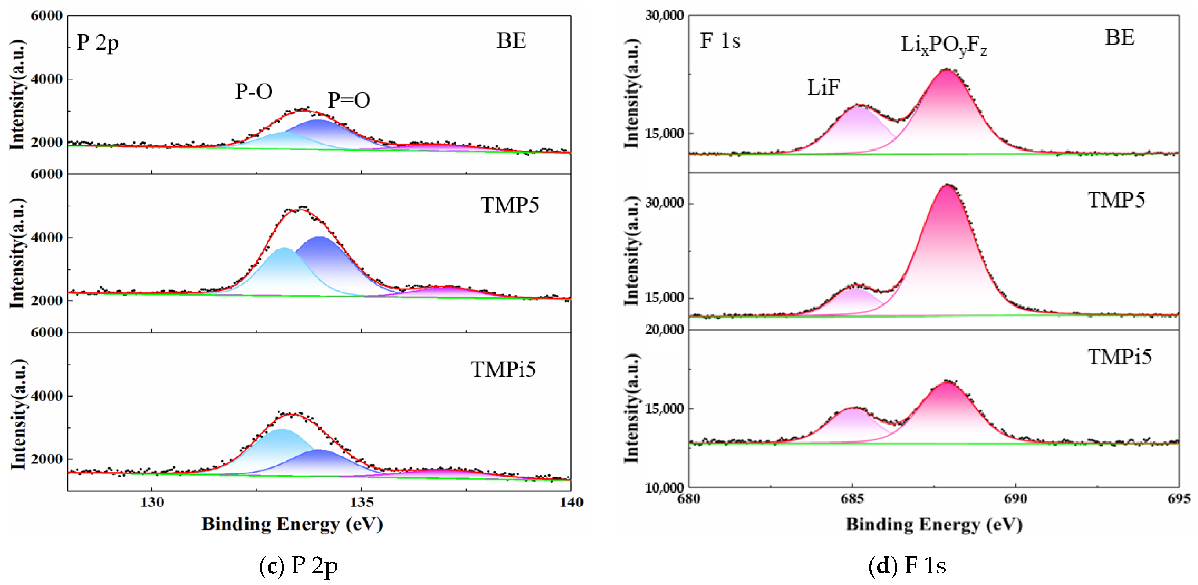
3.3.2. Analysis of Electrode Surface Composition and Elements

To further understand the surface reaction of the LiFePO4 electrode after 300 cycles of TMP5 and TMPi5 batteries, an XPS test was performed on the surface of the LiFePO4 electrode in electrolyte containing TMP5 and TMPi 5 and in the basic electrolyte before and after 300 cycles. The results are shown in Figure 10 and Figure 11.
Compared with the XPS analysis of the LiFePO4 electrode before cycling, the intensities of P and F were both reduced after cycling, as shown in Figure 10 and Figure 11. This demonstrated that after 300 cycles, the contents of P and F were both reduced. In the C 1s spectrum, the carbon elements on the surface of the LiFePO4 electrode existed in the form of C-C, C-O, C=O, C-F, etc., indicating that the organic compound ROCO2Li and the inorganic carbonate Li2CO3 existed in the CEI on the electrode surface [23,24], and C-F may come from polyvinylidene fluoride (PVDF). Compared with the basic electrolyte, after adding TMP5, the content of carbon elements on the surface of the LiFePO4 electrode, such as C-C, C-O, C=O, and C-F, basically did not change, while the C-O on the surface of the LiFePO4 electrode after adding TMPi5 decreased, and C-F increased, indicating that after 300 cycles, the CEI film on the surface of the LiFePO4 electrode with TMPi5 added was unstable, and PVDF was exposed on the electrode surface, resulting in an increase in the C-F content. In the O 1s spectrum, BE and TMPi5 had O-Li, and the methoxy (R-O-Li) content of TMPi5 was higher, while TMP5 did not have R-O-Li, indicating that TMP may inhibit the decomposition of BE to form R-O-Li. In the P 2p and F 1s spectra, phosphorus and fluorine may exist in the form of LixPOyFz, among which the phosphorus (P) and fluorine (F) content on the surface of the LiFePO4 electrode with TMP5 added was higher, which improves the electrochemical integrity of cells [25,26].
Based on the above analysis results, combined with the effects of TMP and TMPi on the performance of LiFePO4|Li batteries, it was speculated that the phosphorus and fluorine components in the smooth and stable CEI film on the electrode surface were helpful in improving the electrochemical performance of LiFePO4|Li batteries.

4. Conclusions

(1) The self-extinguishing time of the electrolytes with 5% TMP and TMPi added is significantly reduced, achieving a flame-retardant effect. Moreover, as the concentration increases, the self-extinguishing time tends to level off. The overall self-extinguishing time of TMP is slightly higher than that of TMPi, and their flame-retardant performances are basically comparable.
(2) Both phosphorus-containing flame retardants TMP and TMPi can reduce the self-extinguishing time of the base electrolyte and enhance its safety. Considering the electrochemical performances of the LiFePO4|Li half-cells, such as CV curves, cycling performance, rate performance, and AC impedance spectra, the most suitable addition ratio for both flame retardants is 5%.
(3) Compared with TMPi5, the LiFePO4|Li half-cell with TMP5 added has a smaller potential difference between the peak potentials of the oxidation and reduction peaks, indicating reduced battery polarization. After 300 cycles, it has a larger discharge specific capacity and a higher capacity retention rate. Additionally, it exhibits larger discharge specific capacities at different current rates and has lower electrode resistance. In contrast, TMPi5 causes a decline in discharge specific capacity, which is more evident at high current rates. Therefore, the LiFePO4|Li half-cell with TMP5 added has better cycling and electrochemical performance.
(4) After 300 cycles, the surface of the LiFePO4 electrode with 5% TMP added has a smoother and more uniform CEI film, which is conducive to enhancing electrochemical performance. The cross-section of the LiFePO4 electrode shows slight collapse and cracks, but the particle interfaces are smoother, slowing down battery capacity decay. On the other hand, adding 5% TMPi results in a CEI film with gaps and unevenness on the surface of the LiFePO4 electrode. The cross-section shows severe collapse of the active material, particles adhering together, numerous cracks, and severe structural damage, accelerating battery capacity decay.
(5) Compared with BE and TMPi5, the surface CEI film of the LiFePO4 electrode with 5% TMP added contains higher phosphorus (P) and fluorine (F) contents, which improve the electrochemical performance of the LiFePO4|Li battery. There is no R-O-Li, and TMP inhibits the decomposition of the base electrolyte.

Author Contributions

Conceptualization, P.X.; methodology, P.X.; validation, P.X.; formal analysis, P.X.; investigation, G.C.; resources, P.X.; data curation, P.X. and F.S.; writing—original draft preparation, P.X. and Z.L.; writing—review and editing, P.X.; visualization, P.X.; project administration, P.X.; funding acquisition, P.X.; supervision, X.F. and X.T.; software, Q.Z. All authors have read and agreed to the published version of the manuscript.

Funding

This research was funded by the Science and Technology Project of Hebei Education Department (BJK2023063) and supported by the Fundamental Research Funds for the Central Universities (Grant No. 3142021001). The work is also supported by the Foundation of Key Laboratory of Power Machinery and Engineering, Ministry of Education, P.R. China (202201).

Data Availability Statement

The data presented in this study are available on request from the corresponding author on request.

Acknowledgments

We would like to thank Q. Zhuo for providing software.

Conflicts of Interest

The authors declare no conflicts of interest.

References

  1. Konarova, M.; Taniguchi, I. Preparation of carbon coated LiFePO4 by a combination of spray pyrolysis with planetary ball-milling followed by heat treatment and their electrochemical properties. Powder Technol. 2009, 191, 111–116. [Google Scholar] [CrossRef]
  2. Kumai, K.; Miyashiro, H.; Kobayashi, Y.; Takei, K.; Ishikawa, R. Gas generation mechanism due to electrolyte decomposition in commercial lithium-ion cell. J. Power Sources 1999, 81, 715–719. [Google Scholar] [CrossRef]
  3. Chen, S.Y.; Wang, Z.X.; Zhao, H.; Qiao, H.; Luan, H.; Chen, L. A novel flame retardant and film-forming electrolyte additive for lithium ion batteries. J. Power Sources 2009, 187, 229–232. [Google Scholar] [CrossRef]
  4. Xia, L.; Xia, Y.G.; Liu, Z.P. A novel fluorocyclophosphazene as bifunctional additive for safer lithium-ion batteries. J. Power Sources 2015, 278, 190–196. [Google Scholar] [CrossRef]
  5. Zhu, X.; Jiang, X.; Ai, X.; Yang, H.; Cao, Y. Bis(2,2,2-Trifluoroethyl) ethylphosphonate as novel high-efficient flame retardant additive for safer lithium-ion battery. Electrochim. Acta 2015, 165, 67–71. [Google Scholar] [CrossRef]
  6. Dunn, R.P.; Nadimpalli, S.P.V.; Guduru, P.; Lucht, B.L. Flame retardant co-solvent in-corporation into lithium-ion coin cells with thin-film Si anodes. J. Electrochem. Soc. 2013, 161, A176–A182. [Google Scholar] [CrossRef]
  7. Gao, D.; Xu, J.B.; Lin, M.; Xu, Q.; Ma, C.F.; Xiang, H.F. Ethylene ethyl phosphate as a multifunctional electrolyte additive for lithium-ion batteries. RSC Adv. 2015, 5, 17566–17571. [Google Scholar] [CrossRef]
  8. Sun, H.; Wei, O. Polyfluorinated electrolyte solutions and additives for high voltage non-flammable lithium batteries. ECS Trans. 2013, 50, 349–354. [Google Scholar] [CrossRef]
  9. Naoi, K.; Iwama, E.; Honda, Y. Discharge behavior and rate performances of lithium-ion batteries in nonflammable hydrofluoroethers (II). J. Electrochem. Soc. 2010, 157, A190. [Google Scholar] [CrossRef]
  10. Nakajima, T.; Dan, K.-I.; Koh, M.; Ino, T.; Shimizu, T. Effect of addition of fluoroethers to organic solvents for lithium ion secondary batteries. J. Fluor. Chem. 2001, 111, 167–174. [Google Scholar] [CrossRef]
  11. Wu, B.; Pei, F.; Wu, Y.; Mao, R.; Ai, X.; Yang, H.; Cao, Y. An electrochemically compatible and flame-retardant electrolyte additive for safe lithium ion batteries. J. Power Sources 2013, 227, 106–110. [Google Scholar] [CrossRef]
  12. Hu, J.; Jin, Z.; Zhong, H.; Zhan, H.; Zhou, Y.; Li, Z. A new phosphonamidate as flame retardant additive in electrolytes for lithium ion batteries. J. Power Sources 2012, 197, 297–300. [Google Scholar] [CrossRef]
  13. Jin, Z.; Gao, H.; Kong, C.; Zhan, H.; Li, Z. A novel phosphate-based flame retardant and film-forming electrolyte additive for lithium ion batteries. ECS Electrochem. Lett. 2013, 2, A66–A68. [Google Scholar] [CrossRef]
  14. Wilken, S.; Xiong, S.; Scheers, J.; Jacobsson, P.; Johansson, P. Ionic liquids in lithium battery electrolytes: Composition versus safety and physical properties. J. Power Sources 2015, 283, 531. [Google Scholar] [CrossRef]
  15. Lombardo, L.; Brutti, S.; Navarra, M.A.; Panero, S.; Reale, P. Mixtures of ionic liquid-alkyl carbonates as electrolytes for safe lithium-ion batteries. J. Power Sources 2013, 227, 8–14. [Google Scholar] [CrossRef]
  16. Wang, X.M.; Yasukawa, E.; Kasuya, S. Nonflammable Trimethyl Phosphate Solvent-Containing Electrolytes for Lithium Ion Batteries: I. Fundamental Properties. J. Electrochem. Soc. 2001, 148, A1058–A1065. [Google Scholar] [CrossRef]
  17. Yan, P. Study on Phosphorus Containing Flame Retardant Additives of Lithium Iron Battery Electrolyte. Master’s Thesis, Nanjing Tech University, Nanjing, China, 2020. [Google Scholar]
  18. Campion, C.L.; Li, W.; Lucht, B.L. Thermal decomposition of LiPF6-based electrolytes for lithium-ion batteries. J. Electrochem. Soc. 2005, 152, 35–42. [Google Scholar] [CrossRef]
  19. Wu, Z.-H.; Huang, A.-C.; Tang, Y.; Yang, Y.-P.; Liu, Y.-C.; Li, Z.-P.; Zhou, H.-L.; Huang, C.-F.; Xing, Z.-X.; Shu, C.-M.; et al. Thermal Effect and Mechanism Analysis of Flame-Retardant Modified Polymer Electrolyte for Lithium-Ion Battery. Polymers 2021, 13, 1675. [Google Scholar] [CrossRef]
  20. Cao, N.; Du, H.; Lu, J.; Li, Z.; Qiang, Q.; Lu, H. Designing ionic liquid electrolytes for a rigid and Li+-conductive solid electrolyte interface in high performance lithium metal batteries. Chem. Phys. Lett. 2025, 866, 141959. [Google Scholar] [CrossRef]
  21. Ahuja, A.; Kumar, A.; Alam, K.; Lohani, H.; Sengupta, A.; Kumari, P.; Thapliyal, K.; Major, D.T.; Mitra, S. Enhancing High-Voltage LNMO Cathode Performance in Li-Metal Batteries Via Anionic Electrolyte Additive-Integrated CEI Engineering. Adv. Funct. Mater. 2025, 35, 2416634. [Google Scholar] [CrossRef]
  22. Tan, C.; Yang, J.; Pan, Q.; Li, Y.; Li, Y.; Cui, L.; Fan, X.; Zheng, F.; Wang, H.; Li, Q. Optimizing interphase structure to enhance electrochemical performance of high voltage LiNi5Mn1.5O4 cathode via anhydride additives. Chem. Eng. J. 2021, 410, 128422. [Google Scholar] [CrossRef]
  23. Liu, J.; Song, X.; Zhou, L.; Wang, S.; Song, W.; Liu, W.; Long, H.; Zhou, L.; Wu, H.; Feng, C.; et al. Fluorinated phosphazene derivative–A promising electrolyte additive for high voltage lithium ion batteries: From electrochemical performance to corrosion mechanism. Nano Energy 2018, 46, 404–414. [Google Scholar] [CrossRef]
  24. Ma, Y.L. Performance Investigation of Electrolyte Containing Flame-Retardants of Phosphate for Lithium Batteries. Ph.D. Thesis, Harbin Institute of Technology, Harbin, China, 2010. [Google Scholar]
  25. Yusuf, A.; Avvaru, V.S.; De la Vega, J.; Zhang, M.; Molleja, J.G.; Wang, D.-Y. Unveiling the structure, chemistry and formation mechanism of an in-situ phosphazene flame retardant-derived interphase layer in LiFePO4 cathode. Chem. Eng. J. 2022, 455, 140678. [Google Scholar] [CrossRef]
  26. Choi, J.; Kang, J.; Kim, C.; Jung, C.; Lee, R.; Park, M.; Park, M. Design Strategies and Performance Enhancement Techniques for LiFePO4-Based Li Metal Battery Systems. Korean J. Chem. Eng. 2025, 42, 1427–1451. [Google Scholar] [CrossRef]
Figure 1. FTIR and XRD spectra for LiFePO4.
Processes 13 02248 g001
Figure 2. Self-extinguishing time of different electrolytes.
Processes 13 02248 g002
Figure 3. DSC of basic electrolyte and electrolytes with 5% TMP and TMPi.
Processes 13 02248 g003
Figure 4. Cyclic voltammetry curve of LiFePO4|Li half-cells with different volume ratios of TMP/TMPi.
Processes 13 02248 g004
Figure 5. Discharge specific capacity of LiFePO4|Li half-cells.
Processes 13 02248 g005
Figure 6. Rate performance of LiFePO4|Li half-cells.
Processes 13 02248 g006
Figure 7. Electrochemical impedance spectroscopy of LiFePO4|Li half-cells before and after 300 cycles.
Processes 13 02248 g007
Figure 8. SEM surface morphology of the LiFePO4 electrode before and after cycling.
Processes 13 02248 g008aProcesses 13 02248 g008b
Figure 9. SEM cross-sectional morphology of the LiFePO4 electrode before and after cycling.
Processes 13 02248 g009aProcesses 13 02248 g009b
Figure 10. XPS analysis of the LiFePO4 electrode before cycling.
Processes 13 02248 g010
Figure 11. XPS analysis of the LiFePO4 electrode after 300 cycles.
Processes 13 02248 g011aProcesses 13 02248 g011b
Table 1. Experimental materials.
Material NameGrade/ModelManufacturer
Argon gasHigh purity/
Lithium iron phosphateBattery gradeShenzhen Tianchenghe Technology Co., Ltd., Shenzhen, China
Acetylene blackBattery gradeShenzhen Tianchenghe Technology Co., Ltd., Shenzhen, China
Polyvinylidene fluoridePVDF5130Guangdong Canrd New Energy Technology Co., Ltd., Dongguan, China
N-methylpyrrolidoneAnalytical gradeTianjin Yongda Chemical Reagent Co., Ltd., Tianjin, China
Trimethyl phosphateAnalytical gradeTianjin Yongda Chemical Reagent Co., Ltd., Tianjin, China
Trimethyl phosphiteAnalytical gradeAdamas Reagent Co., Ltd., Shanghai, China
Electrolyte1 M LiPF6/EC: DMC: EMC (1:1:1 wt.%)Guangdong Canrd New Energy Technology Co., Ltd., Dongguan, China
SeparatorDomestic PPShenzhen Tianchenghe Technology Co., Ltd., Shenzhen, China
Lithium metal sheet/Nanjing Wanqing Chemical Glass Instrument Co., Ltd., Nanjing, China
Aluminum foilBattery gradeShenzhen Tianchenghe Technology Co., Ltd., Shenzhen, China
Copper foilBattery gradeHefei Kejing Materials Technology Co., Ltd., Hefei, China
Ceramic fiber paper1 mm × 0.61 m × 1 m/
Table 2. Composition of electrolyte containing phosphorus flame retardant.
NumberBasic Electrolyte CompositionFlame-Retardant Volume Ratio/%
BE (TMP0/TMPi0)LiPF6 molar concentration: 1.0 mol L−1
EC:DMC:EMC mass ratio = 1:1:1
0
TMP5LiPF6 molar concentration: 1.0 mol L−1
EC:DMC:EMC mass ratio = 1:1:1
5
TMP8LiPF6 molar concentration: 1.0 mol L−1
EC:DMC:EMC mass ratio = 1:1:1
8
TMP10LiPF6 molar concentration: 1.0 mol L−1
EC:DMC:EMC mass ratio = 1:1:1
10
TMP15LiPF6 molar concentration: 1.0 mol L−1
EC:DMC:EMC mass ratio = 1:1:1
15
TMPi5LiPF6 molar concentration: 1.0 mol L−1
EC:DMC:EMC mass ratio = 1:1:1
5
TMPi8LiPF6 molar concentration: 1.0 mol L−1
EC:DMC:EMC mass ratio = 1:1:1
8
TMPi10LiPF6 molar concentration: 1.0 mol L−1
EC:DMC:EMC mass ratio = 1:1:1
10
TMPi15LiPF6 molar concentration: 1.0 mol L−1
EC:DMC:EMC mass ratio = 1:1:1
15
Table 3. Self-extinguishing time of basic electrolyte and electrolytes with different ratios of TMP and TMPi.
Electrolytem1/gm2/gt/sm1−m2SET/s g−1Average Value of SET/s g−1
BE22.5521.9130.760.6448.06346.67
21.2133.500.7047.859
20.5329.980.6844.088
TMP528.4827.8018.690.6827.48527.925
27.1418.720.6628.364
26.5317.030.6127.926
TMP829.5428.9215.180.6224.48426.472
28.3116.810.6127.557
27.6717.520.6427.375
TMP1030.7430.0916.780.6525.81525.078
29.3917.40.7024.857
28.7515.720.6424.563
TMP1530.5629.9115.470.6523.823.637
29.2615.280.6523.508
28.6813.690.5823.603
TMPi522.6722.0617.540.6128.75428.795
21.4417.730.6228.60
20.818.580.6429.031
TMPi822.9422.2715.850.6723.67123.43
21.6214.940.6522.985
20.9316.310.6923.638
TMPi1023.4522.7516.280.7023.25723.16
22.0815.570.6723.239
21.4314.940.6522.985
TMPi1524.1623.5114.940.6522.98523.01
22.8714.650.6422.891
22.1915.740.6823.147
Table 4. Differential scanning calorimetry results of basic electrolyte and electrolytes with 5% TMP and TMPi.
ElectrolyteInitial Reaction Temperature/°CThe First Peak Temperature/°CThe Second Peak Temperature/°CThe Total Heat Absorbed J g−1
BE96.8119.96270.79398.2
TMP594.87121.56259.61357.7
TMPi5110.90111.53259.69389.8
Table 5. Peak potential differences between redox peaks of LiFePO4|Li half-cells with different volume ratios of TMP/TMPi.
Electrolyte SolutionOxidation Peak Potential/VReduction Peak Potential/VPeak Potential Difference/V
TMP0 (BE)3.5453.3230.222
TMP53.5393.3340.205
TMP83.5573.320.237
TMP103.5723.3130.259
TMP153.5633.3160.247
TMPi0 (BE)3.5453.3230.222
TMPi53.5513.3280.223
TMPi83.5513.3260.225
TMPi103.5623.3320.230
TMPi153.5553.3220.233
Table 6. Discharge specific capacity of LiFePO4|Li half-cells containing TMP and TMPi.
LiFePO4|Li Half-Cell Containing TMP and TMPiDischarge Specific Capacity After the First Cycle/mAh g−1Discharge Specific Capacity After 300 Cycles/mAh g−1Capacity Retention Rate/%
TMPi0 (BE)180.7175.297.0
TMP5182.3181.499.5
TMP8183.3173.994.9
TMP10189.6172.791.1
TMP15182.3162.992.8
TMPi0 (BE)180.7175.297.0
TMPi 5174.7168.296.3
TMPi 8163.2165.8101.6
TMPi 10160.2161.0100.5
TMPi 15157.8147.093.2
Disclaimer/Publisher’s Note: The statements, opinions and data contained in all publications are solely those of the individual author(s) and contributor(s) and not of MDPI and/or the editor(s). MDPI and/or the editor(s) disclaim responsibility for any injury to people or property resulting from any ideas, methods, instructions or products referred to in the content.

