
Kinematic Analysis of the Jaw Crusher Drive Mechanism: A Different Mathematical Approach

 ,
,  ,
,  ,
,  ,
,  , ,
, , 
Abstract
1. Introduction
- The material is introduced between two jaws, one fixed and one movable.
- Through the oscillatory motion of the movable jaw, the distance between the two jaws decreases, generating compressive forces on the material, which leads to its crushing and fragmentation.
- Kinematic and dynamic analysis: Modeling the motion of the jaws and the double-toggle mechanism has enabled a deeper understanding of force distribution and particle trajectories during the crushing process. Mathematical methods and finite element simulations (FEM) have been employed to optimize geometry and reduce mechanical stresses [1,10,11,12,13,14,15,16,17,18,19,20,21].
- Optimization of operating parameters: Experimental studies have highlighted the influence of the nip angle, stroke of the movable jaw, and rotational speed on crushing efficiency, demonstrating that adjusting these parameters can lead to increased throughput and reduced energy consumption [13,18,22,23,24,25,26,27].
- Automation and intelligent monitoring: The integration of vibration, temperature, and pressure sensors has enabled the development of real-time monitoring systems, contributing to fault prevention and the optimization of predictive maintenance strategies [36].
2. Working Methodology
- -
- The mechanism under investigation was presented, with the following identified:
- ○
- The fixed and moving elements, corresponding to the fixed and movable kinematic pairs of the analyzed mechanism;
- ○
- Dimensional values were assigned to the elements that establish the connections between the kinematic pairs.
- -
- Based on this mechanism, a set of mathematical relationships was developed, derived from the principles of planar kinematics, with the aim of describing the motion generated by the system.
- -
- A series of technical specifications corresponding to the structural components of a double-toggle jaw crusher were identified from the specialized literature. From these, a reference configuration was selected to enable subsequent numerical comparisons.
- -
- For the numerical computation, a software tool capable of handling calculations for multiple input values was required; therefore, Mathcad 15 was selected for this purpose.
- -
- To validate the mathematical relationships used, an analysis was also performed using three distinct software applications developed by different manufacturers.
- -
- The values obtained through mathematical computation were compared with the data generated by the three simulation tools.
3. Theoretical Considerations
- Group 1 consists of the driving element AB, i.e., the crank. Within this group, the coordinates of joint B can be determined;
- Group 2 may consist of elements AB and BC or, alternatively, of elements DC and BC. Regardless of the chosen configuration, this group allows for the determination of the coordinates of joint C;
- Group 3 can also be formed in two ways: the first variant includes elements BC and CE, while the second includes elements FE and EC. In both cases, the objective is to determine the coordinates of joint E.
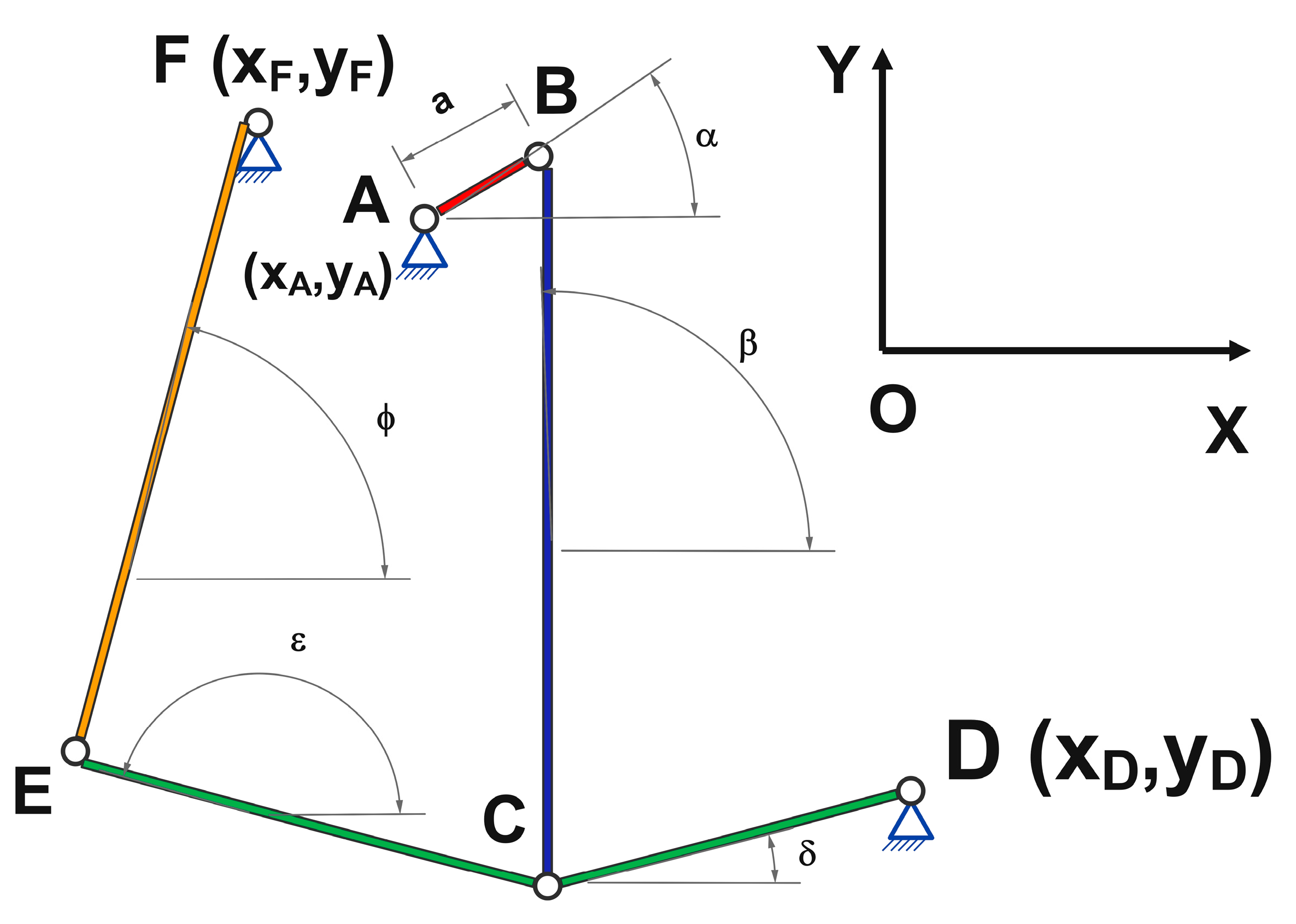
- Each element of the mechanism is assigned a dimensional value;
- The rotating element is identified, and its motion is represented by the rotation angle of the crank, denoted as α.
- Joint A—xA and yA;
- Joint D—xD and yD;
- Joint F—xF and yF.
- The equations corresponding to joint B are given by the following expressions:
- The calculation relationships corresponding to joint C can be determined using the following equations:
- The calculation relationships required to determine the coordinates of joint E are
- -
- Angle β represents the angle formed by element BC with respect to the horizontal axis;
- -
- Angle δ represents the angle formed by element CD with respect to the horizontal axis;
- -
- Angle ε represents the angle formed by element CE with respect to the horizontal axis;
- -
- Angle ϕ represents the angle formed by element EF with respect to the horizontal axis.
- For angle β:
- For angle δ:
- For angle ε:
- For angle ϕ:
- -
- Regardless of which component is being analyzed (calculation relationships for the coordinates of couples B, C, or E, or angles β, δ, ε, and ϕ), their values are closely related to the variation in angle α;
- -
- Regarding the calculation relationships corresponding to the studied joints,
- ○
- The motion of joint C depends on the positions of the fixed joints A and D, the dimensional values of elements AB, BC, and CD, and the angle formed by the crank AB with respect to the horizontal axis;
- ○
- The motion of joint E depends on the position of the fixed joint F, the position of the moving joint C, and the dimensional values of elements EF and EC;
- ○
- As a result of this analysis, it can be stated that, in order to determine the coordinates of joints C and E, the mechanism can be divided into two subsystems:
- ▪
- For joint C, it is necessary to know the characteristics of the four-bar linkage formed by elements AB, BC, and CD;
- ▪
- For joint E, it is necessary to know the characteristics of the mechanism formed by elements EF and EC.
- -
- Regarding the calculation relationships corresponding to the analyzed angles,
- ○
- Angle β depends on the coordinates of the fixed joint A, the coordinates of the moving joint C, the dimensional value of the crank, and the angle it forms with the horizontal axis;
- ○
- Angle δ depends only on the coordinates of the fixed joint D and the moving joint C;
- ○
- Both angles ε and ϕ depend on the coordinates of the fixed joint F, the coordinates of the moving joint C, and the dimensional values of elements EF and EC.
4. Results
- -
- Dimensions of the elements in the crusher’s actuation system:
- ○
- Element AB = 42 mm.
- ○
- Element BC = 2165 mm.
- ○
- Element DC = 1099 mm.
- ○
- Element CD = 1839 mm.
- ○
- Element FE = 2885 mm.
- -
- Coordinates of the fixed joints:
- ○
- Fixed joint A has the coordinates xA = 0 mm, yA = 0 mm;
- ○
- Fixed joint D has the coordinates xD = 1190 mm, yD = −1800 mm;
- ○
- Fixed joint F has the coordinates xF = −1625 mm, yF = 1011 mm.
- -
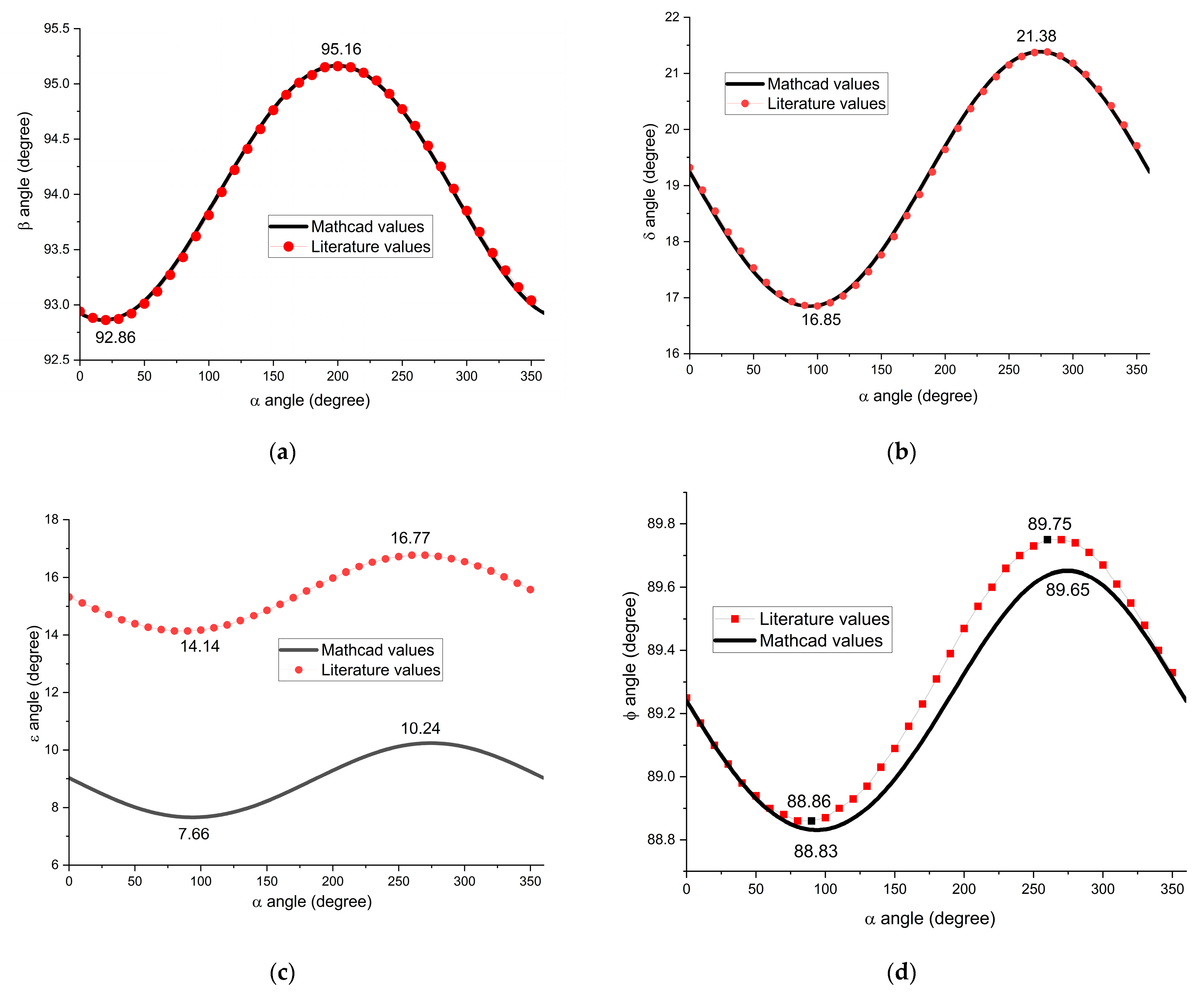
- Regarding the variation in angles β and δ, which correspond to the angles formed by elements BC and CD with respect to the horizontal axis, it can be stated that they match the values found in the specialized literature both in terms of magnitude and variation pattern (a sinusoidal trend is observed). Numerically, angle β varies between approximately 92.86° and 95.16°, indicating a relatively small but kinematically significant oscillation. As for angle δ, it varies between 16.85° and 21.38°.
- -
- Regarding the variation in angle ε, it is observed that its values differ from those found in the specialized literature by approximately 6°. These differences may be caused by errors in measuring the angular value or even in the construction of the mechanism (failure to observe the position of point E may lead to this difference—the reference article [48] does not specify the exact position of coupling E). However, the variation pattern of angle ε with respect to the crank angle α remains consistent. The variation range of angle ε, as obtained using Mathcad, is between a minimum of 7.66° and a maximum of 10.24°.
- -
- Concerning the variation in angle ϕ, it is noted that for the crank angle intervals 0–55° and 325–360°, there are no differences between the mathematically obtained values and those reported in the literature. Outside these intervals, a maximum deviation of 0.14° is observed between the two data sets. Additionally, angle ϕ varies within a very narrow range, from 88.8° to 89.65°, indicating a limited oscillation, which is a result of the constrained motion within the mechanism.
- -
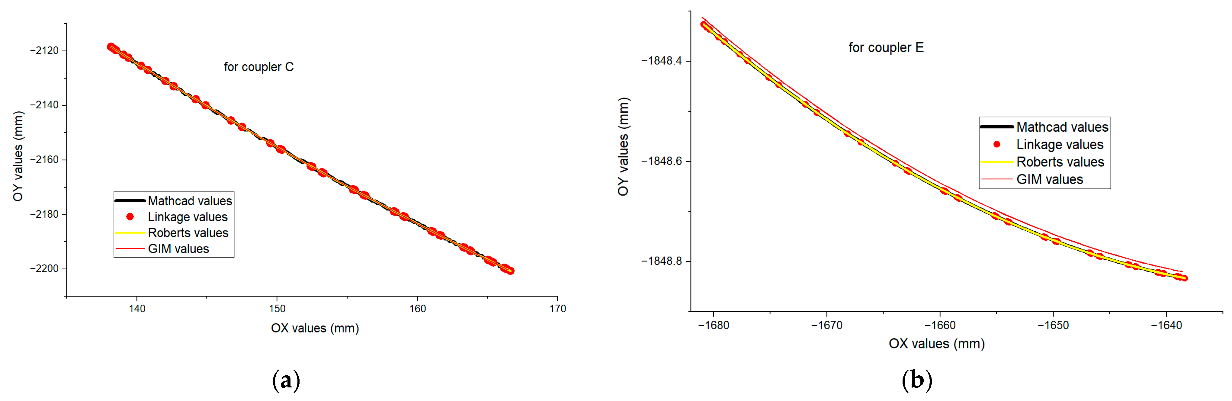
- Regarding the trajectory of the C pair, the graph demonstrates a high degree of consistency among the results obtained from the four different motion analysis sources. This coherence validates the identified mathematical model used for analyzing the motion of point C.
- -
- Regarding the trajectory of the E pair, it is observed that all four curves follow a similar path, indicating good agreement between the applied methods. A minor discrepancy of 0.013 mm is noted between the values obtained using Mathcad, Linkage, and Roberts Animator, compared to those obtained via GIM software. This variation may be attributed to the interpolation algorithms employed by the respective programs.
- -
- Regarding the variation in the linear velocity corresponding to the C pair, the range of variation is between 0.95 and 274 mm/s;
- -
- For the linear velocity variation in the E pair, it follows a similar pattern to that of the C pair but with a smaller range between 0.4 and 135 mm/s;
- -
- Regardless of the pair under analysis, the linear velocity variation exhibits a sinusoidal profile;
- -
- Both pairs show fluctuations in linear velocity, with the parameter reaching a minimum after an interval of 0.5 s, indicating that the mechanism under study performs a cyclic motion;
- -
- The fact that all applied methods, the mathematical calculation method presented in this paper and the motion simulation methods using the three software tools, yield similar results, validates the proposed model.
5. Conclusions
Author Contributions
Funding
Data Availability Statement
Conflicts of Interest
References
- Kwaśniewski, A.; Ciężkowski, P. Selected design issues of toggle plate selection on the example of the single jaw crusher. Mach. Dyn. Res. 2017, 41, 17–30. [Google Scholar]
- Neikov, O.D. Chapter 2—Mechanical Crushing and Grinding. In Handbook of Non-Ferrous Metal Powders, 2nd ed.; Neikov, O.D., Naboychenko, S.S., Yefimov, N.A., Eds.; Elsevier: Oxford, UK, 2019; pp. 65–90. [Google Scholar]
- Shokhin, A.E. Self-Synchronization of a Vibrating Jaw Crusher with Allowance for Interaction with the Medium Processed. J. Mach. Manuf. Reliab. 2020, 49, 500–510. [Google Scholar] [CrossRef]
- Gaesenngwe, G.; Gwiranai, D.; Shephered, B. Assessing Efficiency in a unified size reduction plant when reducing large ore into powder particulate matter. Procedia Manuf. 2019, 35, 808–813. [Google Scholar] [CrossRef]
- Certified MTP. Certified Material Testing Products. Jaw Crusher: What Type Is Best for Primary Crushing? Available online: https://blog.certifiedmtp.com/what-type-of-jaw-crusher-is-best-for-primary-crushing/ (accessed on 2 June 2025).
- Shrivastava, A.K.; Sharma, A.K. A review on study of jaw crusher. Int. J. Mod. Eng. Res. 2012, 2, 885–888. [Google Scholar]
- Okechukwu, C.; Dahunsi, O.A.; Oke, P.K.; Oladele, I.O.; Dauda, M.; Olaleye, B.M. Design and operations challenges of a single toggle jaw crusher: A review. Niger. J. Technol. 2017, 36, 814–821. [Google Scholar] [CrossRef]
- Bogdanovská, G.; Benková, M.; Bednárová, D. Analysis of causes and consequences of failures in process of andesite crushing by jaw crusher. Processes 2025, 13, 225. [Google Scholar] [CrossRef]
- Fuzhen, Y. Jaw Crusher. In The ECPH Encyclopedia of Mining and Metallurgy; Kuangdi, X., Ed.; Springer Nature: Singapore, 2024; pp. 982–985. [Google Scholar]
- Moses, O.F. Mechanical Design of a Small Scale Mechanized Stone Crusher. Available online: https://mechanical.uonbi.ac.ke/sites/default/files/cae/engineering/mechanical/Small%20scale%20mechanized%20stone%20crusher,%20Mechanical%20design.pdf (accessed on 2 June 2025).
- Murithi, M.; Keraita, J.N.; Obiko, J.O.; Mwema, F.M.; Wambua, J.M.; Jen, T.C. Optimisation of the swinging jaw design for a single toggle jaw crusher using finite element analysis. Int. J. Interact. Des. Manuf. 2024, 18, 6351–6358. [Google Scholar] [CrossRef]
- Wang, S.P.; Cui, Y.; Wang, C.E. Dynamics Analysis and Chaos Identification of Compound Pendulum Jaw Crusher with Joint Clearance. Appl. Sci. 2023, 13, 238. [Google Scholar] [CrossRef]
- Golikov, N.S.; Timofeev, I.P. Determination of capacity of single-toggle jaw crusher, taking into account parameters of kinematics of its working mechanism. Int. Conf. Inf. Technol. Bus. Ind. 2018, 1015, 052008. [Google Scholar] [CrossRef]
- Kemper, D.; Fimbinger, E.; Antretter, T.; Egger, M.; Flachberger, H. Impact crusher kinematics: The dynamics of an impact swing mechanism as an analytical-mathematical model. Results Eng. 2024, 21, 101694. [Google Scholar] [CrossRef]
- Santhi, R.; Venkatesh, K. Finite element analysis and optimization of swing jaw plate of a jaw crusher. Int. J. Sci. Adv. Res. Technol. 2018, 4, 1034–1039. [Google Scholar]
- Hroncová, D.; Delyova, I.; Frankovský, P.; Neumann, V.; Čech, D. Kinematic motion analysis of the members of a double jaw crusher. Acta Mechatronica 2022, 7, 1–7. [Google Scholar] [CrossRef]
- Oduori, M.F.; Munyasi, D.M.; Mutuli, S.M. Analysis of the Single Toggle Jaw Crusher Force Transmission Characteristics. J. Eng. 2016, 2016, 1578342. [Google Scholar] [CrossRef]
- Altshul, G.M.; Gouskov, A.M.; Panovko, G.Y. Modeling of the interaction between a rock being processed and a vibratory jaw crusher. J. Mach. Manuf. Reliab. 2021, 50, 26–33. [Google Scholar] [CrossRef]
- Oduori, M.F.; Mutuli, S.M.; Munyasi, D.M. The kinematics and mechanical advantage of the double-toggle jaw crusher. Proc. Inst. Mech. Eng. Part C J. Mech. Eng. Sci. 2018, 232, 3325–3336. [Google Scholar] [CrossRef]
- Eddie, G.-H.; Ahmed, S.; Semaan, A. Design and modeling of a six-bar mechanism for repetitive tasks with symmetrical end effector motion. Eng. Technol. Appl. Sci. Res. 2024, 14, 16302–16310. [Google Scholar]
- Figliolini, G.; Lanni, C.; Tomassi, L. First- and Second-Order Centrodes of Both Coupler Links of Stephenson III Six-Bar Mechanisms. Machines 2025, 13, 93. [Google Scholar] [CrossRef]
- Ciężkowski, P.; Maciejewski, J.; Bąk, S.; Kwaśniewski, A. Application of The New Shape Crushing Plate in Machine Crushing Processes. Stud. Geotech. Mech. 2020, 42, 83–96. [Google Scholar] [CrossRef]
- Sinha, R.S.; Mukhopadhyay, A.K. Failure rate analysis of Jaw Crusher: A case study. Sadhana 2019, 44, 17. [Google Scholar] [CrossRef]
- Zhong, X.Q.; Niu, X.J.; Ji, Q.Q.; Shen, X.G. Optimization design and simulation analysis for cavity shape of single toggle jaw crusher. J. Phys. Conf. Ser. 2020, 1622, 012023. [Google Scholar] [CrossRef]
- Luo, Z.H.; Li, S.H. Optimization design for crushing mechanism of double toggle jaw crusher. Appl. Mech. Mater. 2012, 201–202, 312–316. [Google Scholar] [CrossRef]
- Wang, Y.; Lv, K.; Chen, Z. The optimization of jaw crusher with complex motion aimed at reducing stroke feature value of its outlet. Int. J. Eng. Tech. Res. 2018, 8, 390–394. [Google Scholar]
- Zhong, X.; Niu, X.; Ji, Q.; Shen, X. Simulation analysis of cavity shape of compound pendulum jaw crusher. J. Phys. Conf. Ser. 2020, 1637, 012130. [Google Scholar] [CrossRef]
- Olawale, J.O.; Ibitoye, S.A.; Shittu, M.D. Workhardening Behaviour and Microstructural Analysis of Failed Austenitic Manganese Steel Crusher Jaws. Mater. Res. 2013, 16, 1274–1281. [Google Scholar] [CrossRef]
- Machado, P.C.; Pereira, J.I.; Sinatora, A. Abrasion wear of austenitic manganese steels via jaw crusher test. Wear 2021, 476, 203726. [Google Scholar] [CrossRef]
- Chen, Y.H.; Zhang, G.S.; Zhang, R.L.; Gupta, T.; Katayama, A. Finite element study on the wear performance of movable jaw plates of jaw crushers after a symmetrical laser cladding path. Symmetry 2020, 12, 1126. [Google Scholar] [CrossRef]
- Tufan, B.; Tufan, E. Evaluating the impacts of jaw crusher design parameters by simulation. In Proceedings of the ICASET-18, Paris, France, 20–21 June 2018. [Google Scholar]
- Ömer, A.; Metin, M.; Yaghmur, A. Improvement of jaw crusher design by DEM & FEA approach. Int. J. Mech. Eng. 2022, 7, 6211–6220. [Google Scholar]
- Xiong, Y.; Gan, J.; Chen, W.; Ou, T.; Zhao, G.; Wu, D. Application of Multibody Dynamics and Bonded-Particle GPU Discrete Element Method in Modelling of a Gyratory Crusher. Minerals 2024, 14, 774. [Google Scholar] [CrossRef]
- Rishmany, J.; Imad, R. Finite Element and Multibody Dynamics Analysis of a Ball Mill Glass Crusher. Model. Simul. Eng. 2023, 2023, 1–17. [Google Scholar] [CrossRef]
- Yang, Z.; Zhang, K.; Zhang, Y.; An, J. Discrete Element Method–Multibody Dynamics Coupling Simulation and Experiment of Rotary Tillage and Ridging Process for Chili Pepper Cultivation. Agronomy 2024, 14, 446. [Google Scholar] [CrossRef]
- Nedeljković, M.; Kamat, A.; Holthuizen, P.; Tošić, N.; Schlangen, E.; Fennis, S. Energy consumption of a laboratory jaw crusher during normal and high strength concrete recycling. Min. Eng. 2023, 204, 108421. [Google Scholar] [CrossRef]
- 911 Metallurgist. Difference Between Single & Double Toggle Jaw Crusher. Available online: https://www.911metallurgist.com/blog/difference-between-single-double-toggle-jaw-crusher/ (accessed on 2 June 2025).
- Han, Y.X.; Liu, L.; Yuan, Z.T.; Wang, Z.H.; Zhang, P. Comparison of low-grade hematite product characteristics in a high-pressure grinding roller and jaw crusher. Min. Met. Proc. 2012, 29, 75–80. [Google Scholar] [CrossRef]
- Frank, O.M.; Mwenje, M.S.; Masinde, M.D. Analysis of the single toggle jaw crusher kinematics. J. Eng. Des. Technol. 2015, 13, 213–239. [Google Scholar] [CrossRef]
- Nikitin, A.G.; Tagiltsev-Galeta, K.V.; Laktionov, S.A. Comparison of typical control laws of crushing unit on the example of a jaw crusher. IOP Conf. Ser. Earth Environ. Sci. 2019, 377, 012019. [Google Scholar] [CrossRef]
- Paweł, C.; Jan, M.; Sebastian, B. Analysis of energy consumption of crushing processes—Comparation of one-stage and two-stage processes. Stud. Geotech. Mech. 2017, 39, 17–24. [Google Scholar]
- Paweł, C. Correlation of energy consumption and shape of crushing plates. J. Min. Geoengin. 2012, 2012, 91–100. [Google Scholar]
- Ndungu, M.P. Optimisation of Energy Efficiency and Comminution Process of a Single Toggle Jaw Crusher Using Discrete Element Method. Ph.D. Thesis, Jomo Kenyatta University of Agriculture and Technology, Juja, Kenya, 2021. [Google Scholar]
- David, R. Linkage Program. Available online: https://blog.rectorsquid.com/category/programming/linkage-program/ (accessed on 30 May 2025).
- Technologies, H. Roberts Animator. Available online: http://www.aes.nu/1-5softprod.htm (accessed on 30 May 2025).
- Macho, E.; Urízar, M.; Petuya, V.; Hernández, A. Improving Skills in Mechanism and Machine Science Using GIM Software. Appl. Sci. 2021, 11, 7850. [Google Scholar] [CrossRef]
- Petuya, V.; Macho, E.; Altuzarra, O.; Pinto, C.; Hernandez, A. Educational software tools for the kinematic analysis of mechanisms. Comput. Appl. Eng. Educ. 2014, 22, 72–86. [Google Scholar] [CrossRef]
- Mishchuk, Y.; Mishchuk, D.; Kapusta, O. Mathematical modeling kinematics of double toggle jaw crusher. Girnichi Budivelni Dorozhni Meliorativni Mashini 2023, 102, 5–16. [Google Scholar] [CrossRef]


Disclaimer/Publisher’s Note: The statements, opinions and data contained in all publications are solely those of the individual author(s) and contributor(s) and not of MDPI and/or the editor(s). MDPI and/or the editor(s) disclaim responsibility for any injury to people or property resulting from any ideas, methods, instructions or products referred to in the content. |
© 2025 by the authors. Licensee MDPI, Basel, Switzerland. This article is an open access article distributed under the terms and conditions of the Creative Commons Attribution (CC BY) license (https://creativecommons.org/licenses/by/4.0/).
Share and Cite
Mosnegutu, E.; Barsan, N.; Chitimus, D.; Ciubotariu, V.; Bibire, L.; Mirilă, D.; Jasiński, M.; Sporea, N.; Petre, I.C. Kinematic Analysis of the Jaw Crusher Drive Mechanism: A Different Mathematical Approach. Processes 2025, 13, 2226. https://doi.org/10.3390/pr13072226
Mosnegutu E, Barsan N, Chitimus D, Ciubotariu V, Bibire L, Mirilă D, Jasiński M, Sporea N, Petre IC. Kinematic Analysis of the Jaw Crusher Drive Mechanism: A Different Mathematical Approach. Processes. 2025; 13(7):2226. https://doi.org/10.3390/pr13072226
Chicago/Turabian StyleMosnegutu, Emilian, Narcis Barsan, Dana Chitimus, Vlad Ciubotariu, Luminita Bibire, Diana Mirilă, Marcin Jasiński, Nicoleta Sporea, and Ivona Camelia Petre. 2025. "Kinematic Analysis of the Jaw Crusher Drive Mechanism: A Different Mathematical Approach" Processes 13, no. 7: 2226. https://doi.org/10.3390/pr13072226
APA StyleMosnegutu, E., Barsan, N., Chitimus, D., Ciubotariu, V., Bibire, L., Mirilă, D., Jasiński, M., Sporea, N., & Petre, I. C. (2025). Kinematic Analysis of the Jaw Crusher Drive Mechanism: A Different Mathematical Approach. Processes, 13(7), 2226. https://doi.org/10.3390/pr13072226