Abstract
Geothermal heat pump systems (GHPSs) offer a sustainable and energy-efficient solution for heating and cooling buildings. Ground heat exchanger (GHE) design and configuration significantly impact on the overall performance and installation expenses of geothermal heat pump systems. This paper presents a comprehensive analysis of GHPSs, focusing on their advantages, disadvantages, key components, types, and particularly the various closed-loop GHE configurations. Detailed comparisons highlight how different designs affect thermal performance and installation costs. The findings reveal that helical GHEs offer superior thermal efficiency with reduced drilling requirements and cost savings, while coaxial GHEs, especially those using steel tubes, enhance heat transfer and enable shorter boreholes. Cost-effective options like W-type GHEs provide performance comparable to more complex systems. Additionally, triple U-tube and spiral configurations balance high efficiency with economic feasibility. The single and double U-tube remain the most common borehole geometry, though coaxial designs present distinct advantages in targeted scenarios. These insights support the optimization of vertical GHEs, advancing system performance, cost-effectiveness, and long-term sustainability in GHPS applications.
1. Introduction
Geothermal heat pump systems (GHPSs), also known as ground-source heat pumps (GSHPs) or ground-coupled heat pumps (GCHPs), utilize heat energy from the earth. The terminology originates from the Greek word “geo,” meaning “earth,” and “thermal,” meaning heat. These systems are widely recognized for their cost-effectiveness and superior efficiency in heating and cooling applications, particularly when compared to traditional heating and cooling systems (i.e., heating, ventilation, and air conditioning (HVAC)). GHPSs are an efficient and clean heating and cooling solution that does not rely on burning fossil fuels. Instead of generating heat, it transfers existing heat between the ground and the building. In winter, the system absorbs heat from the warmer ground and transfers it into the building by circulating a liquid through underground loop pipes. The heat pump compresses this liquid to raise its temperature, which is then used to warm the building. In summer, the process is reversed: the system absorbs heat from the building and transfers it into the ground, thereby cooling the building. This process operates in a closed-loop cycle, providing energy-efficient heating and cooling year-round. Interestingly, during the summer, the heat pump is not needed because the ground temperature is cooler than the indoor temperature, helping to reduce overall operating costs [1,2,3,4].
1.1. Heating and Cooling Modes
Heat is transferred between the flowing heat carrier fluid in the underground pipe and the surrounding environment through the following mechanisms: convention facilitates heat transfer from the water to the inner surface of the pipe, while conduction carries the heat from the inner pipe wall to the outer pipe wall and subsequently to the surrounding soil. The heat transfer performance of vertical ground heat exchangers (GHEs) is significantly influenced by the underground medium, which includes the pipe material, backfill material, and soil. Each of these materials has distinct thermo-physical properties, such as, specific heat capacity, density, and thermal conductivity, all of which directly impact the overall efficiency of heat transfer [5,6]. Figure 1a illustrates the heat transfer mechanism between the water flowing through the vertical U-tube pipe and the surrounding ground during the heating mode. denotes the water temperature, is the ground temperature, is the pipe length, and is the temperature difference, calculated as . Geothermal heat pump systems (GHPSs) operate in heating mode (winter time) when the building temperature is lower than the ground temperature, where cooled water is pumped into the ground through the loop pipes. At the start of the pipe, heat transfers rapidly from the ground to the water inside the pipe due to the large temperature difference (). This transfer continues until the temperature difference becomes equal to or close to zero (). If the water velocity is moderate, the water temperature reaches the ground temperature . The heat transfer mechanisms can be categorized as high (), low (), or no heat transfer (), based on the amount of heat transferred in each region, as illustrated in Figure 1. However, GHPSs operate in cooling mode during the summer when the building temperature is higher than the ground temperature. In this mode, heat is transferred from the water inside the pipe to the surrounding ground. As the water flows through the loop pipe, its temperature drops until it approaches the ground temperature, typically just before the pipe exits, if the water velocity is moderate. The heat transfer process between the water flowing through the vertical U-tube pipe and the surrounding ground during the cooling mode is shown in Figure 1b.
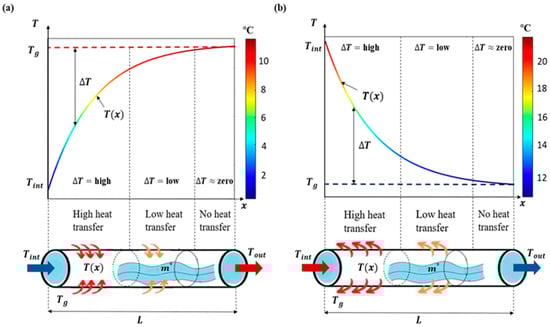
Figure 1.
Schematic diagram illustrating the heat transfer behavior of a vertical GHE in (a) heating mode and (b) cooling mode [7,8].
1.2. Advantages of Geothermal Heat Pump Systems
Geothermal heat pump systems (GHPSs) offer significant energy savings, using 25% to 50% less electricity than conventional heating and cooling systems. This is due to their high coefficient of performance (COP), which allows them to transfer three units of heat from the ground to the system using just one unit of electricity [3]. As a result, GHPSs can reduce heating costs by 30–60% and cooling costs by 20–50% compared to traditional heating and cooling systems [9,10]. It would be preferable for the GHPS’s power demands to be fulfilled through renewable energy sources rather than by drawing from electric utilities [11]. Furthermore, GHPSs are significantly more energy-efficient than conventional heating and cooling systems, particularly during the winter months. Unlike conventional heating systems that burn fuel to generate heat, GHPSs transfer existing heat from one place to another. Its heating efficiency is typically 30–70% higher than that of conventional heating systems and 20–50% more efficient than air conditioning systems [2,12,13,14]. Moreover, it is highly effective at regulating humidity, enhancing both comfort and overall energy efficiency [1]. GHPS boast a longer lifespan than most traditional heating and cooling systems, with their high-density polyethylene (HDPE) pipes lasting up to 50 years, while the heat pump unit typically lasts up to 25 years [3]. As a result, GHPSs are recognized as a clean, reliable, renewable, and sustainable energy source that requires minimal maintenance, contributing to its growing popularity compared to traditional heating and cooling systems. Additionally, GHPSs are considered one of the most promising stable renewable energy sources, as they are consistently available, unaffected by weather conditions, and depend entirely on the Earth’s relatively constant temperature. This enables them to maintain a consistent indoor climate year-round, unlike other renewable energy sources like solar and wind, which are subject to fluctuations based on weather conditions [12,15,16,17,18]. GHPSs operate with minimal noise, as their piping loops are buried underground, and the indoor unit generates sound levels like a typical refrigerator. In addition to its quiet operation, GHPSs offer significant environmental advantages, such as reducing greenhouse gas (GHG) emissions that contribute to global warming, and creating a quieter, less polluted environment. For example, compared to conventional heating and cooling systems powered by fossil fuels, GHPSs can reduce overall GHG emissions by up to 66% and carbon dioxide (CO2) emissions by as much as 50% [19]. After covering the initial installation costs, GHPSs are expected to recover the initial capital investment in as little as four to seven years, depending on the system configuration and the size of the underground loop [7,8,20,21]. Despite the high initial installation costs, GHPSs are expanding quickly due to their long-term cost savings. Thus, GHPSs are considered a rapidly growing technology globally, as demonstrated by the rising number of new installations each year [1,13]. For example, as of 2021, there were approximately 6.46 million ground-source heat pump (GSHP) units in operation across around 30 countries globally. The United States accounted for 1.7 million of these units, representing about 26.2% of the global installed base. In the United States, the majority of these systems—about 60%—were used for commercial applications, while the remaining 40% were for residential purposes, according to the International Energy Agency’s (IEA) 2020 Geothermal Report [22]. Furthermore, the installation rate in the United States is significant, with approximately 50,000 new GSHP systems being added each year, according to the International Ground Source Heat Pump Association [23]. This growing adoption reflects the increasing recognition of GSHPs as an efficient and sustainable solution for heating and cooling in both residential and commercial settings.
1.3. Disadvantages of Geothermal Heat Pump Systems
Despite their advantages, geothermal heat pump systems (GHPSs) have some drawbacks. One major disadvantage is the need for drilling to install the underground loop pipes, which increases installation complexity and cost compared to other renewable energy systems like solar panels or wind turbines [15]. Additionally, the initial investment for a GHPS is generally higher, with expenses typically 30% to 50% above those of traditional heating, ventilation, and air conditioning (HVAC) systems [24]. Thus, the cost of installing a residential geothermal heat pump system (GHPS) typically ranges from $10,000 to $30,000 [25]. This variation depends on factors such as the system’s configuration, the size of the underground loop, the amount of drilling needed, and the local soil thermal properties [1,4]. For instance, installing a GHPS in a standard 2000-square-foot home in the United States usually costs between $10,000 and $20,000 [26]. The vertical ground heat exchanger (VGHE) configuration requires extensive drilling, typically ranging from 30 to 130 m below the surface [27,28,29]. This setup can be quite expensive, especially if drilling through dense materials such as rock or stone. In contrast, the horizontal ground heat exchanger (HGHE) configuration requires shallower drilling—usually between 1.5 and 4 m deep—and is simpler and less costly to install [30]. As a result, it is a more popular choice for many households. However, the HGHE configuration requires a larger land area to bury the looping pipes. In both configurations, the cost of pipe materials, heat pumps, and installation services can be significant [1,4]. The installation process for a GHPS can take longer than that of other renewable energy systems, such as solar or wind, which may put pressure on both designers and installers. For example, installing a GHPS typically takes between 6 to 8 weeks, depending on factors such as system capacity, configuration, and soil thermal properties [29]. GHPSs have limited heating output because they relies on the Earth’s stable temperature, which may not meet building demands during cold months, especially in January and February [11]. In such cases, additional heating is needed, leading to costs. Its performance also varies by location—poor soil thermal properties can reduce its efficiency. These factors, along with high installation costs, limit the widespread use of GHPSs [7,8]. Advantages and disadvantages of geothermal heat pump systems (GHPSs) are summarized in Table 1.

Table 1.
Advantages and disadvantages of geothermal heat pump systems (GHPSs).
In this paper, we present a comprehensive analysis of geothermal heat pump systems (GHPSs), examining their benefits and limitations, key components, and various system types, with a primary focus on ground heat exchangers (GHEs). Furthermore, we provide an in-depth review of different closed-loop GHE configurations, discussing their influence on heat transfer efficiency, performance, and installation costs. The paper also emphasizes the importance of selecting the appropriate GHE configuration to optimize both system performance and economic feasibility. The remainder of the paper is organized as follows: Section 2 covers the geothermal heat pump system components, Section 3 discusses the types of geothermal heat pump systems, Section 4 presents a comparison of closed-loop ground heat exchanger configurations, and Section 5 provides a brief conclusion.
2. Geothermal Heat Pump System Components
Geothermal heat pump systems (GHPSs) generally comprise a heat pump, a distribution unit system, and a ground heat exchanger (GHE), as illustrated in Figure 2.
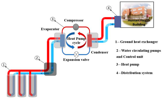
Figure 2.
Schematic diagram of a geothermal heat pump system [7].
2.1. Heat Pump
A heat pump is a thermodynamic device that transfers thermal energy from a lower-temperature source to a higher-temperature sink using mechanical work, typically via a vapor-compression refrigeration cycle. This process is significantly more energy-efficient than combustion-based systems, which rely on the generation of heat through fuel consumption. Instead of generating heat, heat pumps relocate it, reducing overall energy use and associated emissions. Due to their high performance and reversibility, heat pumps can be used for both space heating and cooling, making them highly suitable for building climate control applications [29,35,36,37]. The heat pump consists of three main components: the compressor, condenser, and evaporator, as shown in Figure 3. Geothermal heat pumps (GHPs) utilize the relatively stable temperature of the ground as a thermal reservoir, enabling superior efficiency compared to air-source heat pumps, which are affected by ambient temperature fluctuations [37,38]. Recent developments in vapor-compression cycle technologies, such as refrigerant injection and flash tank enhancement, continue to improve the energy efficiency and cold-weather performance of heat pumps, broadening their application potential in colder climates [39,40].
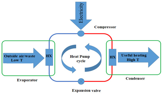
Figure 3.
Schematic of a heat pump system.
2.1.1. Working Principle
The working principle of a geothermal heat pump is grounded in the vapor-compression refrigeration cycle, which transfers heat between two reservoirs—typically the ground and the building interior—by circulating a refrigerant through a closed loop. This process adheres to the second law of thermodynamics, requiring mechanical energy input (usually via electricity) to move heat from a cooler region (e.g., the ground) to a warmer region (e.g., indoors). In heating mode, the heat pump extracts low-grade thermal energy from the ground and delivers it to the building. In cooling mode, the operation is reversed: the system removes excess heat from the indoor space and discharges it into the ground. This reversible cycle enables year-round operation [7,8,14].
The basic steps of the vapor-compression cycle are as follows:
- Evaporation: The refrigerant, at low pressure and temperature, absorbs heat from the ground loop and evaporates.
- Compression: The vapor is compressed to a high pressure and temperature.
- Condensation: The hot, high-pressure vapor releases heat to the building’s air or water distribution system and condenses into a liquid.
- Expansion: The refrigerant passes through an expansion valve, reducing its pressure and temperature before returning to the evaporator.
This continuous cycle enables bidirectional heat transfer, allowing the system to provide efficient climate control under varying seasonal demands. Because underground temperatures remain relatively constant year-round (typically 10–15 °C at moderate depths), geothermal systems can maintain higher coefficients of performance (COP) even in extreme outdoor conditions, outperforming air-source systems in cold climates [37,38,40].
2.1.2. Types of Heat Pumps in GHPSs
In geothermal heat pump systems (GHPSs), heat pumps are categorized based on how heat is exchanged between the ground loop and the building’s internal environment. The two main types are water-to-water and water-to-air heat pumps [41]. Each is selected according to the building’s HVAC system design, load distribution method, and regional climate.
Water-to-Water Heat Pumps
Water-to-water systems transfer heat between the geothermal loop and a water-based indoor distribution system. These are primarily used in radiant floor heating, hydronic baseboard radiators, and chilled water-cooling systems. They are especially favored in large commercial and institutional buildings where multiple zones require precise temperature control or where radiant heating is integrated into the building’s thermal envelope [42,43]. Water-to-water systems dominate in Europe and urban China, where hydronic infrastructure and centralized control strategies are widely adopted [44,45]. Their installation is common in schools, hospitals, and office buildings with high heating demands and a need for stable indoor environments [42,46,47,48].
Water-to-Air Heat Pumps
Water-to-air systems transfer heat from the geothermal loop to air, which is distributed indoors through ducts and air handlers. This type is most prevalent in North American residential buildings, where existing forced-air HVAC systems make integration cost-effective and straightforward [48,49]. These systems are ideal for single-family homes and light commercial applications are not designed for hydronic heating. Water-to-air systems are dominant in the United States and Canada, especially in regions where ducted HVAC systems are the standard for space conditioning. Their ease of retrofitting and compatibility with traditional HVAC infrastructure have made them the most common configuration in the residential geothermal market [14,48,49,50]. Example: In a typical residential installation, a water-to-air GHPSs extracts thermal energy from 10 °C groundwater and supplies heated air at approximately 35 °C through a forced-air duct system to maintain indoor comfort during winter [51]. The decision to implement either system depends on building architecture, retrofit potential, indoor climate control requirements, and cost considerations. In hybrid applications, both types may be used within the same building to optimize performance. A detailed comparison of water-to-water and water-to-air heat pump systems is presented in Table 2.
Table 2.
Detailed comparison of water-to-water and water-to-air heat pump systems.
2.1.3. Coefficient of Performance (COP)
The coefficient of performance (COP) is a key metric for assessing the energy efficiency of geothermal heat pump systems (GHPSs). COP is defined as the ratio of the heat energy delivered to the building to the work input () required to operate the system. Essentially, it measures the amount of heat produced per unit of energy consumed. The higher the COP, the more efficient the system, as it indicates that more heat is being transferred for each unit of electrical work used to drive the system. The COP is defined by the following equation:
where Q is the heat supplied, and > 0 is the work done by the system in one cycle. For cooling applications, COP is typically calculated as:
The COP for heating can be defined similarly:
where:
- is the heat absorbed from the low-temperature reservoir (the ground or groundwater),
- is the heat delivered to the building,
- is the work input (typically electricity used by the compressor).
Note that < 0, as it represents heat lost by the system [62].
In general, the coefficient of performance (COP) for geothermal heat pump systems (GHPSs) ranges between 3 and 6, meaning that for every unit of electrical energy input, the system delivers 3 to 6 units of heating or cooling. This high efficiency stems from the fact that geothermal systems transfer rather than generate heat, utilizing the ground’s stable temperature as a reliable thermal reservoir [1]. Numerous studies have shown that COP is highly influenced by system configuration, climate conditions, and technological integration. For instance, in Erzurum, Turkey—a region characterized by long, harsh winters—a seasonal average heating COP of 3.0 was observed, highlighting the efficiency reduction caused by the greater thermal gradient between the cold ambient air and the indoor setpoint temperature [63]. In contrast, systems operating in moderate climates have demonstrated significantly better performance. One study reported COPs of 3.7 for heating and 5.3 for cooling, attributed to the smaller temperature differential and more favorable ground conditions [64]. Additionally, in Bursa, Turkey, a horizontal ground-source system achieved overall system COPs between 2.46 and 2.58, whereas the heat pump unit alone performed at 4.03 to 4.18, emphasizing the impact of ground-loop design and installation quality on total system efficiency [65]. These regional examples underscore that while the underlying technology is inherently efficient, actual performance depends heavily on environmental context, ground thermal conductivity, and installation design. Further emphasizing this point, a comparative study by Salhein [1] evaluated GHPS installations at Oklahoma State University (USA), Universitat Politècnica de València (Spain), and Oakland University (USA). The system at Oklahoma State University exhibited the highest COP of 4.9, despite having the shallowest borehole depth of only 20 m, thanks to the area’s relatively high ground temperature of 22.1 °C. In contrast, the systems in Valencia and Michigan, with borehole depths of 50 m and 98 m, achieved COPs of 4.5 and 4.1, respectively consistent with their lower ground temperatures of 18.5 °C and 11.6 °C. As illustrated in Figure 4, these results highlight the significance of selecting GHPS sites with optimal thermal ground properties, which can lead to both improved performance and lower drilling costs [1]. Furthermore, Mitchell and Spitler [66] concluded that surface water heat pump systems can achieve high coefficients of performance (COP), with values of 4.2 for cooling and 4.0 for heating under optimal conditions. In summary, while GHPSs consistently outperform conventional HVAC systems in terms of energy efficiency, their effectiveness is not uniform across all environments. System design, local climate, ground conditions, and integration with renewable technologies must all be carefully considered to achieve high COP values and long-term operational benefits [30,42,67]. These findings emphasize that achieving high COP in GHPSs depends not only on the inherent technology but also on environmental context, operational mode, and system innovation.
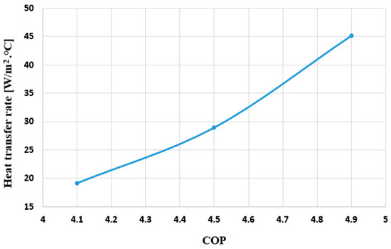
Figure 4.
Relationship of the geothermal heat transfer rate and coefficient of performance (COP) [1].
2.1.4. Advantages of Heat Pump Systems
Heat pump systems are highly efficient, with Coefficients of Performance (COP) typically ranging from 3.0 to 6.0, meaning they deliver three to six units of thermal energy for every unit of electricity consumed [52]. This high efficiency results from their ability to transfer heat using stable underground or air-source temperatures, reducing energy consumption by up to 75% compared to conventional systems [68,69]. Consequently, operational savings can reach 60% over the system’s lifespan, especially in heating-dominated climates [70]. Furthermore, heat pumps can reduce CO2 emissions by up to 50% compared to fossil-fuel-based systems, contributing to climate change mitigation [2,68,70]. Ground-source heat pumps maintain consistent performance due to the earth’s stable subsurface temperatures, making them ideal for regions with extreme seasonal conditions and ensuring reliable heating and cooling year-round [71].
2.2. Distribution System
The distribution system in a heat pump-based HVAC configuration functions as the intermediary that transfers thermal energy generated by the heat pump to the interior spaces of a building. It primarily operates through two delivery methods: hydronic (water-based) and forced-air (air-based) systems, chosen based on building design, climate, and application requirements.
Hydronic distribution systems utilize heated or cooled water circulated through a closed-loop piping network embedded in structural elements such as floors or walls. Radiant floor systems are a common application, delivering thermal comfort with minimal temperature stratification and high efficiency at low supply temperatures, typically between 30 °C and 50 °C [72]. Their effectiveness, particularly in heating-dominated climates, is from compatibility with low-exergy sources like heat pumps and enhanced heat transfer via radiation and conduction mechanisms [69].
Forced-air systems, by contrast, distribute conditioned air via ductwork and are widely used in residential and light commercial buildings. These systems are advantageous where existing duct infrastructure is present or where cooling demand is significant, offering relatively fast thermal response and integrated ventilation capabilities [73]. Air is conditioned through a coil connected to the heat pump and circulated using fans, with supply temperatures typically ranging from 30 °C to 45 °C in heating mode [74,75]. This ducted air distribution system is the most common in the USA [1,76,77,78].
2.3. Ground Heat Exchanger
The ground heat exchanger (GHE) is a critical component of a geothermal heat pump system (GHPS), enabling thermal energy exchange between the system and the earth by leveraging the earth’s relatively stable subsurface temperature. It typically consists of a network of looped pipes made from high-density polyethylene (HDPE), a material favored in geothermal applications for its durability, thermal stability, and corrosion resistance [7,29,30,79]. A heat-transfer fluid—usually water or a water-antifreeze mixture—circulates through these pipes in a closed-loop configuration to absorb or dissipate heat, depending on seasonal heating or cooling demands. GHE systems are generally categorized by their pipe layout, which can be vertical, horizontal, or slinky (coiled), depending on factors such as land availability, soil composition, and installation costs. In vertical systems, boreholes are drilled deep into the ground—often between 50 to 150 m—where U-shaped pipes are inserted; these are ideal for areas with limited surface space. Horizontal systems involve laying the pipes in shallow trenches—typically 1 to 2 m deep—making them more suitable for locations with ample land area. Slinky (coiled) systems use overlapping loops of pipe laid in horizontal trenches, offering a compact alternative to traditional horizontal layouts and improving heat exchange in limited space [29,80,81]. The performance of the GHE is significantly influenced by thermal conductivity of the surrounding soil or rock, moisture content, pipe depth, and loop design, all of which directly impact heat exchange efficiency [29,52]. Accurate sizing and proper system design are essential to prevent long-term thermal imbalances in the ground, which can degrade system performance over time. Consequently, modern GHE design practices incorporate advanced simulation tools and detailed site-specific geological assessments to optimize efficiency and minimize long-term energy losses [29]. When evaluating the thermal performance of a GHE, underground thermal properties—particularly thermal conductivity and heat capacity—emerge as the most influential factors, as demonstrated by numerous sensitivity analyses in the literature [82,83]. Studies consistently show that the relative impact of other design variables diminishes as ground thermal conductivity increases. In other words, systems installed in high-conductivity soils or rocks generally perform more consistently despite design variations, while those in low-conductivity ground require more precise design to maintain efficiency. Identifying and understanding local geological properties can significantly enhance GHE performance [8,29]. This highlights the importance of conducting accurate site-specific geotechnical investigations in the early stages of system planning. It also reinforces the value of thermal response testing (TRT) and numerical modeling for characterizing the subsurface and predicting long-term system behavior.
2.3.1. Environmental and Operational Performance Factors of GHEs
Several studies have investigated the key environmental and operational factors that significantly influence the performance and efficiency of ground heat exchangers (GHEs). These factors include soil moisture content, pipe material choices, system configurations, and operational conditions, all of which are crucial for optimizing the design and performance of GHE systems Numerical simulation of horizontal ground heat exchangers (HGHEs) showed that factors such as coating soil height and moisture content could enhance the specific heat transfer rate by up to 50% [84]. Additionally, the use of backfill materials with high moisture retention capacity was recommended, as increased water content helped mitigate thermal saturation in the surrounding soil [85]. Several experimental studies reported an increase in average heat transfer rates in moist soil by 22.7–24.1% during cooling and 15.6–22.8% during heating, depending on moisture levels between 5% and 20% [86]. Furthermore, Cuny et al. [87] conducted both experimental and numerical analyses that demonstrated the impact of rainfall-induced changes in soil moisture on the performance of ground heat exchangers (GHEs). In their study, a laboratory-scale experimental setup was used to simulate rainfall events with varying intensity and duration, examining their effect on soil moisture content. The resulting vertical moisture profiles were then applied in numerical modeling of Earth-to-Air Heat Exchangers (EAHEs)—systems that precondition ventilation air by transferring heat with the ground. The simulations revealed that rainfall events led to short-term enhancements in energy performance, with a 4% increase in the first 24 h and an additional 2% over the next 24 h [87]. In addition, Kaushal [88] reviewed various algorithms and analytical models used for the analysis and sizing of EAHE systems, highlighting the importance of design parameters such as pipe material, diameter, length, and thermal interference. Singh et al. [89] extended this understanding by examining the effects of surface treatment on EAHE thermal performance and presenting insights into practical installations and innovative system configurations. Complementing these findings, Agrawal et al. [90] investigated the influence of geographical and climatic factors, operational parameters, and the role of latent heat exchange on overall EAHE performance.
Many studies investigating ground heat exchangers (GHEs) have been published, including review papers addressing various aspects of shallow geothermal energy utilization. The application, investigation, and sizing of GHE systems vary significantly across countries, largely influenced by local climatic conditions, development levels, and regulatory frameworks. Although similar design parameters, materials, and working fluids are commonly employed, their impact on performance differs across GHE configurations. Younes et al. [91] compiled a comprehensive range of studies examining how various GHE parameters influence the performance and efficiency of ground-source heat pump (GSHP) systems. While their review encompassed both horizontal and vertical configurations, particular emphasis was placed on vertical systems. Yuanlong et al. [92] extended this work by reviewing analytical and numerical models used to evaluate the thermal performance of diverse vertical GHE configurations. In addition, Hossein et al. [93] explored recent advancements in GHE system design, focusing on material innovations, configuration strategies, and performance optimization techniques. Yuanlong et al. [94] presented various analytical, numerical, and economic models for evaluating the performance of horizontal GHE systems, concluding that the inclusion of advanced economic models—rarely applied in current practice—would enhance assessments of financial metrics like inflation and the time value of money. Abubakar et al. [95] investigated the key parameters influencing the thermal performance of energy piles, in addition to outlining essential design procedures and analyzing their techno-mechanical behavior. Faizal et al. [96] provided a focused review on heat transfer enhancement strategies and geometric optimization for energy piles. Jevgeni et al. [97] provided a comprehensive analysis of energy pile configurations, as well as the analytical and numerical modeling techniques and sizing methodologies used in their design. Notably, they emphasized that energy piles are frequently misidentified as vertical boreholes, despite significant differences in geometry and thermal behavior. Among all GHE configurations, vertical borehole heat exchangers remain the most thoroughly studied in the literature. Among all GHE configurations, vertical borehole heat exchangers remain the most extensively studied. Amin and Michel [98] compared a range of commercial sizing tools for vertical BHEs, finding that most tools estimate similar borehole lengths, despite using models of varying complexity.
Moreover, investigations into the operation of ground heat exchangers (GHEs) under transient conditions, conducted by several authors, revealed the benefits of cyclic operation and the use of metal pipe materials with higher thermal conductivity in enhancing system performance [99,100]. Surface conditions also play a significant role in affecting GHE performance, as variations in factors such as soil moisture, temperature, and type of ground material can lead to different efficiency outcomes. Rouag et al. [101] concluded that the performance of open-type systems, such as Earth-to-Air Heat Exchangers (EAHEs), is particularly influenced by ambient temperature fluctuations. In contrast, horizontal GHE systems experience a smaller impact from annual surface temperature variations, especially when the effects of installation depth dampen these fluctuations. This finding highlights the importance of design choices such as pipe layout, as these factors have a more pronounced effect on heat exchange efficiency compared to seasonal temperature changes.
In multi-pipe GHE configurations, the layout of the main distribution pipe and its connection to parallel pipe sections also plays a vital role in system performance. Studies have shown that U-type or L-type configurations are preferable over Z-type layouts due to lower pressure drops (up to 36% reduction), improved flow uniformity (up to 80% higher), and a modest but meaningful increase in heat transfer rate (up to 5.8%) [102,103]. Furthermore, in multilayered configurations, a staggered pipe arrangement significantly enhances heat transfer compared to a strictly parallel layout. When the horizontal displacement between upper and lower pipe layers is equal to their vertical separation (e.g., offset), the heat transfer rate can improve by as much as 47% over the parallel configuration [104]. These findings emphasize the impact of hydraulic and geometric design decisions on both operational efficiency and long-term system reliability. Two widely used configurations for vertical ground heat exchangers (GHEs) are the coaxial borehole heat exchangers (BHE) and the U-tube BHE. These two designs differ primarily in the arrangement of pipes within the borehole, each offering distinct advantages in terms of heat transfer efficiency, installation requirements, and cost [85]. The coaxial BHE features a pipe-within-a-pipe design, where the inner pipe carries the fluid while the outer pipe serves as the return flow pathway. This design is known for its improved heat transfer characteristics, especially in applications requiring higher thermal performance. In contrast, the U-tube BHE consists of a single pipe bent in a U-shape, providing a simpler and often more cost-effective solution, though typically with lower thermal efficiency compared to coaxial systems.
Gordon et al. [105] improved the semi-analytical modeling of coaxial BHEs by investigating variations in pipe material, specifically comparing an insulated inner pipe with a steel outer pipe against the standard high-density polyethylene (HDPE) as the baseline case. They concluded that using a steel outer pipe significantly reduces the required depth of the BHE. Similarly, Kwanggeun, et al. [106] conducted experimental studies on the heat exchange performance of various coaxial-type GHEs. They constructed four different 50-m deep coaxial BHEs in a testbed, testing different grouting materials, pipe diameters, and materials. Their findings showed that thermal performance improves with larger pipe diameters and higher thermal conductivity of both the pipe and grouting material. However, the improvements were not linear, indicating the need to optimize these factors based on construction costs. These results demonstrate the importance of considering both material properties and design choices in maximizing the performance of coaxial GHE systems.
Kerme and Fung [107] conducted performance analysis of U-tube BHEs using unsteady heat transfer simulations. To reduce the impact of climate and environmental factors on GHE performance and to enhance heat extraction, drilling deeper boreholes (DBHE) has been suggested as a viable solution, as demonstrated by Deng et al. [108]. Numerical simulations are often employed to explore the heat transfer process in DBHE systems. However, these simulations face limitations due to the geothermal gradient, rendering conventional numerical and analytical models unsuitable for shallower BHEs. In response to these challenges, Fang et al. [109] developed an efficient and accurate numerical algorithm for analyzing DBHEs, offering a significant advancement in computational efficiency and precision. Additionally, numerical models for DBHE heat transfer have been further developed by Song et al. [110] (unsteady state) and Liu et al. [111] (logarithmic discretization in the radial direction). Renaud et al. [112] introduced a CFD model for DBHEs located near magma intrusions. As these simulations progress, the need for analytical models has become increasingly essential, as they enable faster and more practical design and calculation of DBHEs. As mentioned, the geothermal gradient is significant, so models for BHEs do not apply to DBHEs. Aiqiang et al. [113] and Yongqaing et al. [114] presented analytical heat transfer models for coaxial DBHEs. These models simplified heat transfer, so Luo et al. [115] improved the analytical modeling of heat transfer in DBHEs with their model based on a segmented finite cylinder-source model. Another important consideration in modeling DBHEs was presented by Hu et al. [116] analyzed the effects of temperature-dependent properties on the prediction of output capacity of DBHEs under operational conditions. The properties included in the numerical simulation were specific heat, thermal conductivity of water and reservoir rocks, and the density and dynamic viscosity of the fluid. They concluded that output capacity can be overpredicted by up to 9%.
Gao et al. [117] provided an overview of various ground heat exchanger (GHE) system layouts and their integration with different heating and cooling technologies in the context of zero-energy buildings. Similarly, Soni et al. [118] analyzed hybrid systems that employ multiple renewable energy sources for heating and cooling applications. Aresti et al. [119] summarized a comparative analysis of various geometrical aspects of GHEs, geothermal investigations, and materials. Furthermore, Salhein et al. [29] conducted a comprehensive review of factors influencing GHE performance, including soil thermal properties, backfill material properties, borehole depth, spacing, U-tube pipe properties, and working fluid type and velocity. They discussed their impact on heat transfer efficiency and proposed optimal solutions for enhancing GHE performance.
2.3.2. Advanced Materials in Ground Heat Exchanger Design
Thermally Enhanced Pipe Materials
In geothermal heat pump systems, the pipe functions as a key thermal interface between the working fluid (such as pure water or an antifreeze solution) and the surrounding soil or backfill material. Because heat transfer performance is strongly affected by the pipe material, it is essential for the pipe to possess high thermal conductivity to efficiently facilitate heat exchange in both directions. Additionally, the pipe must be mechanically durable, flexible, resistant to wear and leaks, long-lasting, easy to install, and cost-effective [1,7,8,29,120]. Currently, high-density polyethylene (HDPE) is the most used pipe material in GHE systems due to its low cost, fusion-weldability, corrosion resistance, and long service life, often exceeding 50 years [121]. The typical cost of HDPE piping ranges from USD 1 to USD 30 per linear foot, depending on diameter, wall thickness, and regional pricing factors [122]. Despite its widespread use, HDPE’s thermal conductivity—generally between 0.35 W/m·K and 0.49 W/m·K—is considerably lower than that of the circulating fluid and surrounding earth [123,124,125]. This results in increased borehole thermal resistance and reduced heat transfer efficiency, which ultimately limits overall GHE system performance [7]. Therefore, enhancing the thermal conductivity of HDPE is a critical step toward improving energy efficiency and reducing the required borehole depth in geothermal applications.
In recent years, numerous advancements in HDPE (high-density polyethylene) pipe materials have been introduced to improve their thermal conductivity for ground heat exchanger (GHE) applications. For example, Bassiouny et al. [126] embedded 2 mm and 3 mm aluminum wires into HDPE pipes, resulting in thermal conductivity improvements of 25% and 150%, respectively. Additionally, Jasmin et al. [127] incorporated thermally conductive additives into the HDPE resin during the extrusion process, achieving a 75% increase in thermal conductivity—from 0.4 to 0.7 W/m·K—and a 24% reduction in borehole thermal resistance. Moreover, Bouhacina et al. [128] enhanced the pipe’s internal geometry by adding longitudinal fins, leading to a 7% increase in heat extraction compared to traditional HDPE pipes. In a similar approach, Hamid et al. [129] developed a graphite-infused HDPE composite, which reduced the required borehole length by 12.76% while maintaining system performance. Another study by Yiyou et al. [130] achieved a thermal conductivity of 2.38 W/m·K by combining 40% boron nitride (BN) sheets with 7 wt.% carbon nanotubes (CNTs) in an ultra-high-molecular-weight polyethylene (UHMWPE) matrix. This level of performance is comparable to that of metallic materials while still preserving the durability, flexibility, and corrosion resistance of polymer pipes. Collectively, these studies highlight the growing potential of thermally enhanced polymeric composites to optimize GHE design, reduce installation depth, and improve long-term energy efficiency.
Building upon these foundational developments, researchers have also explored the use of hybrid filler systems in polymer matrices to establish more efficient heat conduction networks [131,132]. Junjin et al. [133] demonstrated that combining carbon nanotubes with expanded graphite led to a synergistic double-filler network that markedly improved thermal conductivity. Similarly, Shengqiang et al. [134] reported that incorporating both T-ZnO and hexagonal boron nitride (h-BN) into HDPE yielded superior thermal performance. When the BN:T-ZnO mass ratio was maintained at 2:1, the composite exhibited a thermal conductivity of 1.27 W m−1 K−1 while maintaining excellent electrical insulation. Furthermore, Mingjie et al. [135] utilized a combination of h-BN and multi-walled carbon nanotubes (MWCNTs) in HDPE, finding that ternary composites outperformed binary ones, with thermal conductivity increasing by up to 262% compared to the base polymer. Junjin et al. [136] also explored fabrication techniques and found that HDPE/BN/CNT composites prepared via hot rolling exhibited significantly higher thermal conductivity than those processed by hot pressing. In another study, Zhi-Guo et al. [137] applied BN and AlN to ultrahigh-molecular-weight polyethylene (UHMWPE) particles to form a hybrid network structure using high-pressure molding. With a BN:AlN ratio of 6:1 and a total filler load of 50 wt%, the composite achieved a thermal conductivity of 7.1 W m−1 K−1. Moreover, incorporating both nano- and micro-scale fillers has been shown to further improve the thermal and mechanical performance of polymer composites [138,139]. For instance, Lihua et al. [140] introduced nano sized SiC and micro-scale boron nitride microspheres (BNMS) into epoxy composites. The resulting nanocomposites exhibited a 158% enhancement in thermal conductivity, as the nanoscale fillers acted as bridges between the microscale structures, facilitating better heat transfer.
Expanding on this research direction, several recent studies have demonstrated remarkable improvements in thermal conductivity and mechanical properties through advanced hybrid systems. Hamid et al. [129] conducted a comparative study on thermally conductive fillers in HDPE composites for ground heat exchangers and identified low-temperature expandable graphite as an effective additive. Their simulation showed that incorporating just 10 wt% of this filler (thermal conductivity ≈ 1.4 W/m·K) could reduce borehole length by 10%, achieving over 68% of the maximum potential reduction. They further concluded that composites with thermal conductivity ≥2 W/m·K could eliminate the need for metal tubing in some applications. Yuyuan et al. [141] developed an expanded graphite/graphene composite (EGC) by incorporating 3.5 wt% graphene oxide (GO) into expanded graphite (EG) via vacuum-assisted self-assembly followed by compaction and graphitization. This design achieved excellent through-plane (18.6 W m−1 K−1) and in-plane (129.9 W m−1 K−1) thermal conductivities. GO acted as a phonon transmission “bridge” both within and between EG particles, significantly boosting thermal performance. Additionally, the EGC showed improved mechanical strength, reaching 7.9 MPa at 15% strain, which surpassed pure EG. Wei et al. [142] further enhanced through-plane thermal conductivity by integrating 20 wt% carbon fibers into EG composites, achieving 10.8 W m−1 K−1. To further optimize the structure, carbon nanotubes were introduced between EG interlayers via chemical vapor deposition, aligning the graphite layers and raising thermal conductivity to 24.3 W m−1 K−1 [143]. Shahil et al. [144] also demonstrated a 2300% improvement in cross-plane thermal conductivity by incorporating a mixture of graphene and multilayer graphene using liquid-phase exfoliation. At just 2 vol% filler loading, thermal conductivity in commercial grease increased from ~5.8 to 14 W m−1 K−1, primarily due to graphene’s high aspect ratio and low interfacial resistance. In a related development, Zhenliang et al. [145] fabricated HDPE/BN composites via melt blending and achieved a 282.37% increase in thermal conductivity to 1.648 W m−1 K−1. This improvement was attributed to uniform BN dispersion, increased crystallinity, and the formation of efficient phonon conduction paths, which were further supported by simulation results. Junjin et al. [136] demonstrated that combining hybrid fillers—boron nitride (BN) and carbon nanotubes (CNTs)—with orientation via hot-rolling significantly enhanced the thermal conductivity of HDPE composites, achieving up to a 600% increase. The study emphasized the critical role of filler alignment and network formation in maximizing thermal transport efficiency. Darabut et al. [146] treated expandable graphite at temperatures between 400–800 °C to produce thermally expanded graphite (TEG), achieving a sixfold increase in electrical conductivity. Optimal results—including high conductivity, large expansion volume, and minimal structural defects—were observed at 600 °C. Kallaev et al. [147] showed that although thermally expanded graphite is phonon-dominated in thermal transport, its thermal conductivity is markedly lower than traditional graphite or carbon-based nanofillers, limiting its standalone effectiveness in high-conductivity applications. Furthermore, Krupa et al. [148] demonstrated that the thermal and electrical conductivity of HDPE/graphite composites are significantly influenced by the graphite particle size and surface area. In addition, their findings showed that different graphite types led to varying percolation thresholds within the semicrystalline HDPE matrix. Consequently, both the thermal and mechanical properties were dependent not only on graphite loading but also on its physical characteristics. Therefore, careful selection of graphite fillers can play a crucial role in optimizing the multifunctional performance of HDPE-based composites.
Moreover, Xueming et al. [149] developed HDPE/BN/CSC composites using boron nitride and coconut shell charcoal as hybrid fillers. Owing to their synergistic effect, the HDPE/25BN/3CSC composite exhibited a 980.89% increase in in-plane thermal conductivity, a 138% rise in normal conductivity, and an 18.91% improvement in tensile strength compared to pure HDPE, along with enhanced thermal stability and electrical insulation. Owais et al. [150] developed epoxy nanocomposites with hybrid fillers—graphene nanoplatelets (GNPs), boron nitride (BN), and short carbon fibers (SCF)—achieving high thermal conductivity (~0.8 W/m·K) and excellent electrical insulation at low filler content. This approach enhanced heat dissipation, thermal stability, and maintained electrical resistivity suitable for electronics applications. Similarly, Chao et al. [151] developed thermoplastic urethane (TPU) composites enhanced with hybrid fillers of expanded graphite (EG) and multi-layer graphene (MLG), achieving a thermal conductivity of 8.52 W m−1 K−1 at 20 wt% EG and 10 wt% MLG—representing a 3450% improvement over pure TPU. They attributed this enhancement to a strong thermal synergy between the fillers, with a TCE efficiency of 115% per 1 wt% filler. The thermal conduction mechanism was supported by morphological and interfacial resistance analyses, and finite element simulation verified their potential in LED thermal management applications. Patrik et al. [152] developed HDPE/expanded graphite (EG) composites for use in multi-effect distillation (MED) desalination systems, achieving a 372% improvement in thermal conductivity at 50 wt% EG loading. They also enhanced the surface wettability through RF and corona plasma treatments, increasing surface energy from 28.5 mJ/m2 to 55.5 and 54.5 mJ/m2, respectively, with only minor declines after two months. Processing behavior was found to depend on EG content—extrusion was optimal below 30 wt%, while injection molding was favored above that threshold. In addition, plasma-treated composites demonstrated an overall heat transfer coefficient that reached 98% of stainless steel and showed superior resistance to crystallization fouling in both CaSO4 solution and artificial seawater.
In recent years, natural plant-based fibers have emerged as promising sustainable alternatives to traditional glass and carbon fibers in composite fabrication [153]. These bio-based fibers are particularly appealing due to their low density, biodegradability, cost-effectiveness, and minimal environmental impact. When incorporated into polymer matrices—especially in combination with hybrid fillers—they have demonstrated the potential to significantly improve mechanical strength, thermal conductivity, and long-term structural durability [154,155]. Kirupairaja et al. [156] demonstrated that incorporating coconut fibers into cement–soil blocks significantly improved residual strength, ductility, and energy absorption. Additionally, coconut fiber reinforcement enhanced resistance to alkali and acid erosion, and improved durability under freeze–thaw and dry–wet cycles. Kumaran et al. [157] explored rosewood chip–reinforced jute fiber epoxy composites and found that the hybrid system enhanced flexural and compressive strength, stiffness, and impact energy absorption. These improvements were attributed to better stress transfer and energy dissipation within the composite structure. Arifuzzaman et al. [158] fabricated polypropylene and low-density polyethylene (LDPE) composites using a combination of coconut shell fiber (CSC) and banana fiber as hybrid fillers. They reported substantial gains in Young’s modulus, tensile strength, impact resistance, and flexural strength. Similarly, Suiyi et al. [159] developed UHMWPE composites infused with bamboo charcoal via extrusion and hot pressing. The resulting composites exhibited improved tensile performance, enhanced thermal stability, and increased electrical conductivity, confirming the multifunctional benefits of bio-based hybrid reinforcements.
Thermally Conductive Grouting Materials
Grouting materials are essential in ground heat exchanger (GHE) systems because they fill the annular space between the heat exchange pipes and the borehole wall, ensuring mechanical stability, preventing collapse, and facilitating efficient thermal exchange with the surrounding ground. This backfill material can consist of native soil or engineered admixtures designed to improve contact between the pipe and the earth [160]. The grout’s thermal conductivity is a critical factor influencing the overall heat exchange efficiency. To minimize borehole thermal resistance and avoid air pockets—which create thermal discontinuities or contact resistance, it is essential to fully grout the borehole with materials that maintain continuous thermal contact between the pipe and surrounding formation [7,8]. Traditional bentonite- or cement-based grouts have relatively low thermal conductivities—typically between 0.4 and 0.8 W/m·K—which limits system performance and often necessitates deeper or additional boreholes to meet heating and cooling loads [1]. Therefore, using thermally enhanced grouts with higher thermal conductivity can significantly improve GHE performance.
To overcome the limitations of traditional low-conductivity grouts, recent studies have explored incorporating thermally conductive additives such as silica sand, graphite, aluminum oxide (Al2O3), and carbon-based nanomaterials into grout formulations [161]. These modifications aim to significantly enhance heat transfer efficiency while preserving critical grout properties like mechanical strength, pumpability, and durability. For instance, de Paly et al. [161] showed that Al2O3-enhanced geopolymer grouts achieved thermal conductivities near 1.9 W/m·K and offered improved chemical stability compared to traditional cement-based grouts, making them promise for sustainable geothermal applications. In addition, extensive experimental and simulation research confirms the crucial role of backfill thermal conductivity in improving ground heat exchanger (GHE) performance. For example, Smith and Perry [162] found that increasing backfill conductivity boosts heat transfer rates between the circulating fluid and surrounding soil, enhancing overall system heat capacity. Dehkordi and Schincariol [163] reported that raising grout conductivity from 1 to 3 W/m·K led to over 10% improvement in heat extraction by reducing borehole thermal gradients. Alberti et al. [164] demonstrated that increasing grout conductivity from 0.7 to 2.3 W/m·K lowered borehole thermal resistance dramatically from 0.135 to 0.054 m·K/W. Furthermore, Saeidi et al. [165] showed that enhancing thermal conductivity of both ground and backfill from 0.5 to 2 W/m·K increased heat transfer rates by 40% and 48%, respectively. Steven [166] highlighted that using thermally enhanced backfill materials can reduce borehole length by up to 10%, lowering drilling and installation costs. Moreover, Aminhossein [167] demonstrated that highly conductive backfill materials elevate borehole wall temperatures and decrease thermal resistance, resulting in improved heat exchange efficiency and system stability.
In addition to field validations, recent research has provided deeper insight into the mechanisms by which thermally enhanced backfill materials improve ground heat exchanger (GHE) performance. Marita and Aristodimos [168] demonstrated that high-conductivity grout materials can form stronger thermal bridges between the pipe wall and surrounding ground, significantly improving heat transfer. Song et al. [169] confirmed that as the thermal conductivity of the backfill increases, the overall system heat transfer rate increases proportionally—while lower conductivity materials degrade performance. Zang et al. [170] investigated the influence of backfill material conductivity on GHE pipe length using four configurations. Their experiments revealed that increasing grout thermal conductivity allowed for a notable reduction in total pipe length, with the greatest effect observed in double U-tube configurations with 32 mm outer diameters, followed by 25 mm double U-tubes, and then single U-tubes. This finding supports system optimization by minimizing material use without sacrificing thermal output. Chang and Kim [171] further analyzed the breakdown of borehole thermal resistance, concluding that the grout’s contribution accounts for over 65% of the total borehole thermal resistance. This underscores the critical role of backfill selection in reducing thermal bottlenecks. Therefore, to optimize GHE performance, the thermal conductivity of the grout should be at least equal to, or ideally higher than, that of the surrounding soil, maximizing bidirectional heat exchange [7,8].
In selecting backfill materials, environmental and geological conditions must also be considered. For instance, Lee et al. [172] recommended using cementitious grouts in dry soil conditions due to their lower water retention and higher resistance to desiccation and shrinkage, which can otherwise lead to cracking and reduced thermal contact. In contrast, quartz sand offers notable thermal advantages—Pahud and Matthey [173] found that replacing bentonite with quartz sand in the grout mixture reduced borehole thermal resistance by up to 30%, directly enhancing heat transfer efficiency. This reduction in thermal resistance minimizes the temperature gradient across the borehole wall, improving the rate of energy exchange with the ground. As illustrated conceptually in Figure 5, there is an inverse relationship between borehole thermal resistance and heat transfer rate: as resistance increases, the capacity of the GHE system to transfer heat diminishes. Thus, selecting grout materials with high thermal conductivity is not merely a matter of performance optimization—it is crucial for ensuring system longevity, reducing operational costs, and achieving sustainability goals. These findings collectively highlight the importance of advanced grouting formulations and site-specific material selection in the design and operation of efficient GHE systems.
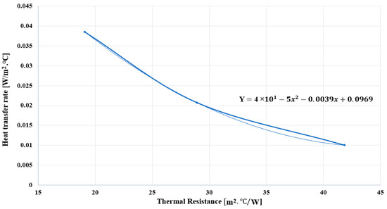
Figure 5.
Inverse relationship between thermal resistance and heat transfer rate in geothermal systems [1].
3. Types of Geothermal Heat Pump Systems
Geothermal heat pump systems (GHPSs) are broadly categorized into two main types based on the configuration of their ground heat exchanger (GHE): open-loop systems and closed-loop systems, as illustrated in Figure 6. Closed-loop systems are further classified into three configurations: vertical, horizontal, and pond/lake systems, depending on how and where the piping network is installed.
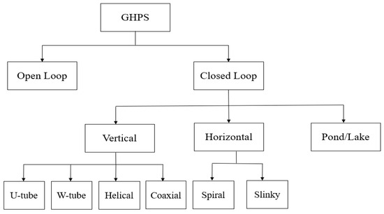
Figure 6.
Types of geothermal heat pump systems (GHPSs) [1].
3.1. Open-Loop Geothermal Heat Pump Systems
An open-loop geothermal heat pump system is a geothermal heating and cooling system that directly utilizes water from a natural source, such as groundwater or a surface body of water, for heating and cooling purposes. Figure 7 shows the open-loop geothermal heat pump system. Furthermore, the open-loop geothermal heat pump system is commonly referred to as a “pump-and-dump” system. Water is drawn from the source, passed through the geothermal unit where its thermal energy is exchanged, causing changes in temperature, and then returned to the original source. Unlike closed-loop systems, which circulate sealed fluid in a closed circuit, open-loop systems rely on continuous water withdrawal and discharge. While these systems offer superior heat exchange efficiency and lower installation costs, they are vulnerable to issues related to water quality, such as contamination or sediment buildup, which can damage the system and increase maintenance costs. Thus, their use is limited to locations with a reliable and clean water supply, making them less versatile than closed-loop systems, which do not rely on external water sources [1,2,3,174,175,176,177,178,179]. Open-loop systems are frequently used in regions with abundant groundwater availability, such as parts of the United States, Canada, and Northern and Central Europe, where hydrogeological conditions are favorable [176]. Maya et al. [180] introduced an efficient upscaling methodology for incorporating highly transient real-world operation data from open-loop geothermal systems into hydrogeological models. Their approach allows for urban-scale simulations while reducing data complexity by over 90%, enabling accurate representation of system exploitation patterns and supporting sustainable resource management. Dato et al. [181] investigated the impact of aquifer heterogeneity on thermal feedback in open-loop geothermal systems. The study revealed that while conductivity heterogeneity significantly influences thermal breakthrough time, it has minimal impact on the recirculating ratio. The authors concluded that advection-only models in homogeneous media are adequate for predicting the long-term behavior of shallow open-loop systems. Previati et al. [182] assessed the potential of a shallow alluvial aquifer in Milan to support low-enthalpy geothermal systems in response to the region’s high thermal energy demand. Using analytical methods, they evaluated both closed-loop (ground-coupled heat pump) and open-loop (groundwater heat pump) configurations, considering local regulations, hydrogeological characteristics, and environmental considerations. Their results were compared with municipal building heat demand to identify the most efficient and sustainable geothermal system design.
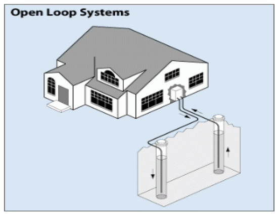
Figure 7.
Open-loop geothermal heat pump system [3].
3.2. Closed-Loop Geothermal Heat Pump Systems
A closed-loop geothermal system is a widely adopted ground-source heat pump (GSHP) configuration in which a heat transfer fluid—typically a mixture of water and antifreeze—is circulated through a sealed network of underground pipes, usually made of high-density polyethylene (HDPE). These systems operate in a closed circuit, meaning the fluid does not come into contact with the surrounding environment and is continuously recycled through the loop. Heat is exchanged between the circulating fluid and the ground: in winter, the fluid absorbs heat from the earth and delivers it to the heat pump, while in summer, it carries excess heat from the building and dissipates it into the cooler ground. This process enables efficient thermal energy transfer with minimal energy input and no depletion of natural groundwater sources. Closed-loop systems are known for their reliability, low environmental impact, and long service life—often exceeding 25 years for indoor components and 50 years for underground piping. They are highly adaptable and can be installed in a variety of configurations—horizontal, vertical, or pond/lake-based—depending on factors such as available land area, subsurface conditions, and project-specific design requirements. These configurations offer flexibility in both urban and rural settings, contributing to the growing popularity of closed-loop systems worldwide. The characteristics and applications of each configuration will be discussed in the following sections [1,3,174,175,176,177,183].
3.2.1. Vertical Closed-Loop Geothermal Systems
The vertical ground heat exchanger (GHE), also known as a borehole heat exchanger (BHE), is one of the most widely implemented configurations in geothermal heat pump systems (GHPSs). A schematic of vertical closed-loop GHE is presented in Figure 8. This configuration is particularly suitable in areas where land availability is limited or where the ground is rocky. Vertical GHEs generally provide more stable thermal performance than horizontal systems, as they are installed deep enough—typically between 30 and 120 m—where ground temperatures remain relatively constant throughout the year [7,8,28,29,184,185,186]. Borehole diameters usually range from 0.1 to 0.2 m [29,187,188,189,190], and the spacing between boreholes is commonly between 5 to 7 m to minimize thermal interference [29,191,192,193,194,195]. The system utilizes high-density polyethylene (HDPE) loop pipes inserted vertically into the ground, and the boreholes are backfilled with thermally conductive grout to ensure efficient heat transfer and prevent air gaps, which could reduce the system’s heat transfer efficiency [7,8,162]. The use of high thermal conductivity backfills materials, such as bentonite or cement-based grouts with added silica sand, significantly enhances the heat exchange process and increases the long-term reliability of the system. Depending on design and performance needs, various pipe configurations can be employed, including single U-tube, double U-tube, triple U-tube, multi-tube, helical, W-tube, or coaxial loops [196,197,198,199,200,201,202]. These configurations can be arranged in series or parallel circuits, with parallel systems generally offering higher efficiency despite requiring more piping [203,204].
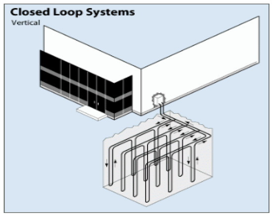
Figure 8.
Vertical closed-loop geothermal heat pump system [3].
Although vertical GHEs require a higher upfront cost due to the need for drilling, they are particularly advantageous in urban or space-constrained locations [22,82,205]. Approximately 60–70% of vertical GHE systems are installed in residential homes and commercial buildings, with 30–40% used in larger-scale applications like hospitals and industrial facilities. In residential settings, they are valued for their energy efficiency and space-saving benefits, particularly in urban areas. The commercial sector adopts vertical GHEs for their effectiveness in meeting high heating and cooling demands in office buildings, schools, and retail spaces [206,207]. For larger applications, vertical GHEs are ideal for hospitals, industrial facilities, and government buildings, where consistent energy use is crucial. Hospitals benefit from their stable performance, which is essential for maintaining controlled environments, while industrial facilities use them for processing cooling and space conditioning. As environmental awareness increases, vertical GHEs are increasingly incentivized due to their sustainability benefits, making them a strategic choice in both the private and public sectors. The system design—specifically the number, depth, and diameter of the boreholes—depends on the thermal characteristics of the subsurface and the heating and cooling demands of the building [7,8,208,209]. Salhein et al. [29] conducted a comprehensive study analyzing the factors such as soil thermal properties, grout materials, borehole geometry, U-tube characteristics, and fluid dynamics that influence the overall thermal performance, proposing optimization strategies to improve system efficiency. In practice, the thermal response test (TRT) is widely used to determine the effective thermal conductivity of the ground and the thermal resistance of the borehole. These values are critical for accurate system sizing and simulation. Interestingly, single U-tube systems are more prevalent in North America, whereas double U-tube configurations are more commonly used in Europe [210]. Overall, vertical GHEs are ideal for long-term, high-efficiency geothermal applications, particularly in locations where land is expensive or limited and where geological conditions support deep drilling. Vertical GHE systems are becoming increasingly popular in both residential and commercial sectors due to their durability, efficiency, and sustainability, despite their higher initial installation costs.
3.2.2. Horizontal Closed-Loop Geothermal Systems
Horizontal ground heat exchangers (GHEs) are among the most widely adopted configurations in closed-loop geothermal heat pump systems, particularly in regions where sufficient land is available and excavation is economically feasible. Their relatively shallow installation depth and simpler construction process contribute to lower initial costs, making them a practical and cost-effective solution for residential and light commercial applications. When geological conditions—such as rocky terrain or unstable subsoil—render vertical drilling impractical or cost-prohibitive, horizontal systems present a practical alternative. In such cases, where sufficient surface area is available, horizontal configurations are often favored for their ability to provide a balanced trade-off between thermal performance and reduced installation costs [82,211,212]. As illustrated in Figure 9, the horizontal GHE involves burying polyethylene heat exchange pipes in long, shallow trenches, typically spaced at least 1.5 m apart and placed at depths ranging from 2 to 6 m, depending on local climate and soil conditions. The required pipe length generally falls between 35 and 60 m per kilowatt (kW) of heating or cooling capacity, depending on the thermal conductivity of the soil and the system load [30,66,213]. This shallow burial depth makes horizontal systems more susceptible to seasonal temperature fluctuations, unlike vertical configurations that benefit from more stable ground temperatures.
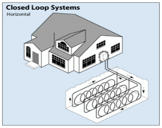
Figure 9.
Horizontal closed-loop geothermal heat pump system [3].
Pipe layout configurations in horizontal systems vary and can include straight (linear), spiral, or slinky loops, each offering specific advantages depending on site constraints and thermal performance goals [3,99,186]. The slinky (coiled) configuration is particularly space-efficient, allowing a longer pipe length to fit within a shorter trench by overlapping the coils. This layout reduces the surface area required, which is beneficial in smaller plots. However, slinky loops can have slightly lower thermal efficiency compared to conventional linear horizontal loops due to thermal interference between adjacent coils [214,215]. Parallel pipe connections are generally preferred over series configurations in horizontal systems, as they reduce hydraulic resistance and pumping power requirements, thereby improving energy efficiency. On the other hand, while spiral and vertical arrangements tend to provide higher heat transfer rates, they often come with greater installation complexity or cost, making the horizontal system a practical compromise between performance and affordability [211,216]. In residential settings, horizontal GHEs are appreciated for their lower installation cost and ease of maintenance. In educational or small public facilities, they offer an affordable solution to meeting year-round energy demands.
The thermal performance of horizontal GHEs is strongly influenced by soil thermal conductivity, moisture content, backfill material, and trench depth. Soils with higher moisture content typically provide better heat transfer properties, enhancing system efficiency. Additionally, because excavation is shallower, horizontal systems are often easier to inspect, modify, or repair, making them suitable for retrofits and low-rise buildings, particularly in moderate to warm climates where deep ground temperatures are not essential for system performance. In summary, while horizontal closed-loop systems may require more land and are less thermally stable than vertical systems, they remain a cost-effective and practical choice for buildings with moderate energy demands, especially when budget constraints or site accessibility limit the feasibility of deeper drilling.
3.2.3. Pond/Lake Closed-Loop Geothermal Systems
The pond or lake loop configuration, often referred to as a lake loop system, is a type of closed-loop geothermal heat pump system that utilizes a nearby body of water—such as a pond, lake, or slow-moving river—as the medium for heat exchange. Due to water’s higher thermal conductivity compared to soil, this setup offers improved heat transfer efficiency, making it one of the most energy-efficient configurations [217]. In this setup, a series of polyethylene loop pipes—typically arranged in a slinky or coiled pattern—are connected to the building’s heat pump and submerged directly into the water body. These loops are usually anchored to racks or weighted frames and installed at a depth of approximately 2.5 to 3 m (8 to 10 feet) below the water surface, where temperature conditions remain relatively stable year-round [217,218,219]. A schematic diagram of a typical pond/lake heat exchanger is shown in Figure 10. In heating mode, a water-antifreeze mixture circulates through submerged piping in a pond or lake, where it absorbs thermal energy from the surrounding water. This heat is then transferred to a heat pump located within the building, which uses a vapor-compression cycle to elevate the temperature and distribute it throughout the building via a forced-air or hydronic system. However, in cooling mode, the process is reversed: the heat pump extracts heat from the indoor air and transfers it to the circulating fluid, which then releases the heat into the pond, ensuring efficient indoor cooling even during peak summer temperatures [220]. The system utilizes the stable temperature of natural water bodies to provide sustainable year-round climate control. One of the major advantages of the pond/lake configuration is its cost-effectiveness. Because it does not require trenching or deep drilling, installation is generally quicker and less expensive than vertical or horizontal systems, especially when a water body is located nearby. The pipes can be prefabricated, mounted on skids, and towed into place, significantly simplifying deployment and reducing labor time [66,217]. However, the system’s feasibility is highly dependent on-site conditions, particularly the availability and characteristics of the water source. The body of water should meet specific criteria—such as adequate depth, sufficient surface area, and consistent year-round thermal stability—to ensure efficient heat exchange and minimize risks like freezing in winter or overheating in summer. Environmental regulations and water quality must also be considered, as aquatic ecosystems can be sensitive to human intervention and thermal changes [66]. These systems are commonly used in rural residences, recreational facilities, and small commercial buildings near suitable water sources. As interest in sustainable energy solutions increases, pond/lake systems are becoming a preferred choice wherever geographic and environmental conditions are favorable.
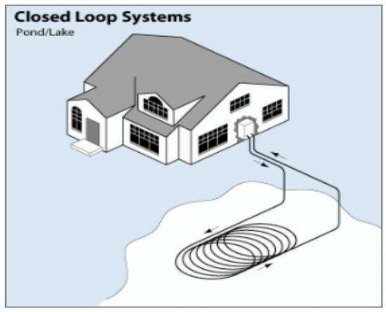
Figure 10.
Pond/Lake closed-loop geothermal heat pump system [3].
3.3. Comparison of Closed-Loop and Open-Loop Geothermal Heat Pump Systems
Closed-loop geothermal heat pump (GHP) systems operate by circulating a heat exchange fluid through a sealed, continuous loop of high-density polyethylene (HDPE) piping buried underground. This closed circuit ensures long-term reliability, thermal stability, and low maintenance requirements, with system lifespans typically ranging from 50 to 100 years. This makes closed-loop systems particularly suitable for a wide variety of settings, including urban and environmentally sensitive environments, where access to a consistent and clean water supply may be limited or unreliable. These systems are widely recognized for their versatility, energy efficiency, and environmentally responsible operation, as they do not consume or discharge groundwater, thereby avoiding issues related to water resource depletion, contamination, or permitting complications. Depending on land availability and site conditions, closed-loop configurations can be installed vertically (in deep boreholes), horizontally (in trenches), or in compact spiral (slinky) layouts. This flexibility allows for broad application across residential, commercial, and institutional projects. However, closed-loop systems typically involve higher initial capital costs, largely due to the need for excavation, trenching, or deep drilling operations. Additionally, their spatial requirements and installation complexity may pose constraints in densely built or physically restricted areas. Despite these drawbacks, closed-loop systems are favored for their long-term operational savings and predictable performance.
In contrast, open-loop geothermal systems extract groundwater directly from an external source—such as a well, pond, or lake—for heat exchange. After the thermal energy transfer, the water is discharged, typically into a separate well or surface water body. These systems generally offer lower upfront costs and simpler installation procedures, as they eliminate the need for extensive underground piping. They also exhibit high thermal transfer efficiency due to direct contact with the water source. However, open-loop systems are dependent on a reliable, sustainable, and clean water supply, which may limit their feasibility in regions with variable hydrological conditions. Moreover, they are more susceptible to issues such as sediment accumulation, mineral scaling, corrosion, biological fouling, and fluctuations in water quality, all of which can significantly impact performance, increase maintenance frequency, and reduce system lifespan. To mitigate these challenges, filtration systems, chemical treatments, and routine inspections are often necessary. Additionally, open-loop systems may have a greater environmental footprint due to the withdrawal and reinjection of groundwater, which raises concerns about aquifer depletion, thermal pollution, regulatory compliance, and potential disruption of local ecosystems. These factors necessitate ongoing monitoring and strict adherence to local environmental regulations. Ultimately, closed-loop systems offer greater durability, long-term sustainability, and minimal operational oversight, making them ideal for projects prioritizing environmental protection and system longevity. On the other hand, open-loop systems—although potentially more cost-effective and efficient in water-abundant regions—require rigorous water management and more frequent maintenance to ensure consistent and environmentally responsible operation over time [1,174,175,176,177,178,183,221,222]. Table 3 summarizes the comparison between closed-loop and open-loop geothermal heat pump systems.
Table 3.
Comparison of closed-loop and open-loop geothermal heat pump systems.
4. Discussion: Comparison of Closed-Loop Ground Heat Exchanger Configurations
Some closed-loop configurations are more efficient in heat transfer and have lower installation costs than others. For instance, Cui et al. [223] highlighted that vertical ground heat exchangers (GHEs) generally provide superior energy performance compared to horizontal systems. Florides et al. [224] compared the efficiency of vertical and horizontal GHEs through modeling. Their simulations showed that as the initial ground temperature increased, the mean fluid temperature in the vertical GHE rose linearly. Although vertical GHEs generally maintained lower fluid temperatures due to higher ground temperatures at greater depths, they suggested that optimizing the design—such as increasing tube spacing—could reduce fluid temperature and improve efficiency. Sáez Blázquez et al. [225] concluded that the spiral ground heat exchanger configuration requires a shallower drilling depth than the U-tube configuration, leading to significant reductions in initial capital costs. They also found that helical-shaped pipes provide superior thermal efficiency compared to single and double U-tube heat exchangers, enhancing performance and reducing the required drilling depth for the same length. Furthermore, their study revealed that double-tube heat exchangers do not offer a significant improvement in thermal exchange over single U-tube systems, with the primary benefit being redundancy in case of failure. Additionally, the use of spacers in U-tube heat exchangers increased efficiency by approximately 30% compared to configurations where the inlet and outlet pipes were in direct contact. Kerme et al. [226] conducted a numerical analysis of single U-tube and double U-tube BHE configurations, revealing that the double U-tube configuration with a larger borehole size provided the best thermal performance, while the single U-tube with a smaller borehole size demonstrated the lowest performance. Heyie et al. [196] found that double U-tube configurations demonstrated better thermal performance compared to single U-tube systems. Despite this, the single U-tube remains the most widely used due to its ease of installation, lower cost, and compact space requirements [203,211]. Miyara et al. [227] evaluated the performance of ground heat exchangers (GHEs) in cooling mode. The results showed that the double-tube GHE had the highest heat exchange rate (49.6 W/m), followed by the multi-tube (34.8 W/m) and U-tube (30.4 W/m) GHEs. Furthermore, Yavuzturk and Chiasson [228] used a thermal resistance model to compare the thermal performance of various ground heat exchangers, including single U-tube, double U-tube, concentric tube, and standing column well (without groundwater bleed). The results showed that the single U-tube required the longest bore length, while the double U-tube, concentric tube, and standing column well reduced the bore length by 22%, 33%, and 36%, respectively. Kerme et al. [226] agreed with Miyara et al. [227], Yavuzturk and Chiasson [228], and Geo et al. [229] that the double U-tube BHE configuration provided better heat transfer performance than the single U-tube ground heat exchanger.
Furthermore, Zarrella et al. [230] compared the performance of helical-shaped pipes and double U-tube ground heat exchangers installed at shallow depths, considering the impact of ground-surface interaction and ambient conditions on thermal behavior. The results indicated that the helical heat exchanger demonstrated better thermal performance than the double U-tube. A comparison of the performance of eight new types of helical ground heat exchangers (GHEs) with a single U-tube GHE was conducted by Javadi et al. [231]. The results showed that the triple helix GHE outperformed all other designs, followed by the double helix and W-tube GHEs, while the single U-tube GHE demonstrated the lowest thermal performance and pressure drop among all the models. Furthermore, Dinh et al. [232] compared eight innovative helical ground heat exchangers with a single U-tube design. The triple helix offered the best thermal performance, whereas the U-tube had the lowest pressure drop but the lowest overall efficiency. Seung-Rae Lee et al. [233] evaluated the thermal performance of four ground heat exchanger (GHE) configurations—U-tube, W-tube, double U-tube (2U), and coil-type—installed in partially saturated silt-clay landfill ground at Incheon International Airport, South Korea. Thermal response and performance tests were conducted to assess the ground’s thermal conductivity and heat exchange rates. The measured thermal conductivities were 2.13 W/m·K for the U-tube, 2.15 W/m·K for the W-tube, and 2.17 W/m·K for the 2U-tube. Corresponding heat exchange rates were 35.71 W/m (U-tube), 40.76 W/m (W-tube), 39.03 W/m (2U-tube), and 76.8 W/m (coil-type). The W-tube and 2U-tube configurations achieved approximately 10–15% higher heat exchange rates than the U-tube, attributed to their larger heat exchange surface areas. Furthermore, Seung-Rae Lee et al. [233] conducted a heat performance test under continuous cooling operation for 100 h on borehole heat exchangers. They found that partial operation over 5 days using W-shaped and coil-type GHEs resulted in average heat exchange rates of 54.16 W/m and 103 W/m, respectively—30–40% higher than those under continuous operation. This improvement is attributed to reduced heat saturation in the ground, which otherwise lowers heat transfer efficiency during prolonged operation. In summary, heat exchange rates varied significantly with the shape of the geothermal heat exchanger, and operation conditions influenced efficiency by 30–100% due to heat buildup in the ground. Periodic operation proved more effective than continuous operation [233].
Moreover, Gao et al. [229] investigated the heat transfer performance of various ground heat exchanger configurations, including single U-tube, double U-tube, triple U-tube, and W-shaped tubes. Their analysis showed that the W-shaped tube configuration provided superior performance compared to the other configurations. Zhang et al. [234] reviewed heat transfer models for ground heat exchangers (GHEs) with buried coils, including line, cylindrical, and ring-coil sources. They noted that while borehole GHEs are the most common, pile foundation GHEs are gaining interest due to their improved thermal performance and lower installation costs. Xia et al. [197] evaluated several factors affecting heat transfer, including heat exchanger type, water velocity, inlet temperature, and operation mode. They found that the W-shaped heat exchanger achieved 1.2 to 1.4 times higher heat exchange rates than the single U-shaped type; the optimal water velocity ranged from 0.6 to 0.9 m/s; each 1 °C increase in inlet temperature led to a 15% increase in the heat exchange rate. Furthermore, Chen et al. [202] developed 3D models of double-U and enhanced coaxial BHEs with spiral ring fins, considering groundwater seepage and variations in heat transfer across different soil and rock layers. Simulations under different conditions demonstrated that the enhanced coaxial BHE outperformed the double-U BHE, with its heat transfer per linear meter being 1.46 times higher in winter and 1.45 times higher in summer, respectively. Furthermore, Harris et al. [235] used a custom numerical model in OpenFOAM v2012 to compare the performance of coaxial and U-tube borehole heat exchangers. The analysis showed that both designs performed similarly in the long term due to high soil resistance, with the most significant differences observed during the early transient phase. Coaxial heat exchangers with polyethylene piping exhibited minimal differences in outlet temperature after 72 h. However, using a steel coaxial outer tube improved performance by 22% compared to the U-tube design. Moreover, Harris et al. [236] studied the impact of intermittent operation on coaxial and U-tube borehole heat exchangers. They found that U-tubes outperformed coaxial designs for durations shorter than the transit time, while coaxial BHEs performed up to 12.9% better for longer durations. Rajeh, et al. [237] evaluated the performance of coaxial and multi-external-chamber coaxial ground heat exchangers (GHEs). The results showed that coaxial GHEs provided the best thermal performance, with 127.54% higher maximum heat transfer and 17.67% higher average heat transfer rates than double U-tube GHEs, respectively. Replacing double U-tube GHEs with coaxial designs reduced the number of GHEs by 13.3%, water pump energy consumption by 33.91%, and total system energy use by 17.21%, respectively. A coaxial ground heat exchanger can reduce the borehole depth by 23%, as noted by Raymond et al. [200]. Furthermore, Sliwa et al. [238] conducted numerical simulations on three GHE configurations—single U-tube, double U-tube, and coaxial—to assess the impact of grout material on resistivity and effective thermal conductivity. Their results revealed that the coaxial GHE provided the best performance.
Bezyan et al. [239] investigated the thermal performance of vertical spiral-shaped pipe configurations in geothermal pile foundation heat exchangers, comparing them with 1-U-shaped and 1-W-shaped configurations in cooling mode. Their results showed that spiral-shaped pile-foundations with a serial connection achieved the highest heat transfer rate and efficiency compared to the other configurations. Mehrizi et al. [204] simulated geothermal coil heat exchangers in a ground-coupled heat pump (GCHP) system for cooling mode, comparing three vertical pile-foundation configurations: 1-U-shaped, 1-W-shaped, and W-shaped-all round (6-U pipes arranged around the pile). The numerical results demonstrated that the W-shaped-all round configuration achieved the highest heat transfer efficiency. Moreover, pile-foundations with serial connections showed better performance and efficiency compared to those with parallel connections.
Yoon et al. [198] examined the thermal performance of precast high-strength concrete (PHC) energy piles with W-type and coil-type ground heat exchangers (GHEs) using experimental tests and numerical simulations. Their results indicated that coil-type GHEs were 10–15% more efficient than W-type GHEs, but the W-type GHEs were 200–250% more cost-effective in terms of installation. While coil-type GHEs required fewer piles, making them suitable for larger projects, the W-type GHEs provided a more economical solution with comparable thermal performance. Additionally, the W-tube BHE configuration is approximately 14% more efficient than the U-tube ground heat exchanger [240]. Yoon et al. [241] indicated that W-tube GHE configurations exhibit a 10–15% higher average heat exchange rate compared to U-tube GHE configurations. Moreover, Asgari et al. [242] used a 3D numerical model to assess the thermal performance of various horizontal GHE pipe arrangements (linear, spiral, and slinky). The linear GHE with a quadruple-layer arrangement demonstrated the highest heat exchange rate, 34% greater than the single-layer configuration. The staggered double-layer arrangement was optimal in slinky and spiral GHEs improving heat exchange by 22% and 7% respectively. Kurevija et al. [243] compared vertical and inclined coaxial borehole heat exchangers (BHEs) in a consistent geological setting. The results showed that the vertical 2-U-loop BHE demonstrated superior heat extraction (54.5 W/m compared to 43.5 W/m) and lower thermal resistance than the coaxial system. Furthermore, Lee et al. [244] performed an in-situ thermal response test in Wonju, South Korea, evaluating six vertical ground heat exchangers with different grouting materials such as cement and bentonite and pipe configurations including U-loop and 3-pipe designs. The study found that the 3-pipe design reduced thermal interference between the inlet and outlet resulting in superior thermal performance compared to the conventional U-loop configuration. Moreover, Yoon et al. [215] evaluated the heat exchange rates of horizontal slinky, spiral-coil, and U-type ground heat exchangers in a steel box filled with dry sand using 30-h thermal response tests. The U-type GHE showed the highest heat exchange rate per pipe length, achieving 2 to 2.5 times the thermal efficiency of both the horizontal slinky and spiral-coil GHEs. Additionally, a longer pitch interval (pitch/diameter = 1) resulted in 100–150% higher heat exchange rates compared to a shorter pitch interval (pitch/diameter = 0.2) for both spiral-coil and horizontal slinky designs. Chong et al. [245] pointed out that a horizontal slinky-loop heat exchanger with smaller loop pitches results in better thermal performance and lower installation costs, although it leads to higher material costs. Thus, loop pitch has a greater impact on thermal performance than loop diameter. Thus, as the coil diameter in the slinky heat exchanger increases, heat extraction per meter of soil rises, while increasing the central coil interval distance reduces heat extraction per meter of soil. Furthermore, Fujii et al. [213] investigated the optimal design of slinky-coil horizontal ground heat exchangers using the FEFLOW finite-element simulation tool. Their study demonstrated that slinky-coil systems offer a space-efficient and cost-effective alternative to traditional configurations, though a reliable and standardized design method is still lacking.
Luo et al. [246] conducted an evaluation study of the thermal efficiency of four ground heat exchanger types in energy piles—double-U, triple-U, double-W, and spiral—through thermal performance tests under intermittent heating and cooling conditions. The results showed that the triple-U type provided the highest thermal efficiency, followed by the spiral and double-W types, which exhibited similar performance. The double-U type had the lowest thermal efficiency. Additionally, the spiral type with a 32 mm diameter demonstrated a 32% higher heat transfer rate compared to the 25 mm version. A cost-benefit analysis revealed that the triple-U type offered the best economic performance, followed by the double-U, spiral, and double-W types. However, thermal efficiency was found to be a more important factor than pipe material costs in practical applications. Law et al. [247] conducted a study modeling GSHP systems in four buildings—a hospital, restaurant, residence, and school—using different borehole configurations (2 × 2, 4 × 4, 2 × 8). The results indicated that the 6-m separation distance recommended by ASHRAE may not have been sufficient to prevent thermal interactions between boreholes. The (2 × 8) configuration, offering a larger perimeter for heat dissipation, outperformed the (4 × 4) configuration. Song et al. [203] developed a 3D unsteady-state numerical model to simulate fluid flow and thermal processes in a downhole heat exchanger (DHE) system, evaluating spiral, parallel, and serial tube configurations. The results showed that the serial connection outperformed the parallel connection in terms of outlet temperature and thermal power. Among the three configurations, the spiral tube DHE demonstrated the highest heat extraction performance, offering valuable insights for optimizing DHE design. Furthermore, Florides et al. [211] compared the heat performance of single and double U-tube GHE configurations in both series and parallel connections. The results showed that the double U-tube configuration, whether connected in series or parallel, outperformed the single U-tube BHE configuration. Interestingly, the most used geometries are multi-tube, single U-tube, double U-tube, and triple U-tube configurations. Other designs include coaxial setups, such as pipe-in-pipe geometry or multiple pipes surrounding a central pipe.
Kim et al. [214] evaluated the performance of horizontal ground heat exchangers (GHEs) through both experimental tests and numerical simulations. Thermal response tests (TRTs) were conducted using slinky- and spiral-coil GHEs installed in a steel box filled with Joomunjin sand. The results demonstrated that spiral-coil GHEs provided superior heat exchange performance compared to slinky-type GHEs. Numerical simulations confirmed the experimental findings, identifying GHE type and soil thermal conductivity as the primary factors influencing heat transfer, while pipe diameter had no significant impact on performance. The U-type ground heat exchanger is the most economical while delivering equivalent thermal performance compared to the horizontal slinky and spiral-coil types, as noted by Yoon et al. [215]. Moreover, Acuña [199] conducted field tests with U-pipe and coaxial BHEs, including a thermosiphon, in groundwater-filled boreholes, employing the new Distributed Thermal Response Test (DTRT) method to assess local BHE performance. Their results showed that coaxial BHEs, particularly pipe-in-pipe design, exhibited lower thermal resistances and reduced temperature differences, allowing for the use of water instead of antifreeze. Additionally, nitrogen bubble-induced forced convention reduced thermal resistance in U-pipes by 30%, enhancing heat transfer efficiency. Furthermore, Raymond et al. [200] performed analytical design calculations that demonstrated the coaxial pipe configuration was more efficient than the single U-pipe, reducing borehole length by up to 23% for a cooling-dominated building load profile. This reduction was attributed to a lower borehole thermal resistance and the increased thermal mass provided by the water in the coaxial exchanger. The improved thermal resistance was achieved by using an outer pipe made of thermally enhanced high-density polyethylene, with a thermal conductivity of 0.7 W m−1 K−1. Zarrella et al. [248] compared helical and triple U-tube configurations in foundation piles using a numerical simulation tool that modeled heat transfer through thermal resistances and capacitances. The results showed that the helical configuration provided better thermal performance than the triple U-tube design. Moreover, Congedo et al. [249] investigated the thermal performance of three heat exchanger types—linear (straight), helical, and slinky. They modeled a 50 mm pipe diameter buried at depths of 1.5 m, 2.0 m, and 2.5 m, analyzing the effects of installation depth, soil thermal conductivity, heat transfer fluid velocity, and loop pitch on the helical and slinky-loop configurations. Among these, the helical model, with a loop diameter of 0.4 m and pitch values of 0.1 m, 0.2 m, and 0.3 m, demonstrated the best thermal performance. Thus, the helical configuration is more attractive than other GHE configurations, as it relies on shorter GHEs [201].
Moreover, the helical configuration provides a significant cost advantage, with installation and material costs for the spiral heat exchanger being 30% lower than those of the double U-tube heat exchanger configuration [250]. Habibi et al. [84] developed a 3-D numerical model to evaluate the installation costs of horizontal ground heat exchangers (GHEs) in four configurations: linear, spiral, horizontal slinky, and vertical slinky. The results showed that the spiral and linear configurations offered the lowest installation costs in single and parallel arrangements, respectively. Additionally, the study found that applying secondary soil with improved thermal properties near the GHE pipes reduced installation costs when the secondary soil’s thermal conductivity and heat capacity were higher than those of the background soil. Evaluation of the installation costs of different ground heat exchanger configurations, including triple U-tube, double U-tube, double W-tube, and spiral tube, was carried out by Luo et al. [246]. The results indicated that the triple U-tube configuration offered the best economic performance, followed by the double U-tube, spiral tube, and double W-tube configurations. Furthermore, the W-type GHE in energy piles is 200–250% cheaper than coil-type GHEs, while providing similar thermal performance. However, fewer piles are required for coil-type GHEs, offering advantages in construction time [198]. Therefore, the coil-type GHE is a suitable option when there are limitations on the number of piles, depending on the building’s scale. The summary of ground heat exchanger (GHE) configurations, including thermal performance, cost efficiency, and key insights, is presented in Table 4.
Table 4.
Summary of ground heat exchanger (GHE) configurations: thermal performance, cost efficiency, and key insights.
5. Conclusions
In this paper, we provide a comprehensive analysis of geothermal heat pump systems (GHPSs), addressing their benefits, limitations, key components, and configuration types, with a primary focus on closed-loop ground heat exchangers (GHEs). Our review highlights the critical role GHE design plays in determining the thermal performance, operational efficiency, and overall cost of GHPS installations.
A detailed evaluation of various vertical closed-loop GHE configurations revealed that helical and spiral designs offer enhanced thermal efficiency with reduced drilling depth and installation costs, making them favorable for shallow or pile-integrated systems. Coaxial GHEs, particularly those constructed with thermally enhanced or steel tubes, exhibit low thermal resistance and shorter borehole requirements, contributing to significant performance and economic benefits. Triple U-tube and W-type configurations provide high heat exchange rates, striking a balance between system efficiency and installation cost, while multi-U configurations offer redundancy and consistent performance, albeit with greater complexity and expense.
Our analysis also confirmed that operation mode has a major influence on system efficiency, with intermittent operation outperforming continuous operation by up to 100% due to reduced ground saturation. Factors such as optimal borehole spacing, backfill material selection, and the use of thermally enhanced grouts further contribute to system optimization, reducing lifecycle costs while improving thermal output.
Despite the availability of advanced configurations, the single U-tube remains the most installed GHE, followed by the double U-tube, due to their cost-effectiveness, design simplicity, and wide applicability. Table 5 illustrates the estimated installation and economic analysis shares of different GHE types, showing that while innovative designs like coaxial, spiral, and triple U-tube systems are less frequently deployed, they offer specific advantages under particular site and load conditions.
Table 5.
Estimated percentage of total installations and economic analysis for various GHE configurations.
Overall, the optimal GHE configuration for a GHPS depends on project-specific parameters such as geological conditions, thermal loads, spatial limitations, and budgetary constraints. While advanced configurations like helical, coaxial, and multi-U systems offer superior performance and long-term benefits, simpler designs such as the single U-tube remain highly practical for standard and cost-sensitive applications. The insights presented in this study aim to support informed decision-making in the selection and optimization of GHE systems, promoting the development of high-efficiency, cost-effective, and sustainable geothermal energy solutions. Future research should explore the integration of advanced materials—such as nanofluids, phase change materials, and thermally enhanced grout—to improve the thermal performance and durability of GHE systems. Additionally, the application of numerical modeling and machine learning for site-specific optimization could lead to more efficient, cost-effective, and adaptive geothermal system designs, and enhance overall system performance.
Author Contributions
Conceptualization, K.S. and S.A.S.; methodology, K.S. and A.M.A.; software, K.S.; validation, C.J.K., M.H. and E.Y.A.; formal analysis, A.M.A. and K.S.; investigation, S.A.S. and M.H.; resources, M.H. and E.Y.A.; data curation, K.S.; writing—original draft preparation, K.S.; writing—review and editing, K.S., S.A.S. and C.J.K.; visualization, K.S. and A.M.A.; supervision, M.Z.; project administration, K.S.; funding acquisition, M.Z. All authors have read and agreed to the published version of the manuscript.
Funding
This research received no external funding.
Data Availability Statement
No new data were created or analyzed in this study.
Conflicts of Interest
The authors declare no conflicts of interest.
Abbreviations
| BHE | borehole heat exchanger |
| BTR | borehole thermal resistance |
| CNT | carbon nanotube |
| COP | coefficient of performance |
| DBHE | deep borehole heat exchanger |
| GCHP | ground-coupled heat pump |
| GHE | ground heat exchanger |
| GHP | geothermal heat pump |
| GHPS | geothermal heat pump system |
| GSHP | ground source heat pump |
| HDPE | high-density polyethylene |
| IEA | International Energy Agency |
References
- Salhein, K.A.A. Modeling and Control of Heat Transfer in a Single Vertical Ground Heat Exchanger for a Geothermal Heat Pump System. Ph.D. Thesis, Oakland University, Rochester, MI, USA, 2023. [Google Scholar]
- Omer, A.M. Ground-source heat pumps systems and applications. Renew. Sustain. Energy Rev. 2008, 12, 344–371. [Google Scholar] [CrossRef]
- Saver, E. Geothermal Heat Pumps. Available online: https://www.energy.gov/energysaver/geothermal-heat-pumps (accessed on 12 November 2024).
- Salhein, K.; Ashraf, J.; Zohdy, M. Output temperature predictions of the geothermal heat pump system using an improved grey prediction model. Energies 2021, 14, 5075. [Google Scholar] [CrossRef]
- Zhao, J.; Wang, H.; Li, X.; Dai, C. Experimental investigation and theoretical model of heat transfer of saturated soil around coaxial ground coupled heat exchanger. Appl. Therm. Eng. 2008, 28, 116–125. [Google Scholar] [CrossRef]
- Kavanaugh, S.P. Field Tests for Ground Thermal Properties—Methods and Impact on Ground-Source Heat Pump Design. Master’s Thesis, University of Alabama, Tuscaloosa, AL, USA, 2000. [Google Scholar]
- Salhein, K.; Kobus, C.; Zohdy, M. Control of heat transfer in a vertical ground heat exchanger for a geothermal heat pump system. Energies 2022, 15, 5300. [Google Scholar] [CrossRef]
- Salhein, K.; Kobus, C.; Zohdy, M. Heat Transfer Control Mechanism in a Vertical Ground Heat Exchanger: A Novel Approach. In Fundamental Research and Application of Physical Science; B P International: London, UK, 2023; Volume 5, pp. 59–90. [Google Scholar]
- United States General Accounting Office. Geothermal Energy: Outlook Limited for Some Uses But Promising for Geothermal Heat Pumps. 1994. Available online: https://www.gao.gov/products/rced-94-84 (accessed on 12 November 2024).
- Philippacopoulos, A.J.; Berndt, M.L. Influence of Debonding in Ground Heat Exchangers Used With Geothermal Heat Pumps. Geothermics 2001, 30, 527–545. [Google Scholar] [CrossRef]
- Salhein, K.; Kobus, C.; Zohdy, M. Forecasting installation capacity for the top 10 countries utilizing geothermal energy by 2030. Thermo 2022, 2, 334–351. [Google Scholar] [CrossRef]
- Salhein, K.; Ashraf, J.; Zohdy, M. Enhanced Grey Prediction Model (IGM (1, 1)) for Accurate Geothermal Heat Pump Stations Output Temperature Forecasting. Geogr. Earth Sci. Environ. Res. Highlights 2025, 7, 150–167. [Google Scholar]
- Salhein, K.; Kobus, C.; Zohdy, M. Forecasting Geothermal Installation Capacity Worldwide to 2030: Application of an Improved Grey Prediction Model to the Top 10 User Countries. Geogr. Earth Sci. Environ. Res. Highlights 2025, 8, 64–85. [Google Scholar]
- Assad, M.E.H.; AlMallahi, M.N.; Ramadan, A.; Awad, M.A.; Rejeb, O.; AlShabi, M. Geothermal heat pumps: Principles and applications. In Proceedings of the 2022 Advances in Science and Engineering Technology International Conferences (ASET), Dubai, United Arab Emirates, 21–24 February 2022; pp. 1–8. [Google Scholar]
- Alhawsawi, E.Y.; Salhein, K.; Zohdy, M.A. A Comprehensive Review of Existing and Pending University Campus Microgrids. Energies 2024, 17, 2425. [Google Scholar] [CrossRef]
- Hawsawi, M.; Habbi, H.M.D.; Alhawsawi, E.; Yahya, M.; Zohdy, M.A. Conventional and switched capacitor boost converters for solar PV integration: Dynamic MPPT enhancement and performance evaluation. Designs 2023, 7, 114. [Google Scholar] [CrossRef]
- Alhawsawi, E.Y. A Unified Framework for Multi-Level Control and Multi-Objective Optimization of Hybrid Campus Microgrids: Integrating Adaptive MPC, Modified Firefly Algorithm, and Homer Simulations. Ph.D. Thesis, Oakland University, Rochester, MI, USA, 2024. [Google Scholar]
- Alhawsawi, E.Y.; Habbi, H.M.D.; Hawsawi, M.; Zohdy, M.A. Optimal design and operation of hybrid renewable energy systems for Oakland university. Energies 2023, 16, 5830. [Google Scholar] [CrossRef]
- Zogg, M. History of Heat Pumps-Swiss Contributions and International Milestones; Swiss Federal Office of Energy: Bern, Switzerland, 2008. [Google Scholar]
- Heat, G. Geothermal Energy Outlook Limited for Some Uses but Promising For; United States General Accounting Office: Washington, DC, USA, 1994. [Google Scholar]
- Miles, H. Heat Pump vs. Geothermal Systems: Which is Best? 2021. Available online: https://homeinspectioninsider.com/heat-pump-vs-geothermal-systems-which-is-best/ (accessed on 7 November 2024).
- Office of Energy Efficiency & Renewable Energy. IEA 2020 U.S. Geothermal Report; U.S. Department of Energy: Washington, DC, USA, 2021.
- Salaverry, H. Geothermal Heat Pumps in the U.S. 20 November 2019. Available online: https://storymaps.arcgis.com/stories/f4e7c478b90c49a5bf1fab8b3d4c8fe1 (accessed on 8 November 2024).
- Akpinar, E.K.; Hepbasli, A. A comparative study on exergetic assessment of two ground-source (geothermal) heat pump systems for residential applications. Build. Environ. 2007, 42, 2004–2013. [Google Scholar] [CrossRef]
- Noel, S. Geothermal Heat Pump Cost. 29 April 2024. Available online: https://homeguide.com/costs/geothermal-heat-pump-cost (accessed on 8 November 2024).
- Miller, B. 17 Geothermal Heat Pump Pros and Cons. 2019. Available online: https://greengarageblog.org/17-geothermal-heat-pump-pros-and-cons#:~:text=The%20installation%20of%20a%20geothermal%20heat%20pump%20is,any%20gardens%20that%20may%20be%20on%20your%20property (accessed on 8 November 2024).
- Zhou, H.; Lv, J.; Li, T. Applicability of the pipe structure and flow velocity of vertical ground heat exchanger for ground source heat pump. Energy Build. 2016, 117, 109–119. [Google Scholar] [CrossRef]
- Li, M.; Lai, A.C. Review of analytical models for heat transfer by vertical ground heat exchangers (GHEs): A perspective of time and space scales. Appl. Energy 2015, 151, 178–191. [Google Scholar] [CrossRef]
- Salhein, K.; Kobus, C.; Zohdy, M.; Annekaa, A.M.; Alhawsawi, E.Y.; Salheen, S.A. Heat Transfer Performance Factors in a Vertical Ground Heat Exchanger for a Geothermal Heat Pump System. Energies 2024, 17, 5003. [Google Scholar] [CrossRef]
- Florides, G.; Kalogirou, S. Ground heat exchangers—A review of systems, models and applications. Renew. Energy 2007, 32, 2461–2478. [Google Scholar] [CrossRef]
- Parsons, J. What is Geothermal Energy And How Can I Heat/Cool My House With It? 2020. Available online: https://www.greenenergytimes.org/2021/01/what-is-geothermal-energy-and-how-can-i-heat-and-cool-my-house-with-it/ (accessed on 7 November 2024).
- Greensleeves Technologies Corp. CO2 Emissions And Geothermal. 2018. Available online: https://www.greensleevestech.com/co2-emissions-and-geothermal/ (accessed on 7 November 2024).
- Manitoba Geothermal Energy Alliance. The Forks. Available online: https://www.mgea.ca/lead-project/the-forks/ (accessed on 7 November 2024).
- Energy Smart Alternatives. How Long Does It Take to Install a Geothermal System? Available online: https://energysmartalternatives.com/2016/03/how-long-does-it-take-to-install-a-geothermal-system/#:~:text=Installations%20in%20new%20construction%20typically%20take%20longer%20due,Permitting%20and%20Design%20%E2%80%93%202%20to%203%20Weeks (accessed on 8 November 2024).
- Parise, J.A. Simulation of vapour-compression heat pumps. Simulation 1986, 46, 71–76. [Google Scholar] [CrossRef]
- Park, C.; Lee, H.; Hwang, Y.; Radermacher, R. Recent advances in vapor compression cycle technologies. Int. J. Refrig. 2015, 60, 118–134. [Google Scholar] [CrossRef]
- Wang, Z.; Luther, M.B.; Amirkhani, M.; Liu, C.; Horan, P. State of the art on heat pumps for residential buildings. Buildings 2021, 11, 350. [Google Scholar] [CrossRef]
- Xu, X.; Hwang, Y.; Radermacher, R. Refrigerant injection for heat pumping/air conditioning systems: Literature review and challenges discussions. Int. J. Refrig. 2011, 34, 402–415. [Google Scholar] [CrossRef]
- Heo, J.; Jeong, M.W.; Kim, Y. Effects of flash tank vapor injection on the heating performance of an inverter-driven heat pump for cold regions. Int. J. Refrig. 2010, 33, 848–855. [Google Scholar] [CrossRef]
- Sarkar, J. Ejector enhanced vapor compression refrigeration and heat pump systems—A review. Renew. Sustain. Energy Rev. 2012, 16, 6647–6659. [Google Scholar] [CrossRef]
- Christou, C.; Stylianou, I.I.; Aresti, L.; Florides, G.A.; Christodoulides, P. Comparison of the Energy Contributions of Different Types of Ground Heat Exchangers Related to Cost in a Working Ground Source Heat Pump System. Energies 2024, 17, 4621. [Google Scholar] [CrossRef]
- Randle-Boggis, R.; White, P.C.L.; Cruz, J.; Parker, G.; Montag, H.; Scurlock, J.; Armstrong, A. Realising co-benefits for natural capital and ecosystem services from solar parks: A co-developed, evidence-based approach. Renew. Sustain. Energy Rev. 2020, 125, 109775. [Google Scholar] [CrossRef]
- Vibhute, A.; Shaikh, S.; Patil, A. Geothermal Energy: Utilization as a Heat Pump. Civ. Mec. Eng 2009, 21–25. [Google Scholar]
- Zhou, C.; Ye, S.; Ni, L.; Yao, Y. A review of heat pump research in China using bibliometric methods. J. Renew. Sustain. Energy 2022, 14, 012701. [Google Scholar] [CrossRef]
- Luo, J.; Zhang, Q.; Liang, C.; Wang, H.; Ma, X. An overview of the recent development of the Ground Source Heat Pump (GSHP) system in China. Renew. Energy 2023, 210, 269–279. [Google Scholar] [CrossRef]
- Song, C.; Li, Y.; Rajeh, T.; Ma, L.; Zhao, J.; Li, W. Application and development of ground source heat pump technology in China. Prot. Control Mod. Power Syst. 2021, 6, 1–18. [Google Scholar] [CrossRef]
- Zhang, Q.; Zhang, X.; Sun, D.; Wang, G. Municipal space heating using a ground source absorption heat pump driven by an urban heating system. Geothermics 2019, 78, 224–232. [Google Scholar] [CrossRef]
- Çakır, U.; Çomaklı, K.; Çomaklı, Ö.; Karslı, S. An experimental exergetic comparison of four different heat pump systems working at same conditions: As air to air, air to water, water to water and water to air. Energy 2013, 58, 210–219. [Google Scholar] [CrossRef]
- Conti, P. A novel evaluation criterion for GSHP systems based on operative performances. In Proceedings of the 2015 5th International Youth Conference on Energy (IYCE), Pisa, Italy, 27–30 May 2015; pp. 1–8. [Google Scholar]
- Lam, J.C.; Chan, W.W. Energy performance of air-to-water and water-to-water heat pumps in hotel applications. Energy Convers. Manag. 2003, 44, 1625–1631. [Google Scholar] [CrossRef]
- Akbarzadeh, S.; Sefidgar, Z.; Valipour, M.S.; Elmegaard, B.; Arabkoohsar, A. A comprehensive review of research and applied studies on bifunctional heat pumps supplying heating and cooling. Appl. Therm. Eng. 2024, 257, 124280. [Google Scholar] [CrossRef]
- Kavanaugh, S.P.; Rafferty, K.D. Geothermal Heating and Cooling: Design of Ground-Source Heat Pump Systems; EBSCO Ebooks: Ipswich, MA, USA, 2014. [Google Scholar]
- Elovitz, K.M. Hydronic heating two systems compared. ASHRAE J. 2001, 43, 36. [Google Scholar]
- Bouheret, S.; Bernier, M. Modelling of a water-to-air variable capacity ground-source heat pump. J. Build. Perform. Simul. 2018, 11, 283–293. [Google Scholar] [CrossRef]
- Dorca, A.; Sarbu, I. Thermal Protection Impact Assessment of a Residential House on the Energy Efficiency of the Air-Source Heat Pump Radiant Floor Heating System. Available online: https://papers.ssrn.com/sol3/papers.cfm?abstract_id=5100242 (accessed on 15 November 2024).
- Çakir, U.; Çomakli, K. Energetic and Exergetic Comparison of Water-Water and Water-Air Heat Pumps. Water Energy Environ. 2011, 5, 379. [Google Scholar]
- Xiao, B.; He, L.; Zhang, S.; Kong, T.; Hu, B.; Wang, R. Comparison and analysis on air-to-air and air-to-water heat pump heating systems. Renew. Energy 2020, 146, 1888–1896. [Google Scholar] [CrossRef]
- O’Hegarty, R.; Kinnane, O.; Lennon, D.; Colclough, S. Air-to-water heat pumps: Review and analysis of the performance gap between in-use and product rated performance. Renew. Sustain. Energy Rev. 2022, 155, 111887. [Google Scholar] [CrossRef]
- Shenoy, A. Simulation, modeling and analysis of a water to air heat pump. Master’s Thesis, Oklahoma State University, Stillwater, OK, USA, 2004. [Google Scholar]
- Madonna, F.; Bazzocchi, F. Annual performances of reversible air-to-water heat pumps in small residential buildings. Energy Build. 2013, 65, 299–309. [Google Scholar] [CrossRef]
- Mukhtar, M.; Ameyaw, B.; Yimen, N.; Zhang, Q.; Bamisile, O.; Adun, H.; Dagbasi, M. Building retrofit and energy conservation/efficiency review: A techno-environ-economic assessment of heat pump system retrofit in housing stock. Sustainability 2021, 13, 983. [Google Scholar] [CrossRef]
- Planck, M. Treatise on Thermodynamics; Courier Corporation: North Chelmsford, MA, USA, 2013. [Google Scholar]
- Bakirci, K. Evaluation of the performance of a ground-source heat-pump system with series GHE (ground heat exchanger) in the cold climate region. Energy 2010, 35, 3088–3096. [Google Scholar] [CrossRef]
- Chen, X.; Wang, Q.; Srebric, J. A data-driven state-space model of indoor thermal sensation using occupant feedback for low-energy buildings. Energy Build. 2015, 91, 187–198. [Google Scholar] [CrossRef]
- Hepbasli, A. Performance evaluation of a vertical ground-source heat pump system in Izmir, Turkey. Int. J. Energy Res. 2002, 26, 1121–1139. [Google Scholar] [CrossRef]
- Mitchell, M.S.; Spitler, J.D. Open-loop direct surface water cooling and surface water heat pump systems—A review. HVACR Res. 2013, 19, 125–140. [Google Scholar] [CrossRef]
- Huang, W.; Wang, J.; Xia, J.; Zhao, P.; Dai, Y. Performance analysis and optimization of a combined cooling and power system using low boiling point working fluid driven by engine waste heat. Energy Convers. Manag. 2019, 180, 962–976. [Google Scholar] [CrossRef]
- Sarbu, I.; Sebarchievici, C. General review of ground-source heat pump systems for heating and cooling of buildings. Energy Build. 2014, 70, 441–454. [Google Scholar] [CrossRef]
- Chua, K.J.; Chou, S.K.; Yang, W. Advances in heat pump systems: A review. Appl. Energy 2010, 87, 3611–3624. [Google Scholar] [CrossRef]
- Gaur, A.S.; Fitiwi, D.Z.; Curtis, J. Heat pumps and our low-carbon future: A comprehensive review. Energy Res. Soc. Sci. 2021, 71, 101764. [Google Scholar] [CrossRef]
- Lund, J.W.; Boyd, T.L. Direct utilization of geothermal energy 2015 worldwide review. Geothermics 2016, 60, 66–93. [Google Scholar] [CrossRef]
- Olesen, B.W. Radiant floor heating in theory and practice. ASHRAE J. 2002, 44, 19–26. [Google Scholar]
- Hepbasli, A.; Kalinci, Y. A review of heat pump water heating systems. Renew. Sustain. Energy Rev. 2009, 13, 1211–1229. [Google Scholar] [CrossRef]
- Koshlak, H. A Review of Earth-Air Heat Exchangers: From Fundamental Principles to Hybrid Systems with Renewable Energy Integration. Energies 2025, 18, 1017. [Google Scholar] [CrossRef]
- Koshlak, H. Earth-Air Heat Exchangers: A Comprehensive Review. Preprint 2025. [Google Scholar]
- Anna. Geothermal Magic: Journey Into the Earth’s Core to Understand Heat Pumps. 27 September 2024. Available online: https://homescale.net/what-is-geothermal-heat-pump-and-how-does-it-work/ (accessed on 1 December 2024).
- Energy Distribution System. 2024. Available online: https://www.nordicghp.com/residential-heat-pumps/system-selection/energy-distribution-system/ (accessed on 1 December 2024).
- Geojerry Diy Geothermal Heat Pump Installation 2023. Available online: https://geojerry.com/aboutheatdistribution.html (accessed on 1 December 2024).
- Borinaga-Trevino, R.; Pascual-Munoz, P.; Castro-Fresno, D.; Del Coz-Díaz, J.J. Study of different grouting materials used in vertical geothermal closed-loop heat exchangers. Appl. Therm. Eng. 2013, 50, 159–167. [Google Scholar] [CrossRef]
- Curtis, R.; Lund, J.; Sanner, B.; Rybach, L.; Hellström, G. Ground source heat pumps–geothermal energy for anyone, anywhere: Current worldwide activity. In Proceedings of the World Geothermal Congress, Antalya, Turkey, 24–29 April 2005; p. 175. [Google Scholar]
- Yang, H.; Cui, P.; Fang, Z. Vertical-borehole ground-coupled heat pumps: A review of models and systems. Appl. Energy 2010, 87, 16–27. [Google Scholar] [CrossRef]
- Li, C.; Mao, J.; Zhang, H.; Xing, Z.; Li, Y.; Zhou, J. Numerical simulation of horizontal spiral-coil ground source heat pump system: Sensitivity analysis and operation characteristics. Appl. Therm. Eng. 2017, 110, 424–435. [Google Scholar] [CrossRef]
- Hein, P.; Kolditz, O.; Görke, U.-J.; Bucher, A.; Shao, H. A numerical study on the sustainability and efficiency of borehole heat exchanger coupled ground source heat pump systems. Appl. Therm. Eng. 2016, 100, 421–433. [Google Scholar] [CrossRef]
- Habibi, M.; Hakkaki-Fard, A. Evaluation and improvement of the thermal performance of different types of horizontal ground heat exchangers based on techno-economic analysis. Energy Convers. Manag. 2018, 171, 1177–1192. [Google Scholar] [CrossRef]
- Agrawal, K.K.; Yadav, T.; Misra, R.; Agrawal, G.D. Effect of soil moisture contents on thermal performance of earth-air-pipe heat exchanger for winter heating in arid climate: In situ measurement. Geothermics 2019, 77, 12–23. [Google Scholar] [CrossRef]
- Agrawal, K.K.; Misra, R.; Yadav, T.; Agrawal, G.D.; Jamuwa, D.K. Experimental study to investigate the effect of water impregnation on thermal performance of earth air tunnel heat exchanger for summer cooling in hot and arid climate. Renew. Energy 2018, 120, 255–265. [Google Scholar] [CrossRef]
- Cuny, M.; Lin, J.; Siroux, M.; Fond, C. Influence of rainfall events on the energy performance of an earth-air heat exchanger embedded in a multilayered soil. Renew. Energy 2020, 147, 2664–2675. [Google Scholar] [CrossRef]
- Kaushal, M. Geothermal cooling/heating using ground heat exchanger for various experimental and analytical studies: Comprehensive review. Energy Build. 2017, 139, 634–652. [Google Scholar] [CrossRef]
- Singh, R.; Sawhney, R.; Lazarus, I.; Kishore, V. Recent advancements in earth air tunnel heat exchanger (EATHE) system for indoor thermal comfort application: A review. Renew. Sustain. Energy Rev. 2018, 82, 2162–2185. [Google Scholar] [CrossRef]
- Agrawal, K.K.; Agrawal, G.D.; Misra, R.; Bhardwaj, M.; Jamuwa, D.K. A review on effect of geometrical, flow and soil properties on the performance of Earth air tunnel heat exchanger. Energy Build. 2018, 176, 120–138. [Google Scholar] [CrossRef]
- Noorollahi, Y.; Saeidi, R.; Mohammadi, M.; Amiri, A.; Hosseinzadeh, M. The effects of ground heat exchanger parameters changes on geothermal heat pump performance—A review. Appl. Therm. Eng. 2018, 129, 1645–1658. [Google Scholar] [CrossRef]
- Cui, Y.; Zhu, J.; Twaha, S.; Riffat, S. A comprehensive review on 2D and 3D models of vertical ground heat exchangers. Renew. Sustain. Energy Rev. 2018, 94, 84–114. [Google Scholar] [CrossRef]
- Javadi, H.; Ajarostaghi, S.S.M.; Rosen, M.A.; Pourfallah, M. Performance of ground heat exchangers: A comprehensive review of recent advances. Energy 2019, 178, 207–233. [Google Scholar] [CrossRef]
- Cui, Y.; Zhu, J.; Twaha, S.; Chu, J.; Bai, H.; Huang, K.; Chen, X.; Zoras, S.; Soleimani, Z. Techno-economic assessment of the horizontal geothermal heat pump systems: A comprehensive review. Energy Convers. Manag. 2019, 191, 208–236. [Google Scholar] [CrossRef]
- Sani, A.K.; Singh, R.M.; Amis, T.; Cavarretta, I. A review on the performance of geothermal energy pile foundation, its design process and applications. Renew. Sustain. Energy Rev. 2019, 106, 54–78. [Google Scholar] [CrossRef]
- Faizal, M.; Bouazza, A.; Singh, R.M. Heat transfer enhancement of geothermal energy piles. Renew. Sustain. Energy Rev. 2016, 57, 16–33. [Google Scholar] [CrossRef]
- Fadejev, J.; Simson, R.; Kurnitski, J.; Haghighat, F. A review on energy piles design, sizing and modelling. Energy 2017, 122, 390–407. [Google Scholar] [CrossRef]
- Ahmadfard, M.; Bernier, M. A review of vertical ground heat exchanger sizing tools including an inter-model comparison. Renew. Sustain. Energy Rev. 2019, 110, 247–265. [Google Scholar] [CrossRef]
- Selamat, S.; Miyara, A.; Kariya, K. Numerical study of horizontal ground heat exchangers for design optimization. Renew. Energy 2016, 95, 561–573. [Google Scholar] [CrossRef]
- Ali, M.H.; Kariya, K.; Miyara, A. Performance analysis of slinky horizontal ground heat exchangers for a ground source heat pump system. Resources 2017, 6, 56. [Google Scholar] [CrossRef]
- Rouag, A.; Benchabane, A.; Mehdid, C.-E. Thermal design of Earth-to-Air Heat Exchanger. Part I a new transient semi-analytical model for determining soil temperature. J. Clean. Prod. 2018, 182, 538–544. [Google Scholar] [CrossRef]
- Amanowicz, Ł. Influence of geometrical parameters on the flow characteristics of multi-pipe earth-to-air heat exchangers–experimental and CFD investigations. Appl. Energy 2018, 226, 849–861. [Google Scholar] [CrossRef]
- Qi, D.; Pu, L.; Ma, Z.; Xia, L.; Li, Y. Effects of ground heat exchangers with different connection configurations on the heating performance of GSHP systems. Geothermics 2019, 80, 20–30. [Google Scholar] [CrossRef]
- Pu, L.; Xu, L.; Qi, D.; Li, Y. Structure optimization for horizontal ground heat exchanger. Appl. Therm. Eng. 2018, 136, 131–140. [Google Scholar] [CrossRef]
- Gordon, D.; Bolisetti, T.; Ting, D.S.; Reitsma, S. A physical and semi-analytical comparison between coaxial BHE designs considering various piping materials. Energy 2017, 141, 1610–1621. [Google Scholar] [CrossRef]
- Oh, K.; Lee, S.; Park, S.; Han, S.-I.; Choi, H. Field experiment on heat exchange performance of various coaxial-type ground heat exchangers considering construction conditions. Renew. Energy 2019, 144, 84–96. [Google Scholar] [CrossRef]
- Kerme, E.D.; Fung, A.S. Heat transfer simulation, analysis and performance study of single U-tube borehole heat exchanger. Renew. Energy 2020, 145, 1430–1448. [Google Scholar] [CrossRef]
- Deng, J.; Wei, Q.; Liang, M.; He, S.; Zhang, H. Field test on energy performance of medium-depth geothermal heat pump systems (MD-GHPs). Energy Build. 2019, 184, 289–299. [Google Scholar] [CrossRef]
- Fang, L.; Diao, N.; Shao, Z.; Zhu, K.; Fang, Z. A computationally efficient numerical model for heat transfer simulation of deep borehole heat exchangers. Energy Build. 2018, 167, 79–88. [Google Scholar] [CrossRef]
- Song, X.; Wang, G.; Shi, Y.; Li, R.; Xu, Z.; Zheng, R.; Wang, Y.; Li, J. Numerical analysis of heat extraction performance of a deep coaxial borehole heat exchanger geothermal system. Energy 2018, 164, 1298–1310. [Google Scholar] [CrossRef]
- Liu, J.; Wang, F.; Cai, W.; Wang, Z.; Wei, Q.; Deng, J. Numerical study on the effects of design parameters on the heat transfer performance of coaxial deep borehole heat exchanger. Int. J. Energy Res. 2019, 43, 6337–6352. [Google Scholar] [CrossRef]
- Renaud, T.; Verdin, P.; Falcone, G. Numerical simulation of a Deep Borehole Heat Exchanger in the Krafla geothermal system. Int. J. Heat Mass Transf. 2019, 143, 118496. [Google Scholar] [CrossRef]
- Pan, A.; Lu, L.; Cui, P.; Jia, L. A new analytical heat transfer model for deep borehole heat exchangers with coaxial tubes. Int. J. Heat Mass Transf. 2019, 141, 1056–1065. [Google Scholar] [CrossRef]
- Luo, Y.; Guo, H.; Meggers, F.; Zhang, L. Deep coaxial borehole heat exchanger: Analytical modeling and thermal analysis. Energy 2019, 185, 1298–1313. [Google Scholar] [CrossRef]
- Luo, Y.; Yu, J.; Yan, T.; Zhang, L.; Liu, X. Improved analytical modeling and system performance evaluation of deep coaxial borehole heat exchanger with segmented finite cylinder-source method. Energy Build. 2020, 212, 109829. [Google Scholar] [CrossRef]
- Hu, X.; Banks, J.; Guo, Y.; Huang, G.; Liu, W.V. Effects of temperature-dependent property variations on the output capacity prediction of a deep coaxial borehole heat exchanger. Renew. Energy 2021, 165, 334–349. [Google Scholar] [CrossRef]
- Gao, J.; Li, A.; Xu, X.; Gang, W.; Yan, T. Ground heat exchangers: Applications, technology integration and potentials for zero energy buildings. Renew. Energy 2018, 128, 337–349. [Google Scholar] [CrossRef]
- Soni, S.K.; Pandey, M.; Bartaria, V.N. Hybrid ground coupled heat exchanger systems for space heating/cooling applications: A review. Renew. Sustain. Energy Rev. 2016, 60, 724–738. [Google Scholar] [CrossRef]
- Aresti, L.; Christodoulides, P.; Florides, G. A review of the design aspects of ground heat exchangers. Renew. Sustain. Energy Rev. 2018, 92, 757–773. [Google Scholar] [CrossRef]
- Darkwa, J.; Su, W.; Chow, D. Heat dissipation effect on a borehole heat exchanger coupled with a heat pump. Appl. Therm. Eng. 2013, 60, 234–241. [Google Scholar] [CrossRef]
- Energy Saver. Choosing and Installing Geothermal Heat Pumps. Available online: https://www.energy.gov/energysaver/choosing-and-installing-geothermal-heat-pumps (accessed on 23 August 2024).
- The Plastic Exchange. 2024. Available online: https://www.theplasticsexchange.com/ (accessed on 10 June 2025).
- Araújo, J.; Waldman, W.; De Paoli, M. Thermal properties of high density polyethylene composites with natural fibres: Coupling agent effect. Polym. Degrad. Stab. 2008, 93, 1770–1775. [Google Scholar] [CrossRef]
- Pip’s Island Home. What Is High Density Polyethylene Pipe? (Usage, Pros & Cons). Available online: https://www.pipsisland.com/what-is-high-density-polyethylene-pipe/ (accessed on 10 June 2025).
- Travaš, L.; Rujnić Havstad, M.; Pilipović, A. Optimization of Thermal Conductivity and Tensile Properties of High-Density Polyethylene by Addition of Expanded Graphite and Boron Nitride. Polymers 2023, 15, 3645. [Google Scholar] [CrossRef]
- Bassiouny, R.; Ali, M.R.; Hassan, M.K. An idea to enhance the thermal performance of HDPE pipes used for ground-source applications. Appl. Therm. Eng. 2016, 109, 15–21. [Google Scholar] [CrossRef]
- Raymond, J.; Frenette, M.; Léger, A.; Magni, É.; Therrien, R. Numerical Modeling of Thermally Enhanced Pipe Performances in Vertical Ground Heat Exchangers. ASHRAE Trans. 2011, 117, 899. [Google Scholar]
- Bouhacina, B.; Saim, R.; Oztop, H.F. Numerical investigation of a novel tube design for the geothermal borehole heat exchanger. Appl. Therm. Eng. 2015, 79, 153–162. [Google Scholar] [CrossRef]
- Narei, H.; Fatehifar, M.; Ghasempour, R.; Noorollahi, Y. In pursuit of a replacement for conventional high-density polyethylene tubes in ground source heat pumps from their composites—A comparative study. Geothermics 2020, 87, 101819. [Google Scholar] [CrossRef]
- Guo, Y.; Cao, C.; Luo, F.; Huang, B.; Xiao, L.; Qian, Q.; Chen, Q. Largely enhanced thermal conductivity and thermal stability of ultra high molecular weight polyethylene composites via BN/CNT synergy. RSC Adv. 2019, 9, 40800–40809. [Google Scholar] [CrossRef]
- Noh, Y.J.; Kim, S.Y. Synergistic improvement of thermal conductivity in polymer composites filled with pitch based carbon fiber and graphene nanoplatelets. Polym. Test. 2015, 45, 132–138. [Google Scholar] [CrossRef]
- Zhou, W.; Wang, C.; An, Q.; Ou, H. Thermal properties of heat conductive silicone rubber filled with hybrid fillers. J. Compos. Mater. 2008, 42, 173–187. [Google Scholar] [CrossRef]
- Che, J.; Wu, K.; Lin, Y.; Wang, K.; Fu, Q. Largely improved thermal conductivity of HDPE/expanded graphite/carbon nanotubes ternary composites via filler network-network synergy. Compos. Part A Appl. Sci. Manuf. 2017, 99, 32–40. [Google Scholar] [CrossRef]
- Nie, S.; Zhang, X.; Luo, J.; Liu, Y.; Yan, W. Synergistic effect of boron nitride and tetrapod-shaped zinc oxide whisker hybrid fillers on filler networks in thermal conductive HDPE composites. Polym. Compos. 2017, 38, 1902–1909. [Google Scholar] [CrossRef]
- Feng, M.; Pan, Y.; Zhang, M.; Gao, Q.; Liu, C.; Shen, C.; Liu, X. Largely improved thermal conductivity of HDPE composites by building a 3D hybrid fillers network. Compos. Sci. Technol. 2021, 206, 108666. [Google Scholar] [CrossRef]
- Che, J.; Jing, M.; Liu, D.; Wang, K.; Fu, Q. Largely enhanced thermal conductivity of HDPE/boron nitride/carbon nanotubes ternary composites via filler network-network synergy and orientation. Compos. Part A Appl. Sci. Manuf. 2018, 112, 32–39. [Google Scholar] [CrossRef]
- Wang, Z.-G.; Gong, F.; Yu, W.-C.; Huang, Y.-F.; Zhu, L.; Lei, J.; Xu, J.-Z.; Li, Z.-M. Synergetic enhancement of thermal conductivity by constructing hybrid conductive network in the segregated polymer composites. Compos. Sci. Technol. 2018, 162, 7–13. [Google Scholar] [CrossRef]
- Shravanabelagola Nagaraja Setty, V.K.; Govardhan, G.; Mavinkere Rangappa, S.; Siengchin, S. Raw and chemically treated bio-waste filled (Limonia acidissima shell powder) vinyl ester composites: Physical, mechanical, moisture absorption properties, and microstructure analysis. J. Vinyl Addit. Technol. 2021, 27, 97–107. [Google Scholar] [CrossRef]
- He, X.; Huang, Y.; Wan, C.; Zheng, X.; Kormakov, S.; Gao, X.; Sun, J.; Zheng, X.; Wu, D. Enhancing thermal conductivity of polydimethylsiloxane composites through spatially confined network of hybrid fillers. Compos. Sci. Technol. 2019, 172, 163–171. [Google Scholar] [CrossRef]
- Zhao, L.; Chen, Z.; Ren, J.; Yang, L.; Li, Y.; Wang, Z.; Ning, W.; Jia, S. Synchronously improved thermal conductivity and dielectric constant for epoxy composites by introducing functionalized silicon carbide nanoparticles and boron nitride microspheres. J. Colloid Interface Sci. 2022, 627, 205–214. [Google Scholar] [CrossRef]
- Fan, Y.; Wang, Z.; Guo, X.; Yang, S.; Jia, H.; Tao, Z.; Liu, J.; Yan, X.; Liu, Z.; Li, J. Expanded graphite/graphene composites for high through-plane thermal conductivity. Diam. Relat. Mater. 2024, 143, 110865. [Google Scholar] [CrossRef]
- Feng, W.; Qin, M.; Feng, Y. Toward highly thermally conductive all-carbon composites: Structure control. Carbon 2016, 109, 575–597. [Google Scholar] [CrossRef]
- Feng, W.; Qin, M.; Lv, P.; Li, J.; Feng, Y. A three-dimensional nanostructure of graphite intercalated by carbon nanotubes with high cross-plane thermal conductivity and bending strength. Carbon 2014, 77, 1054–1064. [Google Scholar] [CrossRef]
- Shahil, K.M.; Balandin, A.A. Graphene–multilayer graphene nanocomposites as highly efficient thermal interface materials. Nano Lett. 2012, 12, 861–867. [Google Scholar] [CrossRef]
- Gao, Z.; Wang, Y.; Zhang, B.; Liu, L.; Liu, X. Enhanced Thermal Conductivity of High-Density Polyethylene Composites with Hybrid Fillers of Flaky and Spherical Boron Nitride Particles. Polymers 2024, 16, 268. [Google Scholar] [CrossRef] [PubMed]
- Darabut, A.M.; Lobko, Y.; Yakovlev, Y.; Rodríguez, M.G.; Veltruská, K.; Šmíd, B.; Kúš, P.; Nováková, J.; Dopita, M.; Vorokhta, M. Influence of thermal treatment on the structure and electrical conductivity of thermally expanded graphite. Adv. Powder Technol. 2022, 33, 103884. [Google Scholar] [CrossRef]
- Kallaev, S.N.; Bakmaev, A.G.; Babaev, A.A.; Bilalov, A.R.; Omarov, Z.M.; Terukov, E. Thermophysical properties of thermally expanded graphite. High Temp. 2022, 60, 15–18. [Google Scholar] [CrossRef]
- Krupa, I.; Chodak, I. Physical properties of thermoplastic/graphite composites. Eur. Polym. J. 2001, 37, 2159–2168. [Google Scholar] [CrossRef]
- Yang, X.; Song, X.; Hu, Z.; Li, C.; Guo, T. Improving comprehensive properties of high-density polyethylene matrix composite by boron nitride/coconut shell carbon reinforcement. Polym. Test. 2022, 115, 107728. [Google Scholar] [CrossRef]
- Owais, M.; Zhao, J.; Imani, A.; Wang, G.; Zhang, H.; Zhang, Z. Synergetic effect of hybrid fillers of boron nitride, graphene nanoplatelets, and short carbon fibers for enhanced thermal conductivity and electrical resistivity of epoxy nanocomposites. Compos. Part A Appl. Sci. Manuf. 2019, 117, 11–22. [Google Scholar] [CrossRef]
- Liu, C.; Wu, W.; Drummer, D.; Wang, Y.; Chen, Q.; Liu, X.; Schneider, K. Significantly enhanced thermal conductivity of polymer composites via establishing double-percolated expanded graphite/multi-layer graphene hybrid filler network. Eur. Polym. J. 2021, 160, 110768. [Google Scholar] [CrossRef]
- Sobolciak, P.; Abdulgader, A.; Mrlik, M.; Popelka, A.; Abdala, A.A.; Aboukhlewa, A.A.; Karkri, M.; Kiepfer, H.; Bart, H.-J.; Krupa, I. Thermally conductive polyethylene/expanded graphite composites as heat transfer surface: Mechanical, thermo-physical and surface behavior. Polymers 2020, 12, 2863. [Google Scholar] [CrossRef] [PubMed]
- Haque, M.M.; Islam, M.S.; Islam, M.N. Preparation and characterization of polypropylene composites reinforced with chemically treated coir. J. Polym. Res. 2012, 19, 9847. [Google Scholar] [CrossRef]
- Vinod, A.; Sanjay, M.; Suchart, S.; Jyotishkumar, P. Renewable and sustainable biobased materials: An assessment on biofibers, biofilms, biopolymers and biocomposites. J. Clean. Prod. 2020, 258, 120978. [Google Scholar] [CrossRef]
- Saw, S.K.; Sarkhel, G.; Choudhury, A. Surface modification of coir fibre involving oxidation of lignins followed by reaction with furfuryl alcohol: Characterization and stability. Appl. Surf. Sci. 2011, 257, 3763–3769. [Google Scholar] [CrossRef]
- Thanushan, K.; Yogananth, Y.; Sangeeth, P.; Coonghe, J.G.; Sathiparan, N. Strength and durability characteristics of coconut fibre reinforced earth cement blocks. J. Nat. Fibers 2021, 18, 773–788. [Google Scholar] [CrossRef]
- Dinesh, S.; Kumaran, P.; Mohanamurugan, S.; Vijay, R.; Singaravelu, D.L.; Vinod, A.; Sanjay, M.; Siengchin, S.; Bhat, K.S. Influence of wood dust fillers on the mechanical, thermal, water absorption and biodegradation characteristics of jute fiber epoxy composites. J. Polym. Res. 2020, 27, 9. [Google Scholar] [CrossRef]
- Arifuzzaman Khan, G.; Alam Shams, M.; Kabir, M.R.; Gafur, M.; Terano, M.; Alam, M. Influence of chemical treatment on the properties of banana stem fiber and banana stem fiber/coir hybrid fiber reinforced maleic anhydride grafted polypropylene/low-density polyethylene composites. J. Appl. Polym. Sci. 2013, 128, 1020–1029. [Google Scholar] [CrossRef]
- Li, S.; Wang, H.; Chen, C.; Li, X.; Deng, Q.; Li, D. Mechanical, electrical, and thermal properties of highly filled bamboo charcoal/ultra-high molecular weight polyethylene composites. Polym. Compos. 2018, 39, E1858–E1866. [Google Scholar] [CrossRef]
- Choi, W.; Ooka, R. Effect of natural convection on thermal response test conducted in saturated porous formation: Comparison of gravel-backfilled and cement-grouted borehole heat exchangers. Renew. Energy 2016, 96, 891–903. [Google Scholar] [CrossRef]
- van der Zwaan, B.; Dalla Longa, F. Integrated assessment projections for global geothermal energy use. Geothermics 2019, 82, 203–211. [Google Scholar] [CrossRef]
- Smith, M.D.; Perry, R.L. Borehole grouting: Field studies and thermal performance testing. ASHRAE Trans. 1999, 105, 451. [Google Scholar]
- Dehkordi, S.E.; Schincariol, R.A. Effect of thermal-hydrogeological and borehole heat exchanger properties on performance and impact of vertical closed-loop geothermal heat pump systems. Hydrogeol. J. 2014, 22, 189. [Google Scholar] [CrossRef]
- Alberti, L.; Angelotti, A.; Antelmi, M.; La Licata, I. A numerical study on the impact of grouting material on borehole heat exchangers performance in aquifers. Energies 2017, 10, 703. [Google Scholar] [CrossRef]
- Saeidi, R.; Noorollahi, Y.; Esfahanian, V. Numerical simulation of a novel spiral type ground heat exchanger for enhancing heat transfer performance of geothermal heat pump. Energy Convers. Manag. 2018, 168, 296–307. [Google Scholar] [CrossRef]
- Carlson, S.W. GSHP bore field performance comparisons of standard and thermally enhanced grout. ASHRAE Trans. 2000, 106, 442. [Google Scholar]
- Jahanbin, A. Thermal performance of the vertical ground heat exchanger with a novel elliptical single U-tube. Geothermics 2020, 86, 101804. [Google Scholar] [CrossRef]
- Allan, M.; Philippacopoulos, A. Performance characteristics and modelling of cementitious grouts for geothermal heat pumps. In Proceedings of the Proceedings World Geothermal Congress, Kyushu-Tohoku, Japan, 28 May–10 June 2000. [Google Scholar]
- Song, X.-Q.; Jiang, M.; Qin, P. Numerical investigation of the backfilling material thermal conductivity impact on the heat transfer performance of the buried pipe heat exchanger. In Proceedings of the IOP Conference Series: Earth and Environmental Science, Jeju Island, Republic of Korea, 8–10 August 2019; p. 042010. [Google Scholar]
- Zhang, W.; Yang, H.; Lu, L.; Fang, Z. Investigation on influential factors of engineering design of geothermal heat exchangers. Appl. Therm. Eng. 2015, 84, 310–319. [Google Scholar] [CrossRef]
- Chang, K.S.; Kim, M.J. Thermal performance evaluation of vertical U-loop ground heat exchanger using in-situ thermal response test. Renew. Energy 2016, 87, 585–591. [Google Scholar] [CrossRef]
- Lee, C.; Park, S.; Lee, D.; Lee, I.-M.; Choi, H. Viscosity and salinity effect on thermal performance of bentonite-based grouts for ground heat exchanger. Appl. Clay Sci. 2014, 101, 455–460. [Google Scholar] [CrossRef]
- Pahud, D.; Matthey, B. Comparison of the thermal performance of double U-pipe borehole heat exchangers measured in situ. Energy Build. 2001, 33, 503–507. [Google Scholar] [CrossRef]
- Bailes, A.A., III. Open-Loop vs. Closed-Loop Ground Source Heat Pumps. 7 December 2023. Available online: https://www.greenbuildingadvisor.com/article/open-loop-vs-closed-loop-ground-source-heat-pumps (accessed on 12 November 2024).
- Dandelion. Open Loop vs. Closed Loop Geothermal Systems. 16 March 2020. Available online: https://dandelionenergy.com/open-loop-vs-closed-loop-geothermal-systems (accessed on 12 November 2024).
- Stout, D. The Pros and Cons of Geothermal Heat Pumps. 6 November 2023. Available online: https://www.familyhandyman.com/article/the-pros-and-cons-of-geothermal-heat-pumps/ (accessed on 12 November 2024).
- Veggeberg, M. The Pros and Cons of Geothermal Heat Pumps. 30 October 2024. Available online: https://www.tetra.com/blog/the-pros-and-cons-of-geothermal-heat-pumps (accessed on 12 November 2024).
- Jacob. Open Loop Geothermal is Great But Exclusive. 22 November 2023. Available online: https://iwae.com/resources/articles/open-loop-geothermal-great-exclusive.html (accessed on 13 November 2023).
- Park, Y.; Kim, N.; Lee, J.-Y. Geochemical properties of groundwater affected by open loop geothermal heat pump systems in Korea. Geosci. J. 2015, 19, 515–526. [Google Scholar] [CrossRef]
- Maya, S.M.; García-Gil, A.; Schneider, E.G.; Moreno, M.M.; Epting, J.; Vázquez-Suñé, E.; Marazuela, M.Á.; Sánchez-Navarro, J.Á. An upscaling procedure for the optimal implementation of open-loop geothermal energy systems into hydrogeological models. J. Hydrol. 2018, 563, 155–166. [Google Scholar] [CrossRef]
- Di Dato, M.; D’Angelo, C.; Casasso, A.; Zarlenga, A. The impact of porous medium heterogeneity on the thermal feedback of open-loop shallow geothermal systems. J. Hydrol. 2022, 604, 127205. [Google Scholar] [CrossRef]
- Previati, A.; Crosta, G.B. Regional-scale assessment of the thermal potential in a shallow alluvial aquifer system in the Po plain (northern Italy). Geothermics 2021, 90, 101999. [Google Scholar] [CrossRef]
- Rees, S. Advances in Ground-Source Heat Pump Systems; Woodhead Publishing: Oxford, UK, 2016. [Google Scholar]
- Chen, J.; Xia, L.; Li, B.; Mmereki, D. Simulation and experimental analysis of optimal buried depth of the vertical U-tube ground heat exchanger for a ground-coupled heat pump system. Renew. Energy 2015, 73, 46–54. [Google Scholar] [CrossRef]
- Yang, L.; Zhang, B.; Klemeš, J.J.; Liu, J.; Song, M.; Wang, J. Effect of buried depth on thermal performance of a vertical U-tube underground heat exchanger. Open Phys. 2021, 19, 327–330. [Google Scholar] [CrossRef]
- Rashid, F.L.; Dhaidan, N.S.; Hussein, A.K.; Al-Mousawi, F.N.; Younis, O. Ground heat exchanger in different configuration: Review of recent advances and development. Geoenergy Sci. Eng. 2023, 227, 211872. [Google Scholar] [CrossRef]
- Casasso, A.; Sethi, R. Efficiency of closed loop geothermal heat pumps: A sensitivity analysis. Renew. Energy 2014, 62, 737–746. [Google Scholar] [CrossRef]
- Focaccia, S.; Tinti, F. An innovative Borehole Heat Exchanger configuration with improved heat transfer. Geothermics 2013, 48, 93–100. [Google Scholar] [CrossRef]
- Pei, G.; Zhang, L. Heat transfer analysis of underground U-type heat exchanger of ground source heat pump system. SpringerPlus 2016, 5, 1863. [Google Scholar] [CrossRef] [PubMed]
- Li, Y.; Mao, J.; Geng, S.; Han, X.; Zhang, H. Evaluation of thermal short-circuiting and influence on thermal response test for borehole heat exchanger. Geothermics 2014, 50, 136–147. [Google Scholar] [CrossRef]
- Gultekin, A.; Aydin, M.; Sisman, A. Thermal performance analysis of multiple borehole heat exchangers. Energy Convers. Manag. 2016, 122, 544–551. [Google Scholar] [CrossRef]
- Self, S.J.; Reddy, B.V.; Rosen, M.A. Geothermal heat pump systems: Status review and comparison with other heating options. Appl. Energy 2013, 101, 341–348. [Google Scholar] [CrossRef]
- Sagia, Z.; Stegou, A.; Rakopoulos, C. Borehole resistance and heat conduction around vertical ground heat exchangers. Open Chem. Eng. J. 2012, 6. [Google Scholar] [CrossRef]
- Sailer, E.; Taborda, D.M.; Keirstead, J. Assessment of design procedures for vertical borehole heat exchangers. In Proceedings of the Fortieth Workshop on Geothermal Reservoir Engineering, Stanford, CA, USA, 26–28 January 2015. [Google Scholar]
- Zheng, Z.; Wang, W.; Ji, C. A study on the thermal performance of vertical U-tube ground heat exchangers. Energy Procedia 2011, 12, 906–914. [Google Scholar] [CrossRef]
- Zeng, H.; Diao, N.; Fang, Z. Heat transfer analysis of boreholes in vertical ground heat exchangers. Int. J. Heat Mass Transf. 2003, 46, 4467–4481. [Google Scholar] [CrossRef]
- Xia, C.; Sun, M.; Zhang, G.; Xiao, S.; Zou, Y. Experimental study on geothermal heat exchangers buried in diaphragm walls. Energy Build. 2012, 52, 50–55. [Google Scholar] [CrossRef]
- Yoon, S.; Lee, S.-R.; Xue, J.; Zosseder, K.; Go, G.-H.; Park, H. Evaluation of the thermal efficiency and a cost analysis of different types of ground heat exchangers in energy piles. Energy Convers. Manag. 2015, 105, 393–402. [Google Scholar] [CrossRef]
- Acuña, J. Distributed Thermal Response Tests: New Insights on U-Pipe and Coaxial Heat Exchangers in Groundwater-Filled Boreholes; KTH Royal Institute of Technology: Stockholm, Sweden, 2013. [Google Scholar]
- Raymond, J.; Mercier, S.; Nguyen, L. Designing coaxial ground heat exchangers with a thermally enhanced outer pipe. Geotherm. Energy 2015, 3, 7. [Google Scholar] [CrossRef]
- Zarrella, A.; Capozza, A.; De Carli, M. Performance analysis of short helical borehole heat exchangers via integrated modelling of a borefield and a heat pump: A case study. Appl. Therm. Eng. 2013, 61, 36–47. [Google Scholar] [CrossRef]
- Chen, K.; Zheng, J.; Li, J.; Shao, J.; Zhang, Q. Numerical study on the heat performance of enhanced coaxial borehole heat exchanger and double U borehole heat exchanger. Appl. Therm. Eng. 2022, 203, 117916. [Google Scholar] [CrossRef]
- Song, X.; Shi, Y.; Li, G.; Yang, R.; Xu, Z.; Zheng, R.; Wang, G.; Lyu, Z. Heat extraction performance simulation for various configurations of a downhole heat exchanger geothermal system. Energy 2017, 141, 1489–1503. [Google Scholar] [CrossRef]
- Mehrizi, A.A.; Porkhial, S.; Bezyan, B.; Lotfizadeh, H. Energy pile foundation simulation for different configurations of ground source heat exchanger. Int. Commun. Heat Mass Transf. 2016, 70, 105–114. [Google Scholar] [CrossRef]
- Office of Energy Efficiency & Renewable Energy. Geothermal Technologies Office. Available online: https://www.energy.gov/eere/geothermal/geothermal-technologies-office (accessed on 3 December 2022).
- Asim, N.; Badiei, M.; Mohammad, M.; Razali, H.; Rajabi, A.; Chin Haw, L.; Jameelah Ghazali, M. Sustainability of heating, ventilation and air-conditioning (HVAC) systems in buildings—An overview. Int. J. Environ. Res. Public Health 2022, 19, 1016. [Google Scholar] [CrossRef] [PubMed]
- Mahmoud, M.; Ramadan, M.; Abdelkareem, M.A.; Olabi, A.G. Shallow geothermal energy ground loop systems. In Renewable Energy-Volume 2: Wave, Geothermal, and Bioenergy; Elsevier: Amsterdam, The Netherlands, 2024; pp. 121–141. [Google Scholar]
- Shtym, A.; Zhurmilova, I. Ground heat exchangers of geothermal heat pumps and analysis of their constructive features and types. In Proceedings of the 2017 International Conference on Industrial Engineering, Applications and Manufacturing (ICIEAM), Petersburg, Russia, 16–19 May 2017; pp. 1–4. [Google Scholar]
- Tang, F.; Nowamooz, H. Factors influencing the performance of shallow Borehole Heat Exchanger. Energy Convers. Manag. 2019, 181, 571–583. [Google Scholar] [CrossRef]
- Fang, L.; Diao, N.; Fang, Z.; Zhu, K.; Zhang, W. Study on the efficiency of single and double U-tube heat exchangers. Procedia Eng. 2017, 205, 4045–4051. [Google Scholar] [CrossRef]
- Florides, G.A.; Christodoulides, P.; Pouloupatis, P. Single and double U-tube ground heat exchangers in multiple-layer substrates. Appl. Energy 2013, 102, 364–373. [Google Scholar] [CrossRef]
- Brown, R. Geothermal Heat Pumps: Everything You Need to Know. 6 March 2023. Available online: https://www.energysage.com/heat-pumps/geothermal-heat-pumps/ (accessed on 13 November 2024).
- Fujii, H.; Nishi, K.; Komaniwa, Y.; Chou, N. Numerical modeling of slinky-coil horizontal ground heat exchangers. Geothermics 2012, 41, 55–62. [Google Scholar] [CrossRef]
- Kim, M.-J.; Lee, S.-R.; Yoon, S.; Go, G.-H. Thermal performance evaluation and parametric study of a horizontal ground heat exchanger. Geothermics 2016, 60, 134–143. [Google Scholar] [CrossRef]
- Yoon, S.; Lee, S.-R.; Go, G.-H. Evaluation of thermal efficiency in different types of horizontal ground heat exchangers. Energy Build. 2015, 105, 100–105. [Google Scholar] [CrossRef]
- Kavanaugh, S.P.; Rafferty, K. Ground Source Heat Pumps: Design of Geothermal Systems for Commercial and Institutional Buildings; American Society of Heating, Refrigerating and Air-Conditioning Engineers, Inc.: Peachtree Corners, GA, USA, 1997. [Google Scholar]
- Geothermal Solutions. Pond Loop. Available online: http://www.geothermalsolutions.net/pond-loop-geothermal-pond-loop-loops.html (accessed on 14 November 2024).
- Bibber, R.V. Everything You Need to Know About Geothermal Heat Pumps. 5 June 2023. Available online: https://www.familyhandyman.com/article/everything-you-need-to-know-about-geothermal-heat-pumps/#:~:text=Pond%2FLake%20System%20This%20system%20draws%20heat%20from%20water,coils%20anchored%20on%20racks%20about%2010%20ft.%20deep (accessed on 14 November 2024).
- Floridia, G.; Blandini, F.; Iuculano, S.; Belfiore, G.M.; Viccaro, M. Innovative Solutions for Improving the Heat Exchange in Closed-Loop Shallow Geothermal Systems. Energies 2020, 14, 108. [Google Scholar] [CrossRef]
- Parsons, J. The Efficiency of Pond Loop Geothermal Heat Pumps For New England Homeowners. 14 August 2024. Available online: https://www.greenenergytimes.org/2024/08/the-efficiency-of-pond-loop-geothermal-heat-pumps-for-new-england-homeowners/ (accessed on 14 May 2025).
- Planck, M. Treatise on Thermodynamics; Dover Publications: Garden City, NY, USA, 1945. [Google Scholar]
- Abesser, C. Open-Loop Ground Source Heat Pumps and Groundwater Systems: A literature Review of Current Applications, Regulations and Problems; British Geological Survey: Nottingham, UK, 2010. [Google Scholar]
- Cui, P.; Yang, H.; Fang, Z. Numerical analysis and experimental validation of heat transfer in ground heat exchangers in alternative operation modes. Energy Build. 2008, 40, 1060–1066. [Google Scholar] [CrossRef]
- Florides, G.A.; Iosif-Stylianou, I.; Tassou, S.A.; Zomeni, Z.; Pouloupatis, P.; Kalogirou, S.A.; Christodoulides, P.; Messaritis, V.; Panayiotou, G.; Theofanous, E. Vertical and Horizontal Ground Heat Exchanger Modeling. In Proceedings of the World Renewable Energy Congress 2013, Linköping, Sweden, 8–13 May 2013. [Google Scholar]
- Sáez Blázquez, C.; Farfán Martín, A.; Martín Nieto, I.; Carrasco García, P.; Sánchez Pérez, L.S.; González-Aguilera, D. Efficiency analysis of the main components of a vertical closed-loop system in a borehole heat exchanger. Energies 2017, 10, 201. [Google Scholar] [CrossRef]
- Kerme, E.D.; Fung, A.S. Heat transfer analysis of single and double U-tube borehole heat exchanger with two independent circuits. J. Energy Storage 2021, 43, 103141. [Google Scholar] [CrossRef]
- Miyara, A.; Tsubaki, K.; Inoue, S.; Yoshida, K. Experimental study of several types of ground heat exchanger using a steel pile foundation. Renew. Energy 2011, 36, 764–771. [Google Scholar]
- Yavuzturk, C.; Chiasson, A.D. Performance analysis of U-tube, concentric tube, and standing column well ground heat exchangers using a system simulation approach. ASHRAE Trans. 2002, 108, 925. [Google Scholar]
- Gao, J.; Zhang, X.; Liu, J.; Li, K.S.; Yang, J. Thermal performance and ground temperature of vertical pile-foundation heat exchangers: A case study. Appl. Therm. Eng. 2008, 28, 2295–2304. [Google Scholar] [CrossRef]
- Zarrella, A.; Capozza, A.; De Carli, M. Analysis of short helical and double U-tube borehole heat exchangers: A simulation-based comparison. Appl. Energy 2013, 112, 358–370. [Google Scholar] [CrossRef]
- Javadi, H.; Ajarostaghi, S.S.M.; Pourfallah, M.; Zaboli, M. Performance analysis of helical ground heat exchangers with different configurations. Appl. Therm. Eng. 2019, 154, 24–36. [Google Scholar] [CrossRef]
- Dinh, B.H.; Kim, Y.-S.; Yoon, S. Experimental and numerical studies on the performance of horizontal U-type and spiral-coil-type ground heat exchangers considering economic aspects. Renew. Energy 2022, 186, 505–516. [Google Scholar] [CrossRef]
- Lee, S.-R.; Yoon, S.; Go, G.-H.; Kang, H.-B.; Park, D.-W. Evaluation of heat exchange rate for different types of ground heat exchangers. In Proceedings of the ISOPE International Ocean and Polar Engineering Conference, Anchorage, AK, USA, 30 June–5 July 2013. [Google Scholar]
- Zhang, W.; Yang, H.; Lu, L.; Fang, Z. Investigation on heat transfer around buried coils of pile foundation heat exchangers for ground-coupled heat pump applications. Int. J. Heat Mass Transf. 2012, 55, 6023–6031. [Google Scholar] [CrossRef]
- Harris, B.; Lightstone, M.; Reitsma, S.; Cotton, J. Analysis of the transient performance of coaxial and u-tube borehole heat exchangers. Geothermics 2022, 101, 102319. [Google Scholar] [CrossRef]
- Harris, B.; Lightstone, M.; Reitsma, S.; Cotton, J. A numerical study on the intermittent operation of u-tube and coaxial borehole heat exchangers. Geothermics 2024, 121, 103030. [Google Scholar] [CrossRef]
- Rajeh, T.; Al-Kbodi, B.H.; Li, Y.; Zhao, J.; Zhang, Y. Modeling and techno-economic comparison of two types of coaxial with double U-tube ground heat exchangers. Appl. Therm. Eng. 2023, 225, 120221. [Google Scholar] [CrossRef]
- Sliwa, T.; Rosen, M. Efficiency analysis of borehole heat exchangers as grout varies via thermal response test simulations. Geothermics 2017, 69, 132–138. [Google Scholar] [CrossRef]
- Bezyan, B.; Porkhial, S.; Mehrizi, A.A. 3-D simulation of heat transfer rate in geothermal pile-foundation heat exchangers with spiral pipe configuration. Appl. Therm. Eng. 2015, 87, 655–668. [Google Scholar] [CrossRef]
- Kushwaha, P. Physical model to increase the discharge time of tes system using u and w tube. Int. Res. J. Mod. Eng. Technol. Sci. 2020, 2. [Google Scholar]
- Yoon, S.; Lee, S.-R.; Go, G.-H. A numerical and experimental approach to the estimation of borehole thermal resistance in ground heat exchangers. Energy 2014, 71, 547–555. [Google Scholar] [CrossRef]
- Asgari, B.; Habibi, M.; Hakkaki-Fard, A. Assessment and comparison of different arrangements of horizontal ground heat exchangers for high energy required applications. Appl. Therm. Eng. 2020, 167, 114770. [Google Scholar] [CrossRef]
- Kurevija, T.; Strpić, K. Hydraulic and thermogeological design differences between two-loop vertical and inclined coaxial borehole heat exchangers. Renew. Energy 2018, 117, 314–323. [Google Scholar] [CrossRef]
- Lee, C.; Park, M.; Min, S.; Kang, S.-H.; Sohn, B.; Choi, H. Comparison of effective thermal conductivity in closed-loop vertical ground heat exchangers. Appl. Therm. Eng. 2011, 31, 3669–3676. [Google Scholar] [CrossRef]
- Chong, C.S.A.; Gan, G.; Verhoef, A.; Garcia, R.G.; Vidale, P.L. Simulation of thermal performance of horizontal slinky-loop heat exchangers for ground source heat pumps. Appl. Energy 2013, 104, 603–610. [Google Scholar] [CrossRef]
- Luo, J.; Zhao, H.; Gui, S.; Xiang, W.; Rohn, J.; Blum, P. Thermo-economic analysis of four different types of ground heat exchangers in energy piles. Appl. Therm. Eng. 2016, 108, 11–19. [Google Scholar] [CrossRef]
- Law, Y.L.E.; Dworkin, S.B. Characterization of the effects of borehole configuration and interference with long term ground temperature modelling of ground source heat pumps. Appl. Energy 2016, 179, 1032–1047. [Google Scholar] [CrossRef]
- Zarrella, A.; De Carli, M.; Galgaro, A. Thermal performance of two types of energy foundation pile: Helical pipe and triple U-tube. Appl. Therm. Eng. 2013, 61, 301–310. [Google Scholar] [CrossRef]
- Congedo, P.M.; Colangelo, G.; Starace, G. CFD simulations of horizontal ground heat exchangers: A comparison among different configurations. Appl. Therm. Eng. 2012, 33, 24–32. [Google Scholar] [CrossRef]
- Suzuki, M.; Yoneyama, K.; Amemiya, S.; Oe, M. Development of a spiral type heat exchanger for ground source heat pump system. Energy Procedia 2016, 96, 503–510. [Google Scholar] [CrossRef]


Disclaimer/Publisher’s Note: The statements, opinions and data contained in all publications are solely those of the individual author(s) and contributor(s) and not of MDPI and/or the editor(s). MDPI and/or the editor(s) disclaim responsibility for any injury to people or property resulting from any ideas, methods, instructions or products referred to in the content. |
© 2025 by the authors. Licensee MDPI, Basel, Switzerland. This article is an open access article distributed under the terms and conditions of the Creative Commons Attribution (CC BY) license (https://creativecommons.org/licenses/by/4.0/).