1. Introduction
With an increase in mining depth, a high-temperature and high-humidity environment forms in deep mines. This kind of thermal environment can affect the health of personnel, reduce labor productivity, weaken the strength and elastic modulus of rocks, and have a serious influence on personnel health and safe production.
There have been many case studies investigating the thermal environment in mines. J. Gonzalez-Ayala [
1] developed a temperature–depth map using data measured in Avila, Spain, and designed a seasonal underground energy storage system. Jingchen Ma [
2] monitored the well temperature of a geothermal field in Xiong’an New Area and found that the ranges of horizontal and vertical influence of the thermal reservoir were 262.3 m and 588.5 m, respectively. Guoqiang Yan [
3] simulated the change in a nanotracer in a fractured geothermal reservoir and found that the temperature change was affected by the geological heterogeneity. Liu Hengfeng [
4] found that the distribution characteristics of the geothermal field in Kuangqu mining area are high in the north and low in the south, high in the east and low in the west, and the average heat flow value is greater than 70.1 mW/m
2. Tao Peng [
5] found that the geothermal gradient in the experimental area varies from 25.7 °C/km to 54.3 °C/km, and the geothermal gradient in more than 88.31% area is greater than 30 °C/km.
A number of scholars have studied the prevention and control methods of mine heat hazards. Yujin Ran [
6] proposed three heat hazard prevention strategies: ventilation system optimization, industrial waste heat utilization, and natural mine heat recovery. Amir Sedaghatkish [
7] studied the heat transfer in mine tunnels, dividing the mine into three zones: a short diffusion zone, a convection zone, and a deep karst zone. Zhiying Chen [
8] developed a deep mine-cooling and -strengthening geothermal system and put forward the optimization scheme of deep thermal storage and thermal recovery wellbore in Sanshandao Mine. Luwei Ding [
9] proposed a mine-heating system, combining a geothermal water system with a heat pump heating system, and found that the larger the heating scale and the closer the distance, the better the economy of the system. Yu Xu [
10] designed a 1:100 geothermal recovery experimental system, tested the temperature change in the rock surrounding the injection into the formation, and found that the injection time was directly proportional to the water production flow rate of the production wells and inversely proportional to the temperature of the water produced. Zhang Yongliang [
11] used crushed stone, ceramsite, bamboo branches, and hollow glass microbeads to make tunnel insulation materials and found that the thermal insulation performance of the samples increased by 25~65%.
Mine heat damage comes from the surrounding rock, electromechanical equipment, hot water, and human bodies, among which the surrounding rock is the biggest source of heat damage. In the heat transfer model of mine-surrounding rock, many scholars have carried out research. Xin Chen [
12] established a numerical model with which the longitudinal temperature field of a mine roadway could rapidly be calculated, and the model was in good agreement with the monitoring results for the temperature field in Dechang tunnel. In order to calculate the longitudinal heat release of a roadway, Ming Lu [
13] proposed a three-dimensional implicit finite difference method considering the ventilation time and average wind speed. The difference between the calculated values and the measured values was found to be 0.94 °C. Yu Xu [
14] established a fully coupled model by comprehensively considering the convective heat transfer, the unsteady heat transfer of the surrounding rock, and non-isothermal flow in a roadway and found that the deviation between the numerical model and the experimental data was less than 3%. Li Zijun [
15] found that decreasing the initial airflow or increasing the ventilation speed could effectively promote latent heat release and reduce the temperature of the airflow and the surrounding rock. Xiaohan Zhou [
16] adopted a convection–conduction coupling transient heat transfer model and found that the tunnel’s temperature field showed periodic variation, and wind had a great influence on the tunnel’s temperature field. Zhang Yuan [
17] studied the heat preservation mechanism of a tunnel’s insulation layer and found that the temperature gradient at the interface of different media changed abruptly. Huaitao Song [
18] compared the difference between radial and axial temperature distributions in a mine and found that these two forms of temperature propagation have similar amplitude attenuation and phase delay characteristics. Wang Hao [
19] established a mathematical model of the thermal insulation of the rock surrounding a deep roadway and obtained the variation law for the roadway wall’s temperature with the thermal conductivity coefficient.
The heat transfer process of the surrounding rock is affected by many factors. Alessandro F. Rotta Loria [
20] found that the thermal stresses in the tunnel were high, and the thermal displacements were negligible through a three-dimensional thermo-hydro-mechanical finite element simulation. Yuan Zhang [
21] designed an experimental device for the transient heat transfer of the tunnel-surrounding rock. It was found that with the increase in wind speed, the heat loss of surrounding rock increased, the cooling rate increased, and the speed of disturbance range expansion also accelerated. Yu Xu [
22] found that the surrounding rock of roadway adjusts the underground thermal environment by absorbing or releasing heat, and the temperature distribution of the surrounding rock was “V”-shaped in winter and “W”-shape in summer. Gao Jiaan [
23] studied the temperature field of the surrounding rock in an insulated roadway and found that the insulated roadway reduced the temperature difference between the original rock and the outer surface of the insulated layer.
In the process of ore mining, ventilation makes the temperature of the surrounding rock decrease continuously, and the range of temperature decrease extends to the deep part continuously. The circular body of the rock mass temperature decrease is called the Heat-Regulating Ring. Weijing Yao [
24] analyzed the sensitivity of the ventilation parameters to the Heat-Regulating-Ring radius, the temperature field, and the wall temperature of the surrounding rock in Zhuji East Mine, Anhui Province. Shuai Zhu [
25] found that the thermal–physical properties, the formation the thermal environment conditions, the boundary conditions, and other factors play an important role in the formation of the Heat-Regulating Ring. Yanhe Li [
26] studied the influence of a composite insulation belt structure formed by injection and grouting on the tunnel heat transfer and found that the Heat-Regulating Ring in the surrounding rock gradually extended to the deep part and finally formed an elliptical cooling zone. Song Huaitao [
27,
28] established a dimensionless mathematical model of the heat conduction in the surrounding rock and provided a simple calculation method for the unstable heat transfer criterion of the Heat-Regulating Ring. Through the heat transfer experiment of the surrounding rock under ventilation conditions, the variation tendency of an unstable heat transfer coefficient of the Heat-Regulating Ring is obtained in the diagram [
29].
The surrounding rock is the biggest source of the mine heat damage, and the Heat-Regulating Ring is the necessary channel of surrounding-rock heat dissipation. At present, the concept of the Heat-Regulating Ring is vague, and the heat transfer mechanism of the Heat-Regulating Ring is not clear. It is of great significance for the prevention and control of heat damage to study the heat conduction in the Heat-Regulating Ring. In practical production, the thermal boundary parameters and the ventilation parameters of a roadway surface are known or measurable, but the radius variation in the Heat-Regulating Ring and the distribution law of the temperature field are difficult to grasp, and it is difficult to establish an effective correlation between the Heat-Regulating Ring and roadway thermal boundary parameters and ventilation parameters, which makes for a lack of deep understanding of the interaction and influence between roadway ventilation and the surrounding rock mass.
Considering that the Heat-Regulating Ring will eventually reach a relatively stable state, the heat conduction problem of the Heat-Regulating Ring is solved via the idea of steady-state heat conduction. The heat conduction model of the Heat-Regulating Ring is simplified and regarded as a huge cylinder. The heat conduction coefficient of the rock and tunnel surface are regarded as fixed values. The heat conduction differential equation is established and solved. Through field experiments and numerical simulation experiments, the theoretical model error is very small, and it has universal applicability.
2. Steady-State Heat Conduction Model of the Heat-Regulating Ring
With the increase in the ventilation time in the tunnel, the radius of the Heat-Regulating Ring increases gradually, during which the thermal conductivity of rock in Heat-Regulating Ring and the surface heat transfer coefficient of the tunnel wall will change correspondingly [
30]. When the surrounding rock is homogeneous and isotropic, the thermal conductivity and the surface heat transfer coefficient of the rock are only functions of temperature, and the variation amplitude of the two coefficients is small in this range, so they can be considered as fixed values.
There is no numerical standard for the Heat-Regulating Ring at present; in order to analyze the problem conveniently, the following assumptions are put forward: the cooling range in which the temperature of the surrounding rock decreases by 0.1% and exceeds the original rock temperature is considered as the Heat-Regulating Ring; when the temperature decreases below 0.1 °C one day, the Heat-Regulating Ring can be considered to reach a stable state. Assuming that the Heat-Regulating Ring reaches a steady state after a long-enough ventilation time, the state can be regarded as infinitely close to the steady-state heat transfer under the condition of constant ventilation parameters, and the heat transfer problem of the Heat-Regulating Ring can be analyzed using the steady-state heat transfer model.
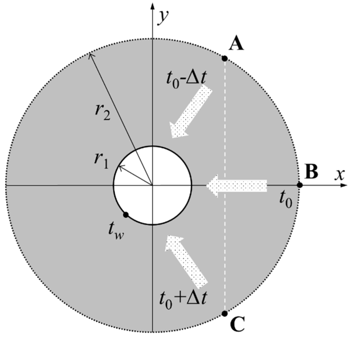
The heat conduction relationship for the cross section of the Heat-Regulating Ring is analyzed, as shown in
Figure 1. The dark part in the figure is the Heat-Regulating Ring, and the white part is the tunnel. The rock mass at different depths has different original rock temperatures. Considering the concept of a geothermal temperature increase rate, the original rock temperatures at different depths can be considered as linearly increasing with depth [
31,
32]. In the figure, the original rock temperatures of the Heat-Regulating Ring at point A above the roadway, point B at the same level, and point C below the roadway are
t0 − ∆
t,
t0, and
t0 + ∆
t, respectively. The two points A and C are in the same vertical direction, and the roadway rock wall temperature is
tw.
According to Fourier’s law, the heat flux is expressed as Equation (1):
where
q is the heat flux density, W/m;
λ is thermal conductivity of the rock, W/(m·K);
dt/
dx is the temperature change rate, where the negative sign indicates that the heat transfer direction is opposite to the temperature increase direction.
The heat flux density generated by the heat conduction from the three points in
Figure 1 to the tunnel wall is shown in the following three equations:
By analyzing the above equations, Equation (2) is obtained.
The upper and lower parts in
Figure 1 are symmetrical in structure, and the average heat flux density of the outer boundary of the Heat-Regulating Ring is equal to the heat flux density generated in the middle direction of the Heat-Regulating Ring (i.e., the heat flux generated from point B to the tunnel wall direction). The heat conduction model of the Heat-Regulating Ring can be simplified to the heat conduction model with the original rock temperature of the outer boundary being a constant value (temperature of point B).
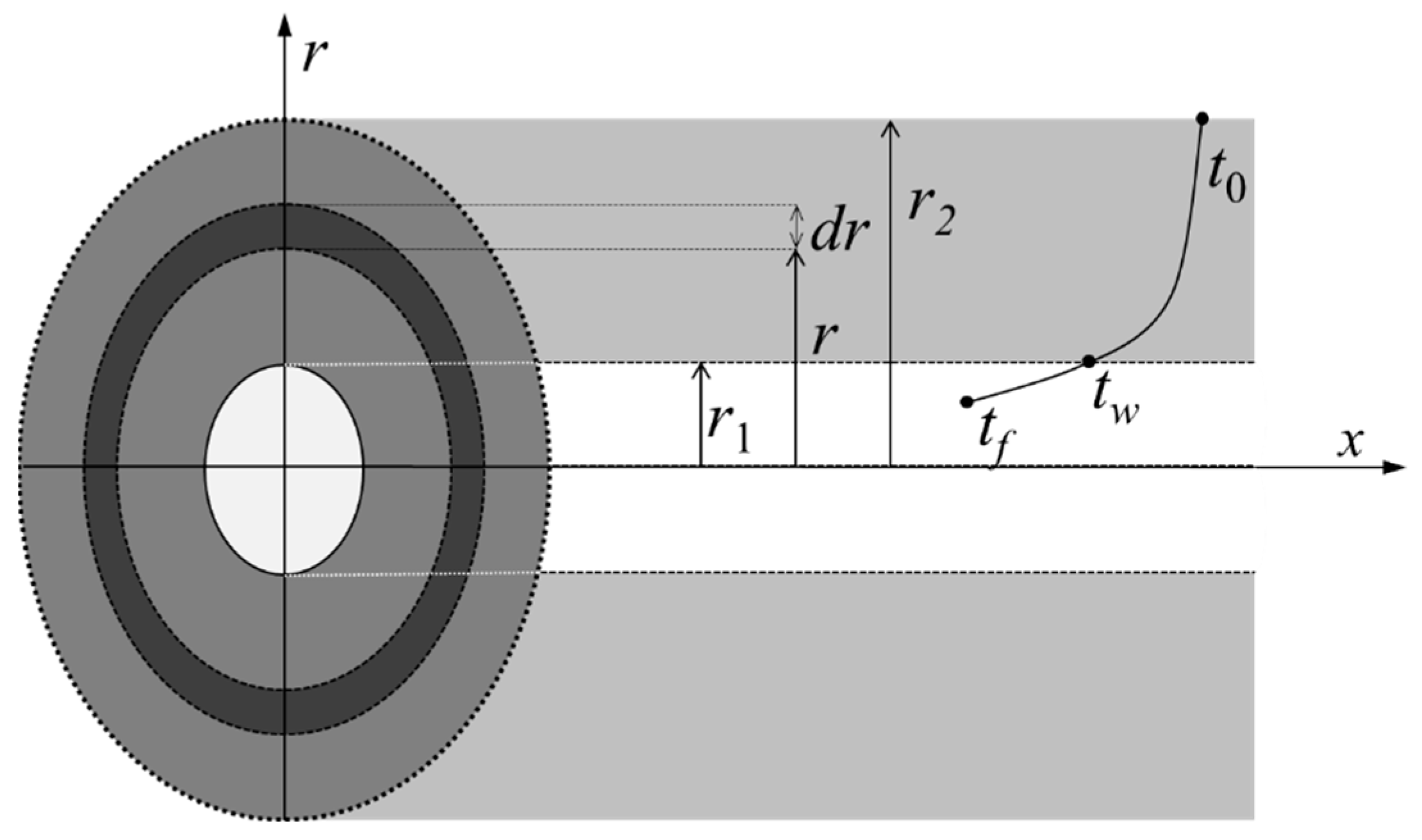
The Heat-Regulating Ring is assumed to be a large cylinder with a ventilation tunnel inside and thermal boundary condition of constant temperature of raw rock outside. The ventilation tunnel is a circular tunnel, the tunnel radius is
r1, the Heat-Regulating-Ring radius is
r2, the original rock temperature is
t0, the rock wall temperature is
tw, and the tunnel air temperature is
tf, as shown in
Figure 2.
After a sufficient ventilation time, the heat conduction of the cross-section of the Heat-Regulating Ring is a one-dimensional heat conduction problem. The heat conduction differential equation and the corresponding boundary conditions are as follows:
The solution of Equation (3) by continuous integration is shown in Equation (4):
where the
c1 and
c2 depend on boundary conditions. Substituting boundary conditions into the equation, the temperature distribution at radius
r is obtained as shown in Equation (5).
Derivating the above equation, the following equation is obtained:
Substituting the above equation into Fourier’s law translates into Equation (6).
From Equation (6), it can be seen that the heat flux density at different radii is inversely proportional to the radius. The heat transfer form in the Heat-Regulating Ring is heat conduction, and the heat transfer forms in the roadway rock wall are heat convection and heat radiation. Without considering the action of water, O2 and N2 in the air, as diatomic gases, basically do not participate in heat radiation, and only the influence of heat convection should be considered in the heat dissipation of the mine-surrounding rock.
The heat flux density of the convective heat transfer from rock walls can be expressed as Equation (7):
where
h is surface heat transfer coefficient, W/(m
2·K).
In the case of the steady-state heat conduction, the heat flux density at the rock wall is equal, i.e.,
q =
qd. Combining Equations (6) and (7), the following equation is obtained (note that in Equation (6),
r =
r1):
Further simplification yields Equation (8).
Equation (8) is the formula for calculating the Heat-Regulating-Ring radius. It can be seen from Equation (8) that the Heat-Regulating-Ring radius is related to the thermal conductivity
λ of the rock, the surface heat transfer coefficient
h of the tunnel, the radius of the ventilation tunnel
r1, the original rock temperature
t0, the rock wall temperature
tw, and the air temperature
tf. As shown in
Figure 2, in the
x direction, i.e., the ventilation direction of the tunnel, the air temperature and the rock wall temperature rise continuously due to the heat transfer temperature, and the radius
r2 of the Heat-Regulating Ring may also change according to Equation (8).
Due to the limitation of experimental conditions, Equation (8) is verified with field experiments and numerical simulation experiments. In the numerical simulation experiment, the Heat-Regulating-Ring radius and temperature variation are tested under different tunnel radius and ventilation parameters.
3. Validation of Experimental Data
In order to eliminate the interference of mine cars, the high-temperature and -humidity area without mine cars was selected as the test site. The test data of the original rock temperature at −662 m in Xiadian Gold Mine was selected to verify the results. The field experiment has obtained the research permission of Xiadian Gold Mine.
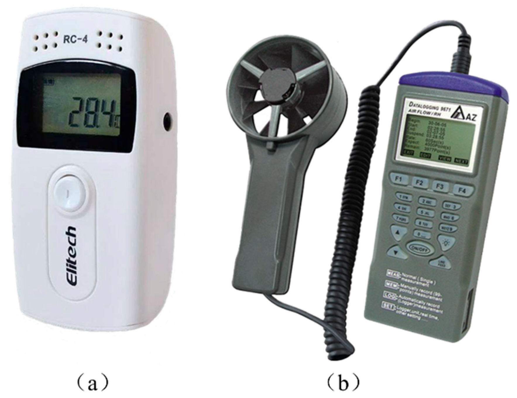
The original rock-temperature-measuring instrument is a single-point digital thermometer, the instrument model is CX-WDJ 200 LCD (Shanghai Innovation Instrument Co., Ltd., Shanghai, China), and the measuring range is −50~+200 °C; the measurement error is 0.1 °C, as shown in
Figure 3a. Since the radius of the Heat-Regulating Ring is generally not more than 30 m, the rock-drilling depth is set as 30 m, and the temperature of the measuring point is taken as the original rock temperature, as shown in
Figure 3b. Under normal ventilation conditions, after drilling for 48 h, the thermometer is bound with the steel bar, and the steel bar goes deep into the hole for the temperature measurement. When measuring, measure point by point from outside to inside, arrange a measuring point every 2.5 m, record the data after the reading of the measuring instrument is stable, and collect the air flow temperature and wind speed data in the roadway near the measuring point.
During the experiment, a temperature and humidity recorder (The instrument model is RC-4, Jiangsu Jingchuang Electric Co., Ltd., Xuzhou, China) was used to record the temperature and relative humidity changes in the environment, with a temperature range of −30~60 °C and the relative humidity range of 0~99%, the measurement error is 0.1 °C, as shown in
Figure 4a. Use an anemometer (The instrument model is AZ9651, Taiwan Hengxin Instrument Co., Ltd., Taiwan, China) to record the wind speed and air pressure, with the wind speed ranging from 0 to 45 m/s; the measurement error is 0.1 m/s, as shown in
Figure 4b. Before the experiment, the test instruments were calibrated. During the experiment, the instruments were placed in a stable environment strictly according to the requirements of instrument use.
The arch tunnel has a sectional area of 23.2 m
2, the thermal conductivity
λ= 3 W/(m·K), the original rock temperature
t0 = 30.8 °C, the rock wall temperature
tw = 30.4 °C, the air temperature
tf = 29.9 °C, the convective heat transfer coefficient
h = 0.6 w/(m
2·K), and
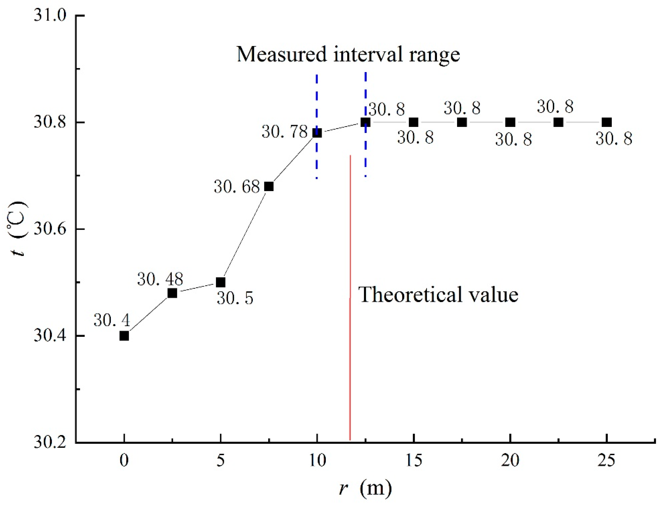
r2 = 11.84 m, calculated by substituting Equation (8). The measured original rock temperature and the depth of the measuring point are shown in
Figure 5.
It can be seen from
Figure 5 that the rock mass temperature increases correspondingly with the increase in the depth of the measuring point. After the depth of the measuring point reaches 12.5 m, the rock mass temperature remains unchanged at 30.8 °C. It can be seen that the original rock temperature for this section of roadway is 30.8 °C. According to the depth of the measuring point and the temperature change in the original rock, it can be known that the radius of the Heat-Regulating Ring is between 10 m and 12.5 m, and the theoretical value calculated according to formula is 11.84 m in the range of the measured interval. The theoretical value is consistent with the experimental value. Equation (8) can be used to calculate or predict the radius of the Heat-Regulating Ring.
4. Numerical Simulation Experiments
4.1. Model and Parameter Setting of Heat-Regulating Ring
ANSYS 2023 R1 is selected as the numerical simulation platform (The software provided by USTB, Beijing, China). Simulating experiments are carried out on the heat conduction of the Heat-Regulating Ring under various tunnel radii and ventilation parameters. In the model, the radius of the rock mass is 50 m, the radius of the roadway is 0.5~4 m, and the length of the roadway is 500 m. As shown in
Figure 6, the numerical model diagram of the roadway radius is 2 m.
The “mesh” software is used to generate meshes. Tetrahedron mesh division method is mainly adopted, with a mesh number of 431220 and a node number of 457846. The mesh independence analysis is as follows: For a model with a radius of 2 m, take three points of the exit section (500, −0.5, 0) (500, 0, 0) (500, 0.5, 0). When the total numbers of grids are 431220, 474164, 597220, 714820, and 1467336, respectively, under the condition of a wind speed of 5 m/s and a ventilation time of 1800 days, the temperature value of three points changes very little, and the difference is less than 0.1 °C, which indicates that the number of grids has little influence on the calculation results. It can be considered that the grid number of 431220 has reached the grid independence, so the grid number of 431220 is selected as the calculation grid.
Parameter settings are shown in
Table 1.
4.2. Influences of Tunnel Section on Heat-Regulating-Ring Radius
In the numerical simulation experiments, the tunnel sections are set as circle, rectangle, and arch, respectively, and the influence of different section types on the radius of the Heat-Regulating Ring is tested. As shown in
Figure 7, the value of R2 in the figure is the average value at 100 m, 250 m, and 400 m from the entrance in the tunnel model.
The total ventilation time is 1800 days, the Heat-Regulating-Ring radii of the circular section, rectangular section, and arch section are 7 m, 8.5 m, and 8.3 m, respectively, when the ventilation time is 30 days; the Heat-Regulating-Ring radii of the circular section, rectangular section, and arch section are 16.9 m, 18.2 m, and 17.6 m, respectively, when the ventilation time is 300 days. When the ventilation time is 600 days, the three values are 21.6 m, 22.2 m, and 21.9 m, respectively, and when the ventilation time is 900 days, the three values are 25.1 m, 25.1 m, and 25.3 m, respectively. At this time, the influence of the section change on the Heat-Regulating-Ring radius is very small and can be ignored.
As can be seen from the data change in
Figure 7, if the ventilation time is long enough, the tunnel section shape has no effect on the radius of the Heat-Regulating Ring.
4.3. Effects of Ventilation Time on Heat-Regulating-Ring Radius
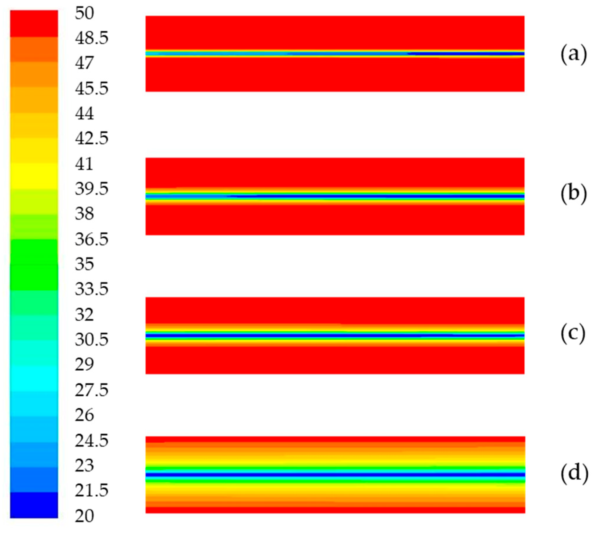
The wind speed of 5 m/s, the radius of Heat-Regulating Ring
r1 of 2 m, and the change in Heat-Regulating-Ring radius in the process of ventilation for 1800 days are selected for the explanation.
Figure 8a–d show the temperature field distribution of the Heat-Regulating Ring at 30 days, 180 days, 360 days, and 1800 days, respectively. It can be seen intuitively from
Figure 8 that the radius of the Heat-Regulating Ring changes slowly with the ventilation time, and this radius change can only be reflected after a sufficient ventilation time.
After 1800 days (nearly 5 years) of ventilation, the radius of the Heat-Regulating Ring increases below 0.1 m every 30 days, and the daily variation amplitude is less than 0.0034 m. The Heat-Regulating Ring is relatively stable. At this time, the Heat-Regulating Ring can be considered as relatively stable, and the heat conduction problem of the Heat-Regulating Ring can be solved by the steady-state heat conduction. After 1800 days of ventilation, the radius of the Heat-Regulating Ring is 27.9~28.4 m along the distance of the 500 m long roadway. It can be seen that the radius of Heat-Regulating Ring after a long-enough ventilation varies little along the roadway trend, which can be ignored in engineering calculation.
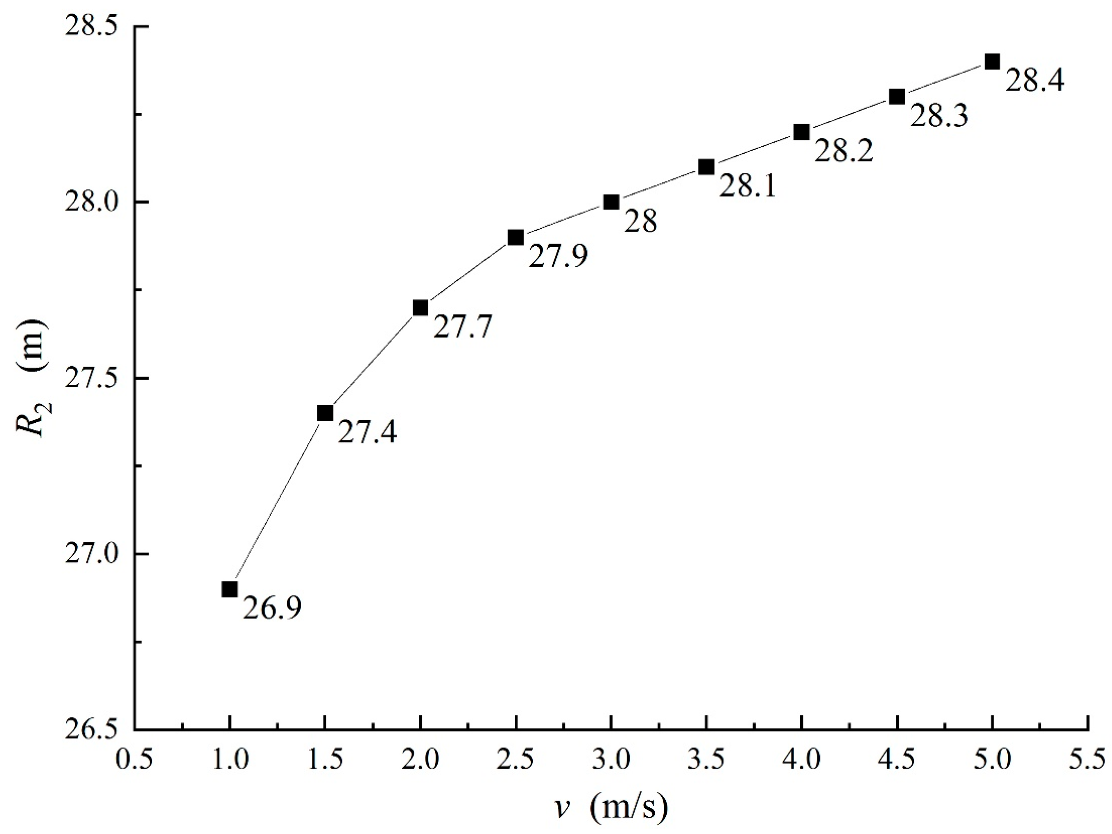
4.4. Effects of Wind Speed on Heat-Regulating-Ring Radius
Change the ventilation wind speed, adopt the same tunnel model (
r1 = 2 m), and collate the experimental data to form
Figure 9 after the same simulation time of 1800 days.
As can be seen from
Figure 9, the wind speed increases from 1 m/s to 5 m/s, and the radius of the Heat-Regulating Ring increases from 26.9 m to 28.4 m. When the wind speed reaches 2.5 m/s, the radius of the Heat-Regulating Ring increases by only 0.1 m. In a certain ventilation time, the larger the wind speed, the larger the radius of the Heat-Regulating Ring, and the radius increase gradually weakened.
According to Equation (8), the theoretical value of the Heat-Regulating-Ring radius under different wind speeds is verified to be consistent with the simulated experimental value. Under different wind speeds, the thermal conductivity λ = 3 W/(m·K), tunnel radius r1 = 2 m, raw rock temperature t0 = 50 °C, air temperature tf = 20 °C, and tw are determined according to simulation experimental data.
The surface heat transfer coefficient
h is calculated with reference to Equation (9) [
30]:
where
λ is the thermal conductivity of the fluid, W/(m·K);
D is the characteristic length, m;
Nu is the Nusselt number;
Re is the Reynolds number;
Pr is the Planck number.
The surface heat transfer coefficient
h reflects the influence of different wind speeds. Theoretical values are calculated according to Equation (8), and numerical simulation experimental values are shown in
Table 2. In the table, the
r2 refers to the theoretical value calculated according to Equation (8), the
R2 refers to the experimental value of numerical simulation, and
δ is the relative error,
δ = (
R2 −
r2)/
R2.
Comparing r2 with R2, it is found that the difference between r2 and R2 is less than 1 °C, and the relative error is between −7.8% and 3.6%. The radius of the Heat-Regulating Ring calculated by Equation (8) basically accords with the experimental results.
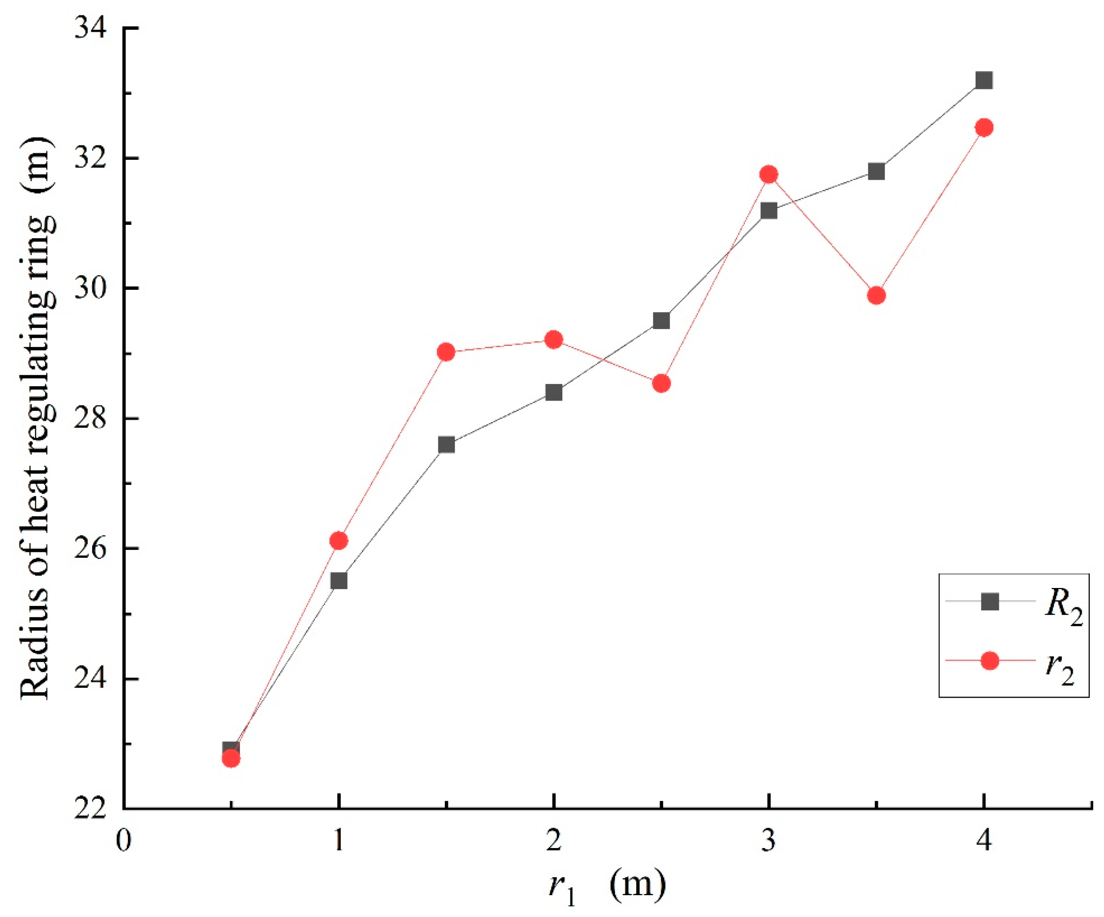
4.5. Influence of Tunnel Radius on Heat-Regulating-Ring Radius
When the wind speed is 5 m/s and the ventilation time is 1800 days, the theoretical value and experimental values of the Heat-Regulating-Ring radius under different tunnel radii are shown in
Figure 10.
When the tunnel radius r1 is 0.5 m, the theoretical calculation value r2 of the Heat-Regulating-Ring radius is 22.99 m, and the numerical simulation experimental value R2 is 22.9 m. When the tunnel radius is 1 m, the r2 and R2 are 26.12 m and 25.5 m, respectively; when the tunnel radius is 3.5 m, the r2 and R2 are 29.9 m and 31.8 m, respectively; the difference between them reaches 1.9 m, and the difference reaches the maximum; when the tunnel radius is 4 m, the r2 and R2 are 32.47 m and 33.2 m, respectively, and the difference between them reaches 0.73 m. It can be seen from the data in the figure that when the radius of the roadway increases, the Heat-Regulating-Ring radius will increase accordingly, but if the radius of the roadway changes slightly, the influence on the Heat-Regulating-Ring radius is very small, which can be ignored in engineering calculations. Comparing the theoretical value r2 with the experimental value R2, the difference between them is basically within the acceptable range. Under the condition of different tunnel radii, the Heat-Regulating-Ring radius calculated by Formula (8) basically accords with the experimental results.
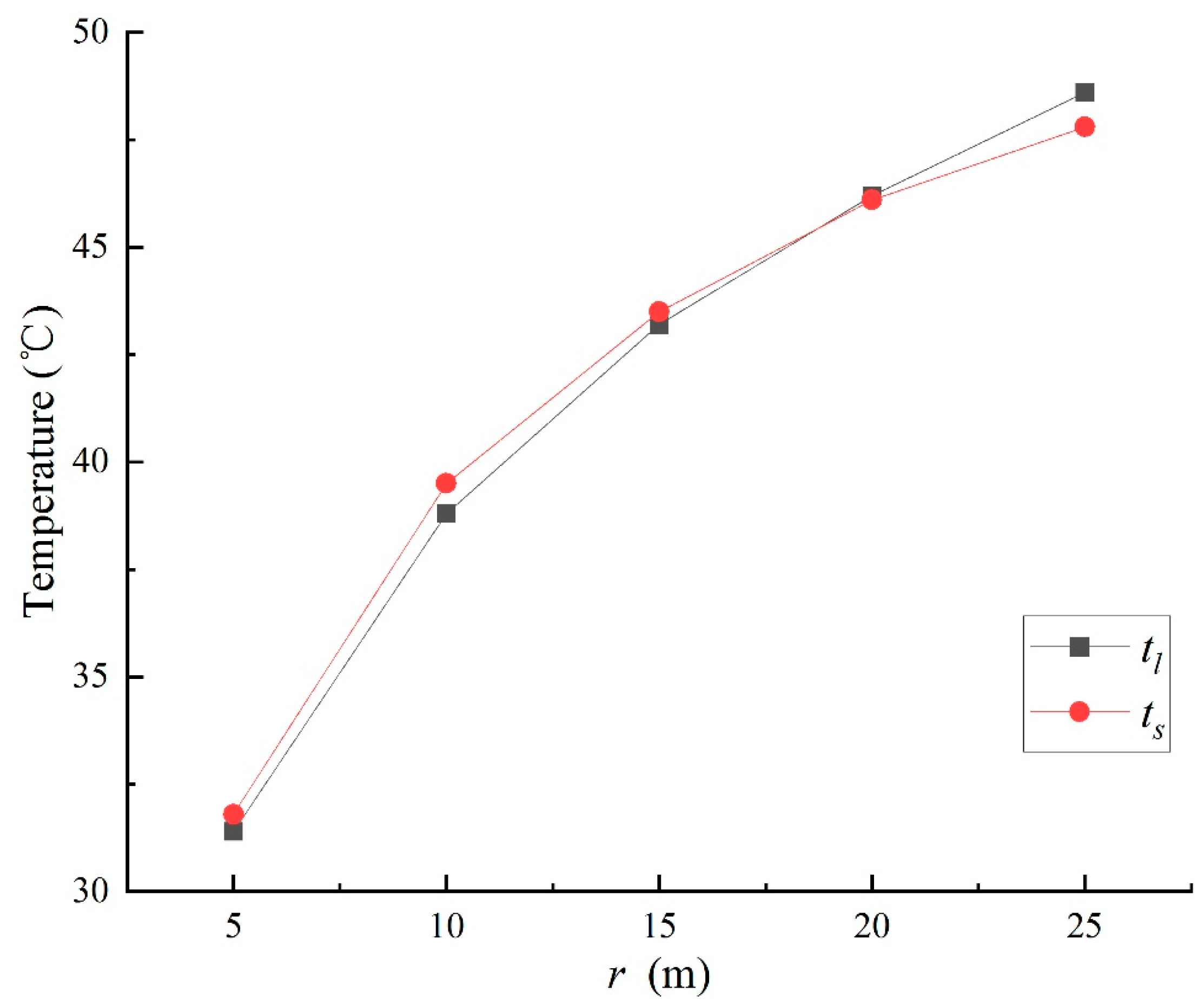
4.6. Calculation of Heat-Regulating Ring Internal Temperatures
Equation (5) reflects the relationship between the rock mass temperature and other parameters at a certain depth in the Heat-Regulating Ring, which can be used to calculate rock mass temperature at a certain point. The following is verified according to the numerical simulation results, where r1 < r < r2: After the ventilation of 5 m/s for 1800 days, the theoretical value tl and the experimental value ts at different r positions in the Heat-Regulating Ring are verified, where t0 = 50 °C, tw = 21.6 °C, r1 = 2 m, and r2 = 28.4 m.
At the rock mass 5 m, 10 m, 15 m, 20 m, and 25 m away from the tunnel center, the
tl values are 31.4 °C, 38.8 °C, 43.2 °C, 46.2 °C, and 48.6 °C, respectively; the
ts values are 31.8 °C, 39.5 °C, 43.5 °C, 46.1 °C, and 47.8 °C, respectively; the maximum difference between
tl and
ts is 0.8 °C, and the difference between
tl and
ts is very small. Analyzing the data in
Figure 11, the theoretical temperature value and the experimental temperature value at different
r positions are very close to each other, and the internal temperature calculations of the Heat-Regulating Ring using Formula (5) are very close to the numerical simulation’s experimental values.
The values calculated by Equations (5) and (8) give results closer to the experimental values. The thermal conductivity λ of the rock, the surface heat transfer coefficient h of the tunnel, the radius r1 of the ventilation tunnel, the original rock temperature t0, the rock wall temperature tw, and the air temperature tf in the two equations can be measured or obtained by consulting geological and hydrological data. When using the two equations, the values of λ, h, t0, tw, and tf must be accurate to ensure that the results are as close to the actual state of the Heat-Regulating Ring as possible. Equations (5) and (8) are derived from the fundamental theory of heat transfer and are therefore of general applicability.
5. Conclusions
Considering the Heat-Regulating Ring with a sufficient ventilation time as a steady-state heat conduction model, the temperature and radius of the Heat-Regulating Ring are proposed. Equations (5) and (8) are verified with measured data and numerical simulation experiments. The theoretical results are close to the actual heat conduction of the Heat-Regulating Ring, and the formula has theoretical and practical value.
With the increase in the ventilation wind speed, the Heat-Regulating-Ring radius will increase accordingly. If the ventilation time is long enough, the Heat-Regulating-Ring radius will be slightly affected by the ventilation wind speed; with the increase in the ventilation wind speed, the internal temperature of the Heat-Regulating Ring will decrease correspondingly, and the decreasing amplitude will gradually decrease with the increase in the Heat-Regulating-Ring depth; when the wind speed reaches a certain value, although the wind speed is still increasing, the temperature value of the Heat-Regulating Ring is basically unchanged or the changing amplitude is very small.
The Heat-Regulating-Ring radius, which has experienced sufficient ventilation for a long time varies very little along the roadway trend, and this difference can be ignored in engineering calculations. The wind speed increases from 1 m/s to 5 m/s, and the radius of the Heat-Regulating Ring increases from 26.9 m to 28.4 m.
If the ventilation time is long enough, the section shape of the roadway has no effect on the Heat-Regulating-Ring radius. When the wind speed is 5 m/s, after 1800 days of ventilation, the radius of the heat regulation circle along the roadway is 27.9 m to 28.4 m.
When the radius of the ventilation tunnel increases, the Heat-Regulating-Ring radius will increase correspondingly, but if the radius of the ventilation tunnel changes slightly, the influence on the Heat-Regulating-Ring radius is very small, and this influence can also be ignored in engineering calculations.


