Abstract
Micro-nano bubbles (MNBs) are tiny bubbles with diameters ranging from 200 nm to 30 µm. They possess unique physicochemical properties such as a large specific surface area, slow rising velocity, high gas dissolution rate, high mass transfer efficiency, and strong interfacial zeta potential. These properties endow MNBs with great potential in various fields, including water treatment, enhanced oil recovery, medical and health care, and agriculture. This paper systematically reviews the physicochemical properties, generation methods, and applications of micro-nano bubbles. The main production methods include the mechanical stirring, pressurized dissolved gas release, ultrasonic cavitation, venturi injection, electrolysis, etc. The principles, advantages and disadvantages, and optimization strategies of these methods are comprehensively analyzed. In terms of applications, the mechanisms and typical cases of MNBs in enhanced oil recovery, water treatment, mineral flotation, medical drug delivery, and crop yield enhancement are thoroughly discussed. Extensive research has shown that MNB technology is highly efficient, energy-saving, and environmentally friendly. However, improving bubble stability, generation efficiency, and large-scale application remain key directions for future research.
1. Introduction
Microbubbles typically refer to gaseous cavities in aqueous media with diameters ranging from 10 to 15 μm, while ultrafine bubbles below 200 nanometers (nm) are classified as nanobubbles. The intermediate category spanning between microbubbles and nanobubbles is designated micro-nano bubbles (MNBs) [1]. Compared with traditional large bubbles (diameter > 50 mm) and small bubbles (diameter < 5 mm), MNBs have smaller sizes and a more uniform distribution in aqueous media. They exhibit unique physicochemical properties such as large specific surface area, slow rising velocity, high interfacial zeta potential, easy self-pressurization and dissolution, and high mass transfer efficiency. Therefore, their generation methods and surface properties have attracted widespread attention.
The formation of MNBs is a physical phenomenon in gas–liquid two-phase flow, and the core lies in generating stable and controllable tiny bubbles in water. As early as 1970, Bowonder et al. [2] conducted research on bubble generation using porous discs. In 1979, Takahashi et al. [3] proposed the technology of bubble generation by pressurized gas dissolution. In 1991, Ketkar et al. [4] achieved bubble generation by electrolysis. In 2018, Ding, G.D. et al. [5] reported a bubble generation technology using orifice plates and hydro cyclones, which greatly enriched and developed the methods for generating MNBs, including mechanical shearing, ultrasonic, pressurized gas dissolution, and electrolysis methods.
MNB technology has been widely applied in various fields. In water treatment, it can effectively improve the efficiency of flotation and rapidly remove organic pollutants. In the biomedical field, it is used for ultrasonic imaging and drug carriers. In agriculture, it can promote plant nutrient absorption, crop quality, and yield. In the energy sector, MNB oil displacement technology has improved the crude oil recovery rate of low-permeability reservoirs, with the advantages of being environmentally friendly and low-cost.
2. Characteristics of Micro-Nano Bubbles
2.1. Physicochemical Properties of Micro-Nano Bubbles
2.1.1. Small Size
Bubbles are classified based on their diameters. Microbubbles range in size from several millimeters to several centimeters; microbubbles have diameters from tens to hundreds of micrometers; and nanobubbles usually refer to bubbles with diameters from 1 to 100 nm [6], as shown in Figure 1. In 2017, the diameter of a nanobubble was defined as less than 1 µm.
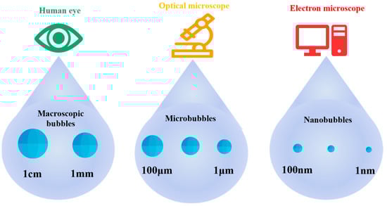
Figure 1.
Classification of bubbles based on diameter.
2.1.2. Large Specific Surface Area
The specific surface area of a bubble refers to the ratio of its total surface area to the volume of the gas it contains, which describes the dispersion degree of the bubble in the liquid and the size of the bubble.
The specific surface area of a bubble can be calculated using Equations (1)–(3) [7].
where Sb is the specific surface area of the bubble (m2/m3); r is the radius of the bubble (m); A is the total surface area of the bubble (m2); V is the volume of the bubble (m3).
It can be seen from the above equations that, under the same bubble volume, the specific surface area Sb is inversely proportional to the radius r. That is, the smaller the radius r, the larger the specific surface area Sb. For example, the specific surface area of a microbubble with a radius of 1 µm is 1000 times that of a conventional bubble with a radius of 1 mm.
2.1.3. Slow Rising Velocity in Water
MNBs have a relatively long residence time in the water because their small size slows down their rising velocity, making it difficult for them to quickly float to the surface. The rising velocity of MNBs can be expressed using Stokes’ law, where the rising velocity of the bubble is directly proportional to its size and inversely proportional to the viscosity of the surrounding liquid.
where d is the diameter of the bubble (m); g is the gravitational acceleration constant; μl is the viscosity of the surrounding liquid (Pa·s); ρg is the density of the bubble (kg/m3); ρl is the density of the surrounding liquid (kg/m3).
In 2020, Swart’s research [8] found that when the diameter of microbubbles is in the range of 10 to 120 µm, the rising velocity is 1 to 12 mm/s. For a nanobubble, the rising velocity of a nanobubble with a diameter of 100 nm is 2.7 nm/s, indicating a longer residence time and slower rising velocity.
2.1.4. High Bubble Surface Zeta Potential
Zeta potential (ζ-potential) is an important parameter characterizing the surface charge state of bubbles in a dispersed system. It represents the potential difference at the sliding interface between the bubble and the surrounding medium and is affected by the solution pH, ionic strength, electrolyte type, and surface properties [9], as shown in Table 1.

Table 1.
Different factors affecting zeta potential.
According to the Smoluchowski equation [13], the zeta potential can be determined from the electrophoretic mobility, as shown in Equation (5):
where η is the viscosity of the liquid (kg·m−1·s−1); μ is the electrophoretic mobility (m2·s−1·V−1); ε is the dielectric constant of the liquid (kg−1·m−3·C2).
The zeta potential of MNBs is influenced by the solution pH, ion strength, electrolyte type, and bubble surface properties, which determine the surface charge state and density of the bubble. Takahashi [14] found that the bubble charge is affected by the pH value and is usually negatively charged, but positively charged under strong acidic conditions. Based on this, Hewage’s [15] research showed that the higher the absolute value of the zeta potential, the better the bubble stability owing to the strong electrostatic repulsion.
2.1.5. Easy Self-Pressurization and Dissolution
The self-pressurization and dissolution characteristic of MNBs refers to the process where the bubble wall gradually thins and eventually dissolves due to the internal pressure being higher than the external environmental pressure. Matsumoto’s [16] molecular dynamics study found that as the bubble size decreases, the tensile stress experienced by the liquid increases. Formula 6 can be derived from the Young–Laplace equation, the internal pressure of micro-nano bubbles increases sharply with the decrease in bubble size, making it difficult for MNBs to remain stable under normal pressure [1].
where ΔP is the pressure difference between the internal bubble and the surrounding bulk liquid (Pa); σ is the surface tension of the liquid (N/m); and d is the diameter of the bubble (m).
As the bubble radius r decreases, the specific surface area Sb increases, and the increase in σ leads to higher internal pressure, making the bubble more likely to dissolve in water. Therefore, during the self-pressurization process, the gas inside the bubble continuously dissolves into the water, increasing the gas solubility in the liquid.
2.1.6. Strong Mass Transfer Efficiency
The mass transfer efficiency of a bubble refers to its ability to facilitate the transport of substances in the liquid. In the mass transfer process of bubbles, the mass transfer coefficient KL is an important parameter, which measures the mass transfer efficiency through the bubble interface per unit time. The larger the KL, the better the mass transfer efficiency.
Mass transfer efficiency is usually characterized by the mass transfer coefficient or mass transfer unit number. The following are two common definitions [17]:
(1) Mass transfer coefficient formula.
where D is the diffusion coefficient of the solute in the liquid phase (m2/s); tc is the contact time between the bubble and the liquid (s).
(2) Mass transfer flux formula.
where J is the mass transfer flux mol/(m2·s); kL is the liquid-phase mass transfer coefficient (m/s); C* is the saturation concentration at the gas–liquid interface (mol/m3); Cb is the bulk liquid concentration (mol/m3).
Due to their larger contact area and long-term interaction with the liquid, the mass transfer efficiency of MNBs is significantly higher than that of conventional bubbles. Moreover, the lower surface tension of microbubbles promotes their close contact and fusion with the liquid, shortening the mass transfer distance and thereby enhancing the mass transfer efficiency [18].
2.2. Measurement Methods for Micro-Nano Bubbles
MNBs are small in size and complex in properties, making it challenging for traditional measurement methods to accurately characterize them. The exploration of efficient and reliable measurement methods for micro-nano bubbles is crucial for gaining an in-depth understanding of their characteristics and advancing application development. The primary measurement techniques are summarized in Table 2.
Table 2.
Main measurement methods for micro-nano bubbles’ characteristic parameters.
3. Generation Devices for Micro-Nano Bubbles
Micro-nano bubble generation devices are the core equipment for generating MNBs. Their technical principles and generation methods directly affect the size, concentration, and stability of the bubbles. According to the different generation principles, micro-nano bubble generation devices can be divided into the following categories: mechanical shearing, pressurized gas dissolution, cavitation effect, electrochemical, and micro-porous dispersion methods.
3.1. Mechanical Shearing Methods
Mechanical shearing methods generate bubbles by shearing gas with mechanical force. A typical device is the mechanical stirring type. The early mechanical stirring method used a rotating disc device to prepare microbubbles through high-speed shearing (Figure 2) [21]. However, it suffered from low efficiency and poor bubble stability, and it relied on surfactants or environmental control [22,23]. In 2017, Etchepare et al. [24] made improvements by introducing a centrifugal multiphase pump and coupling it with cavitation effects; the system enabled stable generation of highly monodisperse nanobubbles (150–250 nm). Bubble production rate increased progressively with cycling frequency, reaching a peak concentration of 4.1 × 10⁹ bubbles/mL after 29 operational cycles (equivalent to 61 min) under optimized conditions of 5 bar operating pressure and reduced surface tension (49 mN/m).
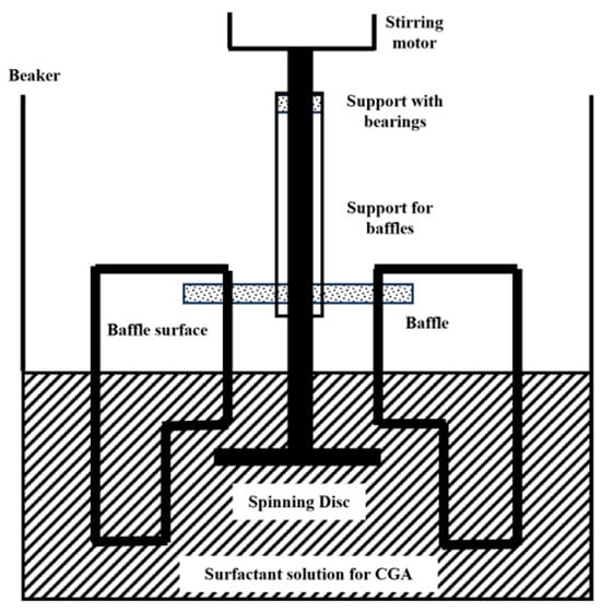
Figure 2.
Device for preparing nanobubbles by mechanical stirring [22].
Although the mechanical agitation method is a simple and easy approach for generating micro-nano bubbles, featuring a straightforward apparatus and low manufacturing cost, it requires the presence of surface-active agents acting as foaming agents. Consequently, there exists difficulty in the direct generation of micro-nano bubbles in water. Additionally, this method faces issues such as imprecise control of bubble size and relatively short bubble stability time. While mechanical agitation is commonly employed for preparing micro-nano bubbles in laboratory settings, it is less frequently utilized in large-scale industrial production.
3.2. Pressurized Gas Dissolution Methods
Pressurized gas dissolution methods generate micro-nano bubbles by utilizing changes in gas–liquid pressure to dissolve and release gases. A typical method is the gas dissolution and release method. The operational principle of the dissolved air release micro-nano bubble generator is depicted in Figure 3. This method dissolves gas in a pressurized gas dissolution tank and then releases the gas through a depressurization device, causing the gas to precipitate and form gas clusters. Under the action of shear force, these clusters split into micro-nano bubbles with diameters of 20 to 100 µm.
In 2016, Shi Yulong [25] reported that energy consumption could be reduced by optimizing the gas–liquid pressure differential or adding surfactants (e.g., sodium oleate). That same year, Azevedo et al. [26] successfully generated highly uniform nanobubbles (150–200 nm, distribution ranging 50–300 nm) through the combination of low pressure (<3 bar) and low surface tension (49 mN/m). The bubble generation density (not direct frequency) is modulated by the gas-to-liquid ratio and saturation pressure, achieving a peak concentration of 1.6 × 10⁹ bubbles/mL. Both size and concentration exhibited no significant changes over a 14-day period [26].
Currently, the dissolved air release method is primarily employed in industrial wastewater treatment and oily wastewater treatment processes. However, it presents several limitations, including the requirement for auxiliary surfactants, high energy consumption, complex equipment requirements, and the potential discontinuity of micro-nano bubble generation.

Figure 3.
Pressurized gas MNB generation device [27].
Figure 3.
Pressurized gas MNB generation device [27].

3.3. Cavitation Effect Methods
Cavitation effect methods generate localized low-pressure areas in the liquid through cavitation, causing dissolved gases to precipitate and form bubbles. This category mainly includes hydraulic cavitation and acoustic cavitation. Hydraulic cavitation uses the localized low-pressure region generated in high-speed flowing or strongly turbulent liquids to draw in gases and form micro-nano bubbles. Typical experimental devices include venturi tube devices, jet-type bubble generators, and swirl-type bubble generators. Acoustic cavitation uses the cavitation effect produced by ultrasonic waves propagating in the liquid to break the gas in the liquid and form micro-nano bubbles. A typical method is ultrasonic cavitation.
The Venturi tube device utilizes the fluid dynamic characteristics of its geometric structure (converging section, throat, and diverging section). The high speed and low pressure at the throat cause gases to precipitate and rupture into micro-nano bubbles (down to below 10 µm). The bubble size can be significantly reduced by optimizing the divergence angle [28] (Figure 4), introducing vortex design [29], or combining Tesla valve structures [30]. Experimental findings reveal that an increase in liquid velocity substantially reduces bubble size while enhancing size uniformity, whereas elevated gas velocity broadens size distribution. The swirl design achieves a 48% reduction in Sauter mean diameter (d32), narrows the size distribution (40% decrease in standard deviation), and triples bubble productivity. In 2024, Li et al. [30] optimized the Venturi tube design by incorporating the Tesla valvular principle, as illustrated in Figure 5. This configuration exhibits structural simplicity and compactness while effectively reducing bubble dimensions. Particularly, the symmetrical configuration of Tesla valves elevates the proportion of target-sized bubbles to 90%. However, the bubble distribution is easily affected by fluid properties and geometric parameters, and there remains a lack of an accurate prediction model.
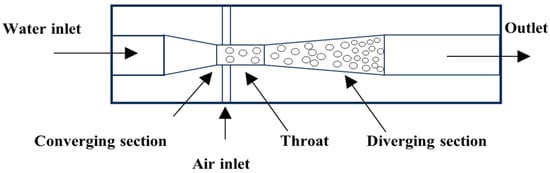
Figure 4.
Venturi tube nozzle-type bubble generator [28].
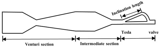
Figure 5.
Venturi tube combined with Tesla valve [30].
The swirl-type generator operates through the synergistic action of centrifugal force and shear force. The performance can be continuously improved by structural optimization, and the bubble size distribution can be changed by adjusting the outlet pressure. However, increasing the pressure tends to generate more large-sized bubbles [31]. When the characteristic parameter K of the vortex chamber structure increases from 3.2 to 4.8 [32], the generation efficiency is significantly improved, the gas-to-liquid ratio (K) of 6.4 achieves the maximum ratio (optimizing energy efficiency), while a K value of 8.0 is suitable for high-throughput scenarios. Generating minimal bubble sizes (271 μm) requires K = 12, although this necessitates compromising vacuum level and aerating capacity. Increasing the K value can expand processing capacity, but it leads to a wider bubble size distribution.
In 2018, Kim et al. [33] investigated a vortex-driven micro-nano bubble generator featuring an internal baffle configuration, as depicted in Figure 6. A four-spiral channel structure can achieve high-density microbubbles, through the cascaded vortex shear and swirl focusing effects, the volume concentration of sub-micron bubbles is significantly enhanced from a low level (0.0001 mL/mL) to approach that characteristic of microbubbles (0.01–0.1 mL/mL), all without requiring external ultrasonic intervention. In 2022, Wu et al. [34] investigated a vortex-driven micro-nano bubble generator featuring an internal baffle configuration, as depicted in Figure 6. Subsequent innovations, such as adding baffles to weaken the vortex and enhance fragmentation, reduce the bubble size to 38–55 µm (increasing the liquid flow velocity can further reduce the size). The use of variable-pitch guide vanes and a central column to enhance shear resulted in the generation of bubbles with a size of 301 nm [35].
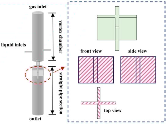
Figure 6.
Swirl-type micro-nano bubble generator with baffles [34].
The jet-type micro-nano bubble generator consists of a nozzle, suction chamber, throat tube, and diffuser [36] (Figure 7). Studies have shown that the bubble size, uniformity, and generation efficiency are affected by the nozzle structure, fluid parameters, and gas–liquid interactions. The bubble diameter reaches a minimum when the throat-to-nozzle distance is 1 to 2 times the nozzle outlet diameter, and a high bubble density with steady flow characteristics is observed at this stage. Increasing the outlet throat tube diameter from 1 mm to 5 mm increases the average bubble diameter from 0.5 mm to 2.0 mm [37].
Further optimization of the structure can improve bubble generation efficiency. In 2023, Hu, X. et al. [38] redesigned a vortex-driven bubble generator by incorporating flow-disturbing cylinders in the throat section, establishing a Kármán vortex street configuration, which enhances turbulent intensity to promote bubble fragmentation. Additionally, in 2020, Tian et al. [39] investigated the influence of downcomer length, liquid dynamic viscosity, and volumetric flow rate on bubble characteristics in jet-driven bubble generators; in low-viscosity liquids, an increase in viscosity reduces the energy dissipation rate, leading to larger bubbles. In contrast, increasing the liquid flow rate improves the energy dissipation rate, reducing the Sauter mean diameter of bubbles. This confirms the key role of high shear force in micro-fine effects.

Figure 7.
Jet-type micro-nano bubble generator [40].
Figure 7.
Jet-type micro-nano bubble generator [40].

The technology can achieve high gas holdup and uniform distribution of small-sized bubbles through optimization of nozzle design and operating conditions, with the advantages of high oxygen transfer efficiency and low energy consumption. It is widely used in water treatment and chemical engineering fields.
The ultrasonic generator [41] uses ultrasonic waves to create alternating positive and negative pressure zones in the liquid, causing gas nuclei to expand into cavitation bubbles in the negative pressure zone and then collapse in the positive pressure zone to generate micro-nano bubbles; the experimental setup is schematically illustrated in Figure 8. By adjusting the ultrasonic power, probe orifice size, and gas flow rate [42,43], the bubble size can be partially controlled, generating micro-nano bubbles with diameters ranging from 50 nm to 50 µm [44,45]; for instance, a 4 mm probe orifice diameter under 100 W ultrasonic power input demonstrates maximum micro-nano bubble generation efficiency. In a stable acoustic field, a single bubble can undergo periodic oscillations over hundreds of cycles. However, under high-power conditions or in non-degassed liquids, the coexistence of multiple bubbles results in mutual interference, leading to significant deterioration in uniformity.
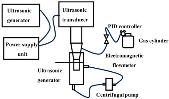
Figure 8.
Hollow cylindrical ultrasonic probe device [43].
The concentration and size of nanobubbles dynamically change with ultrasonic time and can be uniformly distributed in water for up to 24 h. The method has a simple device structure and is applicable to a wide range of media. The high-energy cavitation effect can also endow bubbles with high activity. However, it has problems such as high energy consumption, and prolonged ultrasonic exposure is prone to induce stability degradation and other issues, making it difficult to meet the needs of large-scale production.
3.4. Electrochemical Methods
Electrochemical methods generate micro-nano bubbles via gas production through electrochemical reactions on the electrode surface [46]. Electrolysis is the most commonly used method. By applying a voltage to the electrode, water molecules are electrolyzed to produce H2 and O2 gases. These gases nucleate on the electrode surface and gradually detach to form bubbles; the experimental setup is schematically illustrated in Figure 9.
Studies have shown that bubble size can be precisely controlled by adjusting electrolysis parameters [47]. For instance, increasing the voltage to reduce the bubble diameter [48], with a 0.3 mm electrode, bubbles generated at 25 V exhibit a diameter of approximately 45 μm, whereas at 4 V, the bubble diameter is about 120 μm. In 2019, Rameshkumar et al. [49] demonstrated that copper rod electrodes generate nanobubbles (264–293 nm) in distilled water, with bubble generation rate modulated by applied voltage. Increased voltage enhanced production rates proportionally. Electrode material optimization improves bubble generation rate and uniformity; for instance, fabric electrodes immobilize bubble nucleation sites, achieving 30–40% higher volumetric production rates per unit area than planar electrodes. This method offers advantages including external gas source independence and controllable bubble dimensions. However, electrode corrosion resistance and reaction efficiency stability remain technical challenges. In 2012, Liu et al. [50] investigated electrode-dependent bubble generation dynamics, revealing that porous hydrophilic electrode surfaces yield higher bubble densities and faster generation rates. Further optimization of bubble distribution was achieved through electrolyte concentration and property modifications (e.g., NaCl solutions or acidified water). Increasing NaCl concentration from 0.41% to 0.83% doubled bubble quantity while reducing mean diameter by approximately 30% [51].

Figure 9.
Schematic diagram of a microbubble generation device by electrolysis [52].
Figure 9.
Schematic diagram of a microbubble generation device by electrolysis [52].

Currently, laboratory-scale fabrication of bubbles spanning the sub-micrometer to hundred-micrometer range has been achieved through tailored electrode designs (e.g., textile-type and metallic sphere electrodes). These systems demonstrate distinct application advantages in microfluidic devices and specialized industrial scenarios. Future research should prioritize optimization of electrolytic processes and enhancement of bubble performance characteristics to enable broader application scopes.
3.5. Micro-Porous Dispersion Methods
The principle of the micro-porous dispersion method for preparing micro-nano bubbles is to disperse gas into the liquid through micro-porous structures to form tiny bubbles. The core lies in utilizing the fine pore size and surface tension of micro-porous materials to segment the gas into tiny bubbles when it passes through the pores and stably exists in the liquid, the experimental setup is schematically illustrated in Figure 10.
Studies have shown that pore size, liquid viscosity, and operating parameters significantly affect bubble characteristics. Reducing pore size can lower bubble size to the sub-micron level, and SPG membranes can produce bubbles of 360–720 nm [53]. Moreover, the liquid viscosity exhibits an optimal value, with both excessively high and low levels being detrimental. In the low viscosity regime (below 2.5 mPa·s), bubble size decreases with increasing viscosity. Conversely, in the high viscosity regime (above 2.5 mPa·s), this trend is reversed, and the bubble size distribution tends to develop a bimodal characteristic (peaking at 100–150 μm and above 500 μm).
Inorganic ceramic membranes, due to their uniform pore size, produce 70–115 µm bubbles with a 5 µm pore size, showing a narrower particle size distribution compared to 20–70 µm metal micro-tubes [54,55,56,57]; Fujikawa [58] used a porous plate structure to regulate bubble size by rotation frequency; the thin-layer asymmetric electrode structure enhanced the gas flux by a factor of 40, achieving a bubble density of 106 per mL for aerosol-sized bubbles (50 μm diameter). Sadatomi [59] optimized bubble size by negative pressure shearing, achieving controllable bubbles of 10–120 µm. The rotation frequency is negatively correlated with bubble radius. Relevant studies [60] have shown that micro-porous bubble generators can achieve an oxygen transfer coefficient of 161.723 L/m3 at a liquid flow rate of 40 L/min, highlighting their high mass transfer capability.

Figure 10.
Mechanism of microbubble generation by ceramic micro-porous membrane [59].
Figure 10.
Mechanism of microbubble generation by ceramic micro-porous membrane [59].

Recent technological advancements have focused on structural modifications to enhance processing efficiency. For instance, Xie [61] fabricated highly uniform bubbles (64–87 μm diameter) by inserting a stainless-steel rod through the center of a ceramic membrane. Benefiting from the membrane’s uniform pore distribution, small pore diameters, and high porosity, this configuration improves system stability and controllability. Although this technology has been widely applied in biomedical and food processing fields, membrane pore clogging by contaminants and high operational costs render it less suitable for large-volume liquid processing.
3.6. Microfluidic Technology
The core principle of microfluidic technology for generating micro-nano bubbles relies on precise hydrodynamic control within microscale channels, utilizing shear forces, surface tension, and gas–liquid interfacial interactions to fragment and stabilize gas into homogeneous micro-nanoscale bubbles. This approach stands as a robust methodology for achieving monodisperse micro-nano bubbles (1–10 μm, polydispersity index PDI < 0.05). Core device architectures—including T-junction, flow-focusing, and co-flow configurations—enable precise bubble size control through regulation of gas/liquid flow ratios, microchannel geometry (e.g., constriction width), and fluid properties (surface tension, viscosity) [27,62] (Figure 11). For instance, flow-focusing geometries consistently produce bubbles within 2–7 μm ranges, while integration of external fields (e.g., electric fields) can further reduce sizes to sub-micrometer scales [63]; the experimental setup is schematically illustrated in Figure 11.
Compared to conventional methods (e.g., ultrasonic fragmentation, emulsification), which often yield broad size distributions (>10 μm) and non-uniform shell thicknesses, microfluidics significantly enhances monodispersity. Nevertheless, throughput remains constrained by microchannel-scale flow limitations [64].

Figure 11.
Microfluidic technology: (a) in a cross f lowing stream through a T-shaped junction, (b) in a focused stream imposed by the continuous phase, and (c) in a co-flowing stream [65].
Figure 11.
Microfluidic technology: (a) in a cross f lowing stream through a T-shaped junction, (b) in a focused stream imposed by the continuous phase, and (c) in a co-flowing stream [65].

Emerging step emulsification techniques offer a promising alternative by exploiting spatial confinement to generate velocity gradients at dispersed-phase interfaces. This induces spontaneous pinch-off without reliance on continuous-phase shear forces, thereby enabling more efficient production.
3.7. Summary
A systematic analysis of micro-nano bubble generation methods has elucidated the formation principles of mechanical agitation, dissolved air release, ultrasonic cavitation, Venturi tube, and jet-based approaches, along with their key parameters and characteristics (Table 3). In addition to the above methods for preparing micro-nano bubbles, researchers have also explored the coupling of different methods, such as combining ultrasonic cavitation with mechanical stirring, and coupling the orifice plate method with swirl technology. These coupled technologies can integrate the advantages of multiple methods to further improve bubble generation efficiency, stability, and performance in applications, providing more technical support for the further application of micro-nano bubbles technology in environmental protection, chemical engineering, medicine, and oil development fields.
Table 3.
Comparison of micro-nano bubble generation methods.
4. Applications of Micro-Nano Bubbles
4.1. Water Pollution Control
Contaminated soil and groundwater can be remediated using various treatment technologies such as air sparging and soil vapor extraction. However, these methods are typically costly and time-consuming, thus creating a need for novel approaches to enhance the efficiency of wastewater remediation. Micro-nano bubbles technology demonstrates significant advantages in water pollution control, effectively degrading organic pollutants through the generation of highly oxidative free radicals while simultaneously enhancing the biological purification capacity of water bodies. This technology enables the removal of refractory pollutants without chemical additives and concurrently improves microbial activity. However, further breakthroughs are required to address technical bottlenecks such as high operational energy consumption and poor stability of sludge flocs.
The Jenkins team [67] employed oxygen micro-nano bubbles in the remediation of contaminated soil and groundwater, demonstrating enhanced oxygen utilization efficiency and reduced volatilization compared to conventional aeration methods when treating xylene-contaminated groundwater; Hirofumi [68] developed a flotation device that effectively suppresses cyanobacterial proliferation by increasing dissolved oxygen levels, which has been applied in aquatic ecological restoration; Aliasghar [69] confirmed that air nanobubbles can decompose organic pollutants on the surface of ceramic membranes, the process is schematically demonstrated in Figure 12.
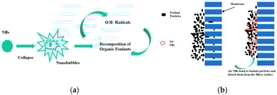
Figure 12.
Mechanism of air nanobubble cleaning ceramic membranes. Note: (a) Potential active oxygen species (ROS) generated on nanobubble and their cleaning effects; (b) Effects of nanobubbles on ceramic membrane cleaning [69].
Micro-nano bubble technology demonstrates significant potential for contaminant treatment, effectively improving wastewater quality and degrading recalcitrant organic pollutants through hydroxyl radical generation without chemical additives. It also enhances microbial activity and dissolved oxygen concentrations, enabling efficient groundwater remediation. However, practical applications face persistent challenges: current implementations primarily utilize hydraulic means for bubble generation—an energy-intensive process producing turbulent hydrodynamic conditions that impede sludge flocculation. Furthermore, sludge adhesion to bubble surfaces results in poor settleability and significant flotation issues.
4.2. Mineral Flotation
Leveraging the characteristics of micro-nano bubbles, including their large specific surface area, strong adsorption capacity, and high stability, this technology has become a crucial means of improving the recovery efficiency of fine minerals in mineral flotation. By reducing bubble size, it significantly enhances the particle–bubble collision probability [70,71]; the process is schematically demonstrated in Figure 13.
The collision between particles and bubbles is determined by their respective sizes and the hydrodynamic conditions within the flotation cell, as described by the formula derived by Yoon and Luttrell (9) [72]:

Figure 13.
Principle of improved flotation performance by nanobubbles [73].
Figure 13.
Principle of improved flotation performance by nanobubbles [73].

In the formula, Pc represents the collision probability; Re denotes the Reynolds number; Rp and Rb correspond to the particle and bubble sizes.
The core mechanism lies in the ability of MNBs to enhance particle adhesion and accelerate the rupture of wetting films, thereby improving flotation efficiency. Industrial applications have demonstrated that, compared to conventional flotation, nanobubble technology can increase mineral recovery by approximately 23% [73,74], Moreover, it exhibits energy-efficient and high-performance advantages in the separation of fine-grained minerals such as coal and graphite. The development of key equipment, such as the cyclonic-static microbubble flotation column, has further promoted the widespread adoption of this technology in mineral processing [75].
Currently, the generation methods of micro-nano bubbles and their applications in mineral flotation remain a key research focus. Hydrodynamic cavitation serves as a prevalent technique for micro-nano bubble production. These studies not only provide foundational research directions for micro-nano bubble flotation technology but also identify critical knowledge gaps within the field, thereby offering novel perspectives for future investigations.
4.3. Medical Field
Micro-nano bubbles demonstrate multidimensional application value in the medical field due to their high solubility, strong permeability, and excellent biocompatibility; the process is schematically demonstrated in Figure 14. Their core functionalities are manifested in three key aspects: targeted drug delivery, medical imaging enhancement, and precision therapy [76,77,78]. For instance, Prajapati [79] systematically investigated the biomedical applications of MNBs and demonstrated their efficacy as ultrasound contrast agents, enabling clinicians to visualize organs and tissues with improved resolution. Through surface modification with targeting ligands, MNBs can achieve specific delivery of drugs/genes while also exhibiting potential in promoting tissue repair and improving hypoxic microenvironments.
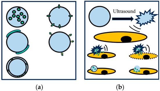
Figure 14.
(a) Integration of drug molecules; (b) Drug delivery [80].
In summary, micro-nano bubble technology demonstrates substantial application prospects in the medical field, including drug delivery, medical imaging, and therapeutic applications. Currently, researchers are investigating the interactions between micro-nano bubbles and biological systems, while exploring their utility in novel therapeutic domains such as immunotherapy and gene therapy. Concurrently, rigorous evaluation of the technique’s safety and reliability is being conducted.
4.4. Crop Yield Enhancement
MNBs technology significantly increases soil oxygen content through its high specific surface area and strong permeability, improves soil structure, and promotes root respiration and nutrient absorption. The shock force generated by its rupture can stimulate plant cell expansion, enhance photosynthesis, and carry microorganisms to assist nutrient transport, comprehensively improving crop growth efficiency. Liu [81] used nanobubble oxygenation to increase the yield of greenhouse crops. Rameshkumar [49] used nanobubbles prepared by electrolysis (264–293 nm) to simultaneously shorten the seed germination cycle and increase growth speed by three times; Minamikawa [82] used oxygen nanobubble irrigation in paddy fields to optimize soil porosity and aerobic conditions, promoting root growth and increasing crop yield; Liu [83] found that nanobubble water increased barley germination rate by 15–25%.
Micro-nano bubble technology has demonstrated efficacy in enhancing crop yield by improving soil oxygen availability and promoting nutrient uptake through plant root systems. However, the long-term impacts on crop growth dynamics and its applicability across diverse crop species and soil conditions require further investigation.
4.5. Enhanced Oil Recovery
In gas flooding, CO2-enhanced oil recovery (EOR) technology has garnered significant attention due to its dual benefits of improving crude oil properties and enabling carbon sequestration [84,85]. However, its large-scale application is constrained by challenges such as gas source availability, gas channeling, and corrosion issues. To address these limitations, researchers have proposed micro-nano bubble-assisted CO2 flooding technology. By leveraging the high specific surface area and superior mobility of MNBs, this approach enables CO2 to penetrate deep into reservoir pores, effectively reducing crude oil viscosity while enhancing sweep efficiency and sequestration safety [86,87,88]; the process is schematically demonstrated in Figure 15 and Figure 16.
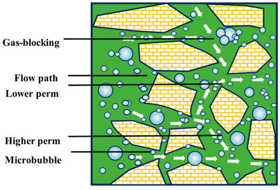
Figure 15.
Gas flooding capability of micro-nano bubbles [89].
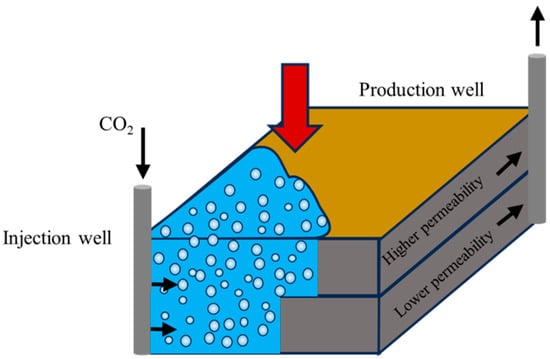
Figure 16.
Gas-blocking capacity of CO2 microbubbles [90].
In 2010, Xue first proposed a chemical-free CO2 microbubble technology. Experimental results demonstrated that this technology could increase CO2 solubility by over 20% and significantly improve pore utilization and sweep efficiency in low-permeability reservoirs [91,92,93,94,95]. Russian scholar Savitski [96] achieved a 26% incremental oil recovery using microbubble technology in the Samotlor oilfield. Meanwhile, Akai et al. [95] found that micro-nano bubbles could delay CO2 breakthrough time and enhance oil recovery by 3%. Since 2008, the China National Petroleum Corporation research team has applied ion-matching micro-nano bubbles technology in the Wuliwan oilfield (Changqing) to improve recovery rates, with an estimated 10% increase. Additionally, in 2024, Shi X.Y. et al. [97] demonstrated that microbubble-enhanced binary composite flooding could boost heavy oil recovery by up to 12%.
The core advantages of this technology lie in the synergistic effects of the Jamin effect, enhanced pore utilization efficiency, and improved stability, demonstrating particularly remarkable efficacy in low-permeability and heavy oil reservoirs. However, critical technical challenges remain to be addressed, including the stability of microbubbles under high-temperature and high-pressure conditions, reservoir geological compatibility, and the optimization of large-scale injection parameters.
5. Conclusions and Future Perspectives
Micro-nano bubbles possess unique physicochemical properties that distinguish them from ordinary bubbles, endowing them with broad application prospects in environmental protection, medicine, agriculture, and enhanced oil recovery. With the advancement of science and technology, the methods for generating micro-nano bubbles have also developed rapidly.
This review establishes a more systematic and refined taxonomy of micro-nano bubble generation methods, providing in-depth mechanistic analysis of parameter optimization and performance enhancement strategies. We place particular emphasis on incorporating emerging innovative generation techniques and optimization approaches reported in recent years, explicitly identifying method hybridization as a critical development pathway. Regarding applications, beyond comprehensive coverage of traditional implementation fields, we highlight significant advances in oil recovery enhancement-reflecting cutting-edge industrial practices. Nevertheless, current research confronts three persisting challenges: insufficient quantification of bubble dynamics, prohibitive scaling costs, and unresolved multiscale interaction mechanisms, which necessitate coordinated fundamental and engineering breakthroughs. However, current research still faces challenges including the difficulty in quantitatively characterizing bubble dynamics, high costs of large-scale preparation, and unclear cross-scale mechanisms. These challenges require breakthroughs in both fundamental theory and engineering practice.
In the future, research on micro-nano bubbles technology should focus on in-depth exploration of generation mechanisms, development of new materials, and expansion of application fields. In terms of technological improvement, enhancing bubble stability, reducing energy consumption, and optimizing device design will be key directions. Additionally, micro-nano bubbles technology also has broad application prospects in emerging fields such as intelligent manufacturing and new energy. It will play an important role in achieving sustainable development goals, improving the quality of social life, and enhancing the ecological environment.
Author Contributions
Writing—original draft, writing—review and editing, conceptualization, S.Z.; conceptualization, J.W.; supervision, Y.L. All authors have read and agreed to the published version of the manuscript.
Funding
This article was funded by the PetroChina Company Limited projects, including New Mechanism and New Method Research of Great Oil Recovery in Low Permeability/Tight Reservoir (2023ZZ0404).
Data Availability Statement
No new data were created or analyzed in this study.
Acknowledgments
The support given by The State Key Laboratory of Enhanced Oil Recovery of Open Fund Funded Project, Major Special Projects of CNPC is acknowledged.
Conflicts of Interest
Authors Jiazhong Wu and Yisong Li were employed by the State Key Laboratory of Enhanced Oil & Gas Recovery, Research Institute of Petroleum Exploration & Development. The remaining authors declare that the research was conducted in the absence of any commercial or financial relationships that could be construed as a potential conflict of interest.
References
- Agarwal, A.; Ng, W.J.; Liu, Y. Principle and Applications of Microbubble and Nanobubble Technology for Water Treatment. Chemosphere 2011, 84, 1175–1180. [Google Scholar] [CrossRef] [PubMed]
- Bowonder, B.; Kumar, R. Studies in Bubble Formation - IV: Bubble Formation at Porous Discs. Chem. Eng. Sci. 1970, 25, 25–32. [Google Scholar] [CrossRef]
- Takahashi, T.; Miyahara, T.; Mochizuki, H. Fundamental-Study of Bubble Formation in Dissolved Air-Pressure Flotation. J. Chem. Eng. Jpn. 1979, 12, 275–280. [Google Scholar] [CrossRef]
- Ketkar, D.R.; Mallikarjunan, R.; Venkatachalam, S. Electroflotation of Quartz Fines. Int. J. Miner. Process. 1991, 31, 127–138. [Google Scholar] [CrossRef]
- Ding, G.D.; Chen, J.Q.; Wang, C.S.; Chao, S. Structural Design and Numerical Simulation of Axial-Swirling Type Micro-Bubble Generator. Chin. J. Process Eng. 2018, 18, 934–941. [Google Scholar]
- Azevedo, A.; Oliveira, H.; Rubio, J. Bulk Nanobubbles in the Mineral and Environmental Areas: Updating for Research and Applications. Adv. Colloid Interface Sci. 2019, 271, 101992. [Google Scholar] [CrossRef]
- Li, H.; Hu, L.; Xia, Z. Impact of Groundwater Salinity on Bioremediation Enhanced by Micro-Nano Bubbles. Materials 2013, 6, 3676–3687. [Google Scholar] [CrossRef]
- Swart, B.; Zhao, Y.; Khaku, M.; Che, E.; Maltby, R.; Chew, Y.M.J.; Wenk, J. In Situ Characterisation of Size Distribution and Rise Velocity of Microbubbles by High-Speed Photography. Chem. Eng. Sci. 2020, 225, 115836. [Google Scholar] [CrossRef]
- Huang, B.; Wang, H.; Gu, G.H. Zeta Potential of Air Bubble. Appl. Chem. Ind. 2014, 43, 142–145. [Google Scholar]
- Ahmed, A.K.A.; Sun, C.; Hua, L.; Zhang, Z.; Zhang, Y.; Zhang, W.; Marhaba, T. Generation of Nanobubbles by Ceramic Membrane Filters: The Dependence of Bubble Size and Zeta Potential on Surface Coating, Pore Size and Injected Gas Pressure. Chemosphere 2018, 203, 327–335. [Google Scholar] [CrossRef]
- Kim, M.-S.; Kwak, D.-H. Effect of Zeta Potential on Collision-Attachment Coefficient and Removal Efficiency for Dissolved Carbon Dioxide Flotation. Environ. Eng. Sci. 2017, 34, 272–280. [Google Scholar] [CrossRef]
- Jia, W.; Ren, S.; Hu, B. Effect of Water Chemistry on Zeta Potential of Air Bubbles. Int. J. Electrochem. Sci. 2013, 8, 5828–5837. [Google Scholar] [CrossRef]
- Smoluchowski, M.V. Drei Vortrage Uber Diffusion, Brownsche Molekularbewegung Und Koagulation von Kolloidteilchen. Z. Physik. 1916, 17, 585–599. [Google Scholar]
- Takahashi, M. ξ Potential of Microbubbles in Aqueous Solutions: Electrical Properties of the Gas-Water Interface. J. Phys. Chem. B 2005, 109, 21858–21864. [Google Scholar] [CrossRef] [PubMed]
- Hewage, S.A.; Kewalramani, J.; Meegoda, J.N. Stability of Nanobubbles in Different Salts Solutions. Colloids Surf. A-Physicochem. Eng. Asp. 2021, 609, 125669. [Google Scholar] [CrossRef]
- Matsumoto, M.; Tanaka, K. Nano Bubble-Size Dependence of Surface Tension and inside Pressure. Fluid Dyn. Res. 2008, 40, 546–553. [Google Scholar] [CrossRef]
- Nock, W.J.; Heaven, S.; Banks, C.J. Mass Transfer and Gas-Liquid Interface Properties of Single CO2 Bubbles Rising in Tap Water. Chem. Eng. Sci. 2016, 140, 171–178. [Google Scholar] [CrossRef]
- Bao, Y.; Jia, J.; Tong, S. A Review on Single Bubble Gas-Liquid Mass Transfer. Chin. J. Chem. Eng. 2020, 28, 2707–2722. [Google Scholar] [CrossRef]
- Parkinson, L.; Sedev, R.; Fornasiero, D.; Ralston, J. The Terminal Rise Velocity of 10–100 Microm Diameter Bubbles in Water. J Colloid Interface Sci 2008, 322, 168–172. [Google Scholar] [CrossRef]
- Yang, C.; Dabros, T.; Li, D.; Czarnecki, J.; Masliyah, J.H. Measurement of the Zeta Potential of Gas Bubbles in Aqueous Solutions by Microelectrophoresis Method. J. Colloid Interface Sci. 2001, 243, 128–135. [Google Scholar] [CrossRef]
- Sebba, F. An Improved Generator for Micron-Sized Bubbles. Chem. Ind. 1985, 91–92. [Google Scholar]
- Zhang, W.; Li, Z.H.; Agblevor, F.A. Microbubble Fermentation of Recombinant Pichia pastoris for Human Serum Albumin Production. Process Biochem. 2005, 40, 2073–2078. [Google Scholar] [CrossRef]
- Xu, Q.; Nakajima, M.; Ichikawa, S. A Comparative Study of Microbubble Generation by Mechanical Agitation and Sonication. Innov. Food Sci. Emerg. Technol. 2008, 9, 489–494. [Google Scholar] [CrossRef]
- Etchepare, R.; Oliveira, H.; Azevedo, A. Nanobubbles: Generation Using a Multiphase Pump, Properties and Features in Flotation. Miner. Eng. 2017, 112, 19–26. [Google Scholar] [CrossRef]
- Shi, Y.L.; Wang, S.F.; Wu, G.; Chen, X. Study on the Mechanism of the Micro-Bubble Formation of Pressure Dissolved Air Flotation and Application. Ind. Water Treat. 2012, 32, 20–23. [Google Scholar]
- Azevedo, A.; Etchepare, R.; Calgaroto, S.; Rubio, J. Aqueous Dispersions of Nanobubbles: Generation, Properties and Features. Miner. Eng. 2016, 94, 29–37. [Google Scholar] [CrossRef]
- Zhai, L.; Cui, Y.; Li, C.; Shi, X.; Gao, J.; Lan, X. Research and Application Process of Microbubble Generator. Chem. Ind. Eng. Prog. 2024, 43, 111–123. [Google Scholar]
- Li, J.; Song, Y.; Yin, J.; Wang, D. Investigation on the Effect of Geometrical Parameters on the Performance of a Venturi Type Bubble Generator. Nucl. Eng. Des. 2017, 325, 90–96. [Google Scholar] [CrossRef]
- Wang, X.; Shuai, Y.; Zhou, X.; Huang, Z.; Yang, Y.; Sun, J.; Zhang, H.; Wang, J.; Yang, Y. Performance Comparison of Swirl-Venturi Bubble Generator and Conventional Venturi Bubble Generator. Chem. Eng. Process. 2020, 154, 108022. [Google Scholar] [CrossRef]
- Li, X. Research on the Characteristics of a New Microbubble Generator Based on the Venturi Tube. Chem. Eng. Process. 2024, 31, 109876. [Google Scholar] [CrossRef]
- Levitsky, I.; Tavor, D.; Gitis, V. Generation of Two-Phase Air-Water Flow with Fine Microbubbles. Chem. Eng. Technol. 2016, 39, 1537–1544. [Google Scholar] [CrossRef]
- Xu, X.; Ge, X.; Qian, Y. Effect of Nozzle Diameter on Bubble Generation with Gas Self-Suction through Swirling Flow. Chem. Eng. Res. Des. 2018, 138, 13–20. [Google Scholar] [CrossRef]
- Kim, S.; Kim, H.; Han, M.; Kim, T. Generation of Sub-Micron (Nano) Bubbles and Characterization of Their Fundamental Properties. Environ. Eng. Res. 2018, 24, 382–388. [Google Scholar] [CrossRef]
- Wu, Y.; Chen, H.; Song, X. Experimental and Numerical Study on the Bubble Dynamics and Flow Field of a Swirl Flow Microbubble Generator with Baffle Internals. Chem. Eng. Sci. 2022, 263, 118066. [Google Scholar] [CrossRef]
- Wu, M.; Song, H.; Liang, X.; Huang, N.; Li, X. Generation of Micro-Nano Bubbles by Self-Developed Swirl-Type Micro-Nano Bubble Generator. Chem. Eng. Process. 2022, 181, 109136. [Google Scholar] [CrossRef]
- Li, Z.K.; Zhang, Z.H.; Guo, S. Research on the Jet Bubble Generator for Microbubble Flotation. Min. Res. Dev. 2007, 5, 54–56. [Google Scholar] [CrossRef]
- Hui, H.L.; Qiu, X.Q.; Zhang, J.W.; Zhao, Z.B. Experimental Study on Optimization of Throat-Nozzle Distance for Jet Bubble Generator. Energy Conserv. 2011, 30, 5. [Google Scholar] [CrossRef]
- Hu, X.; Zhang, B.; Wu, C.; Xu, X.; Xue, M.; Zheng, X. Numerical Simulation and Structural Optimization of Swirl Flow Micro-Nano Bubble Generator. Coatings 2023, 13, 1468. [Google Scholar] [CrossRef]
- Tian, H.; Pi, S.; Feng, Y.; Zhou, Z.; Zhang, F.; Zhang, Z. One-Dimensional Drift-Flux Model of Gas Holdup in Fine-Bubble Jet Reactor. Chem. Eng. J. 2020, 386, 121222. [Google Scholar] [CrossRef]
- Li, X.; Su, W.; Liu, Y.; Yan, X.; Wang, L.; Zhang, H. Comparison of Bubble Velocity, Size, and Holdup Distribution between Single- and Double-Air Inlet in Jet Microbubble Generator. Asia-Pac. J. Chem. Eng. 2021, 16, e2611. [Google Scholar] [CrossRef]
- Yasui, K. Acoustic Cavitation and Bubble Dynamics; Springer Briefs in Molecular Science; Springer International Publishing: Cham, Switzerland, 2018; ISBN 978-3-319-68236-5. [Google Scholar]
- Ma, Y.L.; Shen, S.L.; Chen, J.L.; Xu, Y.L. Ultrasonic Assisted Removal of Micro-Bubbles in Water. Chem. Ind. Eng. 2024, 41, 131–137. [Google Scholar]
- Makuta, T.; Suzuki, R.; Nakao, T. Generation of Microbubbles from Hollow Cylindrical Ultrasonic Horn. Ultrasonics 2013, 53, 196–202. [Google Scholar] [CrossRef] [PubMed]
- Liu, Y.N.; Chen, W.Z.; Huang, W. High-Precision Measurement Techniques for Stable Acoustic Cavitation Bubbles. Chin. Sci. Bull. 2005, 50, 2458–2462. [Google Scholar] [CrossRef]
- Mo, C.R. Study on the Generation Method and Properties of Nanobubbles Based on Ultrasonic Cavitation. Master’s Thesis, University of Chinese Academy of Sciences, Beijing, China, 2019. [Google Scholar]
- Chandran, P.; Bakshi, S.; Chatterjee, D. Study on the Characteristics of Hydrogen Bubble Formation and Its Transport during Electrolysis of Water. Chem. Eng. Sci. 2015, 138, 99–109. [Google Scholar] [CrossRef]
- Sakai, O.; Kimura, M.; Shirafuji, T.; Tachibana, K. Underwater Microdischarge in Arranged Microbubbles Produced by Electrolysis in Electrolyte Solution Using Fabric-Type Electrode. Appl. Phys. Lett. 2008, 93, 231501. [Google Scholar] [CrossRef]
- Liu, J.L. Research on Micro-Nano Bubbles Generation Device. Master’s Thesis, Zhejiang University, Hangzhou, China, 2012. [Google Scholar]
- Rameshkumar, C.; Lakshmi Sankar, S.; Senthilkumar, G. Characterisation of Seed Germination Using Nanaobubbled Water. Int. J. Ambient Energy 2019, 43, 745–748. [Google Scholar] [CrossRef]
- Liu, M.; Guo, X.-F.; Wang, J.-M.; Jiang, L. Behavior of Bubbles on Electrodes with Hierarchical Microporous Structures and Different Wettability. Acta Phys.-Chim. Sin. 2012, 28, 2931–2938. [Google Scholar] [CrossRef]
- Xu, T.D.; Pang, M.J.; Fei, T. Experimental Study on Microbubble Generation by Electrolysis Method. Lab. Sci. 2015, 18, 5. [Google Scholar]
- Tanaka, Y.; Kikuchi, K.; Saihara, Y.; Ogumi, Z. Bubble Visualization and Electrolyte Dependency of Dissolving Hy-drogen in Electrolyzed Water Using Solid-Polymer-Electrolyte. Electrochim. Acta 2005, 50, 5229–5236. [Google Scholar] [CrossRef]
- Kukizaki, M.; Goto, M. Size Control of Nanobubbles Generated from Shirasu-Porous-Glass (SPG) Membranes. J. Membr. Sci. 2006, 281, 386–396. [Google Scholar] [CrossRef]
- Wu, S.J.; Fang, W.M.; Zhao, H.W.; Chang, C. Research on Microbubbles Formation by High-Speed Cross-Flow. Technol. Water Treat. 2009, 35, 44–48. [Google Scholar]
- Khirani, S.; Kunwapanitchakul, P.; Augier, F.; Guigui, C.; Guiraud, P.; Hebrard, G. Microbubble Generation through Porous Membrane under Aqueous or Organic Liquid Shear Flow. Ind. Eng. Chem. Res. 2012, 51, 1997–2009. [Google Scholar] [CrossRef]
- Zheng, C.; Tan, J.; Wang, K.; Luo, G.S. Stability and Pressure Drop of Gas-Liquid Micro-Dispersion Flows through a Capillary. Chem. Eng. Sci. 2016, 140, 134–143. [Google Scholar] [CrossRef]
- Xu, Z.H.; Zhao, H.W.; Fang, W.M.; Zhong, B.H. Research on Microbubbles Generation by Metal Microporous Tube. Tech. Equip. Environ. Pollut. Control 2006, 7, 78–82. [Google Scholar]
- Fujikawa, S.; Zhang, R.S.; Hayama, S.; Peng, G.Y. The Control of Micro-Air-Bubble Generation by a Rotational Porous Plate. Int. J. Multiph. Flow 2003, 29, 1221–1236. [Google Scholar] [CrossRef]
- Sadatomi, M.; Kawahara, A.; Matsuura, H.; Shikatani, S. Micro-Bubble Generation Rate and Bubble Dissolution Rate into Water by a Simple Multi-Fluid Mixer with Orifice and Porous Tube. Exp. Therm. Fluid Sci. 2012, 41, 23–30. [Google Scholar] [CrossRef]
- Juwana, W.E.; Widyatama, A.; Dinaryanto, O.; Budhijanto, W.; Indarto; Deendarlianto. Hydrodynamic Characteristics of the Microbubble Dissolution in Liquid Using Orifice Type Microbubble Generator. Chem. Eng. Res. Des. 2019, 141, 436–448. [Google Scholar] [CrossRef]
- Xie, B.Q.; Zhou, C.J.; Sang, L.; Ma, X.D.; Zhang, J.S. Preparation and Characterization of Microbubbles with a Porous Ceramic Membrane. Chem. Eng. Process. 2021, 159, 108213. [Google Scholar] [CrossRef]
- Sun, L.; Fan, M.; Xu, B.; Yu, H.; Wang, Y.; Zhang, Y.; Li, P. Growth Characteristic of Microbubble in a T-Junction Microchannel in Microfluidic Chip. IOP Conf. Ser. Earth Environ. Sci. 2019, 267, 042146. [Google Scholar] [CrossRef]
- Lee, M.; Lee, E.; Lee, D.; Park, B. Stabilization and Fabrication of Microbubbles: Applications for Medical Purposes and Functional Materials. Soft Matter 2015, 11, 2067–2079. [Google Scholar] [CrossRef]
- Lin, H.; Chen, J.; Chen, C. A Novel Technology: Microfluidic Devices for Microbubble Ultrasound Contrast Agent Generation. Med. Biol. Eng. Comput. 2016, 54, 1317–1330. [Google Scholar] [CrossRef] [PubMed]
- van Hoeve, W.; Dollet, B.; Gordillo, J.M.; Versluis, M.; van Wijngaarden, L.; Lohse, D. Bubble Size Prediction in Co-Flowing Streams. EPL 2011, 94, 64001. [Google Scholar] [CrossRef][Green Version]
- Mehrabi, M.; Isfahani, A.H.M. A New Micro Pump for Rapid and Accurate Microscale Droplet Manipulation Using Thermo-Viscous Actuation. Sci. Iran. 2022, 29, 2279–2289. [Google Scholar] [CrossRef]
- Jenkins, K.; Michelsen, D.; Novak, J. Application of Oxygen Microbubbles for In-Situ Biodegradation of P-Xylene-Contaminated Groundwater in a Soil Column. Biotechnol. Prog. 1993, 9, 394–400. [Google Scholar] [CrossRef]
- Dacheng, B. Water Purification in Wide Enclosed Water Areas Using Microbubble Generation Technology. Multiph. Flow 1997, 11, 263–266. [Google Scholar] [CrossRef][Green Version]
- Ghadimkhani, A.; Zhang, W.; Marhaba, T. Ceramic Membrane Defouling (Cleaning) by Air Nano Bubbles. Chemosphere 2016, 146, 379–384. [Google Scholar] [CrossRef]
- Li, C.; Zhang, H. Surface Nanobubbles and Their Roles in Flotation of Fine Particles-A Review. J. Ind. Eng. Chem. 2022, 106, 37–51. [Google Scholar] [CrossRef]
- Li, C.; Zhang, H. A Review of Bulk Nanobubbles and Their Roles in Flotation of Fine Particles. Powder Technol. 2022, 395, 618–633. [Google Scholar] [CrossRef]
- Yoon, R.H.; Luttrell, G.H. The Effect of Bubble Size on Fine Particle Flotation. Miner. Process. Extr. Metall. Rev. 1989, 5, 101–122. [Google Scholar] [CrossRef]
- Rosa, A.F.; Rubio, J. On the Role of Nanobubbles in Particle-Bubble Adhesion for the Flotation of Quartz and Apatitic Minerals. Miner. Eng. 2018, 127, 178–184. [Google Scholar] [CrossRef]
- Calgaroto, S.; Azevedo, A.; Rubio, J. Flotation of Quartz Particles Assisted by Nanobubbles. Int. J. Miner. Process. 2015, 137, 64–70. [Google Scholar] [CrossRef]
- Zhang, H.-F.; Chen, L.; Santosh, M.; Menzies, M.A. Construction and Destruction of Cratons: Preface. Gondwana Res. 2013, 23, 1–3. [Google Scholar] [CrossRef]
- Liu, Y.; Miyoshi, H.; Nakamura, M. Encapsulated Ultrasound Microbubbles: Therapeutic Application in Drug/Gene Delivery. J. Control. Release 2006, 114, 89–99. [Google Scholar] [CrossRef] [PubMed]
- Vilela, D.; Cossio, U.; Parmar, J.; Martinez-Villacorta, A.M.; Gomez-Vallejo, V.; Llop, J.; Sanchez, S. Medical Imaging for the Tracking of Micromotors. ACS Nano 2018, 12, 1220–1227. [Google Scholar] [CrossRef]
- Tamagawa, M.; Yamanoi, I.; Ishimatsu, N.; Suetsugu, S. Prototype of Microcapsule for Shock Wave Drug Delivery Systems and Analysis of Deformation Process of a Bubble in a Capsule Model; Kim, S., Suh, T., Eds.; Springer: Berlin/Heidelberg, Germany, 2007; Volume 14, pp. 3236–3237. [Google Scholar]
- Prajapati, J.V.; Agrawal, Y.K. Synthesis, Characterization and Application of Microbubbles: A Review. Int. J. Pharm. L Sci. Res. 2012, 3, 1532–1543. [Google Scholar] [CrossRef]
- Harvey, C.J.; Blomley, M.J.K.; Eckersley, R.J.; Cosgrove, D.O. Developments in Ultrasound Contrast Media. Eur. Radiol. 2001, 11, 675–689. [Google Scholar] [CrossRef]
- Liu, Y.; Zhou, Y.; Wang, T.; Pan, J.; Zhou, B.; Muhammad, T.; Zhou, C.; Li, Y. Micro-Nano Bubble Water Oxygation: Synergistically Improving Irrigation Water Use Efficiency, Crop Yield and Quality. J. Clean Prod. 2019, 222, 835–843. [Google Scholar] [CrossRef]
- Minamikawa, K.; Makino, T. Oxidation of Flooded Paddy Soil through Irrigation with Water Containing Bulk Oxygen Nanobubbles. Sci. Total Environ. 2020, 709, 136323. [Google Scholar] [CrossRef]
- Liu, S.; Kawagoe, Y.; Makino, Y.; Oshita, S. Effects of Nanobubbles on the Physicochemical Properties of Water: The Basis for Peculiar Properties of Water Containing Nanobubbles. Chem. Eng. Sci. 2013, 93, 250–256. [Google Scholar] [CrossRef]
- Wang, P. Research Status of CO2 Enhanced Oil Recovery Technology. China Chem. Trade 2014, 32. [Google Scholar] [CrossRef]
- Hao, M.; Song, Y.C. Research Status of CO2 Enhanced Oil Recovery Technology. Drill. Prod. Technol. 2010, 33, 59–63. [Google Scholar] [CrossRef]
- Microbubble Technology Boosts Enhanced Oil Recovery. Petrochem. Ind. Appl. 2018, 37, 147–148.
- Jiang, L.; Xue, Z.; Park, H. Enhancement of CO2 Dissolution and Sweep Efficiency in Saline Aquifer by Micro Bubble CO2 Injection. Int. J. Heat Mass Transf. 2019, 138, 1211–1221. [Google Scholar] [CrossRef]
- Patmonoaji, A.; Zhang, Y.; Xue, Z.; Park, H.; Suekane, T. Experimental and Numerical Simulation of Supercritical CO2 Microbubble Injection into a Brine-Saturated Porous Medium. Int. J. Greenh. Gas Control 2019, 91, 102830. [Google Scholar] [CrossRef]
- Le, N.N.H.; Sugai, Y.; Vo-Thanh, H. Experimental Investigation on Plugging Performance of CO2 Microbubbles in Porous Media. J. Pet. Sci. Eng. 2022, 211, 110187. [Google Scholar] [CrossRef]
- Adamova, T.P.; Skiba, S.S.; Manakov, A.Y.; Kutateladze, S.Y.M. Growth Rate of CO2 Hydrate Film on Water-Oil and Water-Gaseous CO2 Interface. Chin. J. Chem. Eng. 2023, 56, 266–272. [Google Scholar] [CrossRef]
- Microbubble Carbon Dioxide Injection for Enhanced Dissolution in Geological Sequestration and Improved Oil Recovery. Energy Procedia 2014, 63, 7939–7946. [CrossRef]
- Xue, Z.; Park, H.; Ueda, R.; Nakano, M.; Nishii, T.; Inagaki, S. Microbubble CO2 Injection for Enhanced Oil Recovery and Geological Sequestration in Heterogeneous and Low Permeability Reservoirs. In Proceedings of the 14th International Conference on Greenhouse Gas Control Technologies, GHGT-14, Melbourne, Australia, 21–25 October 2018. [Google Scholar]
- Xue, Z.; Tsuji, S.; Kameyama, H. Development of Carbon Dioxide Microbubble Sequestration into Saline Aquifer and CO2-EOR Reservoirs. Energy Procedia 2013, 37, 4628–4634. [Google Scholar] [CrossRef]
- Xue, Z.; Yamada, T.; Matsuoka, T.; Kameyama, H.; Nishio, S. Carbon Dioxide Microbubble Injection–Enhanced Dissolution in Geological Sequestration. Energy Procedia 2011, 4, 4307–4313. [Google Scholar] [CrossRef]
- Akai, T.; Xue, Z.; Yamashita, Y.; Yoshizawa, M. Application of CO2 Micro Bubble for the Innovative CO2-EOR. In Proceedings of the Abu Dhabi International Petroleum Exhibition and Conference, Abu Dhabi, United Arab Emirates, 10 November 2015; SPE: Richardson, TX, USA, 2015; p. D021S034R002. [Google Scholar]
- Savitski, N.V.V. Findings of Experimental and Field Research into Oil Displacement by Means of Finely Dispersed Water-Gas Mixtured (FDWGM). In Proceedings of the SPE Russian Petroleum Technology Conference, Moscow, Russia, 25–29 October 2020; SPE: Richardson, TX, USA, 2010; p. SPE-138067-MS. [Google Scholar]
- Shi, X.Y.; Kuai, J.W.; Wang, G.H.; Ding, M.C. Laboratory Experiment on Enhancing Conventional Heavy Oil Recovery by Microbubble-Enhanced S/P Binary Flooding. China Offshore Oil Gas 2024, 36, 84–90. [Google Scholar]


Disclaimer/Publisher’s Note: The statements, opinions and data contained in all publications are solely those of the individual author(s) and contributor(s) and not of MDPI and/or the editor(s). MDPI and/or the editor(s) disclaim responsibility for any injury to people or property resulting from any ideas, methods, instructions or products referred to in the content. |
© 2025 by the authors. Licensee MDPI, Basel, Switzerland. This article is an open access article distributed under the terms and conditions of the Creative Commons Attribution (CC BY) license (https://creativecommons.org/licenses/by/4.0/).