Article

A Numerical Model for Inelastic Buckling in Cold Upset Forging: Stress Analysis and Optimal Billet Geometry

1
Department of Industrial Engineering, Operations Management, and Mechanical Engineering, Vaal University of Technology, Private Bag X021, Andries Potgeiter Blvd, Vanderbijlpark 1911, South Africa
2
Department of Chemical Engineering, Durban University of Technology (DUT), Steve Biko Campus, Durban 4000, South Africa
*
Author to whom correspondence should be addressed.
Processes 2025, 13(7), 2078; https://doi.org/10.3390/pr13072078
Submission received: 5 March 2025 / Revised: 30 April 2025 / Accepted: 21 May 2025 / Published: 1 July 2025

Abstract

The forging industry has increasingly emphasised quality and reproducibility, making computer simulations essential for predicting and improving the process. A major challenge in cold upset forging is billet buckling, which leads to defective products. Existing numerical models, such as the Euler and Rankine-Gordon formulas, mainly focus on elastic buckling. This study aimed to develop a numerical model that defined inelastic buckling during forging, particularly in cold upset forging, which could be used to determine the buckled billets and their stresses, identify the deflection point for different billet geometries, and specify the optimum billet geometry for aluminium. A numerical approach was used to model the forging operation and obtain simulation data for stress variation against die strokes. Seven billet geometries (10–40 mm in diameter, each with a length of 120 mm) and three frictional conditions (µ = 0.12, 0.16, and 0.35) were applied. The simulation results showed that the billet geometry and the strain hardening exponent had a crucial impact on the buckling behaviour, while friction seemed to alter the overall billet stresses. Rigorous non-linear regression and iterations showed that the numerical model successfully estimated the buckling stresses but failed to identify the buckling points through stress differences.

1. Introduction

Forging is a metal production process that uses compression to plastically deform a starting workpiece to the desired shape or fit for a particular application [1]. The compression occurs between a stationary lower anvil/die and a movable upper hammer or press, which imparts the required features to the job during the process [2]. By working the material, its properties, such as strength, toughness, resistance to impact and fatigue, and higher strength-to-weight ratio get enhanced so that the component can function without fail [3]. Advances in buckling analysis have expanded our understanding of geometric and material effects on deformation stability, which critically informs forging process design [4,5]. Forging processes occur in three stages: (1) the preparation of the starting stock (billets, ingots, blooms, or bars); (2) plastic deformation into a near-net shape; and (3) post-forging validation and finishing, including mandatory Non-Destructive Testing (NDT) for quality assurance, along with heat treatment, trimming, and surface finishing [1,6,7]. This classification aligns with industry standards (ASTM E1316-25) where NDT serves as a critical quality verification step rather than a secondary manufacturing operation [8,9].
Forging is one of the oldest production techniques known to humanity. It began in Mesopotamia, dating back to 4000 before Christ (BC) and earlier [10]. Popularity and interest in forging grew once people discovered the use of fire in shaping metals. Bronze and iron were some of the first metals used in the forging process to craft hand tools, armour, jewellery, and weapons of war, with rocks being used as the forge hammer, which continued to be the primary method of forging metal until open die forging for wrought iron became popular in the early 19th century [10,11,12].
Modern forging research has significantly advanced beyond these historical foundations, particularly in predicting and preventing defects like buckling. Fouda et al. [13] through their work demonstrated the effectiveness of finite element methods in analysing buckling behaviour, while Magnucki and Stasiewicz [14] established fundamental relationships between porosity and structural stability that inform current practices. In the 19th century, the invention of the steam engine paved the way for advancements in modern forge engineering. As a result, powerful steam hammers and air hammers were developed, enabling larger products to be forged. This discarded the need for human labour that had restricted the size of forged items [10,11,12,15]. Moreover, this allowed the forging industry to expand and limit its reliance on harnessing the flow of rivers to generate power for the forge hammers, a method that was used during the 15th century [11,16]. As the forging practice continued, towards the late 19th and the early 20th century smiths began incorporating hammers driven by transmission shafts to produce an array of parts mainly for the railway, car, and agricultural industries [17,18].
Technology in forging was further developed in the second half of the 20th century due to the increased use of solid-state electrical induction heaters, which improved the throughput and dimensional control of the forged products [19,20]. These technological advancements concur with the critical theoretical developments in plasticity and buckling analysis by Ha et al. [21] on billet geometry optimization and Dokšanović et al.’s [22] studies on aluminium alloy stability under compression. Ironically, the context of wartime (namely, World War I and World War II) greatly impacted the forging industry due to the increased demand to produce weapons. This necessitated the enhancement of forge press equipment, forging processes, and forging machines in an effort to meet the high demand for quality war arsenal [15].
The art of forging has evolved immensely from the days of blacksmiths simply using fire, a hammer, and an anvil to craft items from metals. In the modern world, automation through computer-controlled machinery and robotics has made the process more sophisticated yet efficient and faster in producing forged products in a variety of materials, shapes, sizes, and finishes. Current research frontiers focus on integrating advanced simulation techniques with practical process control, as demonstrated by Zhao et al.’s [23] work on aerospace titanium alloys and Gong et al.’s [24] on residual stresses in aluminium forgings. Even so, research is continuously carried out to develop a more innovative method of forging that is more efficient, faster, and cost-effective [19,23,25].
The impact that forging has had and continues to have in the engineering field is substantial since several mechanical components such as gears, levers, sprockets, wheel hubs, axle beams, shafts, rollers, etc. used in various machinery are manufactured through this process [26]. This results from the advantages this procedure has offered, such as that parts manufactured are more vigorous, offer high ductility, require fewer secondary operations, which translates to fewer production costs, and excellent design flexibility is achievable. The structure of the workpiece metal gets refined through forging, which offers more consistent and better metallurgical properties and minimal material wastage.
This study thus aimed to develop a numerical model that defined inelastic buckling during forging, particularly in cold upset forging, which could be used to determine the buckled billets and their stresses, identify the deflection point for different billet geometries, and specify the optimum billet geometry for aluminium. Building upon recent work in porous materials and beam buckling analysis, our approach uniquely combines numerical simulation with practical design guidelines to address a critical gap in cold forging process optimization.

2. Materials and Methods

2.1. Material

Pure aluminium was selected for cold forging. Two core material characteristics were defined: elasticity and plasticity. Elastic properties were specified using Young’s modulus and Poisson’s ratio, while plasticity was modelled using the power hardening rule, incorporating compressive yield strength and the strain hardening exponent. Material property values were sourced from the ANSYS (Ansys 2023 R2) material database, as shown in Table 1.

2.2. CAD Model Design

DS SolidWorks 2023, a CAD software (AutoCAD 2023) by Dassault Systems, was employed to generate geometries for numerical simulations. Seven cylindrical billet geometries were designed, ranging from 10 mm to 40 mm in diameter, all with a length of 120 mm. The upper and lower dies were modelled as rectangular solids (20 mm × 150 mm × 50 mm) to ensure sufficient surface area for material flow during simulation. The billet and dies were modelled as separate bodies to facilitate numerical identification. Figure 1 illustrates the upset forging setup for a 25 mm diameter billet.

2.3. Choice of Simulation Software

ANSYS was selected for finite element analysis (FEA). The ANSYS streamlined geometry importation from SolidWorks via the AP203 STEP file format and facilitated straightforward constraint and loading condition definitions.

2.4. Modelling Approach

2.4.1. Defining Geometry Behaviour

The study primarily analysed stresses in the billet during plastic deformation. The dies were set as rigid bodies in ANSYS to optimise computational efficiency, reducing CPU load and simulation run time. The following model assumptions were applied: the billet is perfectly straight, the cross-section remains constant throughout the material, heat generation and strain rate effects are neglected, loading is uniform and axisymmetric, and the billet and dies exhibit symmetrical geometries. These assumptions simplified the analysis while ensuring computational efficiency.

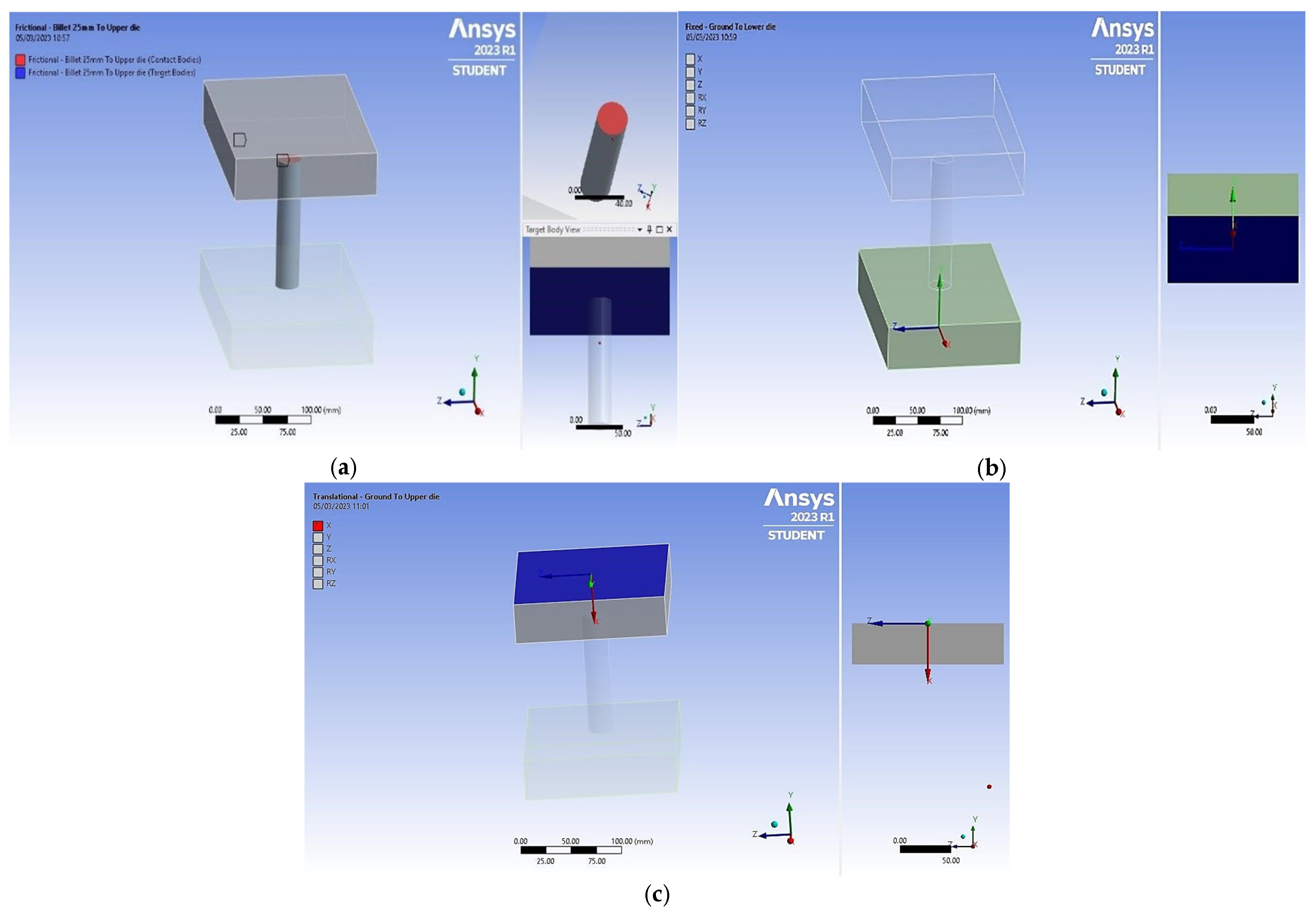
2.4.2. Connection Types

Two connection types were defined: contact regions and joints. No-separation and frictional contacts were assigned to both die–billet interfaces, ensuring sliding while maintaining contact. Friction coefficients of 0.16, 0.12, and 0.35 were used to simulate the effects of sawdust, furnace oil, and dry lubricants, respectively.
The billet faces were designated as contact bodies, while the die faces were assigned target bodies as per Table 2. Two body-to-ground joints were created: a fixed joint for the lower die and a translational joint for the upper die, which had a single degree of freedom along the x-axis. Figure 2a–c illustrate these joint assignments. Therefore, the billet faces were assigned as contact bodies, while the die faces were assigned as target bodies.

2.4.3. Mesh Generation

Mesh generation is crucial for numerical analysis accuracy. Quadrilateral mesh elements were used, and mesh skewness was the primary quality metric, ensuring minimal deviation from ideal geometries. Skewness was maintained close to zero for accuracy. Table 3 presents the mesh sizes and their skewness ratings. The mesh sizes varied between 2.0 mm and 4.0 mm depending on the billet diameter, with skewness ratings between 0.02865 and 0.10409.

2.5. Solution Setup

Before solving, constraints and analysis control settings were defined. The environment temperature was set at 27 °C. A 20 mm joint displacement was applied to the billet via the upper die, incremented in sub-steps (30 to 100) to generate sufficient simulation data. Since large deformations were involved, the ‘large deflection’ option under solver controls was enabled. For friction coefficients above 0.2, the Newton–Raphson option under non-linear controls was set to ‘unsymmetric’ to improve convergence.

2.6. Data Analysis

To assess buckling phenomena, the billet was assumed to be initially straight with no imperfections (pre-buckled configuration). Buckling was identified when the stress–stroke curve deviated from the expected smooth trend, accompanied by a sharp increase in differential stress. The identification procedure included tracking equivalent von Mises stress, analysing stress differences between increments, and visually confirming buckled deformation patterns.
Post-simulation, equivalent von Mises stress results were extracted as a function of die stroke. Buckling points were identified by analysing the stress curves for each billet’s geometry. If buckling did not occur at the specified die stroke, the simulation was rerun with increased displacement (30–40 mm) to confirm potential buckling. To develop a numerical model for stress prediction, additional analysis was conducted on simulation data, assessing the effects of friction coefficients, billet geometry, and material properties. The collected data were compiled into Microsoft Excel, where regression analysis was performed to derive equations describing stress–die stroke behaviour for buckled billets.

3. Results and Discussions

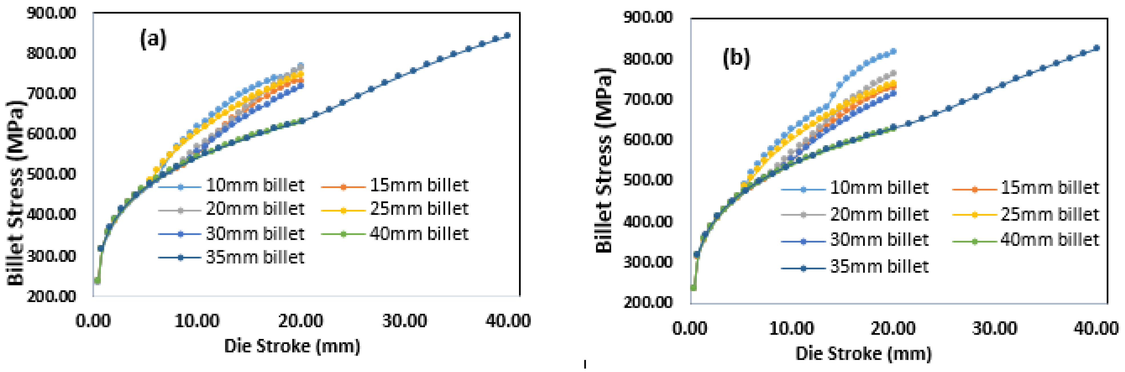
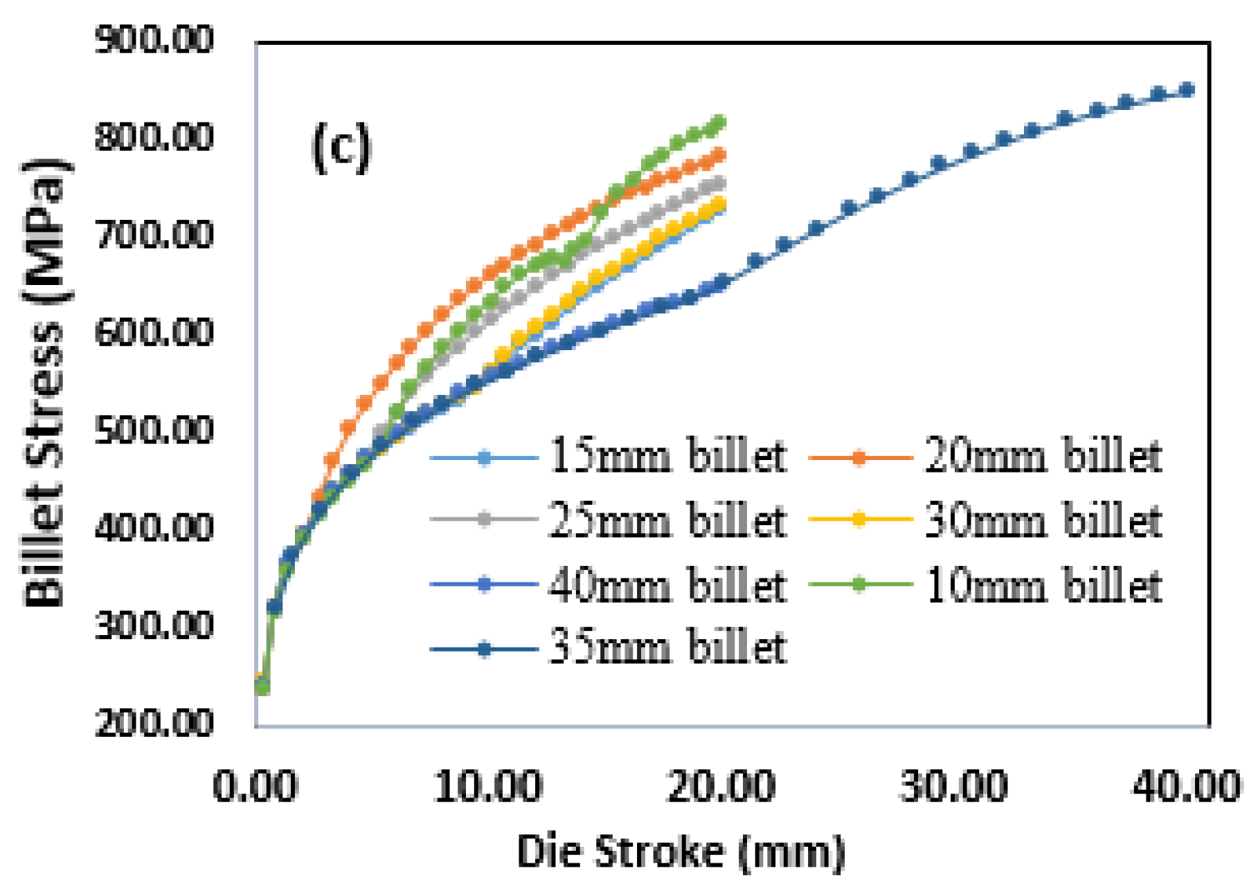
3.1. Stress vs. Die–Stroke

The data obtained from the upset forging simulations provided critical insights into the inelastic buckling behaviour of billets under compressive loading. The buckled billets exhibited significantly higher stresses than those undergoing uniform compression, as shown in Figure 3a–c (von Mises stresses extracted from the billet mid-span cross-section at 0.5 mm radial intervals) for pure aluminium under different friction coefficients. This phenomenon is attributed to additional bending stresses at the onset of buckling, which increase in magnitude with the die stroke. These bending stresses are superimposed on the existing axial and frictional stresses, causing the stress–die stroke curve to deviate from the smooth power-law relationship typically observed during uniform compression.
At the billet–die interface, frictional forces oppose the lateral motion of the workpiece material, leading to a bulging effect. To overcome this frictional resistance, a greater die force is required, the magnitude of which depends on the frictional conditions between the billet and the die faces. This study considered three lubrication conditions: furnace oil, sawdust, and dry lubrication. Increased friction (µ = 0.35) elevated overall stress magnitudes due to greater resistance to lateral material flow. For example, the stress in pure aluminium rose from approximately 750 MPa at µ = 0.12 to around 850 MPa at µ = 0.35 for a billet diameter of 40 mm. All reported stresses correspond to surface values at the mid-span cross-section (critical buckling initiation zone). However, the buckling point remained unchanged across all lubrication conditions, suggesting that friction minimally affects inelastic buckling during forging. This observation aligns with the findings of Malayappan et al. [27], who reported that while friction significantly influences the forging load, its impact on the onset of buckling is negligible. Similarly, Mohammadi et al. [28], found that friction primarily affects the stress distribution but does not significantly alter the critical buckling load.
The geometry of the billet plays a crucial role in determining the likelihood of buckling during upset forging. As the length-to-diameter (L/D) ratio decreases (i.e., the billet becomes broader), the severity of buckling diminishes, resulting in reduced bending stresses and, consequently, lower equivalent stresses in the billet. A sudden deviation from the smooth power law trend, marked by a sharp increase in stress, as observed in Figure 3a–c, indicates the onset of inelastic buckling. This behaviour is consistent with the findings of Błachut [29], who demonstrated that billets with higher L/D ratios are more prone to buckling due to increased susceptibility to bending stresses. More recently, research studies confirmed that billets with L/D ratios greater than 3.5 are highly susceptible to buckling, which aligns with the results of this study [30,31].

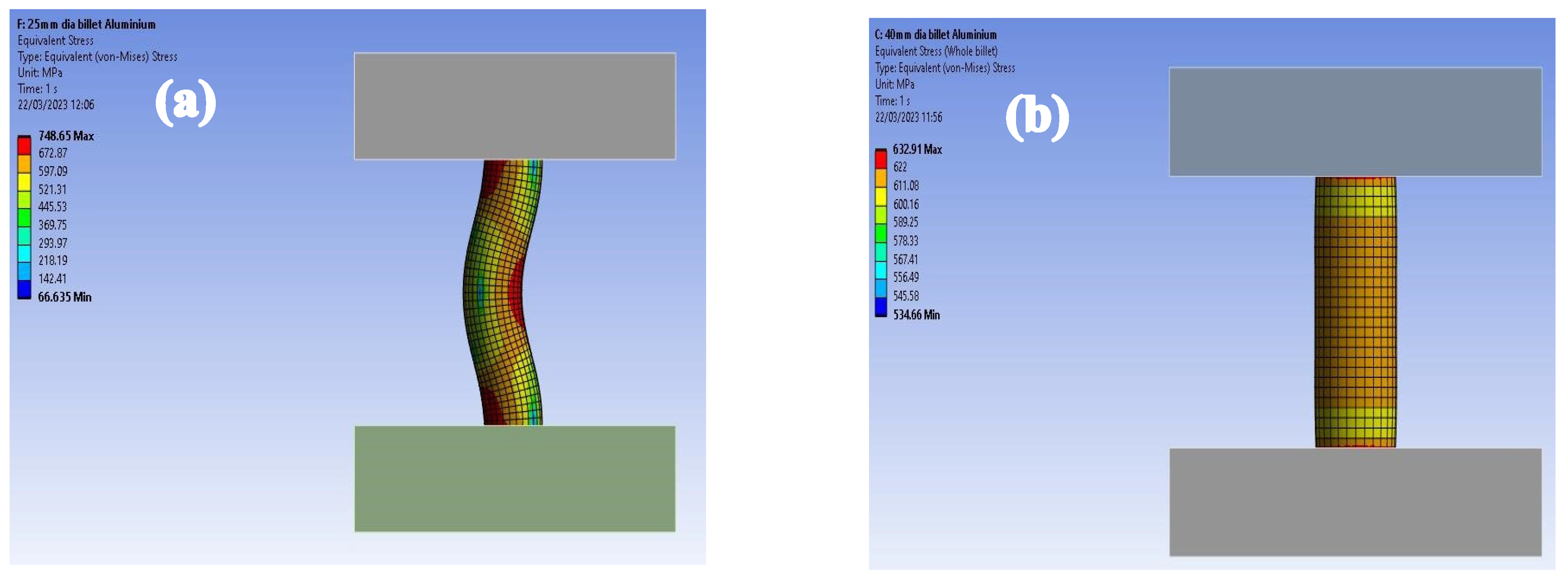
3.2. Effect of Strain Hardening Exponent on Billet Buckling

Among the plastic properties of a material f(σc, α, E, n, µ), the strain hardening exponent (n) is the most significant factor impacting the billet’s resistance to buckling due to its control over the material’s plastic response. However, the geometry of the billet—represented by the length-to-diameter ratio (α)—is equally important. While Young’s modulus (E) and compressive yield strength (σc) define elastic behaviour and stress thresholds, respectively, friction (µ) had minimal influence on the buckling onset. Thus, n and α are considered the most influential parameters in defining optimal billet geometry. Now as the billet undergoes cold working during upsetting, the material’s strength increases due to strain hardening. A higher strain hardening exponent indicates a more rapid increase in material strength with plastic deformation, thereby enhancing the billet’s resistance to buckling. For instance, in this study, the buckling of pure aluminium ceased at an L/D ratio of 3, which is consistent with the findings of Xu et al. [32], who noted that materials with higher strain hardening exponents exhibit greater resistance to buckling under compressive loads. Recent studies by Li et al. [33] have further emphasised the role of strain hardening in delaying the onset of buckling, particularly in materials with high ductility.
The stress distribution in a buckled aluminium billet (L/D = 4.8) and an aluminium billet under uniform compression (L/D = 3) is illustrated in Figure 4a,b. The buckled billet exhibits significantly higher stress concentrations, particularly at the regions of maximum bending, compared to the uniformly compressed billet. This observation agrees with the work of Dokšanović et al. [7], who highlighted that buckling leads to localised stress concentrations, which can significantly affect the structural integrity of the billet. More recently, Gong et al. [24] used finite element analysis (FEA) to demonstrate that stress concentrations in buckled billets are highly dependent on the material’s strain-hardening behaviour, further supporting the findings of this study.

3.3. Numerical Model for Predicting Billet Stress

The complexity associated with buckling during upset forging comes from its interdependence from factors such as the billet geometry, load condition, material properties, and friction/contact conditions. A stress-based numerical model for predicting buckling could be derived from the simulated data. This was done by first identifying the best-fit trendline for all stress curves, from which two distinct shape functions were obtained. A second-order polynomial and a power law relation showed a decent fit for approximating the stress behaviours for the buckled and unbuckled billets, respectively. Focusing on the former, changes in the coefficients with respect to changes in the billet geometry, material properties, and friction coefficient were analysed to identify the dependent parameters and their appropriate combinations. A model with a sufficient degree of reliability was deduced through rigorous iterations, regression analyses, and continuous comparison between the simulated data and the results of the empirical function. The numerical model, as given in Equation (1), was a function of f (σc, α, E, n, µ) with factors K1 and K2, which were changing depending on the material of the billet. Equation (1) can be expressed as follows:
σ = K 1 l n 0.01 E σ c 10 n + μ + α 10 a 2 x 2 + K 2 n 2 0.01 α + 10 μ + σ c 100 a 1 x + σ c + E 2000 a 0
where E is Young’s modulus (MPa), σc is the compressive yield strength, α is the length-to-diameter ratio, μ is the coefficient of friction, x is the die-stroke, σ is the billet stress, n is the strain-hardening exponent, K1 and K2 are factors depending on the material of the billet, a2, a1, and ao are coefficients of the second-order polynomial. The constants K1 and K2 are summarised in Table 4 for the three friction coefficients.
Table 4 above shows that K1 varies only with the material properties while K2 changes with changes in material, lubrication conditions, and the billet geometry. For this reason, K1 can be defined as a material factor Km, while K2 can be defined as a factor dependent on the process parameters, denoted as Kp. The values in Table 4 were used as a benchmark, and through careful manipulation of the dependent parameters, Equations (2) and (3) were obtained for Km and Kp, respectively, and can be expressed as follows:
K m = n 2 0.015
K p = 1 n 0.1 μ + 1 + n α
These findings are supported by Ha et al. [21], who developed a similar model for predicting stress in buckled billets and found that process parameters such as friction and billet geometry play a significant role in determining stress distribution.

4. Conclusions

This study developed a numerical model to predict buckling onset in cold upset forging by correlating critical stress deviations with billet geometry and material properties, offering three key advances over existing approaches: First, it establishes quantitative length-to-diameter thresholds (3.0–4.0) tied to strain hardening exponents, providing explicit design limits previously lacking. Second, it detects buckling earlier through stress deviation patterns rather than relying on post-buckling deformation observations. Third, the model demonstrates that while friction affects stress magnitudes, it has negligible influence on buckling initiation, a critical distinction for industrial applications. The model accurately identifies safe operating limits through two material-dependent regimes: billets with higher strain hardening (n ≥ 0.3) tolerate longer geometries (αmax = 4), while less strain-hardening materials (n < 0.3) require more compact designs (αmax = 3). This friction-independent approach enables reliable predictions for optimal billet dimensions across diverse forging conditions. Future work will expand validation to include elevated-temperature processes and anisotropic material behaviours.

Author Contributions

D.L. contributed to the simulation, writing original draft, and communication. H.M. was involved the data analysis process and contributed to the construction of the numerical model and proofreading. H.R. provided the proofread the draft article. A.A. was engaged in the article development, and data analysis. All authors have read and agreed to the published version of the manuscript.

Funding

This research received no external funding.

Data Availability Statement

Data is available on request due to ethical restrictions.

Acknowledgments

The authors thank the University of Nairobi for offering the software license.

Conflicts of Interest

The authors declare no conflicts of interest.

References

  1. Abesin Kodippili, T. Forging Preform Design Optimization for Structural Magnesium Components; University of Waterloo: Waterloo, ON, Canada, 2023. [Google Scholar]
  2. Dash, J.P. Nizam’s Mint to A People’s Museum: A Pride of Deccan Heritage and Technology; Notion Press: Chennai, India, 2023. [Google Scholar]
  3. Fan, Q.; Duan, H.; Xing, X. A review of composite materials for enhancing support, flexibility and strength in exercise. Alex. Eng. J. 2024, 94, 90–103. [Google Scholar] [CrossRef]
  4. Babaei, H.; Kiani, Y.; Reza Eslami, M. Buckling and post-buckling analysis of geometrically imperfect FGM pin-ended tubes surrounded by nonlinear elastic medium under compressive and thermal loads. Int. J. Struct. Stab. Dyn. 2019, 19, 1950089. [Google Scholar] [CrossRef]
  5. Chen, Y.; Feng, J. Group-theoretic method for efficient buckling analysis of prestressed space structures. Acta Mech. 2015, 226, 957–973. [Google Scholar] [CrossRef]
  6. Development and Research of the Billet Forging Technology in the Newly Designed Step-Wedge Dies|Request PDF. Available online: https://www.researchgate.net/publication/331348650_Development_and_Research_of_the_Billet_Forging_Technology_in_the_Newly_Designed_Step-Wedge_Dies (accessed on 27 February 2025).
  7. Dokšanović, T.; Markulak, D.; Džeba, I. State of the art review of the stability and welding of aluminium alloy elements. Građevinar 2014, 66, 115–125. [Google Scholar]
  8. Kelechava, B. Nondestructive Testing (NDT) in ASTM E1316-25—ANSI Blog. The ANSI Blog. Available online: https://blog.ansi.org/nondestructive-testing-ndt-astm-e1316/ (accessed on 11 April 2022).
  9. Donmez, A.; Fox, J.; Kim, F.; Lane, B.; Praniewicz, M.; Tondare, V.; Weaver, J.; Witherell, P. In-Process Monitoring and Non-Destructive Evaluation for Metal Additive Manufacturing Processes; National Institute of Standards and Technology: Gaithersburg, MD, USA, 2024.
  10. Rollston, C.A. Forging history: From antiquity to the modern period. In Archaeologies of Text: Archaeology, Technology, and Ethics; Eisenbrauns: Winona Lake, IN, USA, 2014; pp. 176–197. [Google Scholar]
  11. Valiulis, A.V. A History of Materials and Technologies Development; Lambert Academic Publishing: Saarbrücken, Germany, 2014. [Google Scholar]
  12. History of Forging: From Humble Beginnings to a Modern Marvel—Weldaloy Specialty Forgings. Available online: https://weldaloy.com/press-release/history-of-forging/ (accessed on 1 February 2025).
  13. Fouda, N.; El-Midany, T.; Sadoun, A.M. Bending, buckling and vibration of a functionally graded porous beam using finite elements. J. Appl. Comput. Mech. 2017, 3, 274–282. [Google Scholar]
  14. Magnucki, K.; Stasiewicz, P. Elastic buckling of a porous beam. J. Theor. Appl. Mech. 2004, 42, 859–868. [Google Scholar]
  15. The History of Forging Process|Steel Forging. Available online: https://www.steelforging.org/the-history-of-forging-process/ (accessed on 1 February 2025).
  16. Forge, A.V. Forging Ahead; Angus & Robertson: Sydney, Australia, 2009. [Google Scholar]
  17. Meyer, D.R. Networked Machinists: High-Technology Industries in Antebellum America; JHU Press: Baltimore, MD, USA, 2006. [Google Scholar]
  18. Williams, P.H. How Britain Shaped the Manufacturing World, 1851–1951; Pen and Sword History: Barnsley, UK, 2022. [Google Scholar]
  19. Jianjun, L.; Xinyun, W. Die for Forging and Stamping. In The ECPH Encyclopedia of Mining and Metallurgy; Kuangdi, X., Ed.; Springer Nature: Singapore, 2024; pp. 477–479. ISBN 978-981-9920-85-3. [Google Scholar]
  20. Bassan, F. Optimization of Industrial Processes for Forging of Carbon and Stainless Steels; Éditions Universitaires Européennes: Saarbrücken, Germany, 2015. [Google Scholar]
  21. Ha, S.; Cho, D.; Park, J.; Kim, S. A Study on the Design of Bending Process According to the Shape of Initial Billets for Bi-Metal Elbow. Metals 2022, 12, 1474. [Google Scholar] [CrossRef]
  22. Dokšanović, T.; Džeba, I.; Markulak, D. Variability of structural aluminium alloys mechanical properties. Struct. Saf. 2017, 67, 11–26. [Google Scholar] [CrossRef]
  23. Zhao, Q.; Sun, Q.; Xin, S.; Chen, Y.; Wu, C.; Wang, H.; Xu, J.; Wan, M.; Zeng, W.; Zhao, Y. High-strength titanium alloys for aerospace engineering applications: A review on melting-forging process. Mater. Sci. Eng. A 2022, 845, 143260. [Google Scholar] [CrossRef]
  24. Gong, H.; Sun, X.; Zhang, T.; Tang, H. Effects of cold expansion on residual stress of 7050 aluminium alloy frame forging. Metals 2023, 13, 732. [Google Scholar] [CrossRef]
  25. Bharti, S. Advancement in forging process: A review. Int. J. Sci. Res. 2017, 6, 465–468. [Google Scholar]
  26. Choi, Y.-J.; Lee, S.-K.; Lee, I.-K.; Hwang, S.K.; Yoon, J.C.; Choi, C.Y.; Lee, Y.S.; Jeong, M.-S. Hot forging process design of sprocket wheel and environmental effect analysis. J. Mech. Sci. Technol. 2018, 32, 2219–2225. [Google Scholar] [CrossRef]
  27. Malayappan, S.; Narayanasamy, R. An experimental analysis of upset forging of aluminium cylindrical billets considering the dissimilar frictional conditions at flat die surfaces. Int. J. Adv. Manuf. Technol. 2004, 23, 636–643. [Google Scholar] [CrossRef]
  28. Mohammadi, M.; Khedmati, M.R.; Bahmyari, E. Elastic local buckling strength analysis of stiffened aluminium plates with an emphasis on the initial deflections and welding residual stresses. Ships Offshore Struct. 2019, 14, 125–140. [Google Scholar] [CrossRef]
  29. Błachut, J. Experimental perspective on the buckling of pressure vessel components. Appl. Mech. Rev. 2014, 66, 010803. [Google Scholar] [CrossRef]
  30. Adil, H. Characterisation of a New Nanostructured Aluminium Alloy and Piston Design for Internal Combustion Engines. Ph.D. Thesis, Oxford Brookes University, Oxford, UK, 2023. [Google Scholar]
  31. Muchhala, D.; Yadav, B.N.; Pandey, A.; Chilla, V.; Shafeeq, M.M.; Gupta, G.; Sathaiah, S.; Mondal, D.P. Influences of relative density and strain rate on the mechanical properties of Al-cenosphere-SWNTs hybrid foams. Int. J. Mech. Sci. 2021, 198, 106388. [Google Scholar] [CrossRef]
  32. Xu, Z.; Tong, G.; Zhang, L.; Guo, Y. Experimental and numerical study of 7A04-T6 extruded aluminium alloy lipped angle columns in axial compression. Thin-Walled Struct. 2022, 179, 109573. [Google Scholar] [CrossRef]
  33. Li, W.; Jing, Y.; Zhou, T.; Xing, G. A new ductile fracture model for structural metals considering effects of stress state, strain hardening and micro-void shape. Thin-Walled Struct. 2022, 176, 109280. [Google Scholar] [CrossRef]
Figure 1. The upset forging setup model for a 25 mm diameter billet.
Processes 13 02078 g001
Figure 2. Fixed body-to-ground joint assignment (a); Contact and target bodies assignment (b); and Translational body-to-ground joint assignment (c).
Processes 13 02078 g002
Figure 3. Variation of billet stress against die stroke for aluminium (µ = 0.16) (a), µ = 0.12 (Furnace oil lubrication) (b); and µ = 0.35 (dry lubrication) (c).
Processes 13 02078 g003aProcesses 13 02078 g003b
Figure 4. Stress distribution of a buckled Aluminium billet (L/D = 4.8) (a), and stress distribution of an Aluminium billet under uniform compression (L/D = 3) (b).
Processes 13 02078 g004
Table 1. Summary of pure aluminium material properties used.
Elastic PropertiesPlastic Properties
Young’s modulus, MPaPoisson’s ratioCompressive yield strength, MPaStrain hardening exponent, n
71,0000.332800.2
Table 2. A guide for selecting contact and target bodies.
ItemContact SideTarget Side
MeshFineCoarse
GeometryConvexFlat or concave
MaterialSoftStiff
Table 3. Mesh sizes used and their skewness ratings.
Billet Diameter (Length = 120 mm)Mesh Size (mm)Skewness Rating
10 mm2.00.02865
15 mm2.20.040697
20 mm3.00.063374
25 mm3.00.068657
30 mm3.50.096876
35 mm4.00.083125
40 mm4.00.10409
Table 4. Summary of material constants.
Coefficient of FrictionK1 K2
101520253040
µ = 0.160.70.81.0001.1351.251.251.34
µ = 0.120.70.91.0001.251.441.441.52
µ = 0.350.70.70.70.850.850.850.85
Disclaimer/Publisher’s Note: The statements, opinions and data contained in all publications are solely those of the individual author(s) and contributor(s) and not of MDPI and/or the editor(s). MDPI and/or the editor(s) disclaim responsibility for any injury to people or property resulting from any ideas, methods, instructions or products referred to in the content.

