Article

Study of the Effects of Differences in Drill Pipe Materials, Drilling Fluids, and Formation Rock Types on the Drag Reduction Capacity of Hydraulic Oscillators

1
College of Petroleum Engineering, China University of Petroleum-Beijing, Changping, Beijing 102249, China
2
College of Mechanical and Energy Engineering, Beijing University of Technology, Chaoyang, Beijing 100124, China
3
College of Petroleum Engineering, China University of Petroleum-Beijing at Karamay, Karamay 834000, China
*
Author to whom correspondence should be addressed.
Processes 2025, 13(6), 1918; https://doi.org/10.3390/pr13061918
Submission received: 25 May 2025 / Revised: 12 June 2025 / Accepted: 13 June 2025 / Published: 17 June 2025
(This article belongs to the Section Energy Systems)

Abstract

Hydraulic oscillators can effectively reduce the frictional resistance of the horizontal well drilling column and increase mechanical drilling speed, but the influence of geological and operational conditions on the drag reduction performance of these tools has not been fully studied, resulting in the selection of hydraulic oscillators still relying mainly on field experience. This study investigates the effects of drill string material, drilling fluid, and tool type on the drag reduction capability of tools. Friction coefficients of two commonly used drill string materials (G105 steel, S135 steel) with three common formation types (sandstone, shale, and limestone) were measured under oil-based and water-based drilling fluid infiltration conditions at different speeds of movement. The experimentally obtained friction coefficients were incorporated into a nonlinear mechanical model of the drill string equipped with a hydraulic oscillator, which was solved using the finite difference method. The results showed that the drill string materials had a limited effect on tool drag reduction capabilities, while rock type and drilling fluid type had a more significant impact. The drag reduction effect of tools in oil-based drilling fluids was better than that of water-based drilling fluids. In shale, the drag reduction effect of tools was better than that in sandstone and limestone. Increasing the amplitude enhanced the drag reduction ability of tools more than increasing the vibration frequency. Increasing the amplitude and frequency of the tool in an oil-based drilling fluid environment produced a more significant increase in drag reduction than doing the same in a water-based drilling fluid environment. These findings can provide theoretical guidance for the design of output characteristics of hydraulic vibrators and field selection of tools under different drilling conditions.

1. Introduction

With the gradual depletion of conventional oil and gas resources, exploration and development activities are increasingly shifting toward deeper reservoirs and geologically complex environments, including unconventional plays. Horizontal wells and extended-reach wells have become key technologies for overcoming surface constraints and enabling the efficient development of tight oil, gas, and shale resources. However, during the drilling of long horizontal sections and high-inclination intervals, problems such as frequent drill string sticking and buckling of the pipe become increasingly prominent. These issues not only reduce the rate of penetration (ROP) but significantly increase the risk of fatigue failure of the drill string, posing serious threats to operational safety and economic performance. Studies have shown that frictional torque between the drill string and the borehole wall has become a major bottleneck limiting wellbore extension and operational efficiency. Hydraulic oscillators, which generate periodic axial vibrations, have proven effective in reducing the frictional resistance of the drill string. Field application has demonstrated that this tool can significantly improve the directional control of the tool face, extend the reach of horizontal sections, and enhance the rate of penetration, thereby providing strong support for safe and efficient drilling in deep and complex well trajectories.
At present, the research on hydrodynamic oscillators mainly focuses on two aspects: one is tool structure design and performance optimization, and the other is the vibration-damping mechanism.
In terms of tool structure design and performance optimization, in 1983, Roper, D.L [1] first proposed the concept of reducing friction between the drill string and borehole wall via axial vibration in a patent, pioneering the research into downhole vibration-assisted friction reduction tools. The FDR tool developed by Sola, K.-I [2], which adopts a bidirectional piston structure, demonstrated excellent drag-reducing capability in coiled tubing drilling operations, with experiments showing up to a 90% reduction in friction. The Agitator series hydraulic oscillators, developed by National Oilwell Varco (NOV) [3], have gained widespread recognition and application worldwide due to their outstanding performance in high-inclination well, horizontal well, and multilateral well drilling. Zhang targeting complex frictional problems in extended-reach wells, developed an S-type hydraulic oscillator with an operating frequency of 15 Hz and a pressure drop of 3–4 MPa. Field tests demonstrated a 20% increase in mechanical penetration rate. To overcome the limitations of traditional hydraulic tools in frequency and output control [4], Peng Wang proposed a self-oscillating tool based on fluid modulation principles and established the correspondence between modulation mechanisms and structural parameters, providing a theoretical foundation for subsequent design optimization [5,6]. Meanwhile, various research institutes have developed different types of hydraulic oscillators to meet diverse field requirements [7,8,9,10]. Among them, the mechanical–hydraulic hybrid tool proposed by PetroChina Daqing Drilling Company exhibited excellent durability and vibration output performance in lab tests [11].
In terms of research on the vibration-damping mechanism, Baker first reported that microvibrations could significantly reduce frictional resistance at the contact interface [12]. Pohlman further revealed that applying vertical vibrations under large displacements could effectively reduce contact pressure and the coefficient of friction, thus lowering overall friction [13]. P. Nance Richard systematically analyzed the relationship between drill string bending and wall contact friction, establishing a mathematical model for the location and magnitude of maximum contact forces, which laid the foundation for the theoretical modeling of drag-reduction tools [14]. Barakat studied hydraulic vibrations in horizontal well drill strings and found that the excitation forces generated by internal vibrations could reduce the buckling force by 11–45%, facilitating axial force transmission [15]. Nathan Wicks from Schlumberger proposed that axial vibration tools can significantly extend the reach limit of extended-reach wells. He employed transient dynamics simulations to model axial force transmission in drill strings equipped with axial vibration tools. Using a classic Coulomb friction model, the dynamic friction of moving segments was computed with a 1D dynamic model, while a 3D static model was used to calculate the contact forces and friction in stationary segments [16].
In recent years, several researchers have explored the drag-reduction mechanism of hydraulic oscillators using advanced friction models. Liu et al. [17] argued that the classical Coulomb friction theory fails to accurately characterize the dynamic friction behavior during vibration-assisted drilling. Consequently, they introduced the Dahl dynamic friction model to develop a torque prediction framework, which yielded simulation results in Simulink with only a 5.09% deviation from experimental data, demonstrating strong consistency. Similarly, Zhang et al. [18] incorporated a Coulomb friction term into the wave equation of the drill string to investigate the dynamic friction effects of hydraulic oscillators in coiled tubing drilling (CTD) and analyzed the influence of tool geometry and bore-hole conditions on performance. Zheng et al. [19] established a dynamic model incorporating nonlinear contact and the transition between static and kinetic friction, revealing how contact nonlinearity and excitation parameters affect the time-varying friction force and drag-reduction efficiency. Shi et al. [20,21,22] developed a mechanical model of the drill string with hydraulic oscillators, identifying excitation force amplitude, frequency, and the number of oscillators as key factors influencing drag-reduction performance, and validated their findings through simulations and field case studies.
Previous studies have primarily focused on the structural design and field deployment of hydraulic oscillators, as well as the impact of excitation parameter variations within drill string dynamic models incorporating such tools. However, the effects of drill string material, drilling fluid properties, and formation lithology on drag-reduction performance have been largely overlooked. As a result, the applicability of existing conclusions across different drilling conditions remains limited, hindering the development of systematic design strategies for excitation parameters.
In contrast, the present study establishes a drill string mechanical model incorporating hydraulic oscillators while accounting for the nonlinear characteristics of frictional forces. This model was integrated with experimentally measured friction data for various combinations of drill string materials, drilling fluids, and rock samples under different sliding velocities. The influence of the coupled mechanisms of vibration parameters and formation environment on drag-reduction performance was systematically investigated. Field case analyses were also conducted, and excitation parameter optimization strategies are proposed for diverse drilling scenarios. This study bridges the gap between frictional behavior and excitation parameter design, providing both theoretical foundations and practical guidance for the adaptive optimization and field implementation of hydraulic oscillators.

2. Theoretical Models

The following assumptions and descriptions were made regarding the model:
(1)
The drill string was modeled as an elastic rod with a circular cross-section.
(2)
The drill string was considered in uniform contact with the borehole wall and nonrotating.
(3)
Only axial vibrations were considered; lateral and torsional vibrations were neglected.
(4)
The Stribeck model was adopted to depict the dynamic friction between the drill string and the well-bore.
(5)
The damping effect of drill string materials and formation rocks on the drill pipe was represented by the friction damping term in the vibration equation. The friction damping coefficient was obtained through laboratory friction coefficient measurement experiments.
(6)
The damping effect of drilling fluid on the drill pipe was represented by the viscous damping term in the vibration equation. The viscous damping coefficient varied with the type of drilling fluid.
(7)
The hydraulic oscillator was simplified as a high-stiffness spring-mass-damping system, and the excitation effect of the tool was modeled as an equivalent resonant force.
(8)
The drill bit was considered a boundary with a known axial force, and its axial displacement was calculated as the system output.
A schematic diagram of the drill string equipped with a hydraulic oscillator is shown in Figure 1.

2.1. Evaluation Index for Drag Reduction

In this study, the increase in weight on bit (∆WOB) after excitation by the hydraulic oscillator was used as the evaluation index for its drag-reducing capability. The calculation formula is:
Δ W O B = i = 1 n   f p r e , i f a v g , i Δ x
where n is the number of drill string elements; f pre   , i is the frictional resistance of the element before oscillator excitation; f avg   , i is the average frictional resistance of the element after oscillator excitation; and Δ x is the length of each element.

2.2. Vibration Equation

Assuming the drill string is initially at rest and composed of multiple discrete elements, the force balance for a single element yields the following mechanical equilibrium equation:
F + d F + q d c o s θ d s π D o C v d s F μ q d s i n θ d s = 0
Since F = E A s U t ∂s, the above equation can be rewritten as:
2 U s 2 = μ q d s i n θ + π D o C v q d c o s θ E A s
When the oscillator works, the static friction force on the drill string near the oscillator is converted into dynamic friction force. Then, the vibration equation of the drill string is written as follows:
F + d F + q d c o s θ d s π D o C v d s F μ q d s i n θ d s = ρ s A s d s 2 U t 2
The above equation can be rewritten as:
E ρ s 2 U s 2 + q d cos θ ρ s A s π D o C ρ s A s U t + v 0 F f ρ s A s = 2 U t 2
In the equation, E is the Young’s modulus; ρ s is the density of the drill string; U is the axial displacement; s is the length coordinate of the drill string element; q d is the buoyant weight per unit length; θ is the wellbore inclination; A s is the cross-sectional area; D o is the diameter of the drill string; C is the viscosity coefficient of the drilling fluid; v 0 is the fluid flow velocity; and F f is the friction force between the drill string and the borehole wall.

2.3. Friction Model

The frictional force between the drill string and the borehole wall was modeled using the Stribeck curve [23], which describes the friction as a function of relative velocity. In horizontal wells, the typical rate of penetration ranges from a few to several ten meters per hour, corresponding to low-speed motion. Experimental results have shown that the Stribeck model can achieve over 90% accuracy in predicting friction at low speeds [24,25,26]. The Stribeck model is given by:
f v = f c + f s f c e v v s δ
In the equation, f s is the maximum static friction force; f c is the Coulomb friction force; v is the relative velocity; v s is the characteristic velocity; and δ is the exponential parameter.

3. Numerical Method

3.1. Finite Difference Method

The drill string was discretized into multiple spatial elements. A small time step was introduced to describe the dynamic behavior of each element under the influence of the hydraulic oscillator. Let U i j denote the axial displacement of the i-th element at time step j. Using explicit central difference schemes, Equations (3) and (5) can be expressed as:
U i + 1 j 2 U i j + U i 1 j Δ s i 2 = μ i j q d s i n θ + π D o C v i j q d c o s θ E A s
E ρ s U i + 1 j 2 U i j + U i 1 j Δ s i 2 + q cos θ ρ s A s π D C ρ s A U i j + 1 U i j Δ t + v L T f d + f s f d e U i j + 1 U i j Δ t δ sgn v ρ s A s = U i j + 1 2 U i j + U i j 1 Δ t 2

3.2. Boundary and Initial Conditions

The solution of the drill string dynamics requires both initial and boundary conditions. Initially, the drill string is in static equilibrium, given by:
U t = 0 = U 0 d U d t t = 0 = 0
In the equation, U 0 is the initial displacement.
The top end of the drill string is connected to the traveling block, and its displacement is governed by the block’s movement:
U s = 0 = U h
In the equation, U h is the displacement of the hook.
At the bottom end, the drill string is connected to the bit, and the axial force equals the negative of the weight on bit:
E A s d U s n d s = W O B t
In the equation, W O B is the weight on bit.

3.3. Continuity Conditions

According to the working mechanism of the hydraulic oscillator, it was modeled as a series combination of a high-stiffness spring and an excitation force, as shown in Figure 1. The continuity conditions at the upper and lower ends of the oscillator are given by:
F u = E A s U u s n d s F d = E A s U d s n d s F d = K U d s n U u s n F u F d = F e t
In the equation, F u , U u are the axial force and displacement at the upper end of the oscillator; F d ,   U d are the axial force and displacement at the lower end; K is the equivalent stiffness of the oscillator; and F e is the excitation force.
The model was solved using the explicit finite difference method, which provides higher computational efficiency than implicit schemes. The time step must be sufficiently small to account for the nonlinear frictional behavior and to ensure that the computational error remains within acceptable bounds.

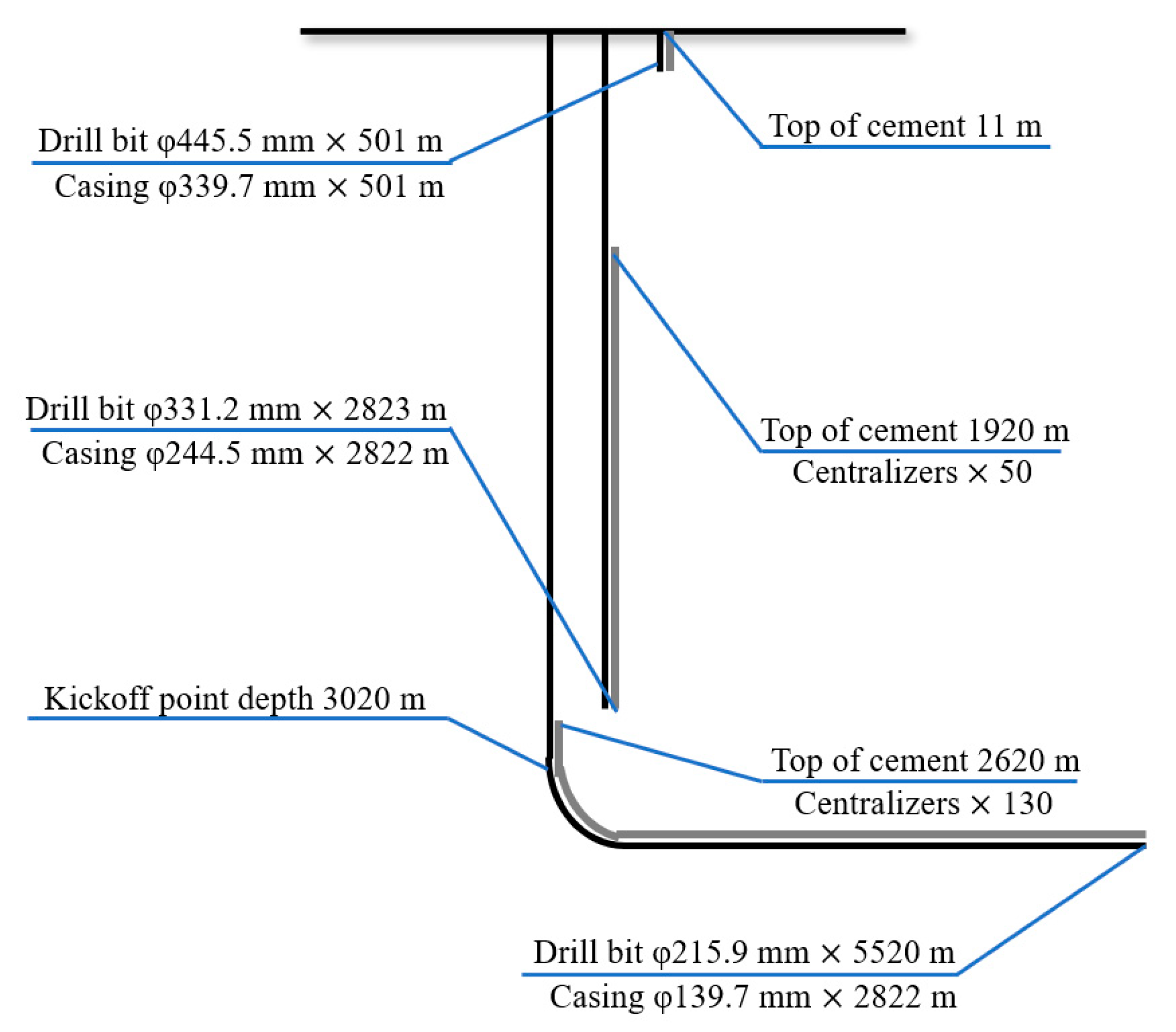
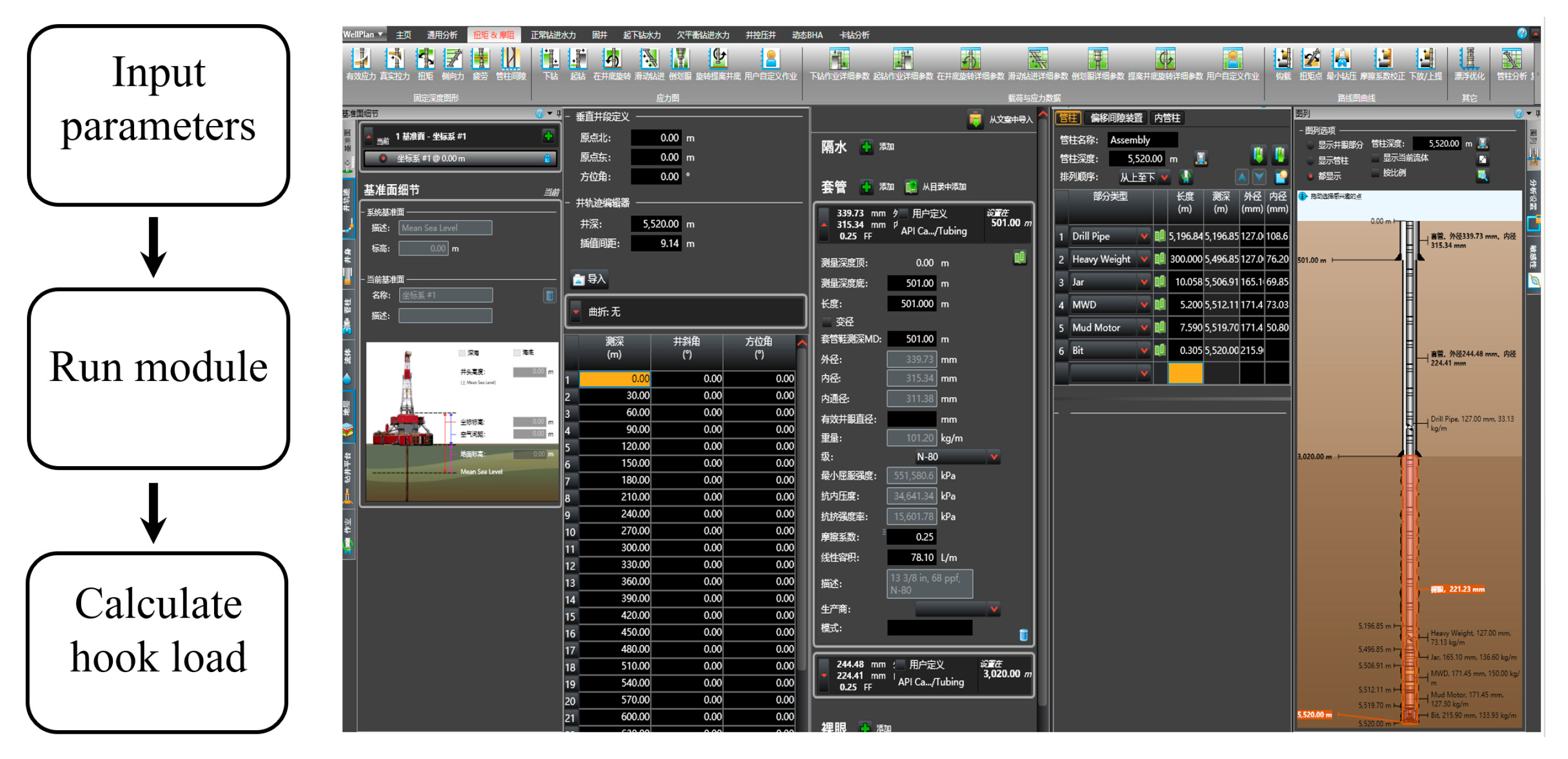
3.4. Model Validation

The proposed mechanical model of the drill string was validated using a case study. JHW-X is a horizontal well in northwestern China. The kickoff point is at a depth of 3020 m, and the horizontal section has an inclination angle close to 90°, with a total depth of 5520 m. The wellbore structure is illustrated in Figure 2.
The upper part of the drill string consisted of 5″ drill pipes (approximately 5520 m), and the lower part used 6 ½″ drill pipes. The average rate of penetration was 14.25 m/h, with an initial WOB of 50 kN. The hydraulic oscillator applied a sinusoidal excitation force with an amplitude of 30 kN and a frequency of 16 Hz. The rated pump pressure was 28 MPa. In the simulation, the time step was set to 1.25 ×10⁻⁴ s, and the spatial step was 0.6 m.
To validate the computational accuracy of the proposed model, its simulation results were compared with those obtained from the commercial drilling software Landmark, version EDT 5000.14. Developed by Halliburton, Landmark’s WellPlan module enables the simulation of hook load versus depth by incorporating critical input parameters, including wellbore geometry, drill string configuration, drilling fluid properties, and formation friction coefficients. Figure 3 illustrates the basic workflow for performing hook load simulations using this module, including parameter input, module execution, and result generation. In the simulation, the drill string material was specified as S135 steel, with a Young’s modulus of 202 GPa and a Poisson’s ratio of 0.3. The drilling fluid was set as an oil-based mud with a density of 1.35 g/cm3. To ensure consistency in boundary conditions, the horizontal section of the well was modeled as a homogeneous shale formation with uniform thermomechanical properties. Upon completing all parameter configurations, the software was executed to generate the hook load-versus-depth curve.
The simulation results obtained from Landmark were compared with those from the proposed model and field measurements. The comparison results are shown on Figure 4. The Landmark simulation had a maximum error of 13.12% and an average error of 6.01%, whereas the proposed model showed a maximum error of 6.17% and an average error of 3.32%. These results indicated that the model had high computational accuracy and could serve as a reliable basis for subsequent theoretical analyses.

4. Friction Coefficient Measurement Experiments

Laboratory experiments were conducted to measure the maximum static and kinetic friction coefficients between drill string materials and various rock samples under drilling fluid-wetted conditions. These tests aimed to obtain the relationship curves between sliding velocity and friction coefficients, providing essential data support for analyzing the drag reduction performance of hydraulic oscillators.

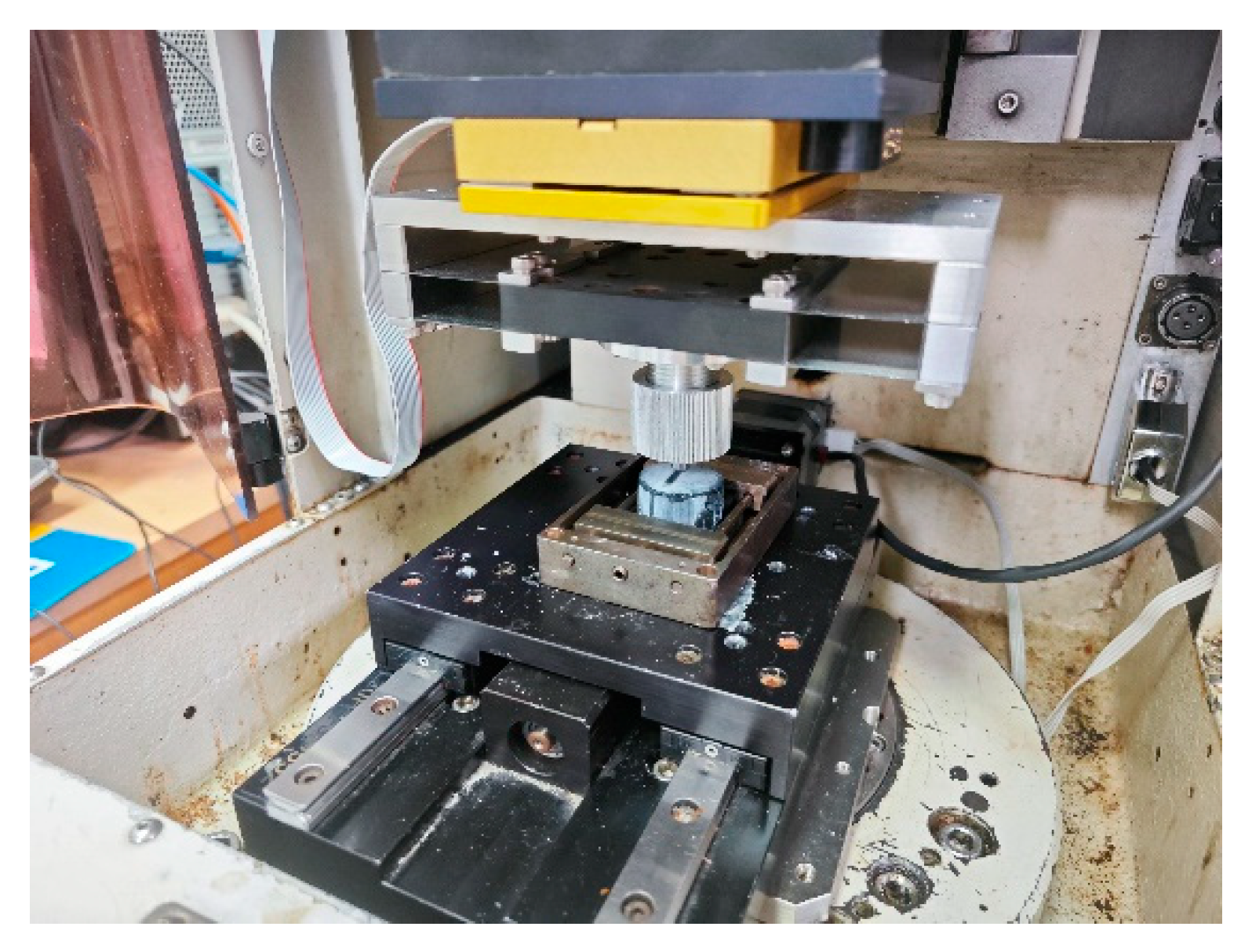
4.1. Experimental Apparatus

A linear reciprocating tribometer, as shown in Figure 5, was employed to measure friction coefficients. In the experiment, rock samples were mounted on the lower fixture, which was firmly attached to the base platform via threaded connections. Drill string material samples were installed on the upper fixture, which was driven by a servo motor allowing precise control of stroke and reciprocation frequency, thereby accurately controlling the sliding velocity. The apparatus was equipped with high-precision sensors to automatically record key parameters such as friction coefficient and velocity at a preset sampling rate, enabling comprehensive data acquisition and storage for subsequent curve plotting and analysis.

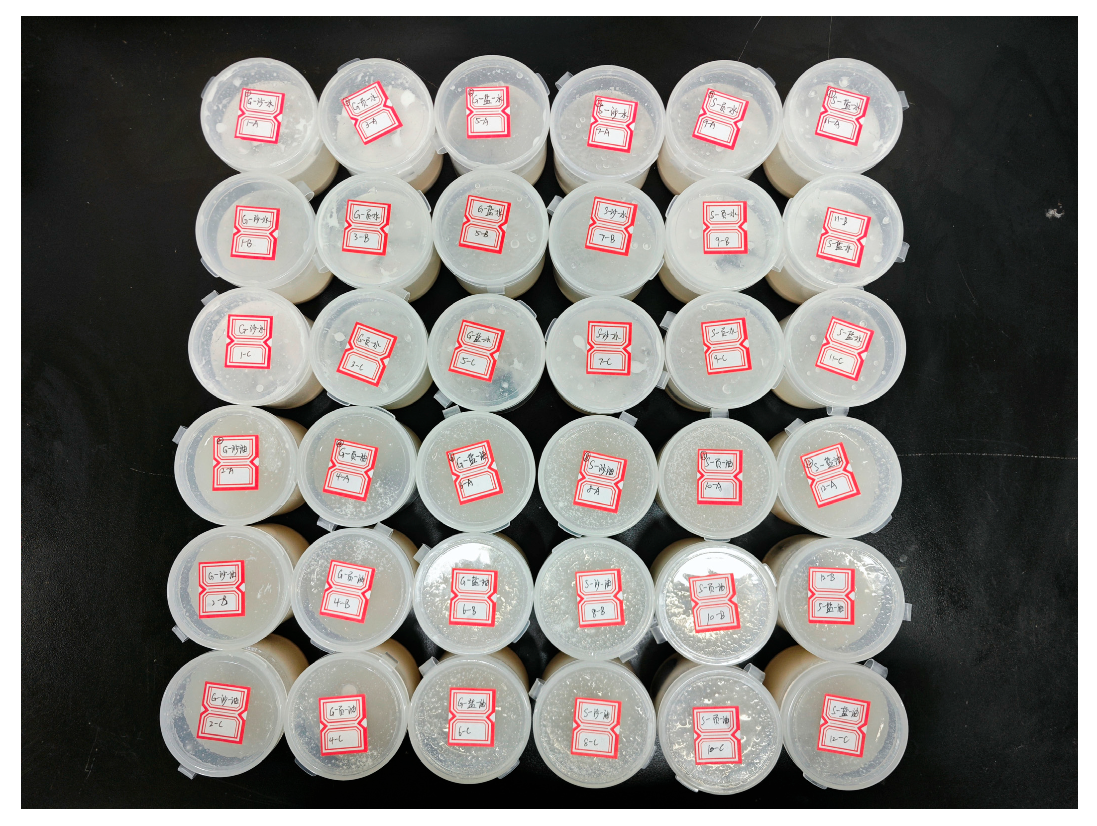
4.2. Experimental Materials

To realistically simulate the contact friction conditions between the drill string and formations in horizontal drilling with hydraulic oscillators, two widely used API-grade drill string steels—G105 and S135—were selected. Three common rock types encountered in horizontal wells were tested: sandstone, shale, and limestone. One water-based and one oil-based drilling fluid commonly used in the field were chosen as lubricants. As the frictional properties of rock samples change during immersion in drilling fluids—typically decreasing rapidly and stabilizing after about 12 h—all rock samples were presoaked for 24 h before testing to ensure the stability and reliability of the measured data, as shown in Figure 6.

4.3. Experimental Design

To comprehensively analyze the effects of different drill pipe materials, drilling fluid types, and rock types on the drag reduction capacity of tools, a full factorial design with three factors was adopted, resulting in 12 experimental groups. Each group was tested three times with new samples to improve data reliability, as shown in Figure 7. Based on typical mechanical penetration rates and localized slipping characteristics under hydraulic oscillator vibration in horizontal wells, the sliding velocity was set between 0.1 mm/s and 6 mm/s. A step-loading protocol was applied, dividing the velocity into 13 incremental stages, each lasting 3 min. The kinetic friction coefficient was recorded at each stage, facilitating the construction of complete velocity–friction coefficient curves.

5. Results and Discussion

The experimentally obtained friction coefficients for different combinations of drill string materials, drilling fluids, and rock types across varying sliding velocities were fitted using the nonlinear Stribeck friction model and incorporated into the established drill string mechanical model with hydraulic oscillators. The influence of steel grade, drilling fluid, and rock type on the drag reduction performance of the hydraulic oscillator was systematically analyzed through numerical simulations. Additionally, the effects of varying vibration amplitude and frequency on the tool’s drag reduction capability were investigated under different combinations of “steel–drilling fluid–rock.”

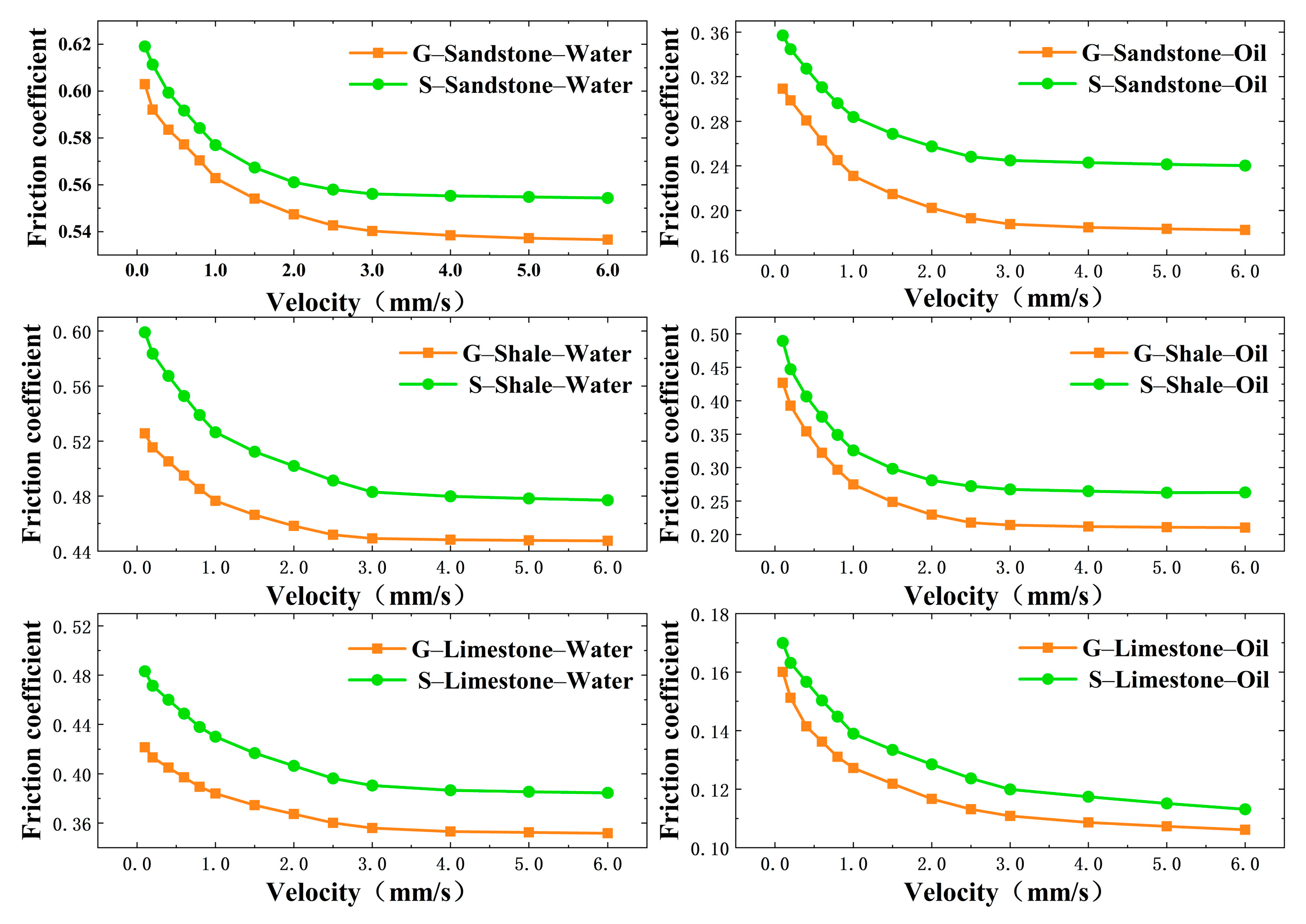
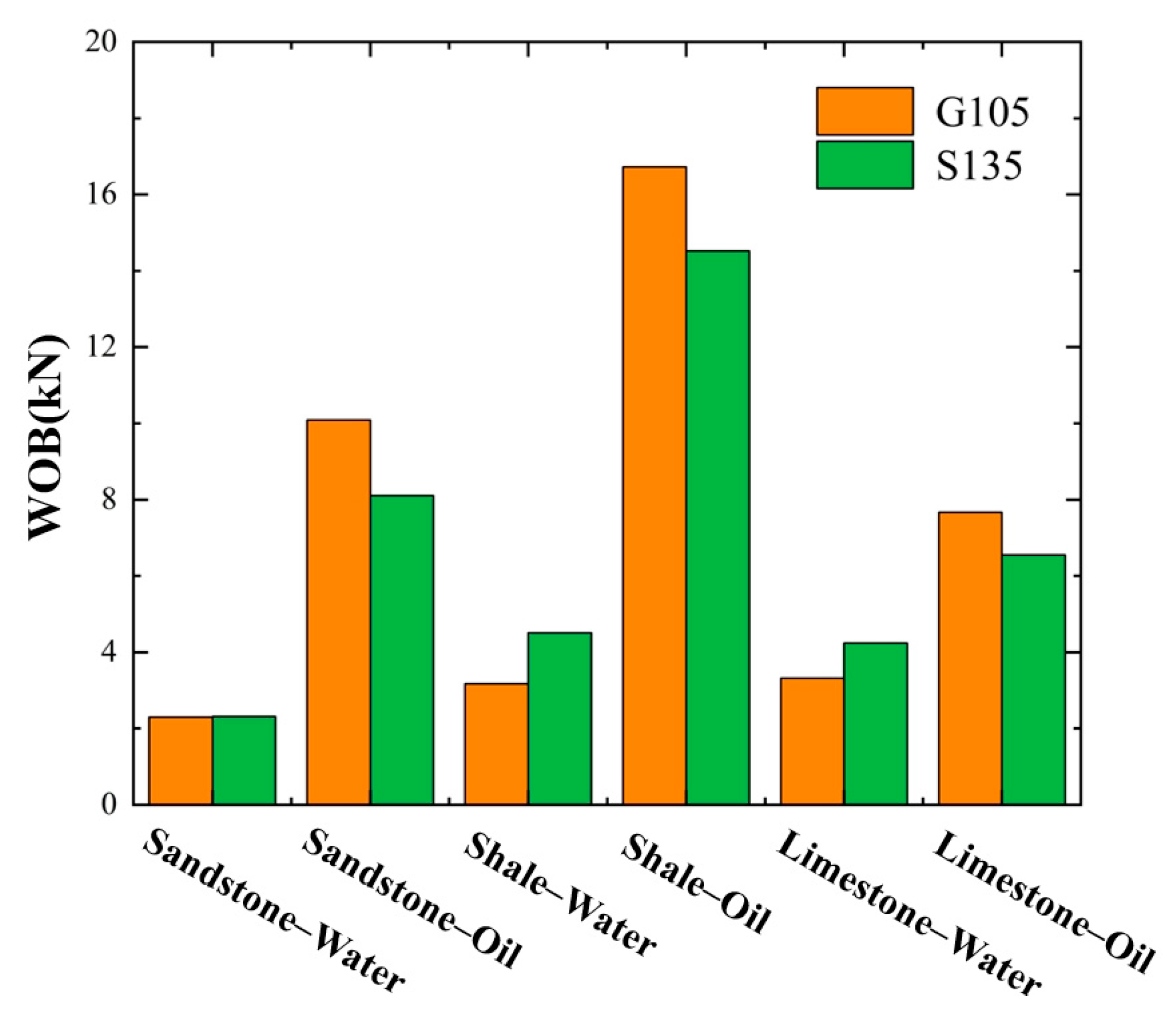
5.1. Effects of Drill String Material

Figure 8 presents the variation in friction coefficients with sliding velocity for G105 and S135 steels. The results showed decreasing trends for the friction coefficients with increasing velocity for both materials. S135 exhibited slightly higher friction coefficients than G105, likely due to its higher hardness, which led to more localized plastic deformation and greater real contact area with rock under the same load.
To further investigate the influence of drill string material on the drag reduction performance of hydraulic oscillators, comparative simulations were conducted using hydraulic oscillators with identical vibration amplitudes and frequencies. As shown in Figure 9, when S135 steel was used as the drill string material, the resulting increase in weight on bit (WOB) was slightly lower than that achieved with G105 steel. This was attributed to the higher friction coefficient between S135 steel and the rock interface, which limited the effective transmission of vibrational energy and thereby diminished the drag reduction effectiveness of the tool. Overall, the drill string material exerted a relatively minor influence on the performance of the hydraulic oscillator, indicating that it is a secondary factor in the drag reduction mechanism.

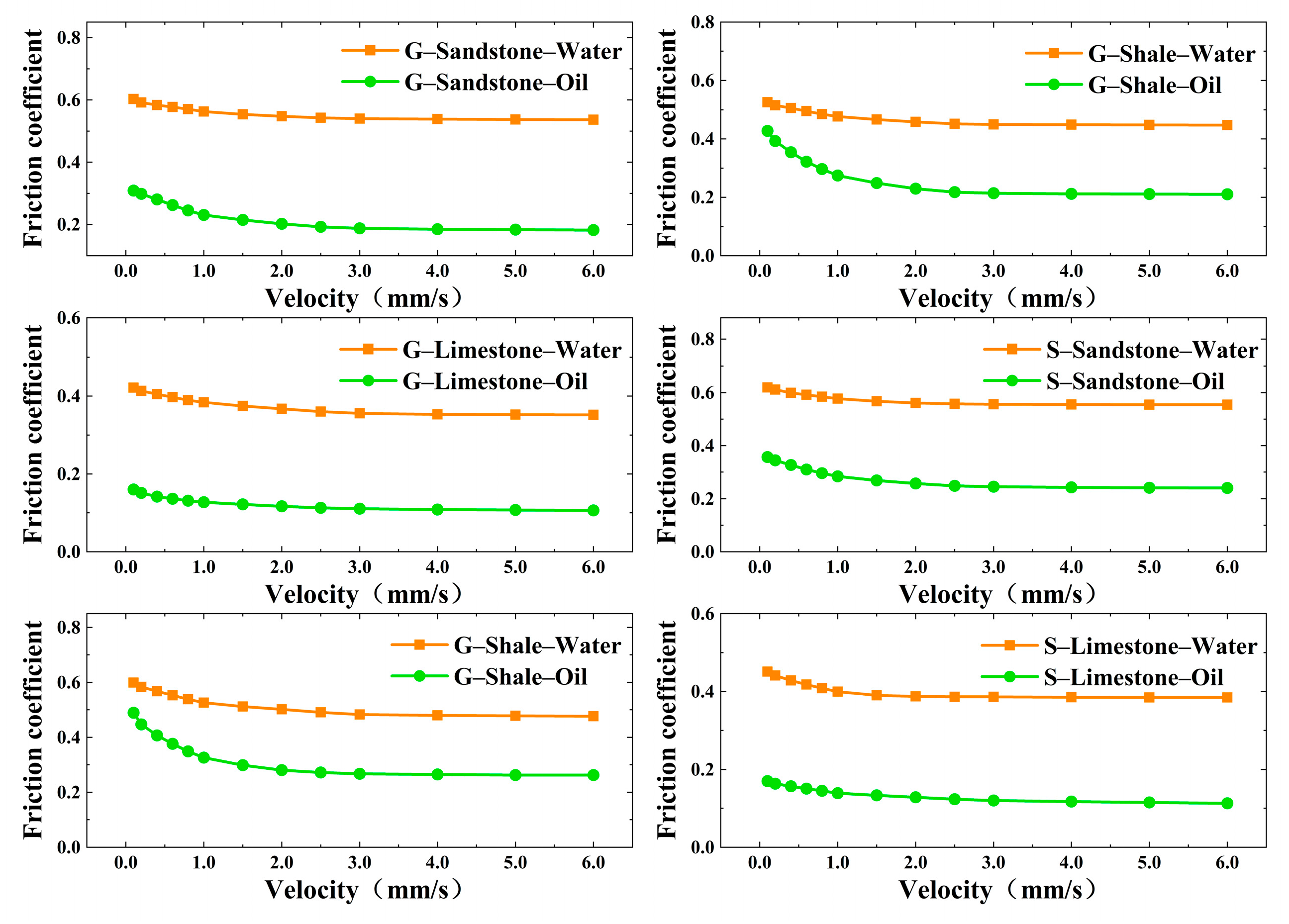
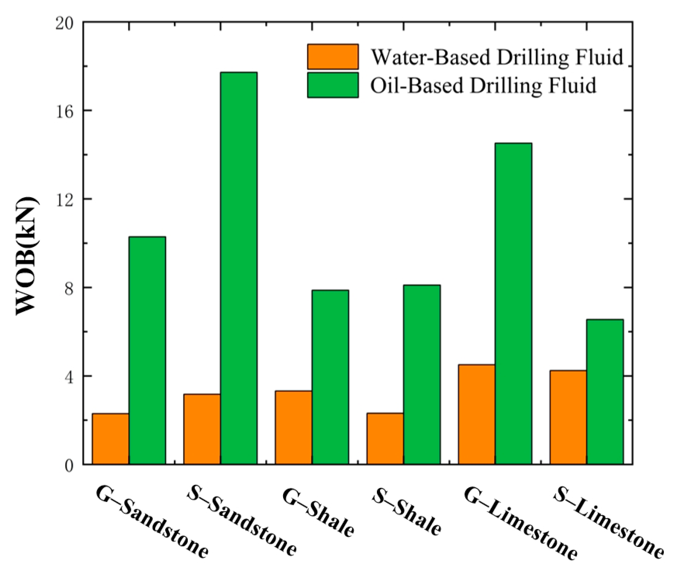
5.2. Effects of Drilling Fluid Type

Figure 10 presents the variation in friction coefficients with sliding velocity for different combinations of drill string materials and rock types under lubrication by water-based and oil-based drilling fluids. The results showed a general decreasing trend in friction coefficients as sliding velocity increased. For all steel–rock pairings, the friction coefficients under oil-based drilling fluid conditions were consistently lower than those under water-based fluids. This was primarily due to organic lubricating components in oil-based fluids, which facilitated the formation of more stable boundary lubrication films at the metal–rock interface, thereby reducing the interfacial shear strength. In contrast, the lubrication films formed by water-based fluids exhibited lower stability, resulting in higher friction coefficients.
To further examine the influence of drilling fluid type on the drag reduction performance of hydraulic oscillators, a case study was conducted using identical vibration amplitude and frequency settings. The results, illustrated in Figure 11, revealed that all drill string material–rock type combinations achieved significantly higher increases in weight on bit (WOB) when using oil-based drilling fluids compared with water-based fluids. Notably, the “G105 steel–shale” combination achieved the greatest WOB increase, reaching 17.7 kN. For the other combinations, the oil-based fluid provided WOB enhancements in the range of 2–10 kN.
These findings highlight that the type of drilling fluid has a substantial impact on the drag reduction effectiveness of hydraulic oscillators, making it a primary influencing factor. Oil-based drilling fluids are more conducive to the release and transmission of axial vibrational energy and are therefore recommended for use under high-friction drilling conditions.

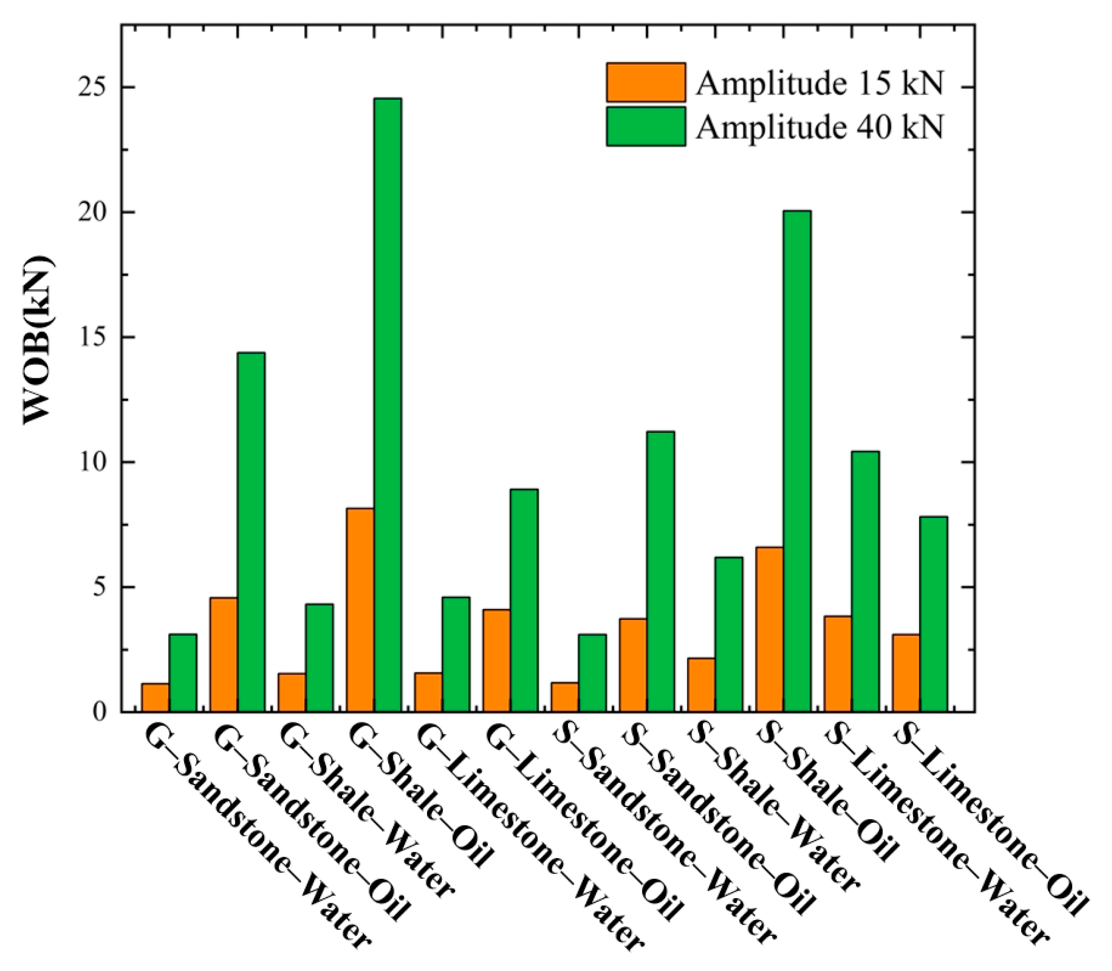
5.3. Effects of Rock Type

Figure 12 illustrates the variation in friction coefficients with sliding velocity for different drill string materials in contact with sandstone, shale, and limestone under lubrication by water-based and oil-based drilling fluids. Overall, the friction coefficients decreased as sliding velocity increased. At a given sliding velocity, the friction coefficients in water-based drilling fluid followed the order sandstone > shale > limestone, whereas in oil-based drilling fluid, the order became shale > sandstone > limestone. This difference arose from the combined effects of rock hardness, surface roughness, and abrasive particle generation capability. Because of the relatively weak lubricating performance of water-based drilling fluids, the friction coefficient was primarily governed by the intrinsic properties of the rock. In contrast, oil-based fluids provide stronger lubrication, such that the lubricating film formed during motion could effectively cover rough surfaces, mitigating the influence of sandstone’s surface roughness on friction behavior.
To further analyze the influence of rock type on the drag reduction performance of hydraulic oscillators, a case study was conducted using oscillators with identical vibration amplitude and frequency. The results are shown in Figure 13. Under water-based drilling fluid, the magnitude of weight-on-bit (WOB) increase followed the order shale > limestone > sandstone, whereas under oil-based drilling fluid, the order changed to shale > sandstone > limestone. According to Equation (1), the WOB increment is subject to the dual influence of both the difference in the frictional resistance of the drill string microsegments before and after vibration and the vibration propagation distance. The shale formation exhibited the highest WOB increase under both fluid types, indicating that it offers advantages in both friction reduction and vibration propagation. However, the relative performance of sandstone and limestone reversed with the change in fluid type. In water-based fluids, sandstone’s high friction coefficient led to shorter vibration transmission distances and the poorest drag reduction performance. In oil-based fluids, the increased frictional variation and improved lubrication in sandstone enhanced the drag reduction performance, surpassing that of limestone. Based on the above analysis, rock type has a significant impact on the drag reduction capability of hydraulic oscillators and should be regarded as a key factor in tool design and field application.

5.4. Effects of Vibration Frequency and Amplitude

Figure 14 and Figure 15 show the trends in weight-on-bit (WOB) increment under various combinations of drill string material, drilling fluid type, and formation rock when the vibration frequency and amplitude of the hydraulic oscillator were varied. The results indicated that increasing either vibration frequency or amplitude led to a certain degree of improvement in WOB increment. However, the enhancement effect of increased amplitude was significantly greater than that of increased frequency. This is because the WOB increment is influenced by both the change in the microelemental friction resistance of the drill string before and after vibration and the effective transmission distance of vibration. Increasing the vibration amplitude can substantially enlarge the friction resistance variation and extend the vibration propagation range, whereas increasing the frequency has relatively limited effects on these aspects.
Further analysis revealed that whether by increasing amplitude or frequency, the corresponding WOB increment tended to be more pronounced in oil-based drilling fluids than in water-based fluids. This was attributed to the superior lubricating performance of oil-based fluids, which significantly reduced adhesive friction at the drill string–formation interface. The applied vibration more easily disrupted the boundary lubrication film, resulting in a larger differential in friction resistance. Additionally, lower interfacial damping in oil-based fluids facilitated longer vibration propagation distances. Enhanced lubrication thus amplified the drag-reduction benefits brought by variations in amplitude and frequency. Therefore, provided that the energy consumption of the drilling fluid remains acceptable, the design of hydraulic oscillators should prioritize increasing vibration amplitude to achieve better drag reduction performance.

6. Conclusions

(1)
A mechanical model of a hydraulic-oscillator-equipped drill string incorporating nonlinear friction behavior was established. Integrated with experimental friction data, the effects of drill string material, drilling fluid type, rock type, and tool vibration parameters on the hydraulic oscillator’s friction reduction capability were systematically analyzed.
(2)
The influence of drill string material on the drag reduction performance of the hydraulic oscillator was limited. When applied to horizontal wells, the tool exhibited slightly better performance with G105 steel drill strings than with those made of S135 steel.
(3)
The type of drilling fluid significantly affected the drag reduction capability of the hydraulic oscillator; oil-based drilling fluids form more stable lubricating films and are preferred in horizontal well sections with high frictional resistance.
(4)
The type of rock had a pronounced impact on the drag reduction efficiency of the hydraulic oscillator. In sandstone formations, the use of oil-based fluids combined with high-excitation hydraulic oscillators is recommended. In shale formations, tools with medium excitation intensity are sufficient to achieve effective drag reduction. For limestone formations, oil-based fluids with high excitation parameters can enhance drag reduction, though energy consumption should also be considered.
(5)
Vibration parameters strongly influenced the tool’s drag reduction performance, with increases in amplitude contributing significantly more to efficiency improvements than increases in frequency. Therefore, when designing tool vibration parameters, priority should be given to increasing amplitude to achieve better drag reduction outcomes.

Author Contributions

Writing—original draft, X.H.; formal analysis, X.H.; data curation, X.H. and T.C.; funding acquisition, G.L. and J.L.; methodology, X.H., W.W., S.L. and L.W.; validation, X.H. All authors have read and agreed to the published version of the manuscript.

Funding

This paper was supported by the National Natural Science Foundation (52227804) and the PetroChina–China University of Petroleum (Beijing) Strategic Cooperation Project (ZLZX2020-01).

Data Availability Statement

The original contributions presented in this study are included in the article. Further inquiries can be directed at the corresponding author.

Conflicts of Interest

The authors declare no conflict of interest.

References and Note

  1. Roper, D.L. Reduction of the Frictional Coefficient in a Borehole by the Use of Vibration. U.S. Patent 4,398,594, 16 August 1983. [Google Scholar]
  2. Sola, K.-I.; Lund, B. New downhole tool for coiled tubing extended reach. In Proceedings of the SPE/ICoTA Coiled Tubing Roundtable, Houston, TX, USA, 5–6 April 2000. [Google Scholar]
  3. Newman, K.; Burnett, T.; Pursell, J.; Gouasmia, O. Modeling the affect of a downhole vibrator. In Proceedings of the SPE/ICoTA Coiled Tubing & Well Intervention Conference and Exhibition, The Woodlands, TX, USA, 31 March–1 April 2009; p. SPE-121752-MS. [Google Scholar]
  4. Zhang, H.; Yu, W.; Chen, Z.-S.; Cai, W. Development of hydropulse axial-oscillation friction-reduce tool. Oil Field Equip. 2014, 43, 73–77. [Google Scholar]
  5. Wang, P.; Ni, H.; Wang, R. A novel vibration drilling tool used for reducing friction and improving the penetration rate of petroleum drilling. J. Pet. Sci. Eng. 2018, 165, 436–443. [Google Scholar] [CrossRef]
  6. Wang, P.; Ni, H.; Wang, X.; Wang, R. Modelling the load transfer and tool surface for friction reduction drilling by vibrating drill-string. J. Pet. Sci. Eng. 2018, 164, 333–343. [Google Scholar] [CrossRef]
  7. Liu, H.; Fu, Q.; Zhou, J.; Wu, X.; Zhao, P.; Wang, J. Vibration frequency analysis of jetting hydraulic oscillator. China Pet. Mach. 2016, 44, 20–24. [Google Scholar]
  8. Nie, Y.; Zhang, Y.; Fan, X.; Zhao, C.; Zhang, H. Development and application of self-excited vortex control hydraulic oscillator. Pet. Drill. Tech. 2019, 47, 74–79. [Google Scholar]
  9. Wang, W.; Li, G.; Li, J.; Zha, C.; Chen, T. Structural design and performance parameters of valve-type hydraulic oscillator. China Pet. Mach. 2022, 50, 17–23. [Google Scholar]
  10. Wang, J.; Zhang, F.; Yang, C.; Liu, H.; Yu, C.; Zhang, Z. Development and test of low-pressure high energy and long life hydraulic oscillator. Oil Field Equip. 2024, 53, 30–35. [Google Scholar]
  11. Bo, L. Development and pilot test of hydro-oscillator. Pet. Drill. Tech. 2014, 42, 111–113. [Google Scholar]
  12. Baker, H.D.; Cook, W.; Fuller, D.D. In Proceedings of the First U.S. National Congress of Applied Mechanics Held at Illinois Institute of Technology, Chicago, IL, USA, 11–16 June 1951.
  13. Pohlman, R.; Lehfeldt, E. Influence of ultrasonic vibration on metallic friction. Ultrasonics 1966, 4, 178–185. [Google Scholar] [CrossRef]
  14. Pance, R.; Hassan, A. A study of the buckling of rotary drilling strings. AIAA J. 1971, 9, 1385–1390. [Google Scholar]
  15. Barakat, E.R.; Miska, S.; Yu, M.; Takach, N. The effect of hydraulic vibrations on initiation of buckling and axial force transfer for helically buckled pipes at simulated horizontal wellbore conditions. In Proceedings of the SPE/IADC Drilling Conference, Amsterdam, The Netherlands, 20–22 February 2007; p. SPE-105123-MS. [Google Scholar]
  16. Wicks, N.; Pabon, J.; Zheng, A. Modeling and field trials of the effective tractoring force of axial vibration tools. In Proceedings of the SPE Deepwater Drilling and Completions Conference, Galveston, TX, USA, 10–11 September 2014; p. SPE D021S014R004. [Google Scholar]
  17. Liu, Y.; Chen, P.; Wang, X.; Ma, T. Modeling friction-reducing performance of an axial oscillation tool using dynamic friction model. J. Nat. Gas Sci. Eng. 2016, 33, 397–404. [Google Scholar] [CrossRef]
  18. Zhang, W.; Shi, H.; Li, G.; Song, X.; Zhao, H. Mechanism analysis of friction reduction in coiled tubing drilling with axial vibratory tool. J. Pet. Sci. Eng. 2019, 175, 324–337. [Google Scholar] [CrossRef]
  19. Zheng, X.; Agarwal, V.; Liu, X.; Balachandran, B. Nonlinear instabilities and control of drill-string stick-slip vibrations with consideration of state-dependent delay. J. Sound Vib. 2020, 473, 115235. [Google Scholar] [CrossRef]
  20. Shi, X.; Huang, W.; Gao, D. Mechanical models of drillstrings with drag reduction oscillators and optimal design methods of vibration parameters in horizontal drilling. Geoenergy Sci. Eng. 2023, 224, 211585. [Google Scholar] [CrossRef]
  21. Shi, X.; Huang, W.; Gao, D.; Zhu, N. Optimal design of drag reduction oscillators by considering drillstring fatigue and hydraulic loss in sliding drilling. J. Pet. Sci. Eng. 2022, 208, 109572. [Google Scholar] [CrossRef]
  22. Shi, X.; Huang, W.-J.; Gao, D.-L. Mechanical behavior of drillstring with drag reduction oscillators and its effects on sliding drilling limits. Pet. Sci. 2021, 18, 1689–1697. [Google Scholar] [CrossRef]
  23. Li, C.; Pavelescu, D. The friction-speed relation and its influence on the critical velocity of stick-slip motion. Wear 1982, 82, 277–289. [Google Scholar]
  24. Armstrong, B. Friction: Experimental determination, modeling and compensation. In Proceedings of the 1988 IEEE International Conference on Robotics and Automation, Philadelphia, PA, USA, 24–29 April 1988. [Google Scholar]
  25. Canudas de Wit, C.; Carrillo, J. A modified EW-RLS algorithm for systems with bounded disturbances. Automatica 1990, 26, 599–606. [Google Scholar] [CrossRef]
  26. Ge, S.S.; Hang, L.T.; Ren, S.X. Adaptive friction compensation of servo mechanisms. Int. J. Syst. Sci. 2001, 32, 523–532. [Google Scholar] [CrossRef]
Figure 1. Schematic diagram of the drill string with a hydraulic oscillator.
Processes 13 01918 g001
Figure 2. Schematic diagram of the wellbore structure for Well JHW-X.
Processes 13 01918 g002
Figure 3. The workflow of simulating well depth and hook load using the Landmark software.
Processes 13 01918 g003
Figure 4. Changes in hook load at different well depths.
Processes 13 01918 g004
Figure 5. Linear reciprocating tribometer.
Processes 13 01918 g005
Figure 6. Rock samples under immersion.
Processes 13 01918 g006
Figure 7. Friction coefficient measurement experiment.
Processes 13 01918 g007
Figure 8. Friction coefficient curves of different drill string materials.
Processes 13 01918 g008
Figure 9. Effect of Drill String Type on Tool Friction Reduction Capability.
Processes 13 01918 g009
Figure 10. Friction coefficient curves of different drilling fluid types.
Processes 13 01918 g010
Figure 11. Effect of drilling fluid type on tool friction reduction capability.
Processes 13 01918 g011
Figure 12. Friction coefficient curves of different rock types.
Processes 13 01918 g012
Figure 13. Effect of rock type on tool friction reduction capability.
Processes 13 01918 g013
Figure 14. Effect of frequency variation on WOB increment.
Processes 13 01918 g014
Figure 15. Effect of amplitude variation on WOB increment.
Processes 13 01918 g015
Disclaimer/Publisher’s Note: The statements, opinions and data contained in all publications are solely those of the individual author(s) and contributor(s) and not of MDPI and/or the editor(s). MDPI and/or the editor(s) disclaim responsibility for any injury to people or property resulting from any ideas, methods, instructions or products referred to in the content.

