Abstract
With the advancement in power electronics technology, variable-frequency drives have been widely adopted for motor operation due to their inherent benefits: control performance, extending equipment life, and energy savings. The most used technique is Sine Pulse Width Modulation, as it solely requires the modification of the reference signal (sine wave). However, Space Vector Pulse Width Modulation offers lower total harmonic distortion. Therefore, this study presents a technique for the control of induction motors operating in open-loop mode, utilizing a two-level voltage source inverter with a frequency range of 31 to 300 Hz. The proposed control system is modified to encompass between 930 and 1848 switching periods, varying the number of switching periods along with the frequency variation. This approach allows the use of a single LCL filter across the whole frequency spectrum. It is adapted for implementation in an 8-bit microcontroller, which has its inherent limitations, yet it achieves performance levels similar to those found in high-level processors like FPGAs and DSPs. The signals generated by the microcontroller are captured by a DAQ card and input into a MATLAB/Simulink model to observe and analyze the performance of the proposed control system.
1. Introduction
Variable-frequency drives are used in numerous industrial and commercial applications. They control electric motors in fans, air compressors, pumps, CNC machining operations, extruders, air conditioners, etc. [1]. They allow control performance, and as it is estimated that in the United States above 60% of all electrical energy is used on electrical motors, energy savings achieved by controlling their operational frequency have a significant impact. That is why their adoption keeps growing, and several proposals of variable-frequency drives (VFDs) can be found in the literature [2,3,4,5,6,7,8,9,10,11,12,13], most of them using FPGAs or DSPs to facilitate the implementation of efficient control systems. There are also some works developed to implement dc/ac inverters with SVPWM using low-cost microcontrollers [14,15,16], even microcontroller manufacturers have presented application notes with their own 8-bit microcontrollers [17,18,19]. These works are developed on a fixed operational frequency, 50 or 60 Hz. In [20], they present a variable-frequency controller, though only in the range 20–50 Hz with a maximum resolution of 8 bits for every 60°. Another variable-frequency controller in [21] has a range from 0.5 to 50 Hz, though they do not indicate how the times for T0, T1, and T2 (described in Section 2) are implemented in the microcontroller, whether using delay functions or interrupts. There are papers using SVPWM for frequency variators working with frequencies above the nominal 50 or 60 Hz, but they use carrier-based SVPWM. This method is easier to implement but requires the generation of three sine waves, which makes it suitable for parallel computing devices like FPGAs. In sequential processing, SVPWM generated by timing the sections of a switching period is not merely preferred but necessary.
Industry applications of induction motors controlled by VFDs include conveyor systems, blowers [22], mixing and agitating equipment, extrusion machines [23], swimming pool filtration systems, pressure booster pumps, and HVAC systems [24]. In [25], they even describe the speed of the motors in the cement industry: centrifugal pumps with a range of 200–1800 RPM for vertical turbine pumps (VTPs) and 1800–1960 RPM for horizontal centrifugal pumps (CHPs). Most industrial VFDs have a range of 1–400 Hz, though there are some products reaching even 655 Hz [26,27,28].
In recent years, the main objective of research on VFDs is precise frequency control [8,10,11,12,29,30], frequency and torque [31], minimization of torque ripple, and THD [9,13]. All of these papers use SPWM or carrier-based SVPWM. Therefore, this work presents a VFD with a range from 31 to 300 Hz. Although the frequency range is less than the ranges found in industrial VFDs, the authors limited the range due to the constraints imposed by software, in this case, the language code xC8, version 2.5. The microcontroller could handle a higher range if it was programmed using assembly language. But once the system is evaluated, it can be implemented on industrial applications because, as will be shown in Section 3, its performance is comparable to those obtained using FPGAs or DSPs.
The main contributions of this paper are as follows:
- (A)
- A detailed insight into the theoretical analysis of SVPWM and its implementation on an 8-bit microcontroller.
- (B)
- A variable number of switching periods, decreasing with increasing frequency to have between 930 and 1838 per cycle. This is being conducted to reduce the switching frequency variation to have one LCL filter for the whole frequency range.
- (C)
- Three changes to the switching sequences usually implemented in the literature. Although it increases the switching losses (switching more than a bit at a time), it reduces THD by 17%.
Following the introduction, Section 2 describes the theory of SVPWM and its implementation on an 8-bit microcontroller with the modifications necessary for both the limitations of an 8-bit microcontroller and to reach an industrial level performance. Section 3 presents the results from the system which, as indicated previously, are compared to implementations on higher processing devices. Section 4 gives the conclusion of this work.
2. Development of the Proposed Framework
2.1. Motivation
The motivation of this proposal is to provide an efficient SVPWM implementation for a variable-frequency driver based on an 8-bit microcontroller. The program is written in C code to allow its understanding and possible manipulation and improvement.
2.2. Theory
Space vector theory is well developed and implemented in many examples found in the literature [32,33]. Here, we present the basic principles necessary to understand how it works and, in the next subsection, how it is implemented on an 8-bit microcontroller.
Any three-phase electricity system consists of three AC voltages of identical frequency and similar amplitude but with a 120° phase shift from one another, as is represented by Equation (1).
where Vm is the maximum value of the phase voltage, and ω is the angular velocity of the phase voltage. The basic implementation of the Clarke or α–β transformation allows the representation of this three-phase balanced system by one rotating vector generated by two components. The α–β transformation is given by
where Vα and Vβ are the horizontal and vertical components of the α and β axes. This transformation brings a 3D space into a 2D space without loss of information. The vector sum of Vα and Vβ generates the rotating vector Vf, as shown in Figure 1.
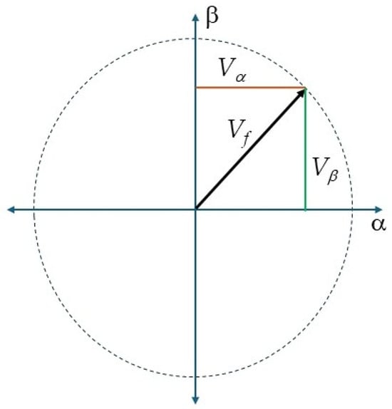
Figure 1.
Vf and its components Vα and Vβ.
Now, the Park transformation can be applied to vectors Vα and Vβ using Equation (3):
where θ is the instantaneous angle of the ω/(2π) frequency. When a synchronous reference frame is selected, that is, θ = ωt, the dq frame rotates with the same angular speed as the system frequency, and it generates constant values for Vd and Vq. If the system is balanced, Vq = Vm. Representing a three-phase system with two dc quantities has several advantages and applications, from making mathematical computations much easier to facilitating inverter-motor control.
Now, to obtain a three-phase balanced system with a specific frequency and each phase at a specific amplitude, the inverse Park and Clarke transformations are applied, and it starts by defining the values of Vs and ω to define a rotating vector VF by the following equation:
where ω is the angular frequency of the system, and Vs is the maximum voltage of the signal, which will be taken from a DC source. For the implementation of the inverse transformation using a digital system, the simplest method to generate a three-phase voltage source from a DC source is through a two-level voltage source inverter like the one shown in Figure 2.
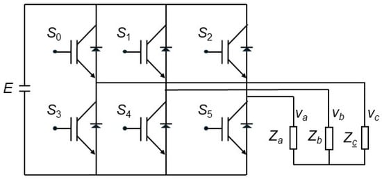
Figure 2.
Two-level voltage source inverter architecture.
The operation of the two-level voltage source inverter is performed by activating the switching elements, which usually are IGBTs or MOSFETs. They are ON when receiving a digital signal ‘1’ and OFF when the digital signal is ‘0’. Switches S0 and S3 are connected to phase a, S1 and S4 to phase b, and S3 and S5 to phase c. Because any pair of switches cannot be ON (short circuit) or OFF (no conduction) at the same time, they are operated in opposite states; therefore, the analysis that follows shows only the upper switches, S0, S1, and S2. With two possible states for each switch, there are 8 combinations: 000, 001, 010, 011, 100, 101, 110, and 111. The first and the last combinations are considered non-conductive states. The other six states are commonly arranged in a sequence where only one switch changes state at a time (this is conducted to reduce losses and high-frequency harmonics); but, in this work, the sequence is kept according to the order they appear in Figure 3 and Figure 4 because it brings the THD 17% lower (from 79.06% to 62.25%). This sequence generates the vectors represented by Equation (5).
Here, each one of the integer values (1 to 6) represents a 60° section. A graphical representation is shown in Figure 3. It can be observed that the maximum value of Vk is 2/3 Vs where Vs corresponds to the voltage value of the DC source E.
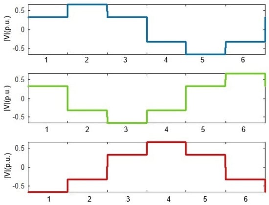
Figure 3.
Graphical representation of Equation (5) for discrete value k, phase a-blue line, phase b-green line and phase c-red line.
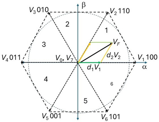
Figure 4.
Voltage space and reference vectors.
The digital values, or states, necessary to activate the power switches and generate the output waveforms in Figure 3 with the normalized voltage values are presented in Table 1.

Table 1.
Relation between switch states and voltages from Figure 3.
Table 1 and VF from Equation (4) can now be represented on a hexagon where each state corresponds to one of the six vectors, and vectors 000 and 111 are at the origin of the coordinate system, as illustrated in Figure 4.
Each vector is composed of its Vα and Vβ parts, which are obtained by their switching state through the transformation described by Equation (6).
Their angle and magnitude are derived from Equations (7) and (8):
The output voltage waveforms shown in Figure 3 are not desirable for many applications [34,35]; therefore, to generate a purer sine wave, Space Vector Pulse Width Modulation is implemented. The objective is to generate the reference vector VF from the two vectors forming a sector. Using Sector 1 as an example, V1 and V2 are the vectors to be applied. It is performed by placing inside every sector one or more PWM periods, switching between states 100 and 110 and including states 000 and 111 to fill the whole period.
The time the system stays in each state varies as the reference vector VF moves from V1 to V2 and the magnitude wanted for VF. Figure 5 shows VF and its components on V1 and V2.
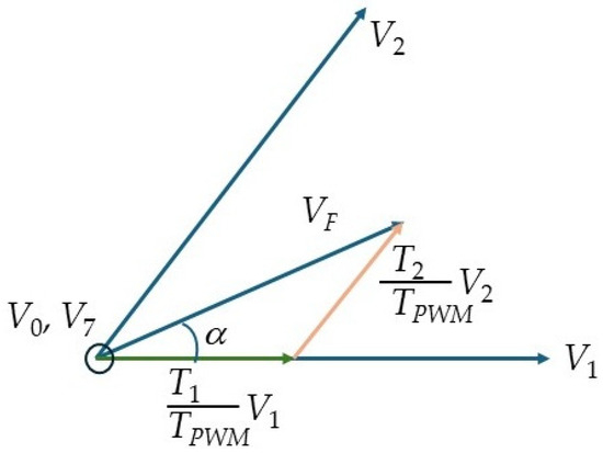
Figure 5.
Reference vector and its component vectors.
From Figure 5, if T1V1/TPWM and T2V2/TPWM are the fractions from V1 and V2 used to generate VF, Equation (9) is obtained:
where TPWM is the period of the PWM, and α is the angle of VF as it moves from V1 to V2. For the other sectors, if the reference vectors are rotated to the side vectors of each sector, the equations will be the same. The relation |VF|/Vdc is known as the modulation index. |VF| must be, as maximum, 2/3Vdc, otherwise it is called overmodulation, which is a topic not covered in this work.
Equation (9) specifies the time of each state within a PWM period. Plotting T1, T2, and T0, as α goes from 0 to 60°, and considering |VF| = 2/3(2/3Vdc) and TPWM = 1, is shown in Figure 6.
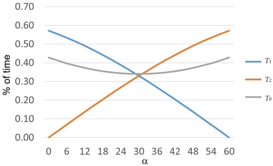
Figure 6.
T1, T2, and T0 from = 0° to 60° as percentage of a PWM period, according to Equation (9).
To reduce the computational demands for the microcontroller, T0, T1, and T2 are linearized; therefore, T1 will decrease and T2 will increase by fixed values as α goes from 0° to 60°. Therefore, instead of a look-up table requiring several jumps in the memory code, there will be only subtraction and addition operations. T0 will be left at a fixed value.
Within each sector, there could be one or more switching periods, depending on the selected PWM frequency. There are several methods to generate a switching sequence [33]. The method used in this work is the symmetrically generated SVPVM. This method is not the simplest to implement or with the lowest switching losses but generates lower total harmonic distortion. The plot for one switching period is shown in Figure 7.
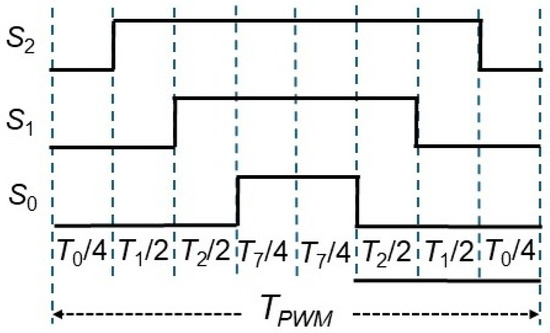
Figure 7.
Symmetrically generated SVPWM for controlling the switches of a two-level voltage source inverter.
When applying a frequency variation to a motor, there are some factors to consider, like torque and voltage, when varying the operational frequency. In this work, a constant torque is applied for frequencies below 60 Hz [36,37] and constant voltage for frequencies above 60 Hz. The constant torque is performed by reducing the voltage while reducing frequency, as seen in Figure 8. It is conducted by increasing T0 in Equation (9), inversely proportional to the frequency from 60 Hz, to the minimum of 31 Hz.
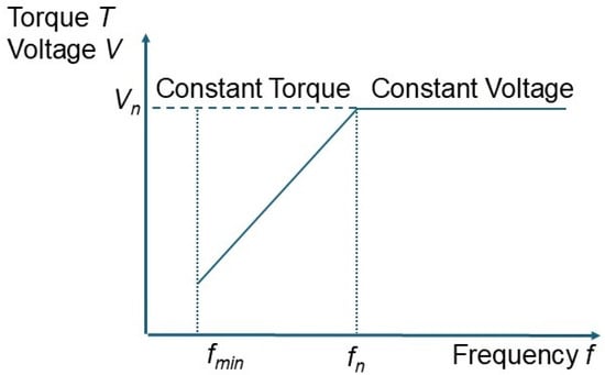
Figure 8.
Torque and voltage as function of frequency, indicating the reduction in voltage below the nominal frequency of 50–60 Hz to keep constant torque.
Now that the description of the theory and outlines of a variable-frequency motor controller have been presented, the implementation is described in the following section.
2.3. Implementation
The algorithm is implemented in an 8-bit microcontroller, the PIC18F45K50. This microcontroller has two 16-bit comparator: one is for counting the time of each sector, and the other counts the time of each switching section, i.e., T1, T2 and T0. The frequency of the microcontroller is 48 MHz, which is its maximum operational frequency. This frequency allows most of the instructions at assembler level to be executed in 0.0833 µS.
SVPWM is performed by calculating the times for T0, T1, T2, and T7. T0 and T7 are defined when selecting the output frequency. T1 and T2 vary within each sector as the reference vector moves along such sector. From Equation (8), the sine of α, from 0 to π/3, is needed. This is usually performed by a look-up table; however, it requires multiple instruction jumps so the curves in Figure 5 have been linearized as mentioned previously. With this approach, with the increment of α, T1 decreases and T2 increases, both by the same amount, making them just addition and subtraction operations.
When the user selects a new frequency, which is sent via serial communication, the program calculates the following parameters:
Time per sector in microseconds: Ts = 166666/frequency;
Time of a switching period: TPWM = Ts/N;
10% of TPWM for T0 = TPWM × 0.025 (0.1 divided by 4) when frequency ≥ 60;
T0 = TPWM × [0.025 + (60-frequency) × 0.00375] when frequency < 60;
T1 starts at its maximum value = N × (TPWM − 4 × T0)/(2(N + 1));
T2 starts at its minimum value: T2 = T1/N;
T7 includes both sides of the PWM sequence: T7 = 2 × T0;
Decrements to T1 and increments to T2: Increments = T1/N.
N is the number of switching periods according to Table 2. This is implemented to have a frequency range of switching periods between 930 and 1838. The times for T0, T1, and T2 are adjusted to finish the switching periods at the same time as each sector. T1 and T2 must have a minimum value of 6 μs to allow the program to go to the next interrupt. A modulation index (M.I.) of 0.9 is the maximum value that allows the program to finish the interrupt functions.

Table 2.
Number of PWM cycles per sector vs. frequency.
The change from one switching state to another was conducted by interrupts generated by a 16-bit comparator module. A comparator was selected because, instead of generating an interrupt on overflow, like a timer, it is performed when a counter equals a preset value, resetting the counter, and when changing the preset value, the counter already has been counting, generating precise time values for every switching state.
The flow chart of the algorithm implemented to switch states is illustrated in Figure 9.
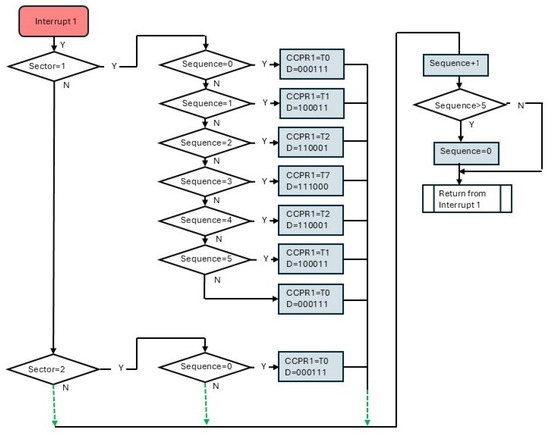
Figure 9.
Flow chart for the changing states by an interrupt.
The flow chart of the algorithm for changing sectors is illustrated in Figure 10.
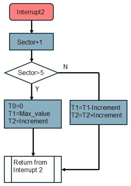
Figure 10.
Flow chart for changing sectors by an interrupt.
3. Results
The focus of this section is to demonstrate that the system generates digital signals, as presented in Figure 7, with precise times, and the frequency variation is achieved for the proposed range from 31 to 300 Hz. The first tests were performed in a virtual environment, using Proteus software, version 8.3. This environment allows visualization of the digital signals generated by the microcontroller, therefore, proving the program works correctly, changing frequency as specified by the user, and that timing is right. In Figure 11, a sample of outputs S2, S1, and S0 shows times for each period. Taking, for example, S2 (yellow line), its period takes approximately 56 μs. According to Table 2, there are five cycles per sector, and six sectors generate a cycle of the output voltage, hence, the frequency is 59.52 ≈ 60 Hz. When analyzing the signals in MATLAB/Simulink, version R2020b, it is shown that an exact value of 60 Hz is achieved.
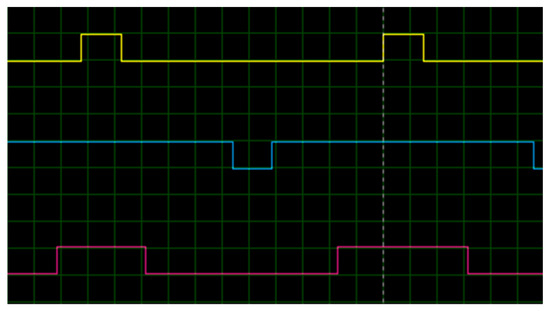
Figure 11.
Signals S2 (yellow line), S1 (blue line), and S0 (red line), for a 60 Hz voltage output (50 μs per division).
The changing values of T1 (decreasing) and T2 (increasing) are shown in Figure 12. The states included are 000, 100, 110, and 111. Because there is only a 1-bit change between vectors 100 and 110, the only signal showing variation in the plot is S1 (blue line).
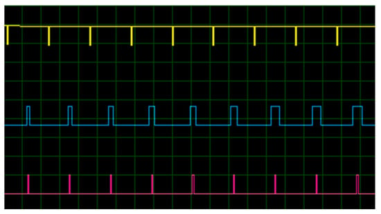
Figure 12.
Signals S2 (yellow line), S1 (blue line), and S0 (red line), for a 60 Hz voltage output (200 μs per division).
Programming and testing the microcontroller were performed on a board developed by our research team, as shown in Figure 13. This board allows for programming the microcontroller using a toolkit or through the USB port. It was designed to minimize electromagnetic interference (EMI) and to connect a Bluetooth module, LCD screen, and an SD card. A full description of the board and the Gerber files can be found in [38].
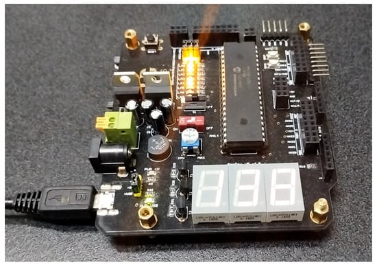
Figure 13.
The development board employed to implement the control system.
The signals, generated by the microcontroller, were captured by a data acquisition board from National Instruments, the DAQ USB-6259, for a time frame of 0.1 s. They were then fed to a virtual system in MATLAB/Simulink. These signals activated the switching MOSFETs, forming a two-level voltage source inverter, like the one presented in Figure 2. The output voltage waveforms from the voltage source inverter are shown on Figure 14.
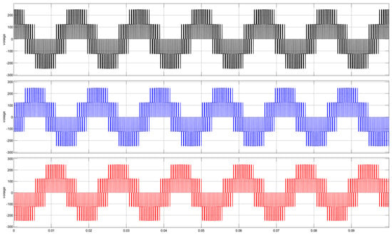
Figure 14.
Voltage waveforms at the output of the two-level voltage source inverter, phase a-black, phase b-blue and phase c-red.
The performance of the proposed system is analyzed by measuring the percentage of THD and comparing it to other systems found in the literature. The selected operating frequency to measure THD is 50 Hz; although, at 60 Hz, the value is similar. Table 3 presents the values of THD for a modulation index (M.I.) of 0.9.

Table 3.
Comparison of % THD for a modulation index of 0.9.
In [39], their system works at 50 Hz, and in [40,41], they present values at 1 and 0.8 M.I., but it shows a value at 0.9 M.I. by using the rule of proportionality. In [42], their system also works at 50 Hz. In [40,41,42], they show the performance of Sine Pulse Width Modulation, which presents a THD 21–49% above SVPWM, indicating clearly the better performance of SVPWM for reducing THD.
In this work, as was explained at the end of Section 2.2, the M.I. at 31 Hz is 0.465 and it generates a THD of 128.2.%, which is consistent with the values shown in [39,40] when they decrease the M.I.
For application specifically on induction motors, Table 4 presents works found in the literature: in [39], they do not specify the operating frequency of their proposed system and only present a system using SVPWM, and in [43,44], they compare SPWM and SVPWM using a fixed frequency.

Table 4.
Comparison of % THD for application on induction motors (M. I. of 0.9).
To demonstrate the performance of the system with an LCL filter, one was added to smooth the signals. The values for the inductors and capacitor were derived from [45], and the values calculated are L1 = 0.024 H, L2 = 0.0144 H, and C = 15.00 μF. The values of the parameters for the virtual system are presented in Table 5, and the voltage waveforms at the output of the LCL filter are shown in Figure 15.

Table 5.
Values of parameters of the virtual system.
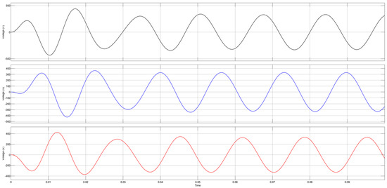
Figure 15.
LCL filter output voltage waveforms for 60 Hz, phases a, b and c are represented by black, blue and red lines, respectively.
From Figure 15, two waveform peaks are measured, and it shows that, for 60 Hz, the system generates a precise frequency, as seen in Figure 16.

Figure 16.
Voltage waveform measurement at 60 Hz (horizontal axis in seconds and vertical axis in volts).
Next, the system frequency is changed to operate at 31 Hz to observe its behavior as it is shown in Figure 17. The frequency operates at 30.97 Hz, a deviation of 0.097%. The output phase voltage is reduced to 119 V to keep a constant torque as was expected.
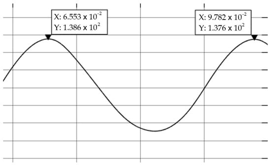
Figure 17.
Voltage waveform measurement at 31 Hz (horizontal axis in seconds and vertical axis in volts).
Finally, the system frequency is changed to operate at 300 Hz, and its voltage waveforms are shown in Figure 18. The frequency operates at 299.4 Hz, with a deviation of 0.19%. This is the maximum deviation from the nominal frequency in the entire range. The output pick phase voltage is 216.7 V.
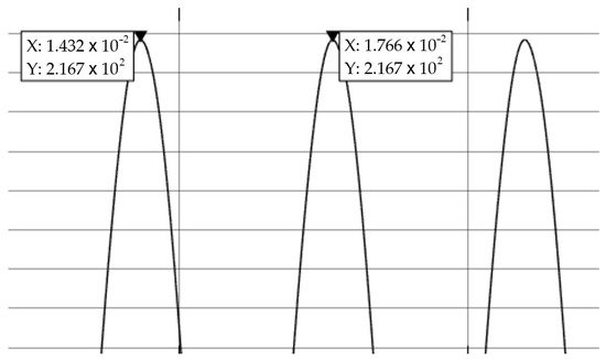
Figure 18.
Voltage waveform measurement at 300 Hz (horizontal axis in seconds and vertical axis in volts).
The voltage waveforms for 60 Hz, shown in Figure 16, have a THD of 2.43%; for 31 Hz, observed in Figure 17, the THD was 4.02%; and for 300 Hz, presented in Figure 18, the THD was 0.43%. Table 6 presents THD values across various frequencies along the entire range the system can generate. These values have been obtained with a lineal load of 1.3 kW. For a non-lineal load with 500 var added to the active power, the THD for 60 Hz increases to 3.68%, showing the system performance. The IEEE 519–2014 Standard [46] recommends a maximum voltage THD below 8% for systems with a voltage of 1000 volts or less; therefore, the generated system voltage output waveforms adhere to this recommendation, showing the attenuation performance of the filter.

Table 6.
THD after the LCL filter for different frequencies.
According to [47], the resonance frequency of LCL filters is given by
where L = L1 + L2, and r = L1/L. The resonance frequency for the LCL filter is 433.16 Hz, therefore, there is no damping requirement.
Finally, a virtual test bench was implemented in MATLAB/Simulink to evaluate the system using an induction motor with parameters identical to an industrial motor from GE, model number 5KAF145SAA202A, catalogue number M9301. The parameters of the motor are described in Table 7. The system worked at a frequency of 60 Hz. Figure 19 shows the rotor speed and current of phase a with 100% load. The behavior of the motor demonstrates that the system can operate an induction motor properly.

Table 7.
Induction motor parameters.
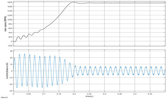
Figure 19.
Rotor speed and current of phase from motor described in Table 6.
4. Conclusions
This paper presented a functional control system for a variable-frequency driver. The system was implemented in an 8-bit microcontroller programmed using language C. The aim was to offer a motor control system to generate the switching signals of a two-level inverter with variable frequency in the range of 31 to 300 Hz. The control includes a voltage reduction, inversely proportional to the frequency reduction for frequencies below 60 Hz to maintain constant torque. The number of switching periods decreased from nine to one with an increase in frequency, as is shown in Table 2, to enable the use of one LCL filter for the entire range of frequencies the system can generate. Two 16-bit comparators from the microcontroller were used for counting every sector and PWM cycles, obtaining a high-precision output frequency. A change in the switching sequence, following the order vectors presented in Figure 4, generated a THD reduction of 16.81%, and doing so allows this system to be used in industrial applications because it obtains a performance comparable to systems developed on high-level systems like FPGAs and DSPs. Besides, it offers power electronics students the opportunity to follow the theory for SVPWM, acquire the description of the implementation, and download the code to program a microcontroller from the PIC18 family with only having to adjust the configuration lines. Or they can adapt the C code to any microcontroller that can be programmed with language C.
Author Contributions
Conceptualization, G.C.-V.; methodology, G.C.-V.; software, G.C.-V. and F.J.M.-V.; validation, G.C.-V. and A.B.; formal analysis, G.C.-V. and A.B.; investigation, G.C.-V. and F.J.M.-V.; resources, A.B.; data curation, G.C.-V.; writing—original draft preparation, G.C.-V. and F.J.M.-V.; writing—review and editing, G.C.-V. and A.B.; visualization, G.C.-V. All authors have read and agreed to the published version of the manuscript.
Funding
This research received no external funding.
Data Availability Statement
The original contributions presented in this study are included in the article. Further inquiries can be directed to the corresponding author.
Conflicts of Interest
The authors declare no conflicts of interest.
References
- Bose, B.K. The past, present, and future of power electronics [Guest Introduction]. IEEE Ind. Electron. Mag. 2009, 3, 7–11. [Google Scholar] [CrossRef]
- Wu, H.; Hu, X. Reserch of SVPWM Variable Frequency Speed Regulation System Based on TMS320LF2407A. In Proceedings of the 2008 International Symposium on Intelligent Information Technology Application Workshops, Shanghai, China, 21–22 December 2008; pp. 1041–1044. [Google Scholar] [CrossRef]
- Sandulescu, P.; Idkhajine, L.; Cense, S.; Colas, F.; Kestelyn, X.; Semail, E.; Bruyere, A. FPGA implementation of a general Space Vector approach on a 6-leg voltage source inverter. In Proceedings of the IECON 2011-37th Annual Conference of the IEEE Industrial Electronics Society, Melbourne, VIC, Australia, 7–10 November 2011; pp. 3482–3487. [Google Scholar] [CrossRef]
- Madasamy, P.; Pongiannan, R.K.; Ravichandran, S.; Padmanaban, S.; Chokkalingam, B.; Hossain, E.; Adedayo, Y. A Simple Multilevel Space Vector Modulation Technique and MATLAB System Generator Built FPGA Implementation for Three-Level Neutral-Point Clamped Inverter. Energies 2019, 12, 4332. [Google Scholar] [CrossRef]
- Sapkota, Y. Design of FPGA-Based PWM Techniques for Inverters. Master’s Thesis, Youngstown State University, Youngstown, OH, USA, December 2023. [Google Scholar]
- Waleed, U.; Waseem, M.; Shaukat, H.; Ijaz, A.; Almalaq, A.; Mohamed, M.A. An Efficient FPGA Based Scalar V/f Control Mechanism of Three Phase Induction Motor for Electric Vehicles. In Proceedings of the 2021 31st Australasian Universities Power Engineering Conference (AUPEC), Perth, Australia, 26–30 September 2021; pp. 1–6. [Google Scholar] [CrossRef]
- Liyanage, A.; Nagrial, M.; Hellany, A.; Rizk, J. Speed Control of Induction Motors Using V/f Control Method. In Proceedings of the 2022 International Conference on Electrical and Computing Technologies and Applications (ICECTA), Ras Al Khaimah, United Arab Emirates, 23–25 November 2022; pp. 424–429. [Google Scholar] [CrossRef]
- Wibowo, P.S.; Riyadi, S. SPWM Volt/Hz Based Speed Control of Induction Motor. In Proceedings of the 2019 International Seminar on Application for Technology of Information and Communication (iSemantic), Semarang, Indonesia, 21–22 September 2019; pp. 482–486. [Google Scholar] [CrossRef]
- Sieklucki, G.; Sobieraj, S.; Gromba, J.; Necula, R.-E. Analysis and Approximation of THD and Torque Ripple of Induction Motor for SVPWM Control of VSI. Energies 2023, 16, 4628. [Google Scholar] [CrossRef]
- Tuknyasrirut, S.; Srilad, S.; Suksri, T. Comparison Power Quality of the Voltage Source Inverter type SVPWM and SPWM Technique for Induction motor Drive. In Proceedings of the SICE Annual Conference 2008, Tokyo, Japan, 20–22 August 2008; pp. 241–246. [Google Scholar]
- Ali, A.K.; Ercelebi, E. Simulation and Study of SVPWM Inverter for (VFD) Applications. Int. J. Electron. Electr. Eng. 2017, 5, 158–170. [Google Scholar] [CrossRef][Green Version]
- Patel, J.J.; Kubavat, A.M.; Jhala, M.B. Speed Control of a Three Phase Induction Motor Using PWM Inverter. Int. J. Eng. Dev. Res. 2014, 2, 503–507. [Google Scholar]
- Dems, M.; Komeza, K.; Szulakowski, J.; Kubiak, W. Increase the Efficiency of an Induction Motor Feed from Inverter for Low Frequencies by Combining Design and Control Improvements. Energies 2022, 15, 530. [Google Scholar] [CrossRef]
- Doan, N.S.; Tsvetkov, A.N.; Nguyen, T.H. Study and implementation of space vector pulse width modulation inverter on an Arduino. E3S Web Conf. 2021, 288, 01059. [Google Scholar] [CrossRef]
- Badran, M.A.A.; Tahir, A.M.; Faris, W.F. Digital Implementation of Space Vector Pulse Width Modulation Technique Using 8-bit Microcontroller. World Appl. Sci. J. 2013, 21, 21–28. [Google Scholar]
- Vivek, G.; Biswas, J.; Muthavarapu, A.K.; Nair, M.D.; Barai, M. Optimised Design and Implementation of SVPWM Switching sequences for Five level VSI. In Proceedings of the 2018 IEEE International Conference on Power Electronics, Drives and Energy Systems (PEDES), Chennai, India, 18–21 December 2018; pp. 1–6. [Google Scholar] [CrossRef]
- AVR435: BLDC/BLAC Motor Control Using a Sinus Modulated PWM Algorithm. ATMEL Application Note. Available online: https://ww1.microchip.com/downloads/en/Appnotes/doc7671.pdf (accessed on 20 February 2025).
- AN2154: Space Vector Modulation Using 8-bit ST7MC Microcontroller and ST7MC-KIT/BLDC Starter Kit. STMicroelectronics Application Note. Available online: https://www.st.com/resource/en/application_note/cd00055518-space-vector-modulation-using-8bit-st7mc-microcontroller-and-st7mckitbldc-starter-kit-stmicroelectronics.pdf (accessed on 23 February 2025).
- AP0803620: Optimized Space Vector Modulation and Over-Modulation with the XC866. Available online: https://www.infineon.com/cms/en/product/gated-document/optimized-space-vectormodulation-and-over-modulationwith-the-xc866-description-db3a304412b407950112b4199b7b28b3/ (accessed on 23 February 2025).
- Midhun, G.; Sandhya, P. Hardware Implementation of a Dual Two-Level Inverter with SVPWM Using Pic Microcontroller. J. Res. Eng. Appl. Sci. 2016, 4, 185–190. [Google Scholar]
- Datta, S.; Chandra, A.; Chowdhuri, S. Design and development of an 8 bit microcontroller based space vector PWM inverter fed volt/Hz induction motor drive. In Proceedings of the 2016 2nd International Conference on Control, Instrumentation, Energy & Communication (CIEC), Kolkata, India, 28–30 January 2016; pp. 353–357. [Google Scholar] [CrossRef]
- Hamim, M.Z.; Salimin, S.; Bakar, A.A. Analysis of Variable Frequency Drive for Induction Motor using Matlab Software. J. Adv. Res. Appl. Mech. 2024, 116, 117–129. [Google Scholar] [CrossRef]
- Available online: https://www.bluebayautomation.com/blog/motion-control-gearing-mechanics-12/variable-frequency-drive-usage-in-industrial-applications-71 (accessed on 14 April 2025).
- Available online: https://www.plctechnician.com/news-blog/variable-frequency-drives-basics-and-common-applications-vfds (accessed on 15 April 2025).
- Sauer, B.J.; Brady, P.A. Application of AC Induction Motors with Variable Frequency Drives. In Proceedings of the 2009 IEEE Cement Industry Technical Conference Record, Palm Springs, CA, USA, 29 May–5 June 2009; pp. 1–10. [Google Scholar] [CrossRef]
- PowerFlex Low Voltage AC Drives. Available online: https://literature.rockwellautomation.com/idc/groups/literature/documents/br/pflex-br008_-en-p.pdf (accessed on 18 April 2025).
- FRENIC-Mini (C2) Series User’s Manual. Fuji Electric Co., Ltd.. Available online: https://americas.fujielectric.com/wp-content/uploads/2016/07/FEA-ACDR-BR-105a_web.pdf (accessed on 25 May 2025).
- Altivar Process ATV600. Available online: https://download.schneider-electric.com/files?p_Doc_Ref=EAV64318&p_enDocType=User+guide&p_File_Name=ATV600_Programming_Manual_EN_EAV64318_12.pdf (accessed on 16 April 2025).
- Zellouma, D.; Bekakra, Y.; Benbouhenni, H. Field-oriented control based on parallel proportional–integral controllers of induction motor drive. Energy Rep. 2023, 9, 4846–4860. [Google Scholar] [CrossRef]
- Sengamalai, U.; Anbazhagan, G.; Thamizh Thentral, T.M.; Vishnuram, P.; Khurshaid, T.; Kamel, S. Three Phase Induction Motor Drive: A Systematic Review on Dynamic Modeling, Parameter Estimation, and Control Schemes. Energies 2022, 15, 8260. [Google Scholar] [CrossRef]
- Mencou, S.; Yakhlef, M.B.; Tazi, E.B. Advanced Torque and Speed Control Techniques for Induction Motor Drives: A Review. In Proceedings of the 2022 2nd International Conference on Innovative Research in Applied Science, Engineering and Technology (IRASET), Meknes, Morocco, 3–4 March 2022; pp. 1–9. [Google Scholar] [CrossRef]
- Kubeitari, M.; Alhusayn, A.; Alnahar, M. Space Vector PWM Simulation for Three Phase DC/AC Inverter. Int. J. Electr. Comput. Eng. 2012, 6, 1402–1407. [Google Scholar] [CrossRef]
- Neacsu, D.O. Space Vector Modulation-An Introduction. In Proceedings of the Tutorial at IECON2001, 27th Annual Conference of IEEE, Denver, CO, USA, 29 November–2 December 2001; pp. 1538–1592. [Google Scholar]
- Patin, N. DC/AC Converters. In Power Electronics Applied to Industrial Systems and Transports 2, 1st ed.; ISTE Press–Elsevier: London, UK, 2015; pp. 36–100. [Google Scholar]
- Jaen-Cuellar, A.Y.; Elvira-Ortiz, D.A.; Resendiz-Ochoa, E.; Saucedo-Dorantes, J.J. Analysis of the Effects Produced by Pure Sine and Modified Sine Inverters in an Induction Motor. In New Trends in Electric Machines-Technology and Applications; IntechOpen: London, UK, 2023. [Google Scholar] [CrossRef]
- Evon, S.T.; Oakes, B. Variable frequency drive principles and practices (above NEMA) AC motors for variable frequency application. In Proceedings of the Conference Record of 1999 Annual Pulp and Paper Industry Technical Conference (Cat. No.99CH36338), Seattle, WA, USA, 21–25 June 1999; pp. 94–108. [Google Scholar] [CrossRef]
- Song-Manguelle, J.; Ekemb, G.; Mon-Nzongo, D.L.; Jin, T.; Doumbia, M.L. A Theoretical Analysis of Pulsating Torque Components in AC Machines with Variable Frequency Drives and Dynamic Mechanical Loads. IEEE Trans. Ind. Electron. 2018, 65, 9311–9324. [Google Scholar] [CrossRef]
- Available online: https://sites.google.com/view/beedev (accessed on 25 May 2025).
- Balasubramanian, G.; Chandrasekar, P.; Alexandar, S.A. Variable Frequency Drive operated Air Blower in Air Handling Unit of Heating, Ventilation and Air Conditioning Systems. In Proceedings of the 2022 IEEE Delhi Section Conference (DELCON), New Delhi, India, 11–13 February 2022; pp. 1–7. [Google Scholar] [CrossRef]
- Kumar, K.V.; Michael, P.A.; John, J.P.; Kumar, S.S. Simulation and Comparison of Spwm and Svpwm Control for Three Phase Inverter. Arpn J. Eng. Appl. Sci. 2010, 5, 61–74. [Google Scholar]
- Islam, M.T.; Ayon, S.I. Performance Analysis of Three-Phase Inverter for Minimizing Total Harmonic Distortion Using Space Vector Pulse Width Modulation Technique. In Proceedings of the 2020 23rd International Conference on Computer and Information Technology (ICCIT), Dhaka, Bangladesh, 19–21 December 2020; pp. 1–4. [Google Scholar] [CrossRef]
- Sharma, R.; Goyal, D.K.; Singh, H. Analysis of Space Vector PWM for Three Phase Inverter and Comparison with SPWM. Int. J. Adv. Res. EEIE 2016, 5, 533–540. [Google Scholar]
- Hussein, T.A.; Mohamed, L.A. Detailed Simulink Implementation for Induction Motor Control Based on Space Vector Pulse Width Modulation SVPWM. Indones. J. Electr. Eng. Comput. Sci. 2021, 22, 1251–1262. [Google Scholar] [CrossRef]
- Ramarao, G.; Karunakar, S.; Kumari, D.V.; Adithya, M.V.; Gnaneswar, D. Simulation and Comparative Analysis Between Svpwm and Spwm Techniques for Speed Control of 3 Phase Induction Motor. In Proceedings of the 2024 IEEE International Conference on Smart Power Control and Renewable Energy (ICSPCRE), Rourkela, India, 19–21 July 2024; pp. 1–6. [Google Scholar] [CrossRef]
- Hasan, S.; Suherman; Saragi, D.P.; Siregar, Y.; Al-Akaidi, M. The LCL Filter Design for Three Phase DC-AC Voltage Converter. J. Phys. Conf. Ser. 2021, 1783, 012067. [Google Scholar] [CrossRef]
- IEEE. IEEE Recommended Practice and Requirements for Harmonic Control in Electric Power Systems (IEEE 519-2014). 2014. Available online: https://ieeexplore.ieee.org/xpl/RecentIssue.jsp?punumber=6826457 (accessed on 23 March 2025).
- Kim, Y.-J.; Kim, H. Optimal Design of LCL Filter in Grid-Connected Inverters. IET Power Electron. 2019, 12, 1774–1782. [Google Scholar] [CrossRef]
Disclaimer/Publisher’s Note: The statements, opinions and data contained in all publications are solely those of the individual author(s) and contributor(s) and not of MDPI and/or the editor(s). MDPI and/or the editor(s) disclaim responsibility for any injury to people or property resulting from any ideas, methods, instructions or products referred to in the content. |
© 2025 by the authors. Licensee MDPI, Basel, Switzerland. This article is an open access article distributed under the terms and conditions of the Creative Commons Attribution (CC BY) license (https://creativecommons.org/licenses/by/4.0/).