Article

Analysis of the Mechanical Response Characteristics of a Suction Pile Wellhead Pre-Tilted Conductor for Gas Hydrate Pilot Production

1
State Key Laboratory of Offshore Natural Gas Hydrate, CNOOC Research Institute Company Limited, Beijing 100028, China
2
Beijing Huairou Laboratory, Beijing 101400, China
*
Author to whom correspondence should be addressed.
Processes 2025, 13(6), 1867; https://doi.org/10.3390/pr13061867
Submission received: 24 March 2025 / Revised: 15 May 2025 / Accepted: 4 June 2025 / Published: 13 June 2025

Abstract

The use of suction pile wellheads with pre-tilted conductors is expected to help overcome the challenge of high tilting difficulty in offshore gas hydrate extraction. However, structural design and safety control technologies still lack theoretical guidance. In this study, based on Novak’s plane-strain assumption, the potential effects of the pre-tilted conductor on the pipe–soil interaction were considered, along with the influence of working loads and conductor structural parameters. A dynamic vibration model was established to describe the interaction between the suction pile wellhead’s pre-tilted conductor and the surrounding soil, and an analytical expression for the impedance at the conductor’s bottom was derived. Subsequently, parameter analysis was performed using a Python-based computational program (version 3.12.5) to investigate the mechanical response characteristics of the conductor under varying conductor sizes, total lengths, pre-tilted angles, external load magnitudes, and frequency. The results showed that increasing the conductor outer diameter from 32’ to 40’ significantly reduced end displacement by up to 91.24% and bending moments by 30.22%, while shear load decreased by 31.45%, providing important insights for the design of pre-tilted conductors in gas hydrate pilot production. The findings provide theoretical support for the optimal design and safety control technologies of suction pile wellhead pre-tilted conductors.

1. Introduction

From October 2019 to April 2020, China conducted the second gas hydrate pilot production in the Shenhu area of the South China Sea [1]. During the pilot, suction pile and jetting 36-inch conductor construction technology was used, which verified the application prospects of suction pile technology in offshore gas hydrate extraction. However, several issues were exposed during this pilot, including shallow hydrate reservoir depth, high tilting difficulty, and high dog-leg severity in the riser pipe. To address these problems, researchers have proposed the use of pre-fabricated inclined suction pile conductors at the wellhead [2], which involves using conductors with adjustable tilt angles at the suction pile wellhead. The maximum pre-tilted angle can reach 15°, which significantly reduces the dog-leg severity in the inclination section. However, compared to conventional straight conductors, these pre-tilted conductors experience more complex stress states during operation, leading to a higher risk of failure. Moreover, research on their structural design and safety control technology still lacks sufficient theoretical foundation. Therefore, this paper conducts a systematic analysis of the mechanical response characteristics of pre-tilted conductors at suction pile wellheads, aiming to establish a computational method for evaluating the working performance of pre-tilted conductors and provide theoretical support for their structural design and safety control technologies.
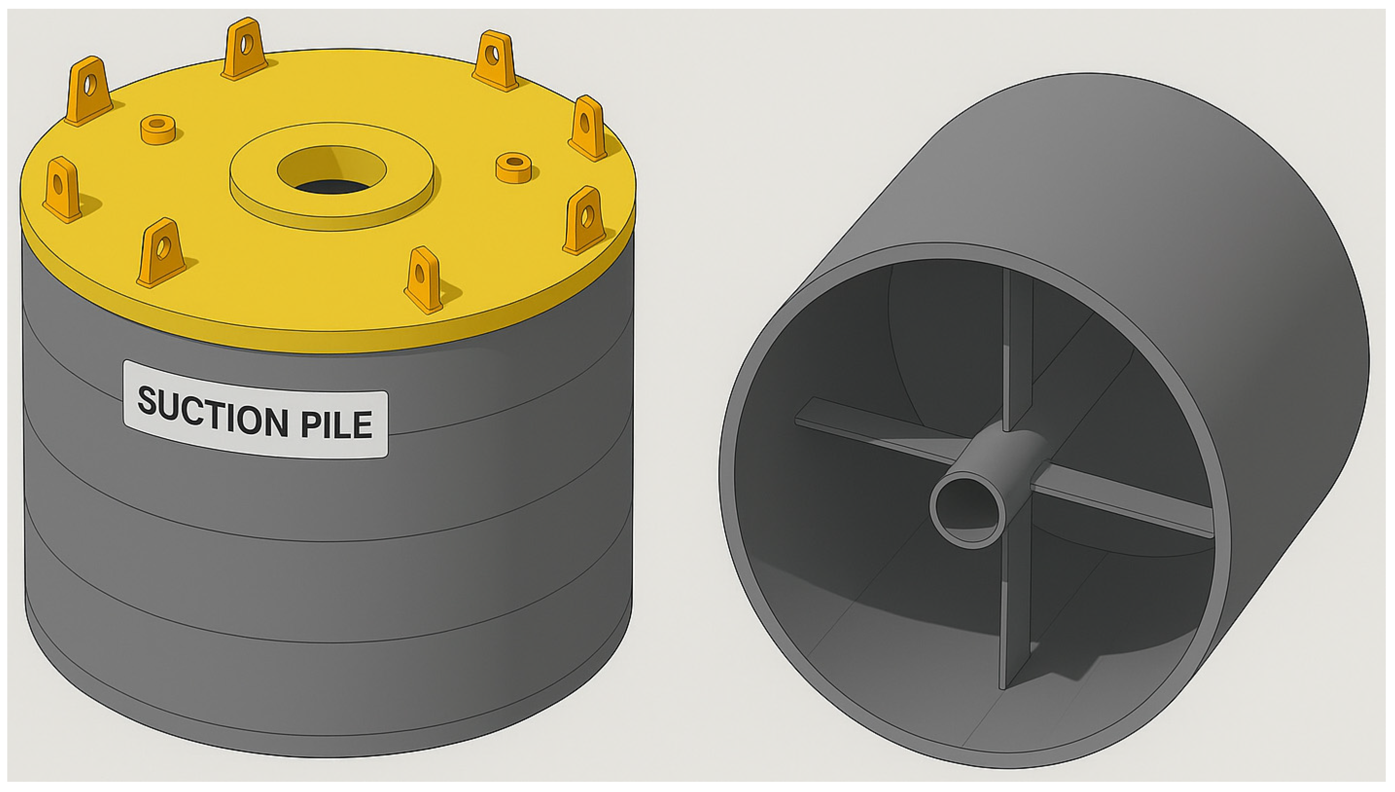
The single suction pile is primarily constructed from a steel suction pile with a closed top and an open bottom, resembling an inverted barrel. The suction pile wellhead device is a specially designed structure for suction piles, as shown in Figure 1. As a mooring technology, the application of suction piles in deep water has already matured internationally. Companies such as Eni Norway, Neodrill AS, and Det Norske Oljeselskap ASA [3] have each developed their respective suction pile wellhead technologies. In addition, during China’s 2020 offshore gas hydrate pilot [1], suction pile technology was used for well construction, meeting the engineering requirements of the trial production. Furthermore, Wang Lei and colleagues from Sinopec [2] proposed a suction pile conductor device with a pre-tilted function in their invention patent. This device allows for a pre-tilted angle of up to 15°, effectively reducing dog-leg severity to 6° per 30 m.
In recent decades, numerous scholars have made significant achievements in the study of the dynamic interaction between piles and surrounding soil. Based on different modeling approaches to pile–soil interactions, three main models have been developed and proposed: the Winkler foundation model, Novak’s plane-strain model, and the three-dimensional continuous medium model [4]. Among these, the Winkler foundation model is widely used due to its structural simplicity and computational efficiency. It can simulate pile–soil dynamic interactions under small deformation conditions and capture nonlinear behaviors such as slippage and detachment between the pile and surrounding soil under large deformations. However, this model neglects the continuity of stress–strain in the foundation soil and is highly dependent on experimental data, which limits its applicability. The three-dimensional continuous medium model places more emphasis on the longitudinal continuity of the soil and can accurately reflect the three-dimensional wave effects in the soil. However, its complex analytical solutions and potential convergence issues make it challenging for engineering applications. The Novak’s plane-strain model, developed on the basis of the Winkler foundation model, offers a balance between computational efficiency and physical accuracy. It effectively captures radiation damping and radial wave effects, making it widely applicable for time–frequency domain analysis of pile foundations under dynamic loading conditions.
The Novak’s plane-strain model was first proposed by Novak et al. [5], who equated the soil surrounding the pile to a series of independent infinitely thin layers, ignoring the longitudinal interactions between these layers. This approach simplifies the plane-strain representation of the pile–soil system, allowing for an analytical solution of the soil’s complex stiffness. As a result, the Novak model provides an alternative to the Winkler foundation model by offering a more accurate representation of soil damping and stiffness effects.
In recent studies, Liu Linchao et al. [6,7,8,9] investigated the horizontal dynamic impedance of a single pile in a viscoelastic soil layer. Based on Novak’s plane-strain model, they extended it to saturated soil media, analyzing the vertical and horizontal vibration characteristics of a single pile in saturated soil and the vertical and horizontal dynamic interactions of pile groups. Liu [6] analyzed longitudinal and transverse vibrations of single and group piles in saturated soil using porous media theory. Liu and Yang [7] derived horizontal displacement attenuation functions and expressions for stiffness and damping via a plane-strain model and wave propagation theory. Liu and Yan [8] incorporated fractional derivatives and viscoelastic theories to model horizontal vibration, showing impedance degeneration to classical cases. Gao, Liu, and Yan [9] treated surrounding soil as a viscoelastic medium with fractional properties, confirming similar degeneration for pile groups. Wu Wenbing et al. [10,11] employed a complex stiffness transfer method using a multi-layered plane-strain model and solved the dynamic impedance of the longitudinal vibration of wedge piles in layered soil using the Laplace transform and impedance function transfer methods. Yang Dongying and Ding Haiping [12] established a virtual pile–soil model based on the plane-strain model and derived the shear complex stiffness of the soil surrounding the pile through the multi-layered complex stiffness transfer method. They then obtained both frequency-domain and time-domain analytical solutions for the pile head based on boundary continuity conditions. Han Hongxia et al. [13] used the Fourier expansion method to derive the analytical expression for the horizontal dynamic impedance of the soil around the pile and derived the analytical solution for the horizontal impedance of a single pile. Cui Chunyi et al. [14,15,16], based on the plane-strain model and the viscous damping soil model, investigated the effects of radial heterogeneity in the surrounding soil and the impact of longitudinal layering on the longitudinal vibration behavior of piles in heterogeneous viscous damping soil. Cui et al. [14] modeled pipe piles as elastic bodies in axisymmetric viscous soil, assessing structural and soil disturbance effects. Cui et al. [15] introduced a complex stiffness transfer model for radially layered soil, analyzing radial heterogeneity via parametric studies. Cui et al. [16] proposed a multi-ring plane-strain model, deriving an analytical solution for pile-head dynamic impedance. Subsequently, Liang et al. [17,18,19,20] employed the potential function method and the separation of variables method to study the top horizontal impedance of piles with embedded soil plugs, deriving their analytical solutions. Liang et al. [17] modeled longitudinal vibration in bidirectionally heterogeneous soil, considering lateral inertia and soil disturbance. Meng et al. [18] applied dynamic Winkler and virtual soil–pile models to floating piles, evaluating incomplete bonding effects. Cui et al. [19] developed a 3D continuum model for large-diameter pipe piles in radially heterogeneous soil, accounting for vertical wave effects. Liang et al. [20] addressed soil plug effects in partially embedded piles, deriving horizontal impedance solutions in layered viscoelastic soil. Wang Kuihua et al. [21], combining the plane-strain model with Laplace transform and impedance transfer methods, derived the dynamic response analytical solution at the top of a wedge pile and validated their computational results through model experiments. Hu Anfeng et al. [22] used the separation of variables method and the operator decomposition method to derive the analytical solution for the top impedance of wedge piles.
In the above studies, extensive research has been conducted on various pile–soil coupled mechanical behaviors based on Novak’s plane-strain assumption. However, in gas hydrate pilot production using suction pile wellheads with pre-tilted conductors, the presence of the pre-tilted angle introduces longitudinal compressive deformation and friction between soil layers, leading to different mechanical relationship between the pipe and the soil. Additionally, external loads primarily act at the conductor’s bottom. Therefore, existing pile–soil coupling mechanical models are not applicable to suction pile wellheads with pre-tilted conductors.
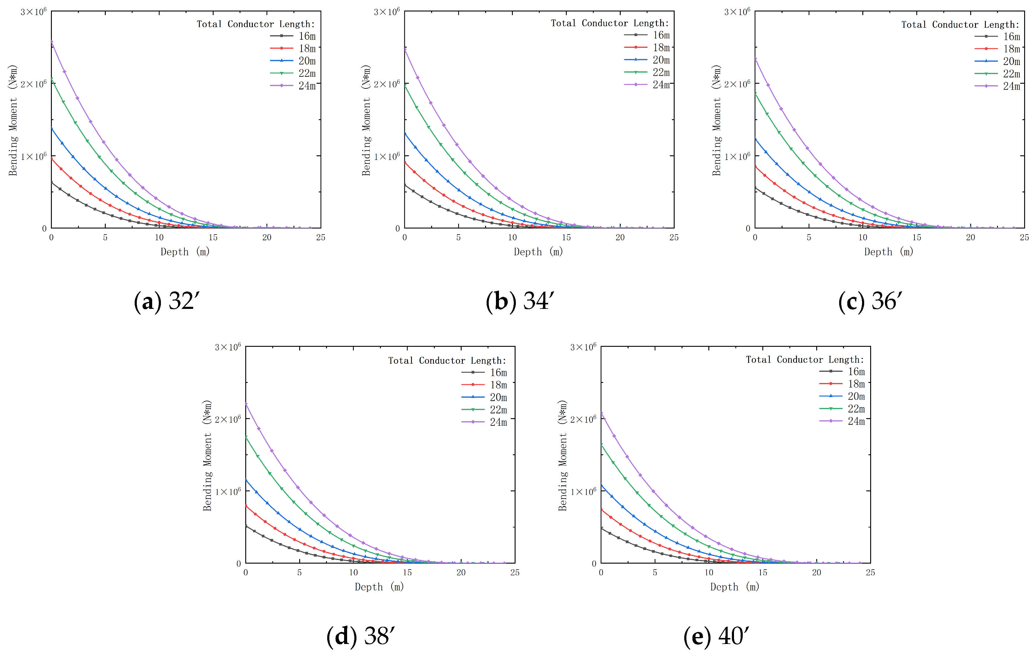
This paper focuses on the structural and operational characteristics of suction pile wellheads with pre-tilted conductors in offshore gas hydrate extraction. Based on Novak’s plane-strain assumption, a vibration control model is established, and multiple mechanical response characteristics of the conductor are derived. A Python numerical calculation program is developed to conduct parameterized studies on the dynamic impact of conductor geometry (e.g., outer diameter, pre-tilted angle) and operating load parameters on the conductor’s mechanical response. This study reveals the deformation characteristics of pre-tilted conductors under complex marine conditions and provides an analytical tool and theoretical foundation for the optimal design of offshore hydrate extraction equipment.

2. Methods

2.1. Model

This study investigates the suction pile wellhead applied in the 2020 offshore gas hydrate pilot production [1], along with the pre-tilted conductor suction pile wellhead proposed by Wang Lei et al. [2]. However, compared with the vertical (straight) conductor configuration, the pre-tilted conductor introduces changes in the force distribution due to geometric inclination. For instance, it is subject to higher bending moments, and its deformation leads to compressive interaction with the surrounding soil, affecting the deformation behavior of the conductor. Therefore, based on the mechanical model for the straight conductor, modifications are necessary to account for the geometric and force characteristics of the pre-tilted conductor.
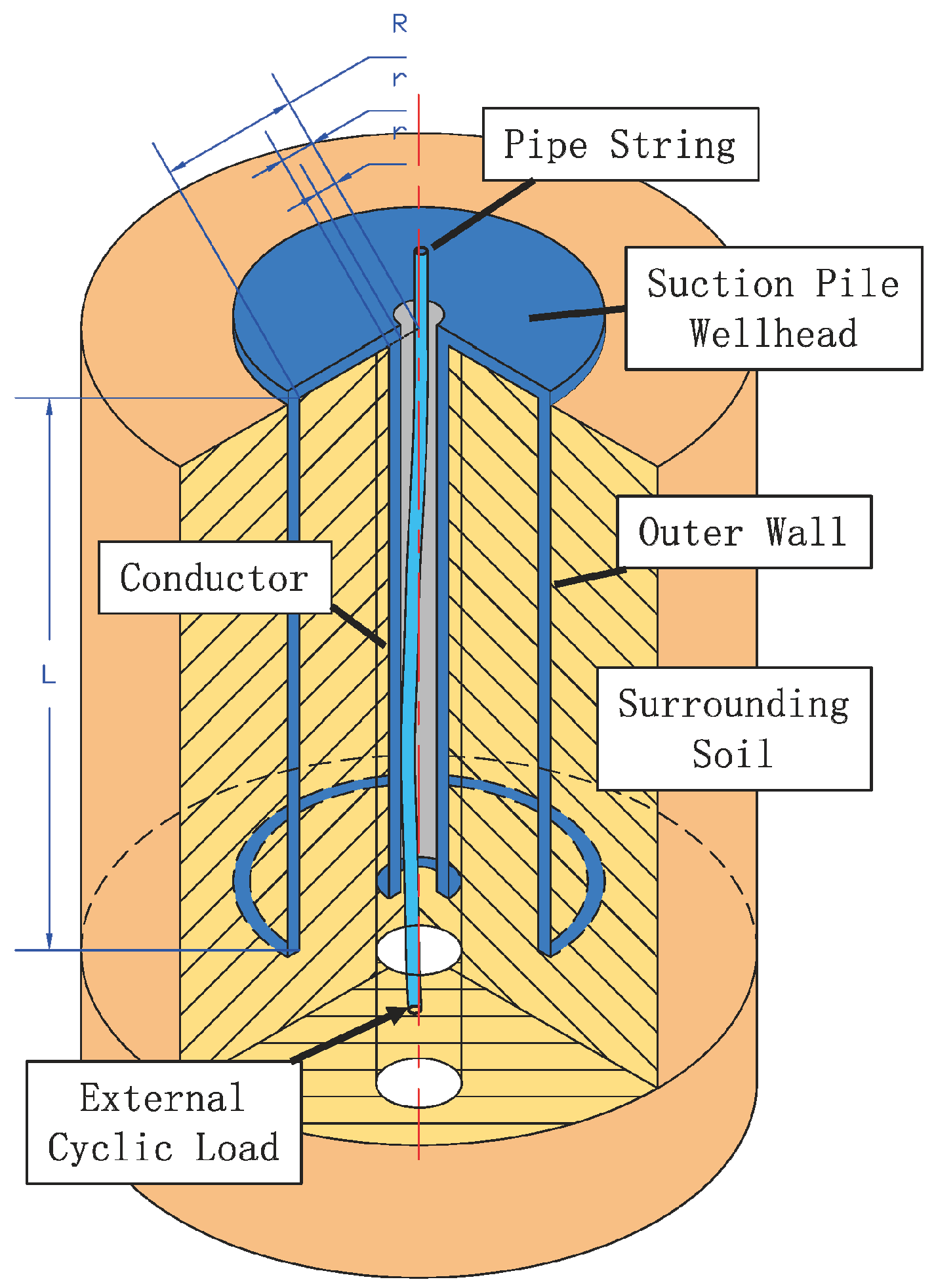
In the simplified physical model under the straight conductor case (
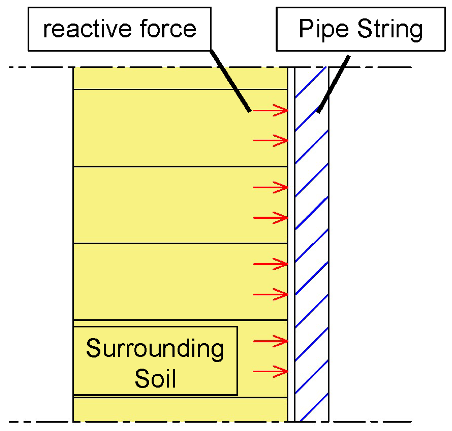
Figure 2), based on Novak’s plane-strain assumption, the soil surrounding the conductor is simplified as a series of infinitely thin, parallel soil layers, with friction and compression between layers ignored. The interaction and contact between the conductor and the surrounding soil are illustrated in Figure 3. The mechanical model is simplified and assumed as follows [4,23]:
(1)
The suction pile conductor is simplified as an Euler–Bernoulli beam, with horizontal shear strain of the conductor ignored. The top end of the conductor, i.e., the wellhead, is considered as a fixed boundary.
(2)
The soil layers in contact with the conductor are assumed to be homogeneous, isotropic, and viscoelastic, following Novak’s plane-strain assumption.
(3)
The interface between the conductor and the soil is assumed to be in perfect contact, with no slip. The vibration type is considered to involve small deformations, with vertical displacements of the soil ignored.
Based on these assumptions and considering the viscoelastic properties of the materials and dynamic loads, the governing equation for the soil in each sub-layer can be obtained [20].
λ i + 2 μ i 1 r r u r i r + u θ i θ e i ω t r 2 μ i 1 2 r r u θ i r + u r i θ e i ω t r θ = ρ i 2 t 2 u r i e i ω t
λ i + 2 μ i 1 r r u r i r + u θ i θ e i ω t r θ 2 μ i 1 2 r r u θ i r + u r i θ e i ω t r = ρ i 2 t 2 u θ i e i ω t
In this context, λ i and μ i represent the Lamé constants of the i -th soil sub-layer, which describe the elastic properties of the soil. These parameters are given by λ i = 2 v i μ i 1 2 v i and μ i = G i 1 + 2 i ξ i , where v i , G i , and ξ i are the Poisson’s ratio, shear modulus, and damping ratio of the i -th soil sub-layer, respectively. The parameter r denotes the outer diameter of the conductor, while u r i and u θ i represent the radial and circumferential displacements of the i -th soil sub-layer. Additionally, ρ i denotes the density of the i -th soil sub-layer.
Considering the elastic deformation of the conductor, inertial forces, and soil damping, the horizontal vibration control equation [20] for the suction pile conductor in the i -th sub-layer can be expressed as:
E p I p 4 u p i e i ω t z 4 + m p i 2 u p i e i ω t t 2 + f l i u p i e i ω t = 0
where u p i represents the horizontal displacement of the conductor in the i -th sub-layer, E p is the shear modulus of the conductor, and I p is the moment of inertia of the conductor cross-section, given by I p = 1 4 π r o u t 4 r i n 4 . The parameter m p i represents the mass per unit length of the conductor in the i -th sub-layer, given by m p i = ρ p π r o u t 4 r i n 4 , and f l i denotes the amplitude of the horizontal force exerted by the surrounding soil on the conductor in the i -th sub-layer.
To establish the mechanical model for the pre-tilted conductor, the straight conductor in the physical model shown in Figure 2 is replaced with a pre-tilted conductor, resulting in the updated physical model shown in Figure 4. Based on this modification, the simplifications and assumptions of the mechanical model are revised as follows:
(1)
Since the deformation of the pre-tilted conductor falls within the small-deformation range, and the cross-section remains planar, the pre-tilted conductor is still simplified as a Euler–Bernoulli beam, with horizontal shear strain ignored. The top end of the conductor (i.e., the wellhead) is treated as a fixed boundary.
(2)
The soil layers in contact with the conductor are assumed to be homogeneous, isotropic, and viscoelastic.
(3)
The interface between the conductor and the soil is assumed to be in perfect contact with no slip, and the vibration type is considered to involve small deformations.
Based on the above assumptions and the physical model, the contact form between soil layers can be simplified as shown in Figure 5. As the contact depth increases, the inclination angle of the pre-tilted conductor also increases, thereby altering the contact angle between the conductor and the surrounding soil. This, in turn, changes the interaction forces between soil layers, leading to friction or compression effects.
Under the combined influence of the loading angle and the deformation tendency of the conductor, the force directions vary among different soil layers. Consequently, the vertical force components between layers differ, resulting in uneven load distribution in the vertical direction. This leads to mutual compression and friction between the soil layers. Therefore, the existing theoretical model is optimized to account for these effects.
After replacing the straight conductor with a curved pre-tilted conductor, the nonlinear effects of the load increase, leading to changes in stress and strain.
For the governing equation of the soil, since the conductor is now curved, the geometric characteristics of the bent conductor must be considered. Additionally, the normal force component of the interaction between the conductor and the soil introduces interlayer friction. The equation can be simplified as:
μ f σ θ i + σ p , v e r
where σ p , v e r z represents the vertical component of the force exerted by the conductor on the soil, and σ p , v e r z = k p z , where k p is the lateral soil stiffness per unit length reflecting the soil’s resistance to conduit displacement.
The equation for radial strain is given by:
σ r i = λ i + 2 μ i u r i r + λ i 1 r u θ i θ + u r i r
Correspondingly, the equation for tangential strain is:
σ θ i = λ i u r r + λ i + 2 μ i 1 r u θ i θ + u r i r
The vertical force component can be derived from the additional stress induced by the curved conductor:
σ p , v e r = E p I p 1 R
where R represents the bending radius of the conductor.
Thus, the governing equations for the radial and tangential behavior of the i -th soil sub-layer surrounding the conductor can be rewritten as:
λ i + 2 μ i 1 r r u r i r + u θ i θ e i ω t r 2 μ i 1 2 r r u θ i r + u r i θ e i ω t r θ + μ f λ i + 2 μ i u r i r + λ i 1 r u θ i θ + u r i r + E p I p 1 R = ρ i 2 t 2 u r i e i ω t
λ i + 2 μ i 1 r r u r i r + u θ i θ e i ω t r θ 2 μ i 1 2 r r u θ i r + u r i θ e i ω t r + μ f λ i u r i r + λ i + 2 μ i 1 r u θ i θ + u r i r + E p I p 1 R = ρ i 2 t 2 u θ i e i ω t
For the vibration control equation of the conductor, a bending moment term M b is introduced to describe the working state of the conductor, based on the original vibration control equation. By ignoring the influence of initial additional bending moments, the curvature-related calculations yield the following:
To model the vibration of a pre-tilted conductor, the vibration control Equations (8) and (9) are simplified to a beam model along the z-axis. Because the conductor is slender, the radial and tangential displacements ( u r i , u θ i ) have negligible contributions to the z-direction vibration, which is dominated by the axial displacement. Based on Euler–Bernoulli beam theory, a bending moment term is introduced to describe the distributed external force along the conductor length. Initial additional bending moments are neglected due to their minimal impact on the dynamic response. Through curvature-related calculations, the bending moment expression is derived as follows:
M b = u p i F e i ω t L z
where F is the amplitude of the external load applied at the conductor’s end and L is the total length of the pre-tilted conductor.
Using the bending moment in Equation (10), the vibration control equation for the pre-tilted conductor is derived based on Euler–Bernoulli beam theory. Substituting into the beam equation and incorporating damping and external force terms, the modified vibration control equation is obtained as follows:
E p I p 4 u p i e i ω t z 4 + m p i 2 u p i e i ω t t 2 + f l i u p i e i ω t + u p i F e i ω t L z = 0

2.2. Boundary Condition

The boundary conditions for the pre-tilted conductor, compared to a straight conductor, are defined as follows, reflecting the engineering constraints and soil interaction in the system:
At the top of the conductor (at z = 0 ), the conductor is rigidly fixed at the wellhead, preventing axial displacement or rotation. This condition reflects the engineering constraint of a secure connection between the conductor and the wellhead structure. Therefore:
u p i = 0 u p i z = 0
At the bottom of the conductor (at z = L ), the boundary conditions are governed by the concentrated stress from the internal pipe string only, and there are no bending moment at the bottom, consistent with the mechanical setup of a pre-tilted conductor under concentrated loading. Thus:
E p I p 3 u p i z 3 = F 2 u p i z 2 = 0
Surrounding Soil: Assuming perfect contact between the conductor and the surrounding soil, the radial and tangential displacements ( u r i and u θ i ) of the i -th soil sub-layer at the conductor’s external wall (at r = r o u t ) are coupled with the conductor’s radial displacement ( u r i ). Thus:
u r i = u p i cos θ + u r u θ i = u p i sin θ
At infinity distance from the conductor (at r = ), the radial and tangential displacements of the soil are zero. This condition reflects the physical attenuation of vibrational disturbances in the soil medium, ensuring no residual motion far from the conductor. Therefore:
u r i = 0 u θ i = 0
where u r represents the radial offset caused by the initial curvature of the conductor. Its value can be calculated based on the pre-tilted angle and the conductor length.

2.3. Solution

The model is solved analytically using the potential function method, selected for its effectiveness in handling complex boundary conditions and deriving closed-form solutions for vibrational problems. Compared to numerical methods (e.g., finite element analysis), the potential function method offers lower computational cost and directly yields interpretable analytical expressions, which are advantageous for analyzing the pre-tilted conductor’s dynamic response. Additionally, this method excels in decoupling radial and tangential displacements in polar coordinates, as required by the soil–conductor interaction. Through variable separation, displacement potential functions φ and ψ are introduced, defined as follows:
u r i = φ r + 1 r ψ θ u θ i = 1 r φ θ ψ r
By substituting the above into the equilibrium Equations (8) and (9), it can be obtained that:
2 φ i r 2 + 1 r φ i r 1 r 2 + ρ ω 2 λ + 2 μ + μ f φ i = 0 2 ψ i r 2 + 1 r ψ i r 1 r 2 + ρ ω 2 μ + μ f ψ i = 0
This can be transformed into the form of a Bessel function of deformation:
r 2 2 φ i r 2 + r φ i r 1 + ρ ω 2 λ + 2 μ + μ f r 2 φ i = 0 r 2 2 ψ i r 2 + r ψ i r 1 + ρ ω 2 μ + μ f r 2 ψ i = 0
Since u r i is an even function and u θ i is an odd function, the general solution of the above equation is:
φ i = A i K 1 β i r c o s θ ψ i = B i K 1 η i r s i n θ
where β i = ρ ω 2 λ + 2 μ + μ f ; η i = ρ ω 2 μ + μ f ; K 1 is the first-order second-kind Bessel function; A i and B i are undetermined coefficients.
Substituting this into the equations for u r i and u θ i gives:
u r i = A i β i K 0 β i r + A i β i K 1 β i r r B i K 1 η i r r c o s θ u θ i = A i K 1 β i r r B η i K 0 η i r B η i K 1 η i r r s i n θ
Using the matrix solution method, the system of equations can be rearranged as:
X M = Y
X = A B
M = K 1 β i r o u t K 1 η i r o u t r o u t K 1 β i r o u t r o u t K 1 η i r o u t
Y = u p i + u r c o s θ u p i u θ s i n θ
After expanding, the calculation formulas for A and B can be derived:
A = r o u t K 1 η i r o u t u p i + u r c o s θ K 1 β i r o u t u p i u r c o s θ r o u t K 1 β i r o u t K 1 η i r o u t 1 r o u t K 1 β i r o u t K 1 η i r o u t
B = K 1 β i r o u t u p i u r c o s θ K 1 η i r o u t r o u t u p i + u r c o s θ r o u t K 1 β i r o u t K 1 η i r o u t 1 r o u t K 1 β i r o u t K 1 η i r o u t
Based on the values of u r i and u θ i , the normal force acting on the i -th segment of the pile due to the surrounding soil is:
π r o u t i A i β i 2 λ 1 i + 2 μ i K 1 β 1 i r o u t i + B i μ i η i 2 K 1 η i r o u t i c o s α i 2 μ f [ λ i + 2 μ i A K 1 k r B r 2 K 1 k r + B k r K 1 k r p λ i A r K 1 k r + B K 1 k r A r K 1 k r B r 2 K 1 k r + E p I p 1 R ] c o s α i = f i U p i
where α i is the tilt angle of the i -th segment of the conductor.
Substituting the above expression into the pile head boundary condition gives:
4 u p i e i ω t z 4 + γ i   4 u p i e i ω t = 0
where γ i   4 = ω 2 m p i + f 1 i + f 0 i E p i I p i .
The horizontal displacement amplitude of the i -th sub-layer of the conductor is U p i z , with U p i z   =   u p i z ,   t e i ω t .
According to the general solution of Equation (28), it can be obtained that:
U p i z = Y 1 c o s h γ i z + Y 2 s i n h γ i z + Y 3 c o s γ i z + Y 4 s i n γ i z
where Y 1 , Y 2 , Y 3 , and Y 4 are undetermined coefficients.
Similarly, the expressions for the rotation angle W p i z , bending moment M p i z , and shear force Q p i z of the i -th sub-layer of the conductor can be derived:
W p i z = γ i Y 1 s i n h γ i z + Y 2 c o s h γ i z Y 3 s i n γ i z + Y 4 c o s γ i z
M p i z = E p I p γ i   2 Y 1 c o s h γ i z + Y 2 s i n h γ i z Y 3 c o s γ i z Y 4 s i n γ i z
Q p i z = E p I p γ i   3 Y 1 s i n h γ i z + Y 2 c o s h γ i z + Y 3 s i n γ i z Y 4 c o s γ i z
Substituting Equations (29) and (30) into the boundary condition (13) yields:
U p 0 Q p 0 U p L Q p L = γ 0 γ 0 0 γ 3 0 γ 3 c o s h γ z s i n h γ z c o s γ z s i n γ z γ 3 s i n h γ z γ 3 c o s h γ z γ 3 s i n γ z γ 3 c o s γ z Y 1 Y 2 Y 3 Y 4 = 0 F E p I p 0 0
Solving the above equations leads to the following calculation formula of Y 1 ~ Y 4 :
Y 1 = c o s h γ z [ s i n γ z c o s γ z + c o s h γ z c o s γ z ] 2 E p I p γ 3 [ c o s γ z s i n h γ z + s i n γ z c o s h γ z ] s i n h γ z s i n γ z s i n 2 γ z 2 E p I p γ 4 [ c o s γ z s i n h γ z + s i n γ z c o s h γ z ] Y 2 = P 2 E p I p γ 3 Y 3 = P [ s i n γ z s i n h γ z ] 2 E p I p γ 3 c o s γ z P c o s h γ z [ s i n h γ z s i n γ z s i n 2 γ z ] 2 E p I p γ 3 c o s γ z [ c o s γ z s i n h γ z + s i n γ z c o s h γ z ] + P c o s h γ z [ s i n γ z c o s γ z + c o s h γ z c o s γ z ] 2 E p I p γ 3 Y 4 = P 2 E p I p γ 3
According to the literature [19], the horizontal impedance at the bottom of the suction pile conductor K h , the dimensionless coefficient K r , and the damping coefficient i K i can be expressed as:
K h = Q p i L U p i L
K h = K r + i K i

3. Study on the Mechanical Response Characteristics of Pre-Tilted Conductors

Based on the obtained governing equations and analytical solution methods, a Python calculation program was compiled (Python version 3.12.5). The program inputs the structural parameters of the suction pile wellhead pre-tilted conductor, the surrounding soil parameters, and the working load parameters. It calculates and outputs the conductor displacement (deformation) and the bending moment and shear load it experiences, as well as the dynamic impedance at the end.

3.1. Reliability Verification

Due to the lack of experimental data for pre-tilted conductors in the existing literature, the parameters for straight conductors from references [5,20] were referenced, and the pre-tilted angle was set to 0°; the calculations were performed using the program developed in this study. The results were then compared with those in references [5,20]. As shown in Figure 6, the calculated results from this study align well with the results in references [5,20], with a calculation error of less than 10%. This verifies the validity of the calculation program developed in this study.

3.2. Parameter Settings

From Equations (8), (9) and (11), it can be seen that significant parameters influencing the working performance of the pre-tilted conductor include the total length of the pile, the outer diameter of the conductor, the wall thickness of the conductor, load amplitude, load frequency, and the pre-tilted angle.
To study the impact of different parameters on the mechanical performance of the conductor, the possible fluctuation ranges of parameters were selected based on the engineering and geological parameters of the 2020 South China Sea gas hydrate trial production [1]. Calculations were then performed on the pile column’s mechanical response within these ranges. The selected parameters are shown in Table 1. Additionally, based on the research of Zhichao Liu [24] and Ning Fulong [25], the range of shear strength of the reservoir was chosen as 0.3–16 MPa (core pressure test: 0.3–1.1 MPa, logging data estimate: 1.1–1.6 MPa, direct shear formula estimate: 0.7–1.6 MPa, triaxial test estimate: 0.7–1.4 MPa). The bending damping ratio of the reservoir is approximately between 3 and 7%, depending on saturation (about 1% without hydrates). Data from the gas hydrate reservoir in the Nankai Trough in China shows that the Poisson’s ratio of the soil ranges from 0.02 to 0.21, with a soil density of 2.02 g/cm3 [26].

3.3. Results and Discussion

3.3.1. Total Depth

Figure 7, Figure 8, Figure 9 and Figure 10 show the variations of conductor displacement (deformation), bending moment, shear load, and dynamic impedance with respect to the conductor’s outer diameter and burial depth (total length of the conductor).
As shown in Figure 7, the deformation of the conductor is positively proportional to both the burial depth and the outer diameter. With the conductor outer diameter increasing from 32’ to 40’, the end displacement decreases by 91.24% (total depth 16 m) to 76.78% (total depth 24 m). Moreover, a larger outer diameter conductor is more likely to experience displacement under load, which may be due to the increased bending moment and shear load it experiences. Additionally, influenced by the lateral soil pressure at greater depths and internal forces, conductors with greater total length also experience more deformation under deep burial conditions. Larger outer diameters reduce displacement in deep burials, enhancing stability, though increasing material costs.
Figure 8 illustrates that the bending moment on the conductor increases gradually with the increase in total length, but the increment varies with different outer diameters and total lengths. The bending moment decreases by 30.22% (total depth 16 m) to 23.73% (total depth 24 m) as the outer diameter increases from 32’ to 40’. As the outer diameter increases, the bending moment also increases for the same burial depth. Longer conductors tend to experience higher bending moments at shallow burial depths, as a larger outer diameter results in lower bending resistance in the soil, making the conductor more susceptible to external loads. However, as the burial depth increases, the bending moment gradually decreases. Smaller outer diameters minimize bending moments in shallow burials, balancing stability and cost.
Figure 9 shows that, with the increase in the total length of the conductor, the shear load decreases. The shear load decreases by 31.45% (total depth 16 m) to 28.67% (total depth 24 m) when the conductor diameter increases from 32’ to 40’. Larger diameter conductors, with stronger stiffness, are better able to resist lateral pressure from the surrounding soil, reducing the transmission of shear forces. Moreover, longer conductors are better able to disperse external loads, alleviating the concentration of shear loads in specific areas when buried deeper. Larger outer diameters enhance shear resistance, improving durability, though increasing weight.
Figure 10 demonstrates that larger diameter conductors exhibit higher dynamic impedance at shallow burial depths and can better resist external vibrations and deformations. However, as burial depth increases, the dynamic impedance of conductors with all diameters decreases. Larger diameter conductors still maintain relatively higher dynamic impedance at greater depths, especially as the constraint effect from the increasingly constrained soil layers strengthens, leading to a gradual reduction in impedance differences among various conductor diameters. Larger outer diameters improve vibration resistance in deep burials, despite higher fabrication costs.

3.3.2. Wall Thicknesses

Figure 11, Figure 12, Figure 13 and Figure 14 illustrate the effects of conductor outer diameter and wall thickness on conductor displacement, bending moment, shear load, and dynamic impedance.
As shown in Figure 11, as the wall thickness increases, the conductor stiffness improves, enhancing its overall resistance to deformation. As the outer diameter increases from 32’ to 40’, the end displacement decreases by 91.24% (wall thickness 10 mm) to 76.78% (wall thickness 14 mm). Consequently, the deformation gradually decreases, although this also increases the overall weight of the wellhead structure. Thicker walls reduce displacement, enhancing stability, but increase weight and costs.
Figure 12 illustrates that the bending moment acting on the conductor is proportional to burial depth. The bending moment decreases by 30.22% (wall thickness 10 mm) to 23.73% (wall thickness 14 mm) as the outer diameter increases from 32’ to 40’. As the wall thickness increases, the bending conductor moment under the same burial depth decreases significantly, improving its resistance to lateral soil pressure and reducing bending effects. Moreover, even at greater burial depths, conductors with larger wall thicknesses experience only minor bending moments, indicating that thick-walled conductors can more effectively distribute external loads and mitigate local stress concentrations in deep burial conditions. Thicker walls minimize bending moments in deep burials, improving durability.
Figure 13 shows that the shear load on the conductor decreases gradually with increasing burial depth. The shear load decreases by 31.45% (wall thickness 10 mm) to 28.67% (wall thickness 14 mm) as the outer diameter increases from 32’ to 40’. Conduits with greater wall thickness exhibit stronger shear resistance, reducing the transmission of shear loads and mitigating localized shear stress concentrations. This effect is more pronounced at greater burial depths, improving the conductor’s load-bearing capacity. Thicker walls enhance shear resistance, improving load-bearing capacity.
Figure 14 demonstrates that, as the wall thickness increases, the dynamic impedance at the conductor end also increases, enhancing its resistance to external loads and deformation. This trend is more evident in conductors with larger outer diameters. Thicker walls improve vibration resistance, particularly with larger diameters.
Therefore, increasing the wall thickness significantly enhances the conductor’s stiffness, reduces deformation, and improves its bending and shear resistance, especially in deep burial conditions. When designing the structural parameters of pre-tilted conductors, it is essential to select an appropriate wall thickness based on operational conditions to optimize mechanical performance and ensure stability. However, attention should also be given to the impact of excessive wall thickness on the overall weight of the wellhead. Thicker walls ensure stability in deep burials, but weight and cost increases must be balanced.

3.3.3. External Load Amplitudes

Figure 15, Figure 16, Figure 17 and Figure 18 present the variations in conductor displacement, bending moment, shear load, and dynamic impedance under different conductor outer diameters and load amplitudes.
As shown in Figure 15, conductor displacement increases with increasing load amplitude, a phenomenon that becomes more pronounced at greater burial depths. With the conductor outer diameter increasing from 32’ to 40’, the end displacement decreases by 85.34% as the load amplitude increases. Additionally, as burial depth increases, the influence of load amplitude on displacement also grows, becoming particularly significant when the load amplitude exceeds 10 kN. Therefore, when designing pre-tilted conductors, special attention should be paid to the magnitude of the working load. Lower load amplitudes reduce displacement in deep burials, enhancing stability.
Figure 16 illustrates that the load amplitude is positively correlated with the bending moment, with larger outer-diameter conductors exhibiting a more significant increase in bending moment. The bending moment decreases by 36.26% as the load amplitude increases, with a larger outer diameter (from 32’ to 40’) showing greater resistance to bending. Lower load amplitudes minimize bending moments, improving equipment longevity.
Figure 17 shows that, under the same loading conditions, the shear load acting on the conductor is inversely proportional to its outer diameter. The shear load decreases by 39.20% with increasing load amplitude as the outer diameter increases from 32’ to 40’. This indicates that a larger outer diameter helps distribute the applied load, reducing the concentration of shear forces. Lower load amplitudes reduce shear loads, enhancing durability.
Figure 18 indicates that the effect of load amplitude on the dynamic impedance at the conductor end is negligible. The dynamic impedance of conductors with different outer diameters follows a similar trend as load amplitude increases. Minimal load amplitude impact on impedance suggests less need for control in vibration design.
In summary, load amplitude has a significant impact on conductor displacement, bending moment, and shear load. This effect is particularly pronounced at greater burial depths, where external loads exert a more significant influence on displacement and shear load, while the impact on dynamic impedance remains minimal. Therefore, load effects should be carefully considered in the design process to ensure the stability of conductors in deep burial environments. Lower load amplitudes minimize displacement and shear loads, ensuring stability.

3.3.4. External Load Frequencies

Figure 19, Figure 20, Figure 21 and Figure 22 illustrate the effects of conductor outer diameter and external load frequency on conductor displacement, bending moment, shear load, and dynamic impedance.
As shown in Figure 19, as the external load frequency increases, the deformation at the conductor end decreases, with the reduction in deformation becoming more pronounced under high-frequency loading conditions. With the conductor outer diameter increasing from 32’ to 40’, the end displacement decreases by 95.74% (0.5 rad/s) to 57.32% (5 rad/s) as the frequency increases. Additionally, conductors with larger outer diameters exhibit smaller displacement variations across all frequency ranges. Lower frequencies maintain manageable displacement, ensuring stability.
Figure 20 illustrates that, as the external load frequency increases, the bending moment acting on the conductor gradually increases, with a similar trend observed across different load frequencies. The bending moment decreases by 41.25% (0.5 rad/s) to 24.69% (5 rad/s) as the load frequency increases. However, as the outer diameter increases, the sensitivity of bending moment to frequency variations decreases. Lower frequencies minimize bending moments, enhancing longevity.
Figure 21 shows that, with increasing external load frequency, the shear load on the conductor exhibits a noticeable decreasing trend with burial depth; this effect is more significant at higher frequencies. The shear load decreases by 41.46% (0.5 rad/s) to 34.89% (5 rad/s) as the external load frequency increases, with the larger diameters showing better resistance. Moreover, conductors with larger outer diameters show less variation in shear load across different frequencies. This may be attributed to the increased contact area between the conductor and surrounding soil with increasing burial depth, which enhances soil support and effectively disperses shear loads. Lower frequencies reduce shear loads in deep burials, improving durability.
Figure 22 demonstrates that, as the external load frequency increases, the dynamic impedance at the conductor end also increases. Conductors with larger outer diameters show a more significant increase in dynamic impedance, indicating greater sensitivity to high-frequency loading. Lower frequencies balance vibration resistance with design simplicity.
In summary, external load frequency has a significant influence on conductor displacement, bending moment, shear load, and dynamic impedance, with the effects becoming more pronounced under high-frequency conditions. Therefore, when designing conductors, it is crucial to consider operating frequency and conductor outer diameter to ensure structural stability and vibration resistance. Lower frequencies minimize displacement and shear loads, ensuring stability and vibration resistance.

3.3.5. Pre-Tilted Angle

Figure 23, Figure 24, Figure 25 and Figure 26 illustrate the effects of conductor outer diameter and pre-tilted angle on conductor displacement, bending moment, shear load, and dynamic impedance.
As shown in Figure 23, as the burial depth of the pre-tilted conductor increases, the displacement at the conductor end also increases. With the conductor outer diameter increasing from 32’ to 40’, the end displacement decreases by 115.94% (pre-tilted angle 6°) to an increase of 19.81% (pre-tilted angle 15°). The effect is more pronounced for larger pre-tilted angles, indicating that conductors with greater pre-tilted angles are more susceptible to lateral loads and bending forces. Additionally, while conductors with different outer diameters exhibit similar displacement trends, those with larger outer diameters generally experience smaller displacements at the same burial depth. This is likely because smaller-diameter conductors are more prone to significant bending responses under external loads. Smaller pre-tilted angles reduce displacement, enhancing stability.
Figure 24 illustrates that, as the pre-tilted angle increases, the bending moment acting on the conductor also increases significantly, indicating that larger pre-tilted angles intensify bending effects. The greater the pre-tilted angle, the more pronounced the variation in bending moment. The bending moment decreases by 55.17% (pre-tilted angle 6°) to 18.47% (pre-tilted angle 15°) with increasing diameter, from 32’ to 40’. Smaller pre-tilted angles minimize bending moments, improving longevity.
Figure 25 shows that the pre-tilted angle is positively correlated with the shear load acting on the conductor. The shear load decreases by 49.61% (pre-tilted angle 6°) to 40.02% (pre-tilted angle 15°) as the pre-tilted angle increases. In contrast, conductors with larger outer diameters, due to their higher rigidity, experience lower shear loads. A proper combination of outer diameter and pre-tilted angle can help optimize the conductor’s mechanical performance. Smaller pre-tilted angles reduce shear loads, enhancing durability.
Figure 26 indicates that, although the pre-tilted angle affects conductor displacement and bending moment, its influence on dynamic impedance is minimal. As the outer diameter increases, the horizontal dynamic impedance of the conductor increases, indicating enhanced resistance to vibrations. Minimal angle impact on impedance suggests less need for angle control in vibration design.
In summary, larger pre-tilted angles lead to greater displacement and bending moments, with these effects becoming more pronounced at larger angles. Conduits with larger outer diameters generally exhibit lower displacement and shear loads, providing greater rigidity and resistance to external loads. Therefore, selecting an appropriate combination of pre-tilted angle and outer diameter is crucial for optimizing the dynamic response and ensuring conductor stability. Larger outer diameters reduce displacement at deeper axial positions with mutation points guiding stable design, enhanced by smaller angles. To guide the design of pre-tilted conductors in gas hydrate pilot production, the following principles are proposed based on the analytical solution: outer diameters should be sufficiently large to enhance rigidity and vibration resistance, pre-tilted angles should be limited to reduce bending moments and shear loads, and wall thicknesses should be adequate to ensure stability while managing material costs. These guidelines optimize conductor performance in suction pile wellhead systems.

4. Conclusions

This study developed a dynamic mechanical model for pre-tilted conductors in suction pile wellhead systems, incorporating pipe–soil interaction and dynamic loading effects. Parametric analysis was conducted using a Python program to investigate the influence of conductor outer diameter, wall thickness, external load amplitude, load frequency, and pre-tilted angle on system behavior.
Key findings include the following:
(1)
conductor deformation increases with burial depth and load amplitude, but can be reduced through larger diameters and thicker walls;
(2)
bending moments grow with diameter, pre-tilted angle, and frequency, but stabilize at greater depths due to soil resistance;
(3)
shear loads decrease with depth and diameter but increase with larger tilt angles;
(4)
dynamic impedance improves with wall thickness and diameter but decreases with depth.
These results indicate that the mechanical response is governed by complex interactions between structural and loading parameters. Design optimization requires balancing stiffness, weight, and vibration sensitivity. To guide gas hydrate pilot production, this study recommends using conductors with relatively large outer diameters to enhance rigidity and vibration resistance under deep burial conditions. Wall thickness should be moderately increased to improve structural strength while limiting added weight and fabrication cost. The pre-tilted angle should be minimized to avoid excessive bending and shear, and load frequencies should be selected carefully to control vibration effects. These insights provide a practical reference for conductor system design in offshore hydrate field development.

Author Contributions

Conceptualization, Y.H. and X.F.; methodology, X.F.; software, X.F.; validation, X.F.; formal analysis, X.F.; investigation, X.F.; resources, Z.L. and Y.H.; data curation, X.F.; writing—original draft preparation, X.F.; writing—review and editing, Y.H.; visualization, X.F.; supervision, Z.L. and Y.H.; project administration, Z.L. and Y.H.; funding acquisition, Y.H. All authors have read and agreed to the published version of the manuscript.

Funding

This research was funded by the National Key Research and Development Program of China (2021YFC2800905) and the National Natural Science Foundation of China (U2244223).

Data Availability Statement

Data are available in a publicly accessible repository. The original data presented in the study are openly available in Alibaba Cloud Drive at https://www.alipan.com/s/66Sz7wJ54GQ, accessed on 24 March 2025.

Conflicts of Interest

Authors Xing Fang, Zhong Li and Yufa He were employed by the CNOOC Research Institute Company Limited. Authors declare that the research was conducted in the absence of any commercial or financial relationships that could be construed as a potential conflict of interest.

References

  1. Ye, J.; Qin, X.; Xie, W.; Lu, H.; Ma, B.; Qiu, H.; Liang, J.; Lu, J.; Kuang, Z.; Lu, C.; et al. Major progress in the second gas hydrate pilot production in the South China Sea. Geol. China 2020, 47, 557–568. [Google Scholar]
  2. Wang, L.; Xu, B.; Zhang, D.; Zang, Y.; Ke, K.; Zhang, H.; Hou, X.; Wang, G.; Wang, H. Pre-Sloped Suction Anchor Conduit Device, Its Usage Method, and Drilling Equipment. Chinese Patent Application CN 202110334056.0, 11 June 2024. [Google Scholar]
  3. Sivertsen, T.; Strand, H. New well foundation concept, as used at a Norwegian sea well. In Proceedings of the SPE Arctic and Extreme Environments Conference and Exhibition, Moscow, Russia, 18 October 2011. [Google Scholar]
  4. Liang, Z. Analytical Model and Method for Vibration of Heterogeneous Soil-Pile Coupled System. Ph.D. Thesis, Dalian Maritime University, Dalian, China, 2023. [Google Scholar]
  5. Novak, M.; Aboul-Ella, F.; Nogami, T. Dynamic soil reactions for plane strain case. J. Eng. Mech. Div. 1978, 104, 953–959. [Google Scholar] [CrossRef]
  6. Liu, L. Longitudinal and Transverse Vibration of Single (Group) Piles in Saturated Soil Based on Porous Media Theory. Ph.D. Thesis, Shanghai University, Shanghai, China, 2011. [Google Scholar]
  7. Liu, L.; Yang, X. Study on horizontal vibration of pile groups in soil based on a rigorous plane strain model. Eng. Mech. 2010, 27, 168–174. [Google Scholar]
  8. Liu, L.; Yan, Q. Study on horizontal vibration of pile foundation in viscoelastic soil layers described by fractional derivative model. Eng. Mech. 2011, 28, 139–145. [Google Scholar]
  9. Gao, H.; Liu, L.; Yan, Q. Study on horizontal vibration of pile groups in viscoelastic soil layers described by fractional derivative differential operator. Eng. Mech. 2012, 29, 160–168. [Google Scholar] [CrossRef]
  10. Wu, W.; Jiang, G.; Dou, B.; Leo, C.J. Vertical dynamic impedance of tapered pile considering compacting effect. Math. Probl. Eng. 2013, 2013, 304856. [Google Scholar] [CrossRef]
  11. Wu, W.; Xie, B.; Huang, S.; Xu, X. Study on longitudinal vibration impedance of tapered piles considering soil compaction effects. J. Earthq. Eng. 2015, 37, 1042–1048. [Google Scholar]
  12. Yang, D.; Ding, H. Study on longitudinal vibration of pile foundation using virtual soil pile method in heterogeneous soil. Rock Soil Mech. 2014, 35, 311–318. [Google Scholar]
  13. Han, H.; Cui, W.; Li, Y. Dynamic characteristics of pile foundations under horizontal vibration loads. J. Vib. Shock 2015, 34, 127–132. [Google Scholar]
  14. Cui, C.; Meng, K.; Wu, Y.; Chapman, D.; Liang, Z.M. Dynamic response of pipe pile embedded in layered visco-elastic media with radial inhomogeneity under vertical excitation. Geomech. Eng. 2018, 16, 609–618. [Google Scholar]
  15. Cui, C.; Meng, K.; Wu, Y.; Zhao, H.; Yang, G. Longitudinal vibration characteristics of pipe piles in radially heterogeneous viscoelastic damping soil. J. Harbin Inst. Technol. 2019, 51, 136–145. [Google Scholar]
  16. Cui, C.; Meng, K.; Liang, Z.; Zhao, H. Longitudinal vibration characteristics of pipe piles in bidirectionally heterogeneous viscoelastic damping soil. J. Harbin Inst. Technol. 2020, 52, 113–119. [Google Scholar]
  17. Liang, Z.; Cui, C.; Xu, C.; Xin, Y.; Meng, K.; Pei, H. Analytical model and solution for longitudinal vibration dynamic impedance of large-diameter pipe piles in bidirectionally heterogeneous soil. Chin. J. Rock Mech. Eng. 2021, 40, 1933–1944. [Google Scholar]
  18. Meng, K.; Cui, C.; Xu, C.; Yao, Y.; Xin, Y.; Liang, Z. Study on longitudinal vibration characteristics of floating piles considering incomplete pile-soil bonding and wave effects in underlying soil. J. Vib. Eng. 2023, 36, 435–444. [Google Scholar]
  19. Cui, C.; Liang, Z.; Xu, C.; Meng, K.; Xin, Y.; Pei, H. Study on longitudinal vibration characteristics of large-diameter pipe piles in radially heterogeneous soil based on axisymmetric continuum model. Chin. J. Rock Mech. Eng. 2022, 41, 1031–1044. [Google Scholar]
  20. Liang, Z.; Cui, C.; Xu, C.; Wang, K.; Xin, Y. Analytical solution for horizontal vibration dynamic impedance of partially embedded pipe piles considering soil plug effects. J. Vib. Eng. 2023, 36, 1485–1493. [Google Scholar]
  21. Wang, K.; Tong, W.; Xiao, C.; Wu, B. Dynamic response and experimental study of tapered piles. J. Hunan Univ. Nat. Sci. 2019, 46, 94–102. [Google Scholar]
  22. Hu, A.; Chen, Z.; Xiao, Z.; Xie, S.; Chen, Y. Dynamic impedance analysis of tapered piles in saturated soil under horizontal excitation. J. Hunan Univ. Nat. Sci. 2023, 50, 181–190. [Google Scholar]
  23. Liu, Y.; Sun, J. Horizontal vibration response of partially embedded single piles in layered saturated soil. World Earthq. Eng. 2016, 32, 284–292. [Google Scholar]
  24. Liu, Z.; Kim, J.; Hu, G.; Hu, W.; Ning, F. Geomechanical property evolution of hydrate-bearing sediments under dynamic loads: Nonlinear behaviors of modulus and damping ratio. Eng. Geol. 2021, 295, 106427. [Google Scholar] [CrossRef]
  25. Ning, F.; Liang, J.; Wu, N.; Zhu, Y.; Wu, S.; Liu, C.; Wei, C.; Wang, D.; Zhang, Z.; Xu, M.; et al. Gas hydrate occurrence characteristics in China. Nat. Gas Ind. 2020, 40, 1–24. [Google Scholar]
  26. He, Y.; Song, B.; Li, Q. Coupling submarine slope stability and wellbore stability analysis with natural gas hydrate drilling and production in submarine slope strata in the South China Sea. J. Mar. Sci. Eng. 2023, 11, 2069. [Google Scholar] [CrossRef]
Figure 1. Suction pile wellhead.
Processes 13 01867 g001
Figure 2. Mechanical model of suction pile wellhead conduit with a straight conductor.
Processes 13 01867 g002
Figure 3. Contact and interaction between the conductor and soil based on Novak’s plane-strain assumption.
Processes 13 01867 g003
Figure 4. Mechanical model of suction pile wellhead conduit with a pre-tilted conductor.
Processes 13 01867 g004
Figure 5. Contact and interaction between the conductor and soil under the condition of a pre-tilted conductor.
Processes 13 01867 g005
Figure 6. Comparison between the present study’s results and existing literature solutions [5,20]. (a) Dynamic stiffness at the conductor bottom. (b) Dynamic damping at the conductor bottom.
Processes 13 01867 g006
Figure 7. Variation of displacement with conductor outer diameter and depth for pre-tilted conductors of different total lengths. Outer diameters: (a) 32’; (b) 34’; (c) 36’; (d) 38’; (e) 40’.
Processes 13 01867 g007
Figure 8. Variation of bending moment with conductor outer diameter and depth for pre-tilted conductors of different total lengths. Outer diameters: (a) 32’; (b) 34’; (c) 36’; (d) 38’; (e) 40’.
Processes 13 01867 g008
Figure 9. Variation of shear load with conductor outer diameter and depth for pre-tilted conductors of different total lengths. Outer diameters: (a) 32’; (b) 34’; (c) 36’; (d) 38’; (e) 40’.
Processes 13 01867 g009
Figure 10. Variation of dynamic impedance at the end of the pre-tilted conductor with conductor outer diameter and total length.
Processes 13 01867 g010
Figure 11. Variation of displacement with conductor outer diameter and depth for pre-tilted conductors with different wall thicknesses. Outer diameters: (a) 32’; (b) 34’; (c) 36’; (d) 38’; (e) 40’.
Processes 13 01867 g011
Figure 12. Variation of bending moment with conductor outer diameter and depth for pre-tilted conductors with different wall thicknesses. Outer diameters: (a) 32’; (b) 34’; (c) 36’; (d) 38’; (e) 40’.
Processes 13 01867 g012
Figure 13. Variation of shear load with conductor outer diameter and depth for pre-tilted conductors with different wall thicknesses. Outer diameters: (a) 32’; (b) 34’; (c) 36’; (d) 38’; (e) 40’.
Processes 13 01867 g013
Figure 14. Variation of dynamic impedance at the end of the pre-tilted conductor with conductor outer diameter and wall thickness.
Processes 13 01867 g014
Figure 15. Variation of displacement with conductor outer diameter and depth under different external load amplitudes. Outer diameters: (a) 32’; (b) 34’; (c) 36’; (d) 38’; (e) 40’.
Processes 13 01867 g015
Figure 16. Variation of bending moment with conductor outer diameter and depth under different external load amplitudes. Outer diameters: (a) 32’; (b) 34’; (c) 36’; (d) 38’; (e) 40’.
Processes 13 01867 g016
Figure 17. Variation of shear load with conductor outer diameter and depth under different external load amplitudes. Outer diameters: (a) 32’; (b) 34’; (c) 36’; (d) 38’; (e) 40’.
Processes 13 01867 g017
Figure 18. Variation of dynamic impedance at the end of the pre-tilted conductor with conductor outer diameter and external load amplitude.
Processes 13 01867 g018
Figure 19. Variation of displacement with conductor outer diameter and depth under different external load Frequencies. Outer diameters: (a) 32’; (b) 34’; (c) 36’; (d) 38’; (e) 40’.
Processes 13 01867 g019
Figure 20. Variation of bending moment with conductor outer diameter and depth under different external load frequencies. Outer diameters: (a) 32’; (b) 34’; (c) 36’; (d) 38’; (e) 40’.
Processes 13 01867 g020
Figure 21. Variation of shear load with conductor outer diameter and depth under different external load frequencies. Outer diameters: (a) 32’; (b) 34’; (c) 36’; (d) 38’; (e) 40’.
Processes 13 01867 g021
Figure 22. Variation of dynamic impedance at the end of the pre-tilted conductor with conductor outer diameter and external load frequency.
Processes 13 01867 g022
Figure 23. Variation of displacement with conductor outer diameter and depth for pre-tilted conductors with different inclination angles. Outer diameters: (a) 32’; (b) 34’; (c) 36’; (d) 38’; (e) 40’.
Processes 13 01867 g023
Figure 24. Variation of bending moment with conductor outer diameter and depth for pre-tilted conductors with different inclination angles. Outer diameters: (a) 32’; (b) 34’; (c) 36’; (d) 38’; (e) 40’.
Processes 13 01867 g024
Figure 25. Variation of shear load with conductor outer diameter and depth for pre-tilted conductors with different inclination angles. Outer diameters: (a) 32’; (b) 34’; (c) 36’; (d) 38’; (e) 40’.
Processes 13 01867 g025
Figure 26. Variation of dynamic impedance at the end of the pre-tilted conductor with conductor outer diameter and inclination angle.
Processes 13 01867 g026
Table 1. Variable values for different influencing factors.
123456
Total Depth
(m)
161820
(Initial Value)
2224
Outer Diameter
(m)
0.50.550.6
(Initial Value)
0.650.7
Wall Thickness
(m)
0.050.0550.06
(Initial Value)
0.0650.07
Load Amplitude
(N)
1000
(Initial Value)
2000500010,00020,000
Load Frequency
(rad/s)
0.512
(Initial Value)
345
Pre-tilted angle
(°)
6
(Initial Value)
810121415
Pre-tilted angle
(rad)
(Converted Value)
0.10470.13960.17450.20940.24430.2618
Disclaimer/Publisher’s Note: The statements, opinions and data contained in all publications are solely those of the individual author(s) and contributor(s) and not of MDPI and/or the editor(s). MDPI and/or the editor(s) disclaim responsibility for any injury to people or property resulting from any ideas, methods, instructions or products referred to in the content.

