Abstract
Rapeseed planter application in simultaneous fertilization faces extensive mode and poor precision challenges. In this study, we attempt to mitigate these problems by combining high-precision radar speed sensors and fertilization parameters with the relation between the rotation speed and the fertilizer amount of the fertilizer discharge apparatus. We designed a fertilization control system based on a high-precision radar sensor. The mathematical model of the permanent magnetic direct-current motor was constructed, and the transfer function of the control link was determined. Using the regulation toolbox in MATLAB 2020-PD, the proportional-derivative (PD) control parameters were determined. Finally, the tests were performed to validate the performance of the designed fertilization control system. The relation between the actual fertilizer discharge amount and the target value was used for evaluation. The relative errors of 2.82, 2.67, and 3.43% were obtained between the target fertilizer application rates and the actual rates in constant-speed fertilization, pave variable-speed, and field tests, respectively. They fall within the acceptable range, proving that the developed system satisfied the fertilization quality requirements and showed high control precision. The present research results can provide a theoretical reference for simultaneous rapeseed seeding and variable fertilization.
1. Introduction
Variable-rate application of granular fertilizer is an important part of precision agriculture and the key to ensuring uniform fertilizer distribution in the fertilization region. It also serves as an important guarantee for establishing reasonable population relations among crops, reducing crop growth differences, and enhancing economic, social, and environmental benefits [1,2,3,4].
Scholars worldwide have conducted a great deal of research on variable-rate fertilization [5,6,7,8,9,10]. To overcome the problem of poor uniformity of fertilizer discharge induced by obvious pulsation during the application of fertilizer by the conventional wheel-type fertilizer apparatus, Wang et al. designed a high-precision fertilizer flow control system for the fertilizer seeder [11]. Zhang et al. proposed a method of establishing a fertilizer yield prediction model, which can enhance computing efficiency while ensuring the precision of the fertilizer yield prediction model [12]. Gong et al. proposed a combination of dynamic multi-model exponential smoothing algorithms to simplify the operational process in variable-rate fertilization [13]. Wang et al. designed the control system of variable hole fertilizer for corn, which can lay the foundation for the control of the subsequent corn hole fertilization [14]. Wan et al. designed a novel fertilization control system with an adaptive calibration function to enhance the fertilizer applicator’s operating efficiency and quality [15]. To enhance the precision of variable-rate fertilization, Yang et al. developed a mass flow measuring system of granular fertilizers based on the microwave method [16]. Zhou et al. designed an electrically controlled system for variable-rate fertilization to achieve precision and reliable control of the applied fertilizer [17]. Zhen et al. designed an electromechanical flow control valve to successfully apply micro-flow liquid fertilizer near the rice root [18]. Cui et al. designed the control system for a water-fertilizer segmented application to enhance the system’s stability [19]. Bai et al. designed a control system for variable-rate fertilizer applicators to achieve high-efficiency spraying variable-rate fertilization [20]. However, the high cost of current control systems hiders their wide implementation. The development of a low-cost and high-precision speed-adaptive fertilization control system based on forward speed is a lucrative and effective alternative to improve fertilizer utilization rate.
This paper combines the previously designed spiral-perturbation cone centrifugal fertilizer applicator with the wheel-type rapeseed seeding equipment developed by our team [21,22,23,24]. Aiming to improve the spatial uniformity of fertilizer in the fertilization area, enhance fertilization accuracy in Hubei region, provide a simple, cost-effective, and relatively high-precision fertilization control system that meets field operation requirements, promote agricultural development, and alleviate environmental pollution caused by excessive fertilizer application, a speed-adaptive fertilization control system for rapeseed direct seeding machines is designed. First, the control system model was constructed, and the speed-dependent control algorithm was investigated. On that basis, software and hardware of speed-dependent fertilization control algorithms were designed to develop speed-dependent fertilization control systems and equipment. Finally, the speed-dependent fertilization road and field performance test was performed to provide favorable fertilization control performance for simultaneous straight seeding and fertilization of rapeseed.
2. Materials and Methods
2.1. Speed-Dependent Fertilization Control Scheme
2.1.1. Driving Scheme of Speed-Dependent Fertilization Control Scheme
This study adopted the direct-current (DC) motor driving scheme. The controller calculates the target rotational speed based on parameters of the fertilizer applicator, forward speed information, and the current rotational speed of the fertilizer distributor. Meanwhile, through comparison with the actual rotational speed, it adjusts the corresponding PWM square-wave signal input to the DC motor driver using a proportional-derivative (PD) control algorithm. Accordingly, the quantity of fertilizer applied can be adjusted by controlling the rotation of the motor. The control process is simple. The combination with a DC motor reducer can provide large torque and low power consumption. The tractor battery, directly acting as the power supply of the control system, is an excellent control scheme.
2.1.2. Selection and Test of the Forward Speed Measuring Device
The basic requirement of speed-dependent control of granular fertilizer is to obtain high-precision forward speed of the machinery and achieve accurate control of fertilizer amount by the target fertilizer amount, the machinery width, and the number of fertilization rows. A high-precision speed measurement sensor is the key to improving the control system’s performance. The machinery’s inaccurate forward velocity can significantly affect the fertilizer application control, resulting in excessive or insufficient fertilizer application and affecting crops’ growth and yield. Various agricultural machines have been equipped with speed sensors based on Doppler wave technology. Using the sensor, the forward speed of the machinery can be computed with a microwave (radar) signal based on the Doppler frequency shift principle (by measuring the frequency change of the reflected signal). Since microwave (radar) signals can provide reliable and accurate speed signals and can take accurate and reliable speed measurements without the use of the rotation information of the wheel or the transmission shaft, the measurement error caused by sliding or deformation of wheels on account of the variations in load and ground conditions can be eliminated. High-speed measurement accuracy can be maintained even at low speeds. Foreign radar speed sensors are always at a price of over CNY 6000~7000 (i.e., USD 840–980). Only a few Chinese radar speed sensor manufacturers can produce comparable products. Based on the background of school-enterprise cooperation, this study selected high-precision radar speed measurement sensors developed by the cooperative enterprises to adapt to speed measurement in paddy fields and dry lands with sensitive reactions and no delay. The radar speed measurement sensor is approximately 0.6 m above the ground, facing the rear of the machine with an included angle of 35 degrees with the ground. The minimum speed measurement limit can be as low as 0.1 m/s, and it has good robustness to uneven road surfaces and the movement of mechanical bodies. However, the price of the used sensor in this study was only one-third of the price of the foreign product, as the standard installation method shown in Figure 1.
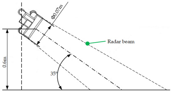
Figure 1.
Installation way of the radar speed sensor.
To validate the measurement accuracy of the radar sensor, the speed measurement results by the radar sensor and the Beidou navigation speed measurement system mounted on the tractor when the tractor advanced at different speeds (0.25, 0.5, 0.75, and 1 m/s) were obtained for accuracy comparison. During measurement, the tractor moved at a constant speed (after modification), and the sampling frequency was 10 Hz. The speed data when the tractor moved stably for 50 s were collected. The unmanned navigation tractor (Case Corporation, the U.S.) recorded the forward speeds via the industrial control computer. In contrast, the radar speed measurement sensor collected and recorded the speed information via the speed-dependent fertilization control terminal. To ensure measurement accuracy, the radar speed measurement sensor should ensure rational installation position and angle.
During the test, the radar sensor was installed at the back of the seeder. Figure 2 shows the radar speed sensor’s present data acquisition test site.
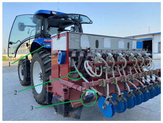
Figure 2.
Present data acquisition site by the radar speed sensor: 1—case unmanned navigation tractor; 2—speed-dependent fertilization control terminal; 3—radar speed sensor.
It can be observed from the test that the radar sensor showed more favorable data precision and stability than the Beidou system in speed measurement when the tractor moved at high and low speeds, suggesting better speed measurement performance and precision of the radar. The radar adopts a recursive average filtering method in speed measurement, with a high smoothness degree, which can reduce sudden rapid rotation of the fertilizer application motor induced by drastic fluctuation of the tractor speed, thereby achieving stable control of speed-dependent fertilization.
2.1.3. Overall Scheme of the Control System
After finishing the driving scheme of the fertilization equipment and the rotation speed feedback sensor and selecting the speed measurement device, the overall scheme of the speed-dependent fertilization control system of the spiral-disturbance conic centrifugal fertilizer discharge apparatus was developed based on the previously calibrated relation between rotation speed and fertilization application amount after the optimization of the fertilizer apparatus, as shown in Figure 3.
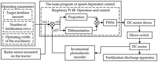
Figure 3.
Block diagram of the speed-dependent fertilization control system.
To enhance the control system’s accuracy and stability while considering further function expansion, this study adopted the Raspberry PI with strong anti-interference ability, abundant interfaces, and fast operating speed as the controller. As the control core, the Raspberry PI can handle and calculate the square wave signal returned by the speed measurement radar. Meanwhile, in combination with the machine’s operating parameters, the target rotation speed of the fertilizer discharge apparatus was obtained, and the controller adjusted the rotation speed of the apparatus by the target value. The photoelectric encoder connected with the fertilizer discharge via the belt sent the pulse of the rotation speed to the controller, and the fertilizer discharge apparatus adjusted the rotation speed in contrast with the target value, thereby forming closed-loop control and achieving precise control of fertilizer discharge amount.
During the field operation process, the fertilizer discharge apparatus can automatically stop when the machinery is lifted and turned and automatically rotate when the machinery is lowered. Accordingly, enhancing operating efficiency and quality can simplify the driver’s operation process. To achieve the goal, the micro-switch was added to the positive pole of the output end of the driver. The micro-switch Z-15HW24-B (Shenzhen Xingyi Electric, Shenzhen, China) was used. By connecting the positive pole of the output end of the driver with the positive pole of the DC motor via the COM (common end) and the NO (opening end) of the micro-switch, the latter was bonded to the left lower arm of the three-point suspension of the machinery. When the left lower cantilever of the three-point suspension of the tractor was rotated around the ball head, the micro-switch can be disconnected and switched via upper and lower probing of the end. When the machinery was lifted and turned in the field, the end probed upwards during the rotation of the left lower cantilever of the three-point suspension of the machinery around the ball head; accordingly, the switch was triggered and disconnected, and the DC motor stopped the operation on account of no voltage input. When the machinery fell, the end probed downwards during the rotation of the left upper cantilever, and the switch was returned and turned on; accordingly, the DC motor dove the fertilizer discharge apparatus to rotate and finish the fertilizer discharge.
The speed-dependent fertilization control system mainly consisted of the control program and hardware. Specifically, the hardware mainly included a human–machine interface, information acquisition, an electric drive module, and the controller. The controller calculated the target rotation speed according to the machinery’s operating parameters and the collected speed information, simultaneously compared with the actual rotation speed, and adjusted the corresponding PWM square wave signal and output to the driver of the DC motor via the PD control algorithm. The driver amplified the input control logic-level PWM square wave into the square wave with the motor’s operating voltage as the peak value but unchanged duty ratio and frequency.
To facilitate precise control of the motor speed, a relational expression was established linking the fertilizer discharge disc’s rotational speed nv with target fertilizer application amount Tf, machine width Cj, and forward speed Vq through preliminary experiments with different duty cycles, rotational speeds, and the fertilizer supply rates:
The above equation yields duty cycle values under different fertilization parameters, which can be used for precise control of the fertilizer apparatus rotation.
2.2. Establishment of the Control System Model and Algorithm Investigation
Based on the above analysis results, the 12 V permanent magnet brush DC reduction motor (2GN-50 K, Xuecheng Electric Co., Ltd., Shenzhen, China) was used for fertilizer discharge. According to Kirchhoff’s voltage laws and the motor’s equivalent circuit, the voltage equilibrium equation of the armature circuit can be written as follows:
where ua denotes the input armature voltage, with a unit of V; La is the inductance of the armature circuit, with a unit of H; ia is the armature current, with a unit of A; Ra is the armature resistance, with a unit of Ω; Ea is the counter potential of the armature, with a unit of V.
During the rotation process, the mechanical torque, the mechanical resistance moment, and the electromagnetic torque of the motor were all at an equilibrium state; after the simplification, the following expression can be derived as follows:
where Mm denotes the electromagnetic torque induced by the armature current, with a unit of N·m; Mc is the motor’s mechanical resistance moment, with a unit of N·m; J is the rotational inertia, with a unit of kg·m2, n denotes the motor speed, with a unit of rad/s.
To obtain the transfer function of the used DC motor, the Laplace transform was performed for Equations (2) and (3), yielding the following expression:
where Ce is the counter potential constant, with a unit of V/rpm; ϕ is the excitation magnetic flux, with a unit of Wb; Ta is the electromagnetic time constant of the DC motor, with a unit of s; and Tm is the mechanical time constant, with a unit of s.
Since some parameters of the gear motor can hardly be directly measured, the step response curve of the motor was collected and recognized with MATLAB 2020 to determine various parameters in the transfer function of a permanent magnetic brush gear motor. Figure 4 displays the present data acquisition site.
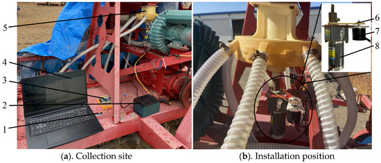
Figure 4.
Picture of the acquisition site of the step response curve of the DC motor. 1—USB to TTL module; 2—power supply; 3—acquisition card; 4—laptop computer; 5—fertilizer applicator; 6—pulley; 7—encoder; 8—DC geared motor.
The RLE38-06 rotary encoder (Sihong Yuede Electronic Trading Firm, Suqian, China) with two phases (a and b) was used in the present test. Two thousand five hundred pulses can be generated per revolution. The rotary coder’s optical coupler and grating code disc can identify the pulse signals with forward and reserve rotations. The motor and the encoder can be flexibly connected by the belt with the 3D-printed pulley installed on the motor shaft and the encoder shaft, during which the transmission ratio of the motor pulley to the encoder pulley was set at 1:2, i.e., 5000 pulse signals can be generated when the motor rotated by a circle. Data were collected at a sampling interval of 6 ms. The data in the first 800 ms were collected.
The MATLAB 2020 system identification toolbox possesses the function of calculating the system’s transfer function based on the input and the output data, which is a software package for processing discrete sampling data. Accordingly, many researchers have extensively applied the MATLAB 2020 system identification toolbox to identification theory. By taking the average of the above three test data, the second-order transfer function of the DC motor was determined. Using the MATLAB 2020 system identification toolbox, the step response curve of the DC motor was fitted to generate the identified image.
First, the input and output data were stored in MATLAB’s workspace. Then, after the system identification toolbox and the type of imported data were selected, some information was configured to load data. According to the above-described motor type, the transfer function model of the second-order system was adopted as the system’s identification model, and the identified system’s transfer function was defined as follows:
Since the Raspberry PI was adopted as the main control chip of the speed-dependent fertilization control system and the motor’s rotation was driven by controlling the driving module, the transfer function should also consider the voltage amplification by the driving module. To satisfy the requirements in speed-dependent control of the fertilizer discharge system and speed-dependent control of the subsequent seeding system, the L298N dual-channel H-bridge motor driver (Shenzhen Qianbaidu Electronic Technology Co., Ltd., Shenzhen, China.) was selected. The driver, featured by stable performance, can simultaneously control two permanent magnets brushless DC decelerating motors to take different actions. L298N [25] can amplify the input control logical level PWM square wave into the PWM square wave whose peak value was the motor’s operating voltage, but duty cycle and frequency remained unchanged:
where Kb is the amplification factor, and Ui(s) is the effective voltage on the input end, with a unit of V.
According to Equations (4) and (6), the second-order transfer function of the speed of the motor and the input voltage of the armature can be written as follows:
PD regulation is a widely used mature regulation method in present control systems, which can provide actuators with a scheme to rapidly and accurately reach the target. PD regulation was performed based on the above-determined transfer function of the DC motor. Using the PD regulation toolbox in MATLAB, PD parameters were tuned. The system entered into the stable state at t = 0.014 s, implying rotational speed stabilization and further fluctuation within a very small range.
2.3. Design of Software and Hardware of the Speed-Dependent Fertilization Control System
2.3.1. Circuit Design of Speed-Dependent Fertilization Control System
The speed-dependent fertilization control system should provide a stable and reliable power supply for the Raspberry PI, L298N dual-channel H-bridge motor driver, and the DC gear motor. The power supply circuit guarantees the stable operation of the speed-dependent fertilization control system, which mainly includes the voltage domains—3.3 V, 5 V, and 12 V, respectively. A voltage of 3.3 V was used to reduce the radar return voltage signal. The photoelectric encoder returns a voltage signal to the voltage that MCU, the voltage at 5 V, can recognize, which was used to supply power for the Raspberry PI. The voltage at 12 V was used to supply power for the DC gear motor and the DC motor driver.
Considering that the seeder always operates in the field for a long time, the 12 V battery mounted on the tractor acted as the main power of the control system. Before connecting with the main power, the control system was equipped with a secondary power supply (12V5A battery) for debugging convenience. The secondary battery can be charged when the control system is connected to the main power. Using the VRB1205YMD-20WR3 power module, the voltage at 12 V was reduced and stabilized to the voltage at 5 V; using the K7805-500 power module, 12 V was reduced and stabilized to 3.3 V. Figure 5 shows the schematic diagram of signal processing and power supply circuit.
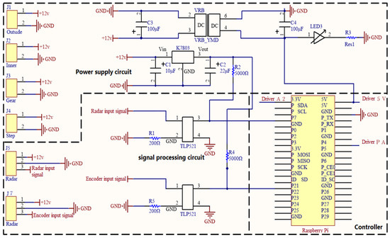
Figure 5.
Schematic diagram of the circuit in the present control system.
For the convenience of installation and debugging, the power source and signal processing module were connected to the Raspberry PI via the pin socket. Meanwhile, to facilitate heat dissipation, the PCB board near the Raspberry PI chip was hollowed out, and the power source and signal processing circuit board were connected with the DC gear motor driver through Dupont wires. The pins (5 V, PA, A1, A2, and G) of the DC gear motor driver were connected with the pins of the Raspberry PI (5 V, P4, GND, 3.3 V, and GND), in which PA is the output of PWM square wave and G is ground supply pin of the control board. At A1.A2 = 0.0, the machinery braked; at A1.A2 = 1.0, the machinery took clockwise rotation; at A1.A2 = 0.1, the machinery took anti-clockwise rotation.
2.3.2. Structural Composition of the Speed-Dependent Fertilization Control System
The speed-dependent fertilization control system was designed to facilitate operation and carry and directly display the fertilizer amount. The hardware composition is shown in Figure 6.
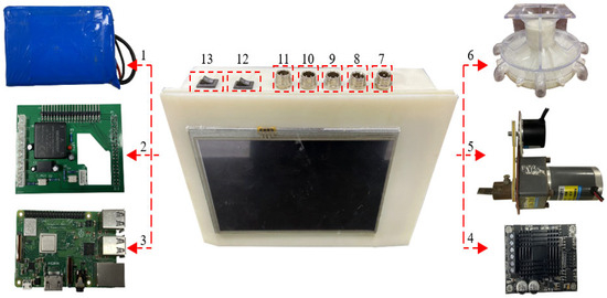
Figure 6.
Hardware composition of the developed speed-dependent fertilization control system: 1—secondary power source; 2—main power source and signal processing module; 3—Raspberry PI; 4—motor driver; 5—motor and photoelectric encoder; 6—fertilizer discharge apparatus; 7—encoder port; 8—radar port; 9—motor of the fertilizer discharge apparatus; 10—motor of the seeder; 11—port of the main power source; 12—switch of the main power source; 13—switch of the secondary power source.
The system mainly comprised the secondary power source, the main power source, the signal processing module, the Raspberry PI, the DC gear motor driver, the DC gear motor, the fertilizer discharge apparatus, the control box, and the display screen. For the convenience of assembly and disassembly, the aviation connector was installed on the control box to facilitate plug and pull. When the speed-dependent fertilization control system operated, the fertilization data mainly including the target fertilizer discharge amount, the operation width, and the number of fertilization rows) were input, the rotation information of the fertilization discharge shaft was timely obtained with the photoelectric encoder and compared with the input fertilization data and the target rotation speed of the DC gear motor (calculated by the forward information of the machinery measured by the radar sensor); next, using the PD control algorithm, the control system adjusted the corresponding PWM square wave signal and input to the DC gear motor driver to control the DC gear motor and drive the rotation of the fertilizer discharge fertilizer. During the operation, the display screen displayed the fertilization data in real time.
2.3.3. Program Design of the Speed-Dependent Fertilization Control System
After the control program started, the Raspberry PI finished the system initialization; meanwhile, the display screen and the clock finished the initialization, and the timer was started. The data processed by the radar sensor and the signal acquisition module of the encoder acted as the external interruption of the Raspberry PI pin. The counting program constantly updated the number of ascending edges in the return signal. The operating speed and the motor’s actual rotation speed were calculated. In combination with the preset target fertilizer amount, the PMW duty ratio was calculated and output to drive the rotation of the motor. Meanwhile, the fertilization data were displayed on the OLED screen in real time. The flowchart of the fertilization control program is shown in Figure 7.
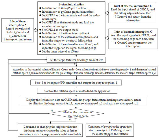
Figure 7.
Flowchart of the fertilization control program.
2.4. Constant- and Variable-Speed Fertilization Performance Tests
A constant-speed performance test was conducted to assess the error between the actual fertilizer amount and the target value when the machinery moved at a constant speed after the regulation by the control system. In this study, the experiment complied with the Technical Specification for Quality Evaluation of Fertilizing Machinery (NY/T 1003-2006), an agricultural industry standard of the People’s Republic of China [26], which specifies that the fertilization amount deviation (referred to as relative error in this paper) should be ≤15%. The Dongfanghong LX954-C tractor (China Yituo Group Co., Ltd., Luoyang, China.) was used, and the 12 V battery mounted on the tractor acted as the power source of the control system. During the test, the tractor operated in the field without stopping for 100 m; according to the fertilizer requirements, the minimum, medium, and maximum fertilizer application rates were set as the target fertilization amounts, respectively. That is, three groups of different target fertilizer discharge rates of 225, 375, and 525 kg/hm2 were established. Stanley compound fertilizer was used as the granular fertilizer in this study. The granular fertilizer was collected at the end of various fertilizer pipes with the bags and weighed. Figure 8 displays the test site.
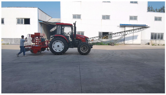
Figure 8.
Photo of fertilization performance test site.
A variable-speed fertilization performance test to validate the error between actual and target fertilizer discharge amounts of the developed speed-dependent fertilization control system in the operating region when the target fertilizer amount was set. The target fertilizer amounts were the same in the above constant-speed test. The tractor traveled without stopping for 100 m and started in the first gear; next, the tractor changed to the second and third gear after traveling for 30 and 60 m, respectively; finally, the tractor braked in the neutral position after traveling for 100 m. Before the test, the signs were set at 30 and 60 m, indicating the gear shift. The bags collected the granular fertilizer in various pipes and weighed to calculate the error.
The relative error Ex was calculated as follows:
where Rf and Tf denote the actual and target fertilizer discharge amounts, respectively, both with a unit of g.
2.5. Field Fertilization Performance Test
To further validate the reliability of the developed speed-dependent fertilization control system, a field test was performed at the test site of Jianli, Hubei, China. As shown in Figure 9, a Dongfanghong LX954-C tractor was used. The target fertilizer amount was set at different values (225, 375, and 525 kg/hm2, respectively). During the test, the tractor started in the first gear and then changed to the second and third gear after traveling for 30 m and 60 m, respectively; finally, the tractor braked in the neutral position after traveling for 100 m. The bags collected the granular fertilizer in various pipes, which were then weighed to calculate the error.
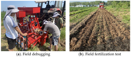
Figure 9.
Field performance test.
3. Experimental Results
Table 1 lists the constant- and variable-speed fertilization performance test results using the developed speed-dependent control system. The constant-speed fertilization performance test results exhibited the relative error between actual and target fertilizer discharge amounts below 2.82%. The relative error when the tractor traveled at a higher gear was larger than the condition at a lower gear, which may be attributed to the fact that the machinery underwent more violent shaking at higher speeds. However, the relative errors were all within the acceptable range. As can be seen from variable-speed fertilization performance test results, when the tractor traveled at high gear, the actual fertilizer discharge amount deviated greatly from the target value. The reasons can be described below. After the gear shift, the tractor underwent axial movement, and the fertilizer discharge apparatus rose rapidly, resulting in a great error in discharge amount. Meanwhile, since the tractor was manually operated, the consistency in gear shift time and the trampling intensity of the accelerator pedal can hardly be ensured, which also caused the error. However, the relative error between the actual fertilizer discharge amount and the target value was below 2.67% overall, within an acceptable range, satisfying the fertilization requirement. In the constant- and variable-speed fertilization performance tests, the errors were all within the requirements of national standards and below 3.11% [27], indicating that the developed speed-dependent control system exhibited good control accuracy.

Table 1.
Results of fertilization performance test.
Field Fertilization Performance Test Results
Table 2 displays the present field fertilization performance test results, from which it can be observed that the relative error between the actual total fertilizer discharge amount and the target value was below 3.43%. Because of uneven terrain in the field, the tractor may jump during travel, resulting in the vibration of the machinery and the vibration of the radar sensor installation frame. However, the relative error differed slightly from the value in paving test results. The test results in different groups satisfied the requirements in field fertilization, suggesting that the developed system showed favorable speed-dependent fertilization ability and favorable adaptivity in the field.
Table 2.
Variable-speed fertilization performance test results in the field.
4. Conclusions
This study developed a speed-dependent fertilization control system for rapeseed seeders based on high-precision radar speed sensors. The system adopted the Raspberry PI as the control core and processed the square wave signal returned by the radar sensor. Meanwhile, in combination with the machinery’s operating parameters, the target rotation speed of the fertilizer discharge apparatus was obtained; next, the rotation speed of the fertilizer discharge apparatus was adjusted in real-time according to the target rotation speed, and the rotation speed pulse was sent to the controller with the photoelectric encoder connected with the fertilizer discharge shaft. Accordingly, the rotation speed can be adjusted by comparing it with the target rotation speed to form the closed-loop control and achieve high-precision control of fertilizer discharge amount. Field performance tests revealed that the relative error between the actual fertilization amount and the target value was within an acceptable range, verifying the stability of the speed-adaptive fertilization control system. This provides a reference for variable-rate fertilization in rapeseed direct seeding, further promotes the popularization and application of fertilizer reduction and efficiency enhancement technologies in the region, and effectively alleviates environmental pollution caused by excessive fertilizer use. However, this study focuses on the research and application of low-cost control systems and is less suitable for precision fertilization operations. The follow-up study envisages further research on prescription map-based fertilization control systems using data fusion by integrating field fertility information.
Author Contributions
Conceptualization, X.L.; methodology, X.L.; software, X.L.; validation, X.L.; formal analysis, X.L.; data curation, X.L. writing—original draft preparation, X.L.; writing—review and editing, H.Z.; visualization, E.W.; supervision, L.Y.; project administration, Q.L. All authors have read and agreed to the published version of the manuscript.
Funding
This research was funded by the following fund projects: Doctoral Scientific Research Foundation of Pingdingshan University (PXY-BSQD-2023023); project of the Science and Technology Department of Henan Province under Grant 242102111172, Grant 242102111173 and Grant 242102220079.
Institutional Review Board Statement
Not applicable.
Informed Consent Statement
Not applicable.
Data Availability Statement
The original contributions presented in this study are included in the article. Further inquiries can be directed to the corresponding author.
Conflicts of Interest
E.W. was employed by Jinan Heavy Industry Engineering Co., Ltd. The remaining authors declare that the research was conducted in the absence of any commercial or financial relationships that could be construed as a potential conflict of interest.
References
- Ren, L.; Tian, M.; Li, J.; Zhan, C. Research Status and Development Analysis of Variable Fertilization Technology in China. J. Agric. Mech. Res. 2023, 10, 10–15+23. [Google Scholar]
- Shi, Y.; Chen, M.; Wang, X.; Odhiambo, M.O.; Zhang, Y.; Ding, W. Analysis and Experiment of Fertilizing Performance for Precision Fertilizer Applicator in Rice and Wheat Fields. Trans. Chin. Soc. Agric. Mach. 2017, 7, 97–103. [Google Scholar]
- An, X.; Wang, X.; Fu, W.; Wei, X.; Wu, G.; Li, L. Design and Experiment of Fertilizer Amount Control Algorithm in Four Factors Variable Rate Fertilization System. Trans. Chin. Soc. Agric. Mach. 2018, S1, 149–454. [Google Scholar]
- Ma, X.; Zhao, X.; Liu, S.; Wang, Y.; Wang, X.; Li, Z. Design and Experiment of Solid Particle Fertilizer Variable Rate Fertilization Device for High-speed Rice Transplanter. Trans. Chin. Soc. Agric. Mach. 2023, 9, 99–110. [Google Scholar]
- Jia, H.; Zheng, J.; Zhao, J.; Guo, M.; Zhuang, J.; Wang, Z.; Jia, H.; Zheng, J.; Zhao, J.; Guo, M.; et al. Design and Experiment of 2BDB-6(110) Soybean Bionic Intelligent Till-sowing Machine. Trans. Chin. Soc. Agric. Mach. 2018, 5, 93–107. [Google Scholar]
- Jin, X.; Li, Q.; Yuan, Y.; Qiu, Z.; Zhou, L.; He, Z. Design and Test of 2BFJ-24 Type Variable Fertilizer and Wheat Precision Seed Sowing Machine. Trans. Chin. Soc. Agric. Mach. 2018, 5, 84–92. [Google Scholar]
- Zhang, J.; Yan, S.; Ji, W.; Zhu, B.; Zheng, P. Precision Fertilization Control System Research for Solid Fertilizers Based on Incremental PID Control Algorithm. Trans. Chin. Soc. Agric. Mach. 2021, 3, 99–106. [Google Scholar]
- An, X.; Fu, W.; Wang, P.; Wei, X.; Li, L.; Meng, Z. Development of Variable Rate Fertilization Control System Based on Matching Fertilizer Line and Seed Line of Wheat. Trans. Chin. Soc. Agric. Mach. 2019, S1, 96–101. [Google Scholar]
- Xin, X. Experimental Study on the Variable Spraying Control System of Foliar Fertilizer for Soybeans. Master’s Thesis, Heilongjiang Bayi Agricultural University, Heilongjiang, China, 2023. [Google Scholar]
- Zhang, R. Research on the Control System of Synchronous Hole Fertilization During Corn Sowing. Master’s Thesis, Heilongjiang Bayi Agricultural University, Heilongjiang, China, 2023. [Google Scholar]
- Wang, H.; Liu, Y.; Zhou, L.; Zhou, H.; Niu, K.; Xu, M. Design and Test of Fertilizer Flow Piecewise PID Control System of Fertilizer Planter. Trans. Chin. Soc. Agric. Mach. 2023, 54, 32–40+94. [Google Scholar]
- Zhang, J.; Liu, G.; Ren, Z.; Zhang, D.; Jiang, B. Construction of a Discharge Prediction Model for the Fertilizer of a Bivariate Fertilization System Based on GWO-GRNN. Jiangsu Agric. Sci. 2023, 2, 210–217. [Google Scholar]
- Gong, H.; Wang, X. Research on Real-time Variable Topdressing of Corn Based on the Combination Model of Exponential Smoothing Algorithm. J. Heilongjiang August First Land Reclam. Univ. 2022, 6, 84–90. [Google Scholar]
- Wang, Z.; Zhang, B.; Liang, C.; Wang, H. Design and Experimental Study on Maize Variable Hole Fertilizer Control System. J. Heilongjiang August First Land Reclam. Univ. 2022, 34, 99–108. [Google Scholar]
- Wan, S.; He, R.; Yu, H.; Duan, Q.; Xu, G.; Sun, G. Design and experiment of fertilization control system with adaptive calibration function. J. South China Agric. Univ. 2024, 45, 88–96. [Google Scholar]
- Yang, L.; Zhao, L.; Zhang, J.; Lyu, S.; Hou, C.; Liu, G. Particle fertilizer mass flow measurement based on microwave method. Trans. Chin. Soc. Agric. Mach. 2023, 54, 323–329. [Google Scholar]
- Zhou, W.; Wu, X. Research on Variable Rate Fertilization Device with Electrical Control Characteristics. J. Agric. Mech. Res. 2024, 1, 112–115. [Google Scholar]
- Zhen, W.; Wang, C.; Yang, X.; Xing, H.; Yao, Z.; Qi, L. Design and experiment on the variable application regulation system of liquid fertilizer in rice. J. South China Agric. Univ. 2023, 4, 577–584. [Google Scholar]
- Cui, Y.; Tian, M.; Zhang, L.; Li, H.; Shan, Y.; Ma, X.; Fu, C. Study on Control Strategy and System of Subsection Variable Fertilization of Water and Fertilizer for Beet in Field. J. Agric. Mech. Res. 2023, 7, 42–46. [Google Scholar]
- Bai, J.; Tian, M.; Li, J. Analysis and Precision Test of Variable Fertilization Control System. J. Agric. Mech. Res. 2022, 9, 22–28. [Google Scholar]
- Liu, X.; Ding, Y.; Shu, C.; Liu, W.; Wang, K.; Du, C.; Wang, X. Design and experiment of spiral disturbance cone centrifugal fertilizer apparatus. Trans. Chin. Soc. Agric. Eng. 2020, 2, 40–49. [Google Scholar] [CrossRef]
- Liu, X.; Ding, Y.; Shu, C.; Wang, K.; Liu, W.; Wang, X. Mechanism Analysis and Test of Disturbance and Blockage Prevention of Spiral Cone Centrifugal Fertilizer Apparatus. Trans. Chin. Soc. Agric. Mach. 2020, 12, 44–54. [Google Scholar]
- Liu, X.; Hu, R.; Wang, D.; Lu, B.; Wang, W.; Ding, Y. Optimization and Test of Fertilizer Apparatus Based on Granular Fertilizer Movement Model. Trans. Chin. Soc. Agric. Mach. 2021, 52, 85–95. [Google Scholar]
- Zhang, C. Research and Experiment on Key Technology of Control System for Unmanned Seeding Operation of Rape Seed. Ph.D. Thesis, Huazhong Agricultural University, Wuhan, China, 2023. [Google Scholar]
- Wang, H. Design of Self-balancing Fishing Platform Based on Arduino UNO. Ind. Control Comput. 2024, 12, 155–156. [Google Scholar]
- NY/T 1003-2006; Technical Specification for Quality Evaluation of Fertilizer Machinery. Ministry of Agriculture of the People’s Republic of China: Beijing, China, 2006.
- He, Y.; Yang, Y.; Ge, X.; Wang, W. Simulation and experiment of influencing factors of fertilization accuracy based on variable rate fertilization system. J. Chin. Agric. Mech. 2023, 10, 51–57+86. [Google Scholar]
Disclaimer/Publisher’s Note: The statements, opinions and data contained in all publications are solely those of the individual author(s) and contributor(s) and not of MDPI and/or the editor(s). MDPI and/or the editor(s) disclaim responsibility for any injury to people or property resulting from any ideas, methods, instructions or products referred to in the content. |
© 2025 by the authors. Licensee MDPI, Basel, Switzerland. This article is an open access article distributed under the terms and conditions of the Creative Commons Attribution (CC BY) license (https://creativecommons.org/licenses/by/4.0/).