Abstract
The electrospinning technique can produce multifunctional polymeric devices by forming solid fibers from polymer solutions under a high-voltage electric field. Variations such as concentric needles yield core/shell fibers. This study evaluates the effects of applied voltage (12.5–20 kV) and tip-to-collector distance (12.5–20 cm) on the morphology and thermochemical behavior of PLGA/PVA fibers made by coaxial electrospinning compared with casting-produced membranes and monolithic fibers. Optimal coaxial fibers (597 ± 90 nm diameter) were produced at 15 cm/12.5 kV, exhibiting a well-defined core/shell structure (PVA core: ~100 nm; PLGA shell: ~50 nm) confirmed by laser scanning confocal (core solution labeled with fluorescein) and TEM. FTIR and TGA demonstrated nearly complete solvent removal in electrospun samples versus ~10% solvent retention in cast films. XRD analysis indicated that cast films (PLGAff) exhibited minimal crystallinity (Xc ≈ 0.1%), while electrospun PLGA (PLGAe) showed cold crystallization and higher crystallinity (Tcc ≈ 90.6 °C; Xc ≈ 2.45%). DSC detected two different Tg (≈43.2 °C and 52.8 °C) in the coaxial fibers, confirming distinct polymer domains with interfacial interactions. These results establish precise processing/structure relationships for defect-free coaxial fibers and provide fundamental design principles for hybrid systems in controlled drug delivery and tissue engineering applications.
1. Introduction
In the medical device industry, polymeric materials have become essential, especially regarding controlled release systems and tissue engineering [1,2]. In this context, techniques such as self-assembly, phase separation, and electrospinning are notable for their ability to generate nanometric structures with tunable physicochemical properties [3,4]. Among these approaches, electrospinning stands out as a versatile and economical option to produce nanofibrous membranes from polymeric solutions [5,6].
This technique is based on an electrohydrodynamic process in which a polymeric solution is extruded through a needle tip and exposed to a high-voltage electric field. An electrical potential is applied to the polymeric solution, inducing free charges within the solution to move in response to the electric field toward the oppositely charged electrode (metallic collector). When the voltage reaches a critical value that exceeds the surface tension of the polymeric solution, the solution forms a conical projection known as the Taylor cone. The apex of the Taylor cone ejects a charged jet that stretches along the electric field. Throughout this procedure, the solvent evaporates, leading to the deposition of continuous fibers on the collector, creating a complex nanofibrous structure [7,8,9].
Nanofibrous polymeric mats have a highly porous structure with small, interconnected pores. They provide a large surface area relative to their mass, a high aspect ratio, and good gas permeability. Additionally, they are flexible, easy to modify at the surface, and exhibit unique physicochemical properties due to their nanoscale dimensions [5,6,10,11].
The versatility of the electrospinning technique is enhanced by modifications of the electrospinning apparatus, such as the use of concentric needles, called coaxial electrospinning, which allow the creation of hierarchical architectures of core/shell fibers. Those fibers can incorporate polymers with complementary properties into an integrated structure, solutions containing active substances, or other complex solutions that would otherwise be incapable of being incorporated, thus creating multifunctional polymeric devices [12]. However, coaxial electrospinning presents additional challenges, such as the need to compatibilize solvents with different volatilities for each polymeric solution and precise control of key electrospinning parameters to prevent morphological defects [13,14]. Pant et al. [6] emphasize that the immiscibility of core and shell solutions is crucial for preserving jet stability, requiring careful solvent selection and precise adjustment of operating conditions.
In this context, seeking to incorporate various materials for the development of a multifunctional matrix focused on controlled release systems and cellular scaffolds, poly(l-lactide-co-glycolide) (PLGA) and poly(vinyl alcohol) (PVA) present themselves as promising choices for core/shell nanofibrous systems. The core/shell architecture specifically aims to leverage the complementary properties of these polymers. PLGA, a biodegradable and hydrophobic polyester, is used in controlled release systems due to its mechanical properties, adjustable degradation rate, and biocompatibility [15,16,17]. It is intended to provide structural integrity, modulate degradation kinetics, and control the release profile of encapsulated agents. PVA is a hydrophilic and biocompatible polymer that enables the encapsulation of water-soluble compounds (e.g., growth factors, drugs) and enhances cell adhesion [16,18]. Recent studies emphasize the significance of these material combinations in electrospun scaffolds for cellular support and controlled drug delivery. However, they identify scaffold morphology as a critical limitation influencing optimal biological performance [19,20].
This paper presents a systematic analysis of PLGA/PVA coaxial electrospinning, focusing on the fundamental parameters required to obtain core/shell fiber mats while comparing them to monolithic fiber mats (monolithic electrospinning) and traditional scaffold fabrication techniques (solvent casting). This comparison aims to elucidate the effect of the coaxial electrospinning technique on polymer chain conformation and, consequently, how different processing techniques may impact scaffold performance as medical devices.
Thus, we investigate the influence of electrospinning parameters—applied voltage (12.5–20 kV) and needle/collector distance (12.5–20 cm)—on the scaffolds’ morphological, physicochemical, and thermal properties. This assessment targets the scaffold’s structural integrity, the efficacy of PVA core encapsulation within the PLGA shell, the degree of crystallinity, and the thermal behavior, critical requirements for achieving the intended functionalities. The findings not only identify ideal processing conditions for producing defect-free core/shell fibers but also offer new perspectives on the structural design of hybrid systems, leveraging the interplay between hydrophobic and hydrophilic properties in electrospun core/shell fiber scaffolds for tissue engineering and controlled drug delivery.
2. Materials and Methods
2.1. Materials
Poly(l-lactide-co-glycolide) (PLGA) (LA:GA ratio 85:15, Mw = 331,700, PuraSorb® PLG 8531, Corbion, Amsterdam, The Netherlands) was used in pellet form. Poly(vinyl alcohol) (PVA) (Mw = 30,000–70,000, hydrolysis degree 87–90%, Sigma-Aldrich, Saint Louis, MO, USA) was employed as a powder. Chloroform PA (CHCl3, Vetec Química Fina LTDA, Rio de Janeiro, Brazil) and N,N-dimethylformamide (DMF, ACS grade ≥99.8%, Sigma-Aldrich) were used for the PLGA shell solution. The PVA core solution was prepared with distilled water. In the fluorescence microscopy analysis, fluorescein (Sigma Aldrich) was added to the PVA solution, and for the transmission electron microscopy analysis, potassium ferrocyanide (Sigma Aldrich) was added to the PVA solution.
2.2. Synthesis of PLGA/PVA Core/Shell Membranes via Electrospinning
The coaxial electrospinning setup consisted of a high-voltage power supply (Glassman High Voltage PS/FC 6p02.0-11, High Bridge, NJ, USA), two syringe pumps (KDS 100 series), a coaxial needle with an inner diameter of 0.5 mm (25 G) and an outer diameter of 0.8 mm (21 G), and, finally, a grounded metallic collector. The core solution (PVA) was prepared by dissolving 15% w/v polymer in distilled water at 80 °C for 3 h. The shell solution (PLGA) was obtained by dissolving 3% w/v polymer in a CHCl3:DMF mixture (4:1 v/v).
The solutions were injected with the aid of 5 mL plastic syringes at flow rates of 0.16 mL/h (core) and 0.5 mL/h (shell). Flow rates were chosen based on previous studies showing that the core flow rate must be at least one-third of the shell flow rate to maintain jet stability [21]. The applied voltage ranged from 12.5 kV to 20.0 kV, and the tip-to-collector distance (TCD) was adjusted between 12.5 cm and 17.5 cm. A schematic representation of the coaxial electrospinning setup is shown in Figure 1A. These operational parameters were configured based on our research group’s prior experience with electrospinning [21,22,23].
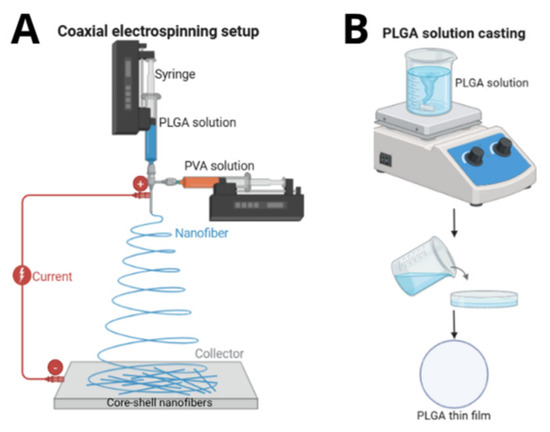
Figure 1.
Schematic representation of (A) coaxial electrospinning setup for PLGA/PVA membrane fabrication and (B) casting process for PLGA film preparation.
Experiments were conducted under controlled conditions (temperature: 22 ± 2 °C; relative humidity: 50 ± 5%) to minimize solvent evaporation variability. To ensure comparability between coaxial and monolithic fibers, all samples were prepared under identical conditions that were adapted to the specific requirements of each technique.
2.3. PLGA Membrane by Casting Technique
To understand the effect of electrospinning on the polymers, PLGA thin films were fabricated using the solution casting method for comparison. First, PLGA (LA:GA 85:15) was dissolved in chloroform (3% w/v) under magnetic stirring for 24 h at room temperature, forming a homogeneous, viscous solution. This solution was then poured into a Petri dish and placed in a desiccator at 30.0 ± 2.5 °C for 7 days to ensure complete solvent evaporation. During drying, the Petri dish was covered with a perforated lid to minimize environmental particle contamination while maintaining a slow, controlled evaporation rate. After drying, the thin films were carefully peeled from the mold and stored in a refrigerator at −4 °C. Figure 1B illustrates a schematic representation of the casting process.
2.4. Characterizations
2.4.1. Scanning Electron Microscopy (SEM)
Electrospun membranes were analyzed using a scanning electron microscope (TESCAN MIRA 4 LMU, Brno, Czech Republic) to evaluate fiber morphology, determine average fiber diameter, and identify structural defects. Samples were cut into 5 mm2 segments, mounted on metallic stubs, and sputter-coated with gold (Denton Vacuum Desk II), and images at 500×, 5000×, and 20,000× magnification were obtained. The average diameter was calculated using ImageJ® (v1.54g) software by measuring 50 continuous, non-overlapping fibers per field across five representative micrographs (5000×), following a validated methodology [22].
2.4.2. Transmission Electron Microscopy (TEM)
For TEM analysis, coaxial fibers were deposited directly onto carbon-coated copper TEM grids (Ted Pella, Redding, CA, USA). The grids were analyzed using a transmission electron microscope (Jeol 2100F, JEOL Ltd., Tokyo, Japan) to confirm the core/shell structure, assessing core (PVA) integrity and shell (PLGA) homogeneity. The sample’s core was stained with potassium ferrocyanide (Electron Microscopy Sciences, Hatfield, PA, USA), added at 0.5 wt% relative to the PVA mass. Inner diameter (core) and shell thickness were quantified by ImageJ® software based on contrast profiles and morphological features observed in micrographs.
2.4.3. Fluorescence Microscopy
To visualize the core, 0.15 g of fluorescein was added to the PVA solution during solubilization. Electrospinning was performed with a glass slide positioned on the metallic collector to capture the fibers. The slides were analyzed under a fluorescence microscope (LEICA DFC-310 FX, Wetzlar, Germany) with 488 nm excitation, enabling fluorescein visualization in the core and evaluation of coaxial fiber structural continuity.
2.4.4. Fourier Transform Infrared Spectroscopy (FTIR)
Membranes were analyzed using a Perkin Elmer Spectrum Frontier FT-IR/FIR spectrometer in ATR mode, with spectral scans ranging from 4000 to 600 cm−1. This characterization aimed to identify polymer functional groups and verify the removal of residual solvents (chloroform, DMF) by comparing the spectra of electrospun fibers and cast films.
2.4.5. X-Ray Diffraction (XRD)
Samples (2 cm2) were analyzed using a Rigaku ULTIMA IV X-ray diffractometer (Tokyo, Japan) (Cu-Kα radiation, λ = 1.5418 Å) with angular scans from 2θ = 2° to 60° (scan rate: 0.05 °/s). The technique was employed to assess material crystallinity and conformational changes induced by electrospinning, comparing diffraction peaks between electrospun and cast samples.
2.4.6. Thermogravimetric Analysis (TGA)
Membranes were heated from 25 °C to 700 °C (heating rate: 10 °C/min, N2 flow: 60 mL/min) using a TGA Q500 analyzer (New Castle, DE, USA). Data were used to determine thermal stability, initial degradation temperature (Tonset), and temperature of maximum mass loss rate (Tmax).
2.4.7. Differential Scanning Calorimetry (DSC)
This technique was employed to determine the glass transition temperature (Tg), crystallization temperature (Tc), melting temperature (Tm), melting enthalpy (ΔHm), and degree of crystallinity (Xc%). Thermal analyses were carried out using a Hitachi 700Q calorimeter (Tokyo, Japan), with ≈10 mg samples subjected to controlled thermal cycles under a nitrogen atmosphere (flow rate: 50 mL/min). Samples were first heated from 0 °C to 200 °C at 10 °C/min, followed by a 5-min isothermal hold at 200 °C. They were then cooled to 0 °C at the same rate before undergoing a second heating cycle from 0 °C to 100 °C at 10 °C/min. Transition temperatures and the melt enthalpy were determined using OriginPro® (version 2025) software.
The degree of crystallinity (Xc%) was calculated using the following equation [23]:
where ΔHm refers to the melt enthalpy, which is defined as the area under the endothermic melting peak (Tm) observed in the DSC curve during the first heating cycle. ΔHc is the crystallization enthalpy associated with Tc. is the theoretical melt enthalpy for a sample with 100% crystallinity. For PLGA, was assumed to be 106 J/g [21], while for PVA, the theoretical melt enthalpy for fully crystalline PVA was taken as = 138.6 J/g [23,24].
3. Results and Discussion
3.1. Evaluation of the Processing Parameters for the Production of Core/Shell Fibers
To evaluate the effects of the electrospinning parameters on the fiber core polymer, the membranes were split into four groups according to their respective TCD. Figure 2 presents the samples, their corresponding parameters, SEM images, and the resulting fiber diameters. The influence of processing parameters (voltage and needle-to-collector distance) on fiber morphology is evident when comparing the electrospinning parameters.
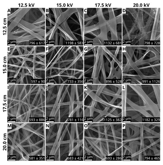
Figure 2.
SEM micrographs of PLGA/PVA core/shell nanofibers produced via coaxial electrospinning under varying processing parameters. (A–P) The images depict samples at a magnification of 20,000. The bar scale represents 2 μm.
At shorter distances (TCD = 12.5 cm), increasing the voltage from 12.5 to 20 kV resulted in fibers with highly variable diameters (796–1198 nm) and structural defects, including fiber rupture, interdigitations, and bead formation (Figure 2A–D). The sample obtained using 20 kV and 12.5 cm (Figure 2D) exhibited a distinct bimodal structure, where thinner fibers (~800 nm) coexisted with thicker ones (~1200 nm), indicating the collapse of the core/shell structure. These irregularities align with previous findings linking high voltages to Taylor cone instability, leading to polymeric jet disruptions, discontinuous flow, and secondary jet formation [25].
At an intermediate TCD (15 cm), lowering the voltage to 12.5 kV resulted in continuous, uniform fibers with an average diameter of 597 ± 90 nm (Figure 2E). This morphological consistency suggests that the combination of low voltage and moderate distance provided an optimal balance between electrostatic stretching and solvent evaporation, promoting stable nanofiber formation [26]. However, increasing the voltage to 15–20 kV (Figure 2F–H) led to needle-tip clogging and greater fiber diameter variability, resulting in structural defects. This outcome points out the importance of voltage regulation in coaxial electrospinning, where precise force control is essential to maintain stability when using immiscible polymer solutions [27].
In the group prepared with a TCD of 17.5 cm, the sample obtained using 15 kV (Figure 2J) can be highlighted due to the absence of defects and an average diameter of 781 ± 116 nm, while the sample obtained using 20 kV (Figure 2L) exhibited thicker fibers (1182 ± 329 nm), but equally uniform; in addition, both samples showed good spinnability. This progressive increase in diameter with increasing voltage is like what has been observed in several studies. The use of high voltages accelerates the jet toward the collector, reducing the time available for fiber solidification. Despite the longer distance, which theoretically favors stretching, the high kinetic energy of the jet in the sample obtained using 20 kV and 17.5 cm limited fiber elongation due to the short flight time for fiber deposition on the collector, resulting in thicker fibers [28,29,30,31].
Finally, samples produced with a TCD of 20 cm (Figure 2M–P) presented obstruction of the spinneret after about 5 min processing due to the solidification of the polymer and several defects. Increasing the distance between the needle and the metal collector decreased the strength of the electric field, destabilizing the Taylor cone and interrupting the continuous fiber formation [32,33].
Table 1 summarizes the processing parameters, average fiber diameter with standard deviation, observed defects, and qualitative assessment of electrospun matrices across all evaluated conditions. The performance of the electrospinning process varies from optimal to unviable, as determined by analyzing fiber diameter, the presence of morphological defects, and process stability.

Table 1.
PLGA/PVA coaxial electrospinning parameters (TCD and voltage), average diameter, defect summary, and performance.
SEM analyses demonstrated significant impacts of electrospinning parameters (applied voltage and needle/collector distance) on fiber morphology. Figure 3 displays the diameter variation of the defect-free fibers. A correlation between fundamental processing parameters, fiber morphology, and size can be observed, as the sample produced by using 15 cm and 12.5 kV exhibited uniform fibers with an average diameter of 597 ± 90 nm. The result suggests that the combination of low voltage and moderate distance promoted jet stability and ensured a balanced rate of solvent evaporation. Whereas the sample obtained at 15 cm, 15 kV produced fibers with an average diameter of 733 ± 356 nm. While the fibers were free of defects, a precipitate formed at the needle tip during electrospinning, leading to jet instability and reduced fiber production efficiency.
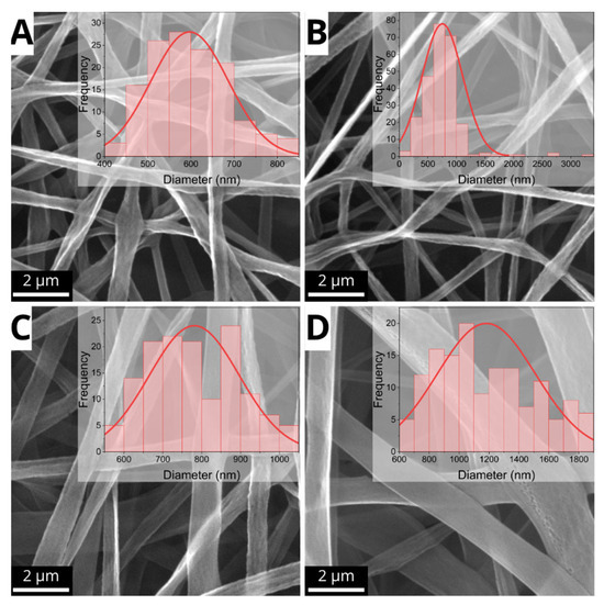
Figure 3.
Coaxial fibers with optimal morphological features and corresponding diameter histograms. (A) Am05 (15.0 cm, 12.5 kV); (B) Am06 (15.0 cm, 15.0 kV); (C) Am10 (17.5 cm, 15.0 kV); (D) Am12 (17.5 cm, 20.0 kV). The bar scale represents 2 μm.
It is interesting to note that the sample obtained at 17.5 cm and 15 kV showed continuous and uniform fibers with a diameter of 781 ± 116 nm, indicating that the higher TCD partially mitigated the effects of the moderate voltage, allowing controlled stretching of the polymer jet. Finally, the sample obtained using TCD = 17.5 cm and 20 kV, despite the high voltage, presented uniform but thicker fibers (1182 ± 329 nm), suggesting that the high distance decreased the efficiency of the electric field, limiting fiber thinning.
These results emphasize the importance of fine-tuning processing parameters to achieve optimal fiber characteristics. The sample obtained using TCD = 15 cm and 12.5 kV was the ideal condition for producing PLGA/PVA core/shell fibers, offering a balance of uniformity, reduced diameter, low dispersion, and defect-free structure.
To confirm the existence of a core/shell structure and the effectiveness of the encapsulation of the hydrophilic phase, fluorescence microscopy and transmission electron microscopy (TEM) were used. Fluorescence microscopy revealed the spatial distribution of coaxial fibers, with the PVA core uniformly distributed within the shell throughout the electrospun mesh (Figure 4A). The variable green fluorescence intensity along the fibers is indicative of coaxial systems, where core fluorescence is partially obscured by the outer layer, except in regions with decreased shell thickness or fiber overlaps. The overlapping of the bright field (Figure 4B) and the fluorescence field further confirms the hypothesis of the successful production of a membrane formed by core/shell fibers.
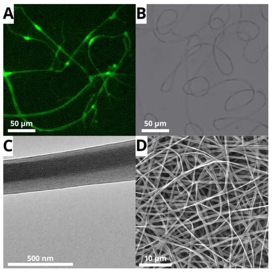
Figure 4.
Micrographs from (A) laser scanning confocal microscopy (core solution labeled with fluorescein), (B) bright field of PLGA/PVA sample, (C) transmission electron microscopy (TEM), and (D) scanning electron microscopy (SEM) of PLGA/PVA core/shell nanofibers (5000× magnification).
TEM analysis (Figure 4C) confirmed the fluorescence microscopy findings, revealing a well-defined structure with an approximately 97.39 ± 17.25 nm PVA core surrounded by a 57.15 ± 20.65 nm PLGA shell, resulting in an average total diameter of ~212 nm. These results align with SEM information for the chosen sample (597 ± 90 nm; Figure 4C). The variation in diameter measurements is mostly due to differences in characterization techniques, sample preparation processes, and measurement protocols.
When compared to thin films, electrospun structures can excel in drug delivery, tissue engineering, and functional coating [34,35,36]. However, important physicochemical properties of these structures are highly related to conformational changes in the polymeric chain caused by the spinning process when compared to traditional thin films. Therefore, it is important to understand these changes, and for this work, an intense investigation was performed by comparing the properties of films formed by monolithic and core/shell electrospun fibers and cast thin films.
3.2. Physicochemical Properties Evaluation
Fourier Transform Infrared Spectroscopy (FTIR) analysis was employed to investigate the surface chemical composition of PLGA/PVA core/shell fibers in comparison to monolithic PLGA and PVA fibers and the PLGA thin films. As shown in Figure 5, the spectra of coaxial fibers resemble the characteristic bands of PLGA, while key vibrational changes linked to PVA are absent, corroborating the hypothesis of complete encapsulation of the PVA core by the PLGA shell.
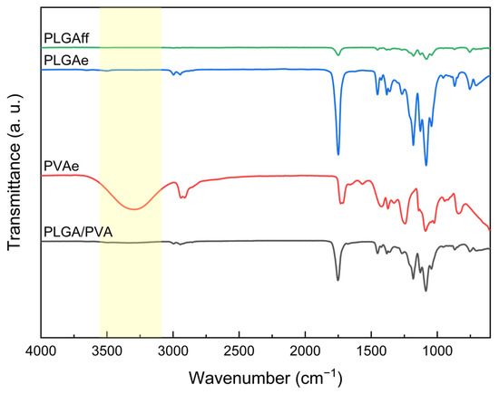
Figure 5.
FTIR spectra of cast film (PLGAff) and electrospun matrices (PLGAe, PVAe, and PLGA/PVA).
For monolithic PLGA fibers, the identified vibrational modes are consistent with the classic bands found in the literature. The pronounced band at 1740–1760 cm−1, associated with carbonyl (C = O) stretching, confirms the existence of ester groups, while peaks at 1300–1150 cm−1 are attributed to asymmetric C–O bond stretching, characteristic of the PLGA polymer chain [23,37]. Signals between 2850 and 3000 cm−1, associated with aliphatic CH3 and CH2 stretching, reinforce the polymer’s hydrophobic characteristic.
In contrast, the PVA spectrum presents a broad band in the range of 3200–3600 cm−1, characteristic of hydroxyl (–OH) groups, in addition to peaks at 1090 cm−1 (C–O stretching) and 2940 cm−1 (asymmetric CH2) [21]. The absence of PVA bands in the PLGA/PVA spectrum (Figure 5) suggests that the polymer is not present either on the fiber surface or in fiber defects that would result in PVA fibers, aligning with the morphology observed in the micrographs. These observations must be interpreted considering the technique’s limited penetration depth (~0.5–2 µm) [21]; this conclusion could only be drawn due to its alignment with the morphological evidence from micrographs. This behavior indicates the development of a core/shell structure, wherein the external PLGA layer acts as a physical barrier, masking the functional groups of the PVA core.
The similarity between the coaxial fiber spectrum and pure PLGA indicates a lack of substantial chemical interactions between the shell and core polymers, as expected in successful coaxial systems where the core and shell maintain distinct chemical identities [38].
Confirmation of PVA encapsulation by PLGA using FTIR is essential for applications requiring core isolation, such as controlled drug release. The hydrophilicity of PVA, essential for encapsulating water-soluble compounds, is preserved in the core, while the PLGA shell provides protection against premature degradation and facilitates gradual agent release. Moreover, the absence of –OH groups on the coaxial fiber surface may reduce non-specific protein adhesion in physiological environments, which is an advantageous feature for implants [39].
XRD analysis compared the structural organization of electrospun PLGA and PVA membranes with those produced via casting while also assessing the influence of core/shell architecture on polymer crystallinity. XRD curves are displayed in Figure 6.
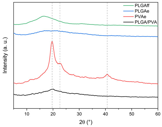
Figure 6.
Diffractograms of casting film (PLGAff) and electrospun matrices (PLGAe, PVAe, and PLGA/PVA).
The XRD curves of PLGAe (electrospun) and PLGAff (thin film) shown in Figure 6 reveal significant differences in molecular order. While the cast film exhibited a narrowed amorphous halo around 2θ = 15–25°, suggesting partial polymer chain organization, the electrospun membrane maintained a predominant amorphous structure. This contrast arises from distinct processing conditions: during casting, the slow solvent evaporation facilitated partial molecular rearrangement without the formation of well-defined crystallites, a characteristic of low-order semicrystalline polymers [40,41,42]. In contrast, the ultrafast solidification during electrospinning kinetically constrained PLGA chains in an ordered conformation while suppressing the formation of crystalline structures [43,44,45]. A similar behavior was observed in the work developed by Bhattarai et al. [46] when they studied the effect of the processing technique (casting vs. electrospinning) on poly(lactic acid) (PLA) for drug delivery.
For electrospun PVA fibers (PVAe), peaks at 2θ = 19.7°, 22.5°, and 40.7° (Figure 6) confirm the polymer’s semicrystalline characteristics, consistent with organized domains of hydroxylated chains [47]. The predominant peak at 19.7°, attributed to the PVA (101) diffraction plane, indicates orderly chain packing facilitated by intermolecular hydrogen bonding [48]. However, in PLGA/PVA core/shell fibers, this peak appears as a subtle inflection within PLGA’s amorphous halo, suggesting that rapid solvent evaporation from the shell solution restricts PVA chain mobility in the core, inhibiting crystal nucleation [49,50,51].
The predominance of amorphous characteristics in core/shell fibers may benefit applications requiring controlled degradation, as less ordered regions are more susceptible to hydrolysis [52].
3.3. Thermal Properties Evaluation
Thermogravimetric analysis (TGA) and differential scanning calorimetry (DSC) were performed to evaluate how processing techniques and core/shell architecture influence thermal stability, transitions, and crystallinity. Thermogravimetric analysis (TGA) and derivative thermogravimetry (DTG) were used to evaluate the thermal degradation profile of the samples, degradation onset temperature (TOnset), and maximum degradation rate temperature, as shown in Figure 7.
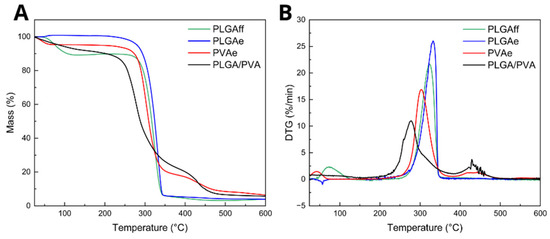
Figure 7.
(A) Thermogravimetric analyses and (B) derivative thermogravimetry of cast (PLGAff) and electrospun matrices (PLGAe, PVAe, PLGA/PVA).
The TGA demonstrated that electrospinning under the adopted parameters ensured complete solvent evaporation in monolithic PLGA (PLGAe) and the core/shell fibers, whereas the cast film (PLGAff) retained approximately 10% residual solvent, indicating electrospinning enabled full solvent evaporation during fiber formation [53]. It is important to note that the boiling temperature of chloroform is 61.2 °C, coinciding with the first TOnset value observed for PLGAff (Table 2). This difference is attributed to rapid solvent evaporation during electrospinning versus slow film drying in casting, which trapped solvent in the film’s internal regions [54,55].
Table 2.
Thermal degradation parameters (TGA/DTG) of cast films and electrospun matrices: onset temperatures (TOnset) and peak degradation temperatures (DTG) for each degradation stage.
The absence of characteristic chloroform peaks in electrospun samples, unlike cast membranes, confirms the efficiency of electrospinning in solvent removal. The literature suggests that residual chloroform in biomaterials may pose biological risks, including reported associations with cytotoxicity, oxidative stress, and protein denaturation, leading to impaired cell viability, enzyme inhibition, or DNA damage. Additionally, studies indicate that residual solvent might hinder cell adhesion, trigger inflammatory responses, and compromise the biocompatibility of biomaterials [56].
The monolithic PVA fiber (PVAe) exhibited an initial peak at approximately 32.9 °C, attributed to moisture evaporation, followed by two main stages of weight loss: the first at 284.4 °C, corresponding to chain stripping due to dehydration of the PVA polymer, and the second at 409.2 °C, likely related to chain scission and thermal decomposition [57,58].
Core/shell fibers (PLGA/PVA) exhibited two TOnset values at 254.1 °C and 415.4 °C. The first degradation event overlaps PLGA and PVA chain degradation, as their main degradation events occur at close temperatures (PLGA: ~305 °C; PVA: ~284 °C). The second event likely corresponds to residual PVA post-degradation. Table 2 summarizes these temperatures.
Differential scanning calorimetry (DSC) analysis of PLGA thin films (PLGAff) revealed an endothermic peak at 58.9 °C, attributed to residual solvent, in agreement with thermogravimetric analysis (TGA). The residual solvent acted as a plasticizer, reducing the glass transition temperature (Tg) of the material [59,60]. In other words, the solvent’s action diminishes intermolecular forces within polymer chains, consequently lowering the temperature at which amorphous-phase chains gain long-range molecular mobility. Furthermore, DSC highlighted significant processing-induced variations in thermodynamic properties. Figure 8 shows the DSC curves, and Table 3 exhibits the thermal transitions obtained for each sample.
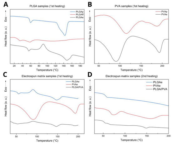
Figure 8.
DSC profiles of (A) PLGA samples, (B) PVA samples, and electrospun matrix samples: (C) 1st heating and (D) 2nd heating.
Table 3.
Thermal transitions and crystallinity degree of cast films and electrospun matrices.
The integration of XRD and DSC findings demonstrated the susceptibility of PLGA crystallization under the processing conditions. Although the cast film (PLGAff) exhibited a reduced amorphous halo (Figure 6), it showed low crystallinity (Table 3), which suggests that localized chain ordering is associated with L-lactic acid segments forming helical conformations without complete crystal formation. The gradual evaporation of solvent during casting allowed partial alignment of lactic acid (LA) segments; however, the presence of residual solvent (about 10%) and glycolic acid (GA) units destabilized the creation of full crystals [61].
In the electrospun PLGA fibers (PLGAe), chain reorganization during heating (Tcc ~90.6 °C) enabled crystalline domain formation, which was absent initially, resulting in a degree of crystallinity of 2.45% (Table 3). This crystalline behavior is not observed in XRD (conducted at room temperature), which shows only an amorphous halo.
The reduced Tg in electrospun PVA (PVAe, Tg = 91.0 °C) compared to commercial PVA (PVAp, Tg = 115.3 °C) highlights the plasticizing effect of water in hydrophilic polymers processed in environments with a certain degree of moisture [49]. The increase in the degree of crystallinity of PVAe (Xc = 21.2%) compared to the PVAp sample (PVAp, Xc = 11.1%) is attributed to molecular alignment facilitated by electrostatic stretching during the electrospinning process.
In cast PLGA films (PLGAff), the low crystallinity (Xc = 0.1%) suggests that residual solvent acts as a plasticizer, hindering polymer chain rearrangement. In contrast, electrospun monolithic membranes (PLGAe) exhibited a cold crystallization temperature (Tcc = 90.6 °C) and a degree of crystallinity of 2.45%, indicating that the rapid stretching during electrospinning kinetically traps polymer chains in an ordered state and only relaxes when sufficiently high energy is applied at temperatures above the Tg [62].
For core/shell PLGA/PVA fibers, the presence of two distinct glass transition temperatures (Tg = 43.2 °C and 52.8 °C) suggests phase separation between PLGA and PVA, with some degree of physical interaction, as evidenced by Tg values lower than those of monolithic fibers. We hypothesize that these result from trapped water in the core acting as a PVA plasticizer, facilitated by faster solidification of the PLGA shell due to higher solvent volatility [63]. This microstructure preserves the individual characteristics of each polymer and enables synergistic combinations of their properties. Furthermore, as evidenced by diffractograms, the PLGA/PVA scaffold exhibited a reduced characteristic crystalline fraction of PVA. This finding is corroborated by DSC data showing lower Tg values (52.8 °C) compared to highly crystalline monolithic fibers (PVAe, Tg = 91.0 °C), indicating enhanced long-range molecular mobility in amorphous domains, thereby accelerating dissolution. This effect is mitigated by the hydrophobic PLGA shell, which limits the dissolution of the PVA core, making this architecture particularly suitable for controlled drug delivery systems [64,65]. Detailed values are presented in Table 3.
The second DSC heating cycle showed PLGA samples with only one transition (Tg = ~55 °C) (Figure 8D). The PVA curves were similar, showing a Tg of approximately 73 °C, a Tm of around 150 °C, and comparable crystallinity (Figure 8D). PLGA/PVA exhibited two Tg values (52.5 °C and 63.6 °C) and a Tm of 148.7 °C (Figure 8D). Second-cycle temperatures are summarized in Table 3.
4. Conclusions
Coaxial PLGA/PVA fibers with uniform morphology were developed, in which the PVA core (~100 nm) is fully encapsulated by the PLGA shell (~50 nm) under conditions of 15 kV and 15 cm, as evidenced by SEM, TEM, and fluorescence microscopy. From FTIR and TGA, it was evidenced that the electrospun matrices completely eliminate solvent, unlike the membranes obtained by casting. XRD and DSC analyses showed that the crystalline profile varies according to the technique: the cast film (PLGAff) exhibits very low crystallinity (Xc ≈ 0.1%), whereas the electrospun fibers (PLGAe) display cold crystallization and higher crystallinity (Tcc ≈ 90.6 °C; Xc ≈ 2.45%). In coaxial electrospinning, PVA crystallization is suppressed, and part of the solvent remains in the core, acting as a plasticizer, in addition to two observed Tg values (≈43.2 °C and 52.8 °C), confirming the expected two phases of core/shell fibers. Future studies to evaluate porosity, drug release profile, and in vitro biological activity are needed to complement this work.
Author Contributions
Conceptualization, T.R.S.R., A.L.M.M.T., and M.L.D.; Methodology, T.R.S.R., A.L.M.M.T., and M.L.D.; Validation, A.L.M.M.T. and M.L.D.; Formal analysis, T.R.S.R. and A.L.M.M.T.; Investigation, T.R.S.R.; Writing—original draft, T.R.S.R.; Writing—review and editing, A.L.M.M.T. and M.L.D.; Supervision, A.L.M.M.T. and M.L.D.; Project administration, M.L.D.; Funding acquisition, M.L.D. All authors have read and agreed to the published version of the manuscript.
Funding
Coordenação de Aperfeiçoamento de Pessoal de Nível Superior (CAPES) (Grant 88887.620226/2021-00), Conselho Nacional de Desenvolvimento Científico e Tecnológico (CNPq) (Grant 307364/2018-6 and 310337/2023-2), FAPERJ (MLD, Grants E-26/202.538/2019 and 200.359/2023; AMTT, Grants E-26/204.558/2021 and E-26/204.559/2021; TRSR, Grant E-26/204.089/2022), and Project 022019 Nanotechnology Research Networks Program in the State of Rio de Janeiro (Grant E-26/010.000979/2019).
Data Availability Statement
The data is available upon request.
Acknowledgments
The authors acknowledge the LABNANO/CBPF facility in Rio de Janeiro for access to the JEOL JEM-2100F Transmission Electron Microscope.
Conflicts of Interest
The authors declare that there are no conflicts of interest in this manuscript.
Abbreviations
The following abbreviations are used in this manuscript:
| PLGA | Poly(lactic-co-glycolic acid) |
| PVA | Poly(vinyl alcohol) |
| SEM | Scanning Electron Microscopy |
| TEM | Transmission Electron Microscopy |
| FTIR | Fourier Transform Infrared Spectroscopy |
| TGA | Thermogravimetric Analysis |
| XRD | X-Ray Diffraction |
| DSC | Differential Scanning Calorimetry |
| LA:GA | Lactide:Glycolide |
| Mw | Molecular weight |
| DMF | N,N-dimethylformamide |
| TCD | Tip to collector distance |
| CHCl3 | Chloroform |
| Tonset | Initial degradation temperature |
| Tmax | Temperature of maximum mass loss rate |
| Tg | Glass transition temperature |
| Tc | Crystallization temperature |
| Tm | Melting temperature |
| ΔHm | Melting enthalpy |
| Xc% | Degree of crystallinity |
| ΔHc | Crystallization enthalpy |
| Theoretical melt enthalpy | |
| PLGAp | Commercial poly(lactic-co-glycolic acid) |
| PLGAff | Cast film poly(lactic-co-glycolic acid) |
| PLGAe | Electrospun matrix of poly(lactic-co-glycolic acid) |
| PVAp | Commercial poly(vinyl alcohol) |
| PVAe | Electrospun matrix of poly(vinyl alcohol) |
| PLGA/PVA | Core/shell fiber of poly(lactic-co-glycolic acid)/poly(vinyl alcohol) |
| PLA | Poly(lactic acid) |
| DTG | Derivative thermogravimetry |
References
- Kenry; Lim, C.T. Nanofiber Technology: Current Status and Emerging Developments. Prog. Polym. Sci. 2017, 70, 1–17. [Google Scholar] [CrossRef]
- Xue, J.; Wu, T.; Dai, Y.; Xia, Y. Electrospinning and Electrospun Nanofibers: Methods, Materials, and Applications. Chem. Rev. 2019, 119, 5298–5415. [Google Scholar] [CrossRef] [PubMed]
- Wade, R.J.; Burdick, J.A. Advances in Nanofibrous Scaffolds for Biomedical Applications: From Electrospinning to Self-Assembly. Nano Today 2014, 9, 722–742. [Google Scholar] [CrossRef]
- Khorshidi, S.; Solouk, A.; Mirzadeh, H.; Mazinani, S.; Lagaron, J.M.; Sharifi, S.; Ramakrishna, S. A Review of Key Challenges of Electrospun Scaffolds for Tissue-Engineering Applications. J. Tissue Eng. Regen. Med. 2016, 10, 715–738. [Google Scholar] [CrossRef]
- Okutan, N.; Terzi, P.; Altay, F. Affecting Parameters on Electrospinning Process and Characterization of Electrospun Gelatin Nanofibers. Food Hydrocoll. 2014, 39, 19–26. [Google Scholar] [CrossRef]
- Pant, B.; Park, M.; Park, S.-J. Drug Delivery Applications of Core-Sheath Nanofibers Prepared by Coaxial Electrospinning: A Review. Pharmaceutics 2019, 11, 305. [Google Scholar] [CrossRef]
- Vonch, J.; Yarin, A.; Megaridis, C.M. Electrospinning: A Study in the Formation of Nanofibers. J. Undergrad. Res. Univ. Ill. Chic. 2007, 1, 1–5. [Google Scholar] [CrossRef]
- Braghirolli, D.I.; Steffens, D.; Pranke, P. Electrospinning for Regenerative Medicine: A Review of the Main Topics. Drug Discov. Today 2014, 19, 743–753. [Google Scholar] [CrossRef]
- Sui, T.; Ying, S.; Titov, K.; Dolbnya, I.P.; Tan, J.-C.; Korsunsky, A.M. Operando Observation of the Taylor Cone during Electrospinning by Multiple Synchrotron X-Ray Techniques. Mater. Des. 2016, 110, 933–934. [Google Scholar] [CrossRef]
- Sperling, L.E.; Reis, K.P.; Pranke, P.; Wendorff, J.H. Advantages and Challenges Offered by Biofunctional Core-Shell Fiber Systems for Tissue Engineering and Drug Delivery. Drug Discov. Today 2016, 21, 1243–1256. [Google Scholar] [CrossRef]
- Reis, K.P.; Sperling, L.E.; Teixeira, C.; Paim, Á.; Alcântara, B.; Vizcay-Barrena, G.; Fleck, R.A.; Pranke, P. Application of PLGA/FGF-2 Coaxial Microfibers in Spinal Cord Tissue Engineering: An in Vitro and in Vivo Investigation. Regen. Med. 2018, 13, 785–801. [Google Scholar] [CrossRef] [PubMed]
- Haider, A.; Haider, S.; Kang, I.-K. A Comprehensive Review Summarizing the Effect of Electrospinning Parameters and Potential Applications of Nanofibers in Biomedical and Biotechnology. Arab. J. Chem. 2018, 11, 1165–1188. [Google Scholar] [CrossRef]
- Bhardwaj, N.; Kundu, S.C. Electrospinning: A Fascinating Fiber Fabrication Technique. Biotechnol. Adv. 2010, 28, 325–347. [Google Scholar] [CrossRef] [PubMed]
- Gonçalves, R.P. Avaliação Morfológica de Nanofibras Poliméricas Com Estrutura Núcleo-Casca Obtidas Por Eletrofiação Coaxial Para Aplicações Biomédicas. Ph.D. Thesis, Federal University of Rio de Janeiro, Instituto de Macromoléculas Professora Eloísa Mano, Rio de Janeiro, Brazil, 2015. [Google Scholar]
- Haghighat, F.; Ravandi, S.A.H. Mechanical Properties and in Vitro Degradation of PLGA Suture Manufactured via Electrospinning. Fiber. Polym. 2014, 15, 71–77. [Google Scholar] [CrossRef]
- Zhang, Q.; Li, Y.; Lin, Z.Y.W.; Wong, K.K.Y.; Lin, M.; Yildirimer, L.; Zhao, X. Electrospun Polymeric Micro/Nanofibrous Scaffolds for Long-Term Drug Release and Their Biomedical Applications. Drug Discov. Today 2017, 22, 1351–1366. [Google Scholar] [CrossRef]
- Rahmani, F.; Atabaki, R.; Behrouzi, S.; Mohamadpour, F.; Kamali, H. The Recent Advancement in the PLGA-Based Thermo-Sensitive Hydrogel for Smart Drug Delivery. Int. J. Pharm. 2023, 631, 122484. [Google Scholar] [CrossRef]
- Kumar, A.; Sood, A.; Han, S.S. Poly(Vinyl Alcohol)-Alginate as Potential Matrix for Various Applications: A Focused Review. Carbohydr. Polym. 2022, 277, 118881. [Google Scholar] [CrossRef]
- Ren, W.; Yu, X.; Chen, L.; Shi, T.; Bou-Akl, T.; Markel, D.C. Osteoblastic Differentiation and Bactericidal Activity Are Enhanced by Erythromycin Released from PCL/PLGA-PVA Coaxial Nanofibers. J. Biomater. Appl. 2022, 37, 712–723. [Google Scholar] [CrossRef]
- Zhang, H.; Ji, D.; Zhao, K.; Li, Z.; Yang, S.; Wang, P.; Cao, W.; Sun, Y. Potential applications of PLGA/PVA coaxial nanofibers with controlled release for guiding tissue regeneration. Mater. Res. Express 2025, 12, 015403. [Google Scholar] [CrossRef]
- Gonçalves, R.P.; da Silva, F.F.F.; Picciani, P.H.S.; Dias, M.L. Morphology and Thermal Properties of Core-Shell PVA/PLA Ultrafine Fibers Produced by Coaxial Electrospinning. Mater. Sci. Appl. 2015, 6, 189–199. [Google Scholar] [CrossRef]
- Toledo, A.L.M.M. Desenvolvimento de Membranas e Canas de Guias Neurais Por Eletrofiação Para o Tratamento de Lesões Por Transecção de Nervo Isquiático Em Camundongos C57BL/6. Ph.D. Thesis, Federal University of Rio de Janeiro, Instituto de Macromoléculas Professora Eloísa Mano, Rio de Janeiro, Brazil, 2020. [Google Scholar]
- Chor, A.; Gonçalves, R.P.; Costa, A.M.; Farina, M.; Ponche, A.; Sirelli, L.; Schrodj, G.; Gree, S.; de Andrade, L.R.; Anselme, K.; et al. In Vitro Degradation of Electrospun Poly(Lactic-Co-Glycolic Acid) (PLGA) for Oral Mucosa Regeneration. Polymer 2020, 12, 1853. [Google Scholar] [CrossRef] [PubMed]
- Patel, A.K.; Bajpai, R.; Keller, J.M. On the Crystallinity of PVA/Palm Leaf Biocomposite Using DSC and XRD Techniques. Microsyst. Technol. 2014, 20, 41–49. [Google Scholar] [CrossRef]
- Yarin, A.L.; Kataphinan, W.; Reneker, D.H. Branching in Electrospinning of Nanofibers. J. Appl. Phys. 2005, 98, 064501. [Google Scholar] [CrossRef]
- Asmatulu, R.; Khan, W.S. Historical Background of the Electrospinning Process. In Synthesis and Applications of Electrospun Nanofibers, 1st ed.; Asmatulu, R., Khan, W.S., Eds.; Elsevier: London, UK, 2019; pp. 17–39. [Google Scholar]
- Ahmadi Bonakdar, M.; Rodrigue, D. Electrospinning: Processes, Structures, and Materials. Macromol 2024, 4, 58–103. [Google Scholar] [CrossRef]
- Long, Y.-Z.; Yan, X.; Wang, X.-X.; Zhang, J.; Yu, M. Electrospinning: The Setup and Procedure. In Electrospinning: Nanofabrication and Applications; Ding, B., Wang, X., Yu, J., Eds.; Elsevier: London, UK, 2019; pp. 21–52. [Google Scholar]
- Bakar, S.S.S.; Fong, K.C.; Eleyas, A.; Nazeri, M.F.M. Effect of Voltage and Flow Rate Electrospinning Parameters on Polyacrylonitrile Electrospun Fibers. IOP Conf. Ser. Mater. Sci. Eng. 2018, 318, 012076. [Google Scholar] [CrossRef]
- Liu, Y.; Dong, L.; Fan, J.; Wang, R.; Yu, J.-Y. Effect of Applied Voltage on Diameter and Morphology of Ultrafine Fibers in Bubble Electrospinning. J. Appl. Polym. Sci. 2011, 120, 592–598. [Google Scholar] [CrossRef]
- Garg, K.; Bowlin, G.L. Electrospinning Jets and Nanofibrous Structures. Biomicrofluidics 2011, 5, 13403. [Google Scholar] [CrossRef]
- Chowdhury, M.; Stylios, G.K. Effect of Experimental Parameters on the Morphology of Electrospun Nylon 6 Fibres. Int. J. Basic Appl. Sci. 2010, 10, 70–78. [Google Scholar]
- Lee, J.S.; Choi, K.H.; Ghim, H.D.; Kim, S.S.; Chun, D.H.; Kim, H.Y.; Lyoo, W.S. Role of Molecular Weight of Atactic Poly(Vinyl Alcohol) (PVA) in the Structure and Properties of PVA Nanofabric Prepared by Electrospinning. J. Appl. Polym. Sci. 2004, 93, 1638–1646. [Google Scholar] [CrossRef]
- Zulkifli, M.Z.A.; Nordin, D.; Shaari, N.; Kamarudin, S.K. Overview of Electrospinning for Tissue Engineering Applications. Polymers 2023, 15, 2418. [Google Scholar] [CrossRef]
- Wildy, M.; Lu, P. Electrospun Nanofibers: Shaping the Future of Controlled and Responsive Drug Delivery. Materials 2023, 16, 7062. [Google Scholar] [CrossRef] [PubMed]
- Yang, Y.; Zhang, R.; Liang, Z.; Guo, J.; Chen, B.; Zhou, S.; Yu, D. Application of Electrospun Drug-Loaded Nanofibers in Cancer Therapy. Polymers 2024, 16, 504. [Google Scholar] [CrossRef] [PubMed]
- Meng, Z.X.; Wang, Y.S.; Ma, C.; Zheng, W.; Li, L.; Zheng, Y.F. Electrospinning of PLGA/Gelatin Randomly-Oriented and Aligned Nanofibers as Potential Scaffold in Tissue Engineering. Mater. Sci. Eng. C Mater. Biol. Appl. 2010, 30, 1204–1210. [Google Scholar] [CrossRef]
- Mehrasa, M.; Asadollahi, M.A.; Ghaedi, K.; Salehi, H.; Arpanaei, A. Electrospun Aligned PLGA and PLGA/Gelatin Nanofibers Embedded with Silica Nanoparticles for Tissue Engineering. Int. J. Biol. Macromol. 2015, 79, 687–695. [Google Scholar] [CrossRef]
- Tuancharoensri, N.; Ross, G.; Punyodom, W.; Mahasaranon, S.; Jongjitwimol, J.; Topham, P.D.; Ross, S. Multifunctional Core–Shell Electrospun Nanofibrous Fabrics of Poly(Vinyl Alcohol)/Silk Sericin (Core) and Poly(Lactide-Co-glycolide) (Shell). Polym. Int. 2022, 71, 266–275. [Google Scholar] [CrossRef]
- Trifol, J.; van Drongelen, M.; Clegg, F.; Plackett, D.; Szabo, P.; Daugaard, A.E. Impact of Thermal Processing or Solvent Casting upon Crystallization of PLA Nanocellulose and/or Nanoclay Composites. J. Appl. Polym. Sci. 2019, 136, 47486. [Google Scholar] [CrossRef]
- Lim, L.-T.; Auras, R.; Rubino, M. Processing Technologies for Poly(Lactic Acid). Prog. Polym. Sci. 2008, 33, 820–852. [Google Scholar] [CrossRef]
- Udayakumar, M.; Kollár, M.; Kristály, F.; Leskó, M.; Szabó, T.; Marossy, K.; Tasnádi, I.; Németh, Z. Temperature and Time Dependence of the Solvent-Induced Crystallization of Poly(l-Lactide). Polymers 2020, 12, 1065. [Google Scholar] [CrossRef]
- Laramée, A.W.; Pellerin, C. Raman Analysis of Orientation and Crystallinity in High Tg, Low Crystallinity Electrospun Fibers. Appl. Spectrosc. 2023, 77, 1289–1299. [Google Scholar] [CrossRef]
- Salimbeigi, G.; McGuinness, G.B. Optimizing Solvent Systems for Electrospun PLGA Scaffolds: Effects on Microstructure and Mechanical Properties for Biomedical Applications. RSC Adv. 2025, 15, 3259–3272. [Google Scholar] [CrossRef]
- Enayati, M.S.; Behzad, T.; Sajkiewicz, P.; Bagheri, R.; Ghasemi-Mobarakeh, L.; Łojkowski, W.; Pahlevanneshan, Z.; Ahmadi, M. Crystallinity Study of Electrospun Poly(Vinyl Alcohol) Nanofibers: Effect of Electrospinning, Filler Incorporation, and Heat Treatment. Iran. Polym. J. 2016, 25, 647–659. [Google Scholar] [CrossRef]
- Bhattarai, R.S.; Das, A.; Alzhrani, R.M.; Kang, D.; Bhaduri, S.B.; Boddu, S.H.S. Comparison of Electrospun and Solvent Cast Polylactic Acid (PLA)/Poly(Vinyl Alcohol) (PVA) Inserts as Potential Ocular Drug Delivery Vehicles. Mater. Sci. Eng. C Mater. Biol. Appl. 2017, 77, 895–903. [Google Scholar] [CrossRef] [PubMed]
- Koosha, M.; Mirzadeh, H. Electrospinning, Mechanical Properties, and Cell Behavior Study of Chitosan/PVA Nanofibers: Study of CS/PVA Nanofibers. J. Biomed. Mater. Res. A 2015, 103, 3081–3093. [Google Scholar] [CrossRef] [PubMed]
- Peppas, N.A.; Slaughter, B.V.; Kanzelberger, M.A. Hydrogels. In Polymer Science: A Comprehensive Reference; Matyjaszewski, K., Möller, M., Eds.; Elsevier: Amsterdam, The Netherlands, 2012; pp. 385–395. [Google Scholar]
- Xia, S.; Bian, M.; Li, H.; Shi, C.; Xu, M.; Lyu, L.; Wu, Y.; Cao, F.; Wang, Y.; Li, W.; et al. Development of Poly(Lactic Acid)/Polyvinyl Alcohol-Based Temperature-Responsive Shell-Core Nanofibers: Controlled Release, Biosafety Evaluation, and Application in Raspberry Preservation. Int. J. Biol. Macromol. 2025, 307, 142084. [Google Scholar] [CrossRef]
- Tian, X.; Li, J.; Wang, K.; Fei, S.; Zhang, X.; Wu, C.; Tan, M.; Su, W. Microfluidic Fabrication of Core-Shell Fucoxanthin Nanofibers with Improved Environmental Stability for Reducing Lipid Accumulation in Vitro. Food Chem. 2024, 442, 138474. [Google Scholar] [CrossRef]
- Huang, H.-F.; Tsai, Y.-H.; Lo, C.-T. Effects of Hard and Soft Confinement on Crystal Polymorphism and Crystal Development in Electrospun Core-sheath Fibers. J. Polym. Sci. 2024, 62, 4214–4227. [Google Scholar] [CrossRef]
- Gentile, P.; Chiono, V.; Carmagnola, I.; Hatton, P.V. An Overview of Poly(Lactic-Co-Glycolic) Acid (PLGA)-Based Biomaterials for Bone Tissue Engineering. Int. J. Mol. Sci. 2014, 15, 3640–3659. [Google Scholar] [CrossRef]
- Ibrahim, H.M.; Klingner, A. A Review on Electrospun Polymeric Nanofibers: Production Parameters and Potential Applications. Polym. Test. 2020, 90, 106647. [Google Scholar] [CrossRef]
- Abd El-Latif, R.A.; Aziz, M.E.A.; El-Taweel, S.H.; El-Khair, M.T.A.; Saad, G.R. Effects of Co-Solvent on the Morphology, Physicochemical Properties, and Performance of PVDF Electrospun Membranes in Comparison to Flat-Sheet Membranes. J. Compos. Sci. 2022, 6, 253. [Google Scholar] [CrossRef]
- Tampau, A.; González-Martínez, C.; Chiralt, A. Polylactic Acid-Based Materials Encapsulating Carvacrol Obtained by Solvent Casting and Electrospinning. J. Food Sci. 2020, 85, 1177–1185. [Google Scholar] [CrossRef]
- Eickner, T.; Lange, H.; Illner, S.; Wulf, K.; Senz, V.; Grabow, N. XPS-Analysis of Solvent Residues in Different Polymeric Biomaterials. Curr. Dir. Biomed. Eng. 2022, 8, 584–587. [Google Scholar] [CrossRef]
- Islam, M.S.; Karim, M.R. Fabrication and Characterization of Poly (Vinyl Alcohol)/Alginate Blend Nanofibers by Electrospinning Method. Colloids Surf. A Physicochem. Eng. Asp. 2010, 366, 135–140. [Google Scholar] [CrossRef]
- Pedroza, O.J.O.; Dutra Filho, J.C.; Picciani, P.H.S.; Dias, M.L. Morphology and Proton Conductivity of Composite Membranes Based on Poly(Styrene Sulfonic Acid–Maleic Anhydride) Nanofibers Prepared by Electrospinning. Ionics 2015, 21, 755–764. [Google Scholar] [CrossRef]
- Freier, T.; Kunze, C.; Schmitz, K.-P. Solvent Removal from Solution-Cast Films of Biodegradable Polymers. J. Mater. Sci. Lett. 2001, 20, 1929–1931. [Google Scholar] [CrossRef]
- Manson, J.; Dixon, D. The Influence of Solvent Processing on Polyester Bioabsorbable Polymers. J. Biomater. Appl. 2012, 26, 623–634. [Google Scholar] [CrossRef]
- Murcia Valderrama, M.A.; van Putten, R.-J.; Gruter, G.-J.M. PLGA Barrier Materials from CO2. The Influence of Lactide Co-Monomer on Glycolic Acid Polyesters. ACS Appl. Polym. Mater. 2020, 2, 2706–2718. [Google Scholar] [CrossRef]
- Chen, H.; Lui, Y.S.; Zhao, J.; Xu, L.; Tan, L.P. Effect of Solvent Composition of Electrospun PLGA Fibers on Paclitaxel Release. Mater. Technol. 2018, 33, 716–722. [Google Scholar] [CrossRef]
- Longson, T.J.; Bhowmick, R.; Gu, C.; Cruden, B.A. Core–Shell Interactions in Coaxial Electrospinning and Impact on Electrospun Multiwall Carbon Nanotube Core, Poly(Methyl Methacrylate) Shell Fibers. J. Phys. Chem. C Nanomater. Interfaces 2011, 115, 12742–12750. [Google Scholar] [CrossRef]
- Sanyal, S.; Huang, H.C.; Rege, K.; Dai, L.L. Thermo-responsive core-shell composite nanoparticles synthesized via one-step Pickering emulsion polymerization for controlled drug delivery. J. Nanomed. Nanotechnol. 2011, 2, 1–7. [Google Scholar]
- Hong, C.-Y.; Li, X.; Pan, C.-Y. Smart Core−Shell Nanostructure with a Mesoporous Core and a Stimuli-Responsive Nanoshell Synthesized via Surface Reversible Addition−Fragmentation Chain Transfer Polymerization. J. Phys. Chem. C Nanomater. Interfaces 2008, 112, 15320–15324. [Google Scholar] [CrossRef]
Disclaimer/Publisher’s Note: The statements, opinions and data contained in all publications are solely those of the individual author(s) and contributor(s) and not of MDPI and/or the editor(s). MDPI and/or the editor(s) disclaim responsibility for any injury to people or property resulting from any ideas, methods, instructions or products referred to in the content. |
© 2025 by the authors. Licensee MDPI, Basel, Switzerland. This article is an open access article distributed under the terms and conditions of the Creative Commons Attribution (CC BY) license (https://creativecommons.org/licenses/by/4.0/).