1. Introduction
Low-energy bone fractures are injuries that occur as a result of minimal trauma or impact that should not cause a fracture in a healthy bone [
1]. These fractures are common in specific populations, such as older people with osteoporosis, and may result from falls from a low height, such as tripping or landing on your feet. Some key facts about these types of fractures include the following. Low-energy fractures often occur in everyday situations and may be caused by falls, especially in older people. Activities that involve repetitive motion can weaken bones and lead to stress fractures. Osteoporosis weakens bones, increasing the risk of fractures even with minor trauma [
2].
Since ancient times, the medical industry has used plaster as a commercial material for healing fractures, whether minor or serious, in any part of the body in which the human being has been affected. Orthopedic plaster has been effective until today, fulfilling its objective of ensuring that a patient completely heals the fracture caused by the accident that occurred. Over the prolonged period of its use, this material has caused mishaps in patients due to certain factors to which it is subjected, such as excessive sweating due to the heat of the plaster, causing skin problems that must be treated, in addition to a reduction in the patient’s muscle mass due to the prolonged use of the plaster [
3].
An alternative for the rehabilitation of people with impaired limb function is the use of orthoses. Orthoses are externally applied medical devices designed to support, align, correct, or improve the function of the musculoskeletal system [
4]. They are commonly used to assist individuals with movement impairments, injuries, or deformities affecting the bones, muscles, or joints. Orthotic devices serve various functions, including support and stability, providing structural reinforcement to weak or injured body parts. The correction of deformities helps to realign body structures affected by conditions like scoliosis or flat feet. Pain relief reduces stress on joints and muscles in cases of arthritis or chronic pain, thus enhancing mobility and assisting movement in individuals with neurological conditions, such as stroke, cerebral palsy, or spinal cord injuries [
5].
Orthotic devices can be made from various materials, such as plastic, carbon fiber, metal, or fabric, depending on the required function. They can be custom-made (tailored for an individual) or off-the-shelf (pre-fabricated and adjustable). Orthotic splints are specialized devices designed to immobilize, support, or correct the position of a limb or joint. They are commonly used for rehabilitation, injury recovery, and chronic conditions affecting movement. The choice of materials and design depends on factors like the intended function, patient comfort, the duration of use, the removal of excess material to reduce the weight of the component, and the management of free spaces for skin ventilation [
6].
Because additive manufacturing technology can deliver complicated product geometry, rehabilitation professionals are interested in using it to produce orthotic and prosthetic devices. Due to their quick and inexpensive production, AM-made dummies have recently been utilized in medical education [
7]. Many rehabilitation facilities continue to use conventional procedures for the design and delivery of orthotic and prosthetic devices, despite the potential advantages of AM technologies in rehabilitation and the numerous positive experiences that have been documented.
Additive manufacturing, known as 3D printing, has revolutionized various fields, and one of the most impacted is that of orthopedics, especially in the creation of orthoses. Three-dimensional printing allows for the creation of customized orthoses that perfectly fit the patient’s anatomy. This is achieved through 3D scans that capture the exact shape of the limb or area to be treated. Although the initial investment in 3D printing technology can be high, producing custom orthoses can prove more cost-effective in the long run by reducing material and labor costs. Additive manufacturing allows for the rapid production of orthoses, which is crucial in situations where an immediate solution is needed, such as in the case of acute injuries. Three-dimensional printing uses a variety of materials, including flexible and durable plastics, which can be selected based on the specific needs of the patient and the type of orthosis. Orthoses produced using additive manufacturing tend to be lighter than those made using traditional methods, which improves user comfort [
8].
Some applications where additive manufacturing has been applied in orthoses are described in Popescu et al. [
9], where the mechanical properties of 3D-printed polycaprolactone (PCL), a biocompatible and biodegradable semi-crystalline polyester, available as feedstock for additive manufacturing technology based on the material extrusion process, were determined. Kopova et al. [
10] developed an innovative upper-limb adapter for young children aged 1–3 years who have congenital upper-limb defects. The goal was to develop a practical and reasonably priced solution that would enable kids to participate in physical activities, like cycling, in a safer and more active manner. Choo et al. [
11] developed 3D printing technology for an innovative way to customize patient-specific finger orthosis, taking into account anthropometrics. In order to create a thermoplastic polyurethane (TPU) that is extremely rigid and durable, they developed a novel chain extender that has one amide and one urea group in the side chain. Serrato-Pedrosa et al. [
12] demonstrated the efficacy of a new 3D-printed multi-material customized foot orthosis in reducing plantar foot discomfort and improving functional capacity in the nursing population.
Common materials used in orthoses are plastics, such as polypropylene (PP). This plastic is durable, lightweight, and commonly used for rigid orthoses, like ankle–foot orthoses (AFOs). Polyethylene (PE) is more flexible than polypropylene and is used for pediatric orthoses and spinal braces. Acrylics provide high strength and transparency and are sometimes used for foot orthotics [
13]. Copolymer plastics offer a balance between rigidity and flexibility. Carbon fibers provide excellent strength without adding weight. They are durable and energy-efficient and are used in dynamic orthoses, like carbon fiber AFOs, for enhanced mobility. They are expensive but high-performance and preferred for athletes or active users. Metals, such as aluminum, which is lightweight and corrosion-resistant, are used in joint components of orthoses. Stainless steel is strong and durable, but heavier than aluminum, and is used for high-load orthoses. Titanium is lightweight and strong, but expensive, and is used for premium orthotic components. Foam and soft materials, such as Ethylene Vinyl Acetate (EVA), are used for cushioning in foot orthotics, shock absorption, and comfort. Neoprene is soft and elastic and is used in compression braces for mild support. Leather and fabrics are used in traditional orthoses like arch supports and orthopedic shoes [
14].
While the existing literature thoroughly addresses the mechanical and manufacturing advantages of 3D-printed orthoses, several studies have also begun to explore clinical outcomes. Ielapi et al. [
15] and Damiao et al. [
16], for example, demonstrate comparable or improved functional efficacy and user satisfaction of 3D-printed orthoses compared to traditional methods. Systematic reviews, such as Aguado-Maestro et al. [
17], support these findings, indicating that 3D-printed devices may enhance patient compliance and comfort, crucial factors in rehabilitation success.
One crucial stage in the product design process is material selection. This step plays a fundamental role in the development of products for industrial applications [
18]. Poor material choices can result in premature failures, increased maintenance costs, and reduced product lifespan, ultimately harming a company’s competitiveness. Conversely, appropriate material selection can enhance product performance, cost-efficiency, durability, and sustainability [
18,
19,
20]. Although designers can access extensive data during the selection process, post-production testing is also essential to verify a component’s durability and robustness. Therefore, well-defined methodologies and criteria must be in place, considering technical, economic, and environmental aspects.
One effective tactic for optimizing material selection is the use of Multicriteria Decision Methods (MCDMs) [
21,
22,
23,
24,
25,
26,
27,
28]. Since every product has unique requirements, a single material often cannot satisfy all design needs. Employing a combination of materials enables designers to meet diverse functional demands. As Ashby et al. [
9] argue, this approach results in more practical, producible, cost-effective, and aesthetically pleasing products. MCDMs rely on comparative analysis of candidate materials, helping identify those best aligned with a product’s primary function [
3]. According to Yin et al. [
24], selecting the right material involves comparing multiple factors and characteristics relevant to the product’s intended use.
Examples of MCDMs in action include the use of the Analytic Hierarchy Process (AHP) for selecting phase change materials to improve thermal comfort in vehicle cabins, minimizing the need for air conditioning [
25]. Other methods, such as COPRAS, VIKOR, ELECTRE I, ARAS, MOORA, and ENTROPY, have also proven effective in validating material choices [
5,
6]. Notable studies include those by Bitarafan et al. [
26], who evaluated construction methods for cold-formed steel in disaster recovery using AHP and COPRAS-G; Findik and Turan [
27], who selected materials for lightweight wagon design using a weighted property index method; Zavadskas et al. [
28], who assessed tool holder materials for hard milling conditions using multiple decision-making techniques; and Çaliskan [
29], who analyzed boron-based tribological coatings using MCDMs.
However, MCDM results should be verified through design simulation, which enables designers to confirm a product’s functionality and manufacturability during development [
30,
31,
32]. This process—broadly referred to as Computer-Aided Engineering (CAE)—has become an integral and increasingly accessible part of industrial product design. Simulation models use mathematical representations to predict system behavior under real-world conditions. The complexity of these models depends on the availability of data and the design stage.
Examples of simulation in practice include Anderson and Coughlan’s [
33] study of fluid dynamics over different surfaces and Boutchel et al.’s [
34] use of wind tunnels to optimize rain conditions. Gaylard and Duncan [
35] examined how road spray affects vehicle cleanliness, Roettger et al. [
36] investigated the impact of solid particle contamination, and Wu and Cui [
37] studied the behavior of scale cargo ships in wave pools.
However, none of the above-mentioned research studies includes MCDM selection with simulation. The objective of this study is to select, using MCDMs, a suitable material for the design of an orthosis, carrying out a validation process by simulation and topological optimization for applications in the recovery of adolescents who have suffered a low-impact fracture in the forearm area. The significant advancement presented in this work lies in the development and validation of a novel finite element (FE) modeling approach that accurately incorporates the biomechanical interaction between a newly designed foot orthosis and the human foot under dynamic loading conditions. Unlike previous studies that either simplify the foot structure or use static load conditions, this study employs a detailed, patient-specific 3D model derived from CT scans, combined with an experimentally validated FE simulation, to capture realistic gait cycle forces. Furthermore, the integration of a poro-elastic insole layer and the explicit simulation of orthotic effects on plantar pressure distribution and foot deformation mark a methodological innovation. This contributes to a deeper understanding of orthotic function and could serve as a foundational model for future patient-specific orthosis design, thus moving beyond the prior work that often relies on generic models or empirical testing alone.
2. Materials and Methods
The study methodology includes the selection of materials for the orthosis, dynamic study of the weapon, material selection by MCDMs, and simulation by CAD solidworks 2025.
A forearm orthosis plays a crucial role in the immobilization of the elbow joint, contributing significantly to fracture stability by ensuring a uniform compactness of the soft tissues surrounding the fracture site. This effect is particularly important when the fracture focus is in close proximity to the joint, as maintaining stability in these areas can be challenging due to the dynamic nature of the elbow’s movement. By restricting motion and providing consistent support, an orthosis aids in the healing process and prevents further displacement of the fractured bone.
When selecting materials for a forearm orthosis, several key factors must be carefully considered to achieve an optimal balance between functionality and practicality. The weight of the material is a primary concern, as excessive weight can result in patient discomfort and introduce unnecessary strain, potentially compromising the intended therapeutic effects. Thus, lightweight materials are preferred to minimize fatigue while ensuring adequate support.
Cost is another critical aspect, especially for orthoses produced through 3D printing technologies. To remain competitive in the market, materials must be affordable without sacrificing quality. The feasibility of using cost-effective yet reliable materials is vital for ensuring broader accessibility to these medical devices.
In addition to weight and cost, the materials selected must possess sufficient mechanical strength to maintain fracture stability. Resistance to external forces ensures that an orthosis remains structurally sound throughout the patient’s recovery period. Furthermore, biocompatibility is essential—the materials must be safe for prolonged contact with human skin, avoiding any risk of allergic reactions or skin irritations.
Adaptability to Fused Deposition Modeling (FDM) technology is also crucial, as this additive manufacturing method is widely used for producing custom orthoses because of its precision, cost-efficiency, and rapid prototyping capabilities. Materials must exhibit appropriate thermal and mechanical properties to ensure smooth extrusion and layer adhesion during the printing process.
The materials evaluated in this study included PLA (Polylactic Acid), PET (Polyethylene Terephthalate), PETG (Polyethylene Terephthalate Glycol), ABS (Acrylonitrile Butadiene Styrene), PP (polypropylene), and MABS (Modified Acrylonitrile Butadiene Styrene). These materials were selected based on their potential to meet the aforementioned criteria. Their mechanical properties, as detailed in
Table 1, were assessed using the Ansys CES Edupack 2025 library, providing a comprehensive understanding of their strength, flexibility, and suitability for the intended application. This evaluation ensured that the chosen material not only supports the biological and mechanical demands of the orthosis but also aligns with modern manufacturing practices.
2.1. Dynamic Study of the Arm
This study focuses on 14-year-old women, who form a population group that tends to have the highest number of fractures. For sizing, anthropometric dimensions for the Latin American population were used, considering the following dimensions: an arm length of 315 mm, a forearm diameter of 238 mm, and a wrist diameter of 155 mm [
38,
39].
Proper stabilization of the forearm is a crucial aspect in the treatment of injuries affecting the wrist and surrounding structures. When an injury occurs in this area, it is essential to limit joint movements in the wrist to prevent further complications. The wrist is a complex joint that allows for a wide range of movements, but in the context of an injury, any uncontrolled movement can result in secondary displacements of the bones involved. These displacements can generate localized pressures on the bones and soft tissues, which not only cause pain but can also compromise blood circulation and nerve function in the affected area. Furthermore, excessive pressure on the bones can lead to complications such as avascular necrosis, where the blood supply to a specific area is disrupted, causing the death of bone tissue. Therefore, proper stabilization of the forearm using orthoses is essential to maintain the correct alignment of the bones and joints. This not only helps prevent unwanted movements but also facilitates an environment conducive to healing. By minimizing the risk of localized displacements and pressures, the recovery process is optimized, allowing tissues to heal effectively and reducing the time needed to return to normal activity. In summary, forearm stabilization is a key component in wrist injury rehabilitation, and its correct implementation can make a difference in the success of treatment and patient recovery. This study considered the maximum force parameters exerted by wrist torque according to the research by Cazón et al. [
40], including relative arm action movements in the flexion, 148 N.m, extension, 84 N.m, abduction, 114 N.m, and adduction, 99 N.m, positions, as shown in
Table 2.
Evaluating the design of an orthosis involves not only considering its shape and fit but also the impact that its own weight may have on the user’s functionality and comfort. In this context, aMCDMs was used to select the most suitable material for the orthosis. The weight of the orthosis is a critical factor, as it can influence the load borne by the forearm and, therefore, the distribution of forces during use. A heavier material could generate additional torque on the joints, which could be uncomfortable or even detrimental to the recovery process. Therefore, it is essential to consider how the weight of the orthosis interacts with the forces applied to the forearm.
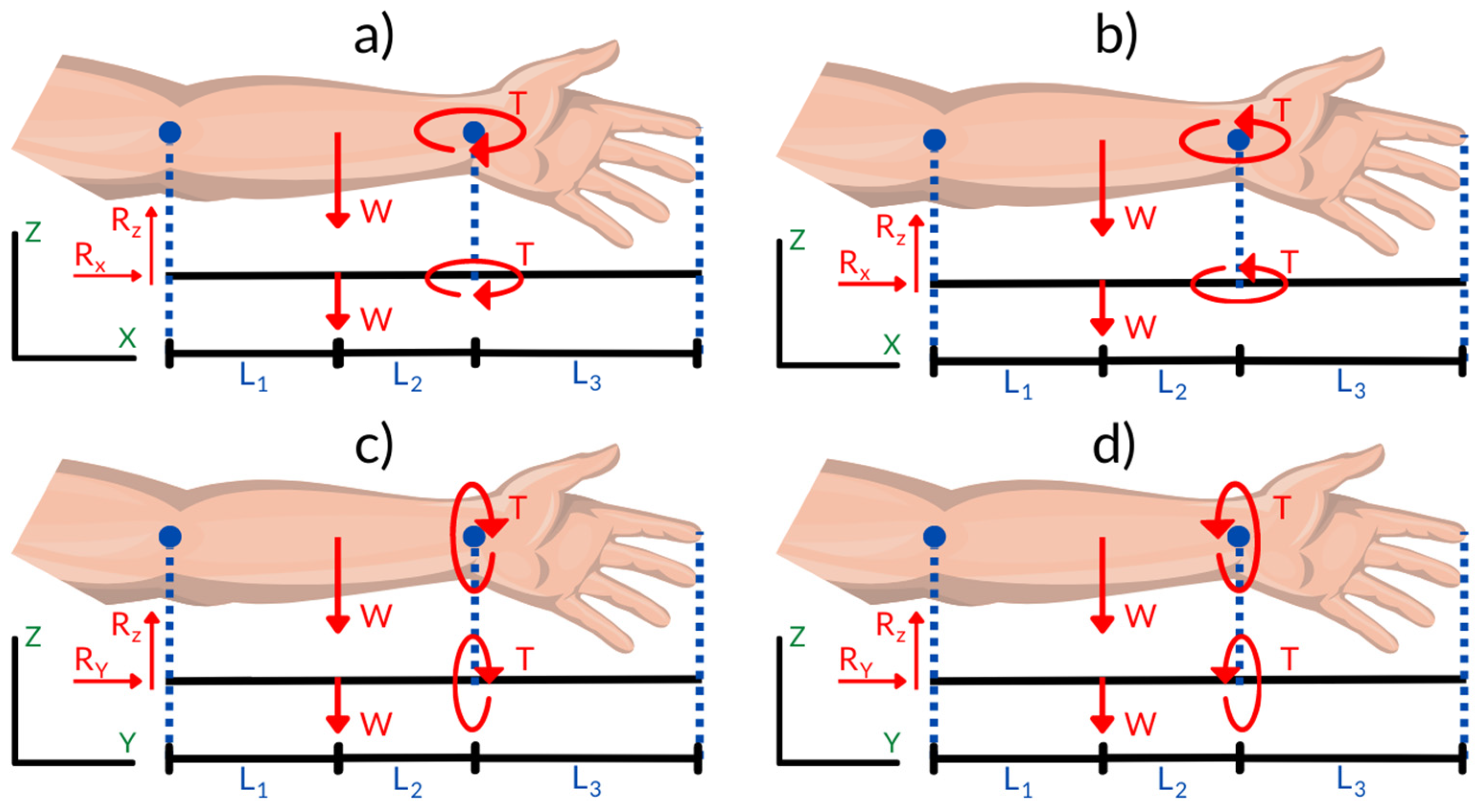
Figure 1 presents the specific values that were considered to evaluate torque, as well as the application and direction of the loads distributed on the forearm. These values are fundamental to understanding how the orthosis will behave in real-life use situations. Torque refers to the tendency of a force to rotate an object around an axis, and in the case of orthoses, it is crucial that torque is kept within acceptable limits to avoid further injury. The application and direction of loads are also important aspects, as an appropriate distribution of forces can help minimize stress on joints and surrounding tissues, thus promoting more effective recovery.
By considering the weight of the orthosis and its material through an MCDM approach, the design was optimized to ensure that the orthosis is not only functional but also comfortable and safe for the patient. The information presented in
Figure 1 shows the factors that interact and affect orthotic performance in the context of forearm rehabilitation.
2.2. Multicriteria Selection Methods and the Weighting Method
COPRAS, VIKOR, TOPSIS, and ENTROPY are the MCDM methods that were used, which are explained below.
2.2.1. Entropy Method
Entropy measures the uncertainty or disorder in information and is rooted in probability theory. In many MCDM methods (like AHP, TOPSIS, VIKOR, etc.), weights are needed to reflect how important each criterion is. Often, those weights come from expert judgment (which can be biased or inconsistent). Entropy provides a data-driven way to assign weights objectively, using the actual decision matrix. Wang et al. developed the Entropy method in [
41].
It is essential to understand the specific methodology associated with each MCDM technique. A critical aspect of this process is the classification of decision criteria as either beneficial (positive) or non-beneficial (negative). This distinction significantly influences the outcome of the decision-making process and must be clearly defined before applying any method.
Table 3 presents the classification of each criterion. This reference was consistently used across all MCDM methods that require such a distinction.
2.2.2. COPRAS Method
The COPRAS method selects the best decision alternatives by considering the ideal and worst-ideal solutions. Unlike methods based on distance (like TOPSIS), COPRAS calculates scores based on the proportional contribution of each criterion to the overall performance. It gives a utility degree for each alternative, making it easier to understand how much better one option is compared to others. Goswami et al. developed the algorithm in [
42].
2.2.3. VIKOR Method
The VIKOR method determines the optimal solution as the solution closest to the ideal one. VIKOR is designed to find a solution closest to the ideal but still acceptable to all parties. Instead of looking for a perfect outcome (which might not exist), it seeks a balance—a compromise among the criteria. Radovanović et al. developed the VIKOR method in [
43].
2.2.4. TOPSIS Method
TOPSIS is based on the concept that the chosen alternative should have the shortest geometric distance from the positive ideal solution (PIS) and the longest geometric distance from the negative ideal solution (NIS). After calculating distances, it gives a relative closeness score (between 0 and 1). Alternatives are then ranked based on how close they are to the ideal. This makes it easy to compare options and justify decisions. Taherdoost et al. developed the TOPSIS method in [
44].
2.3. Simulation by CAD
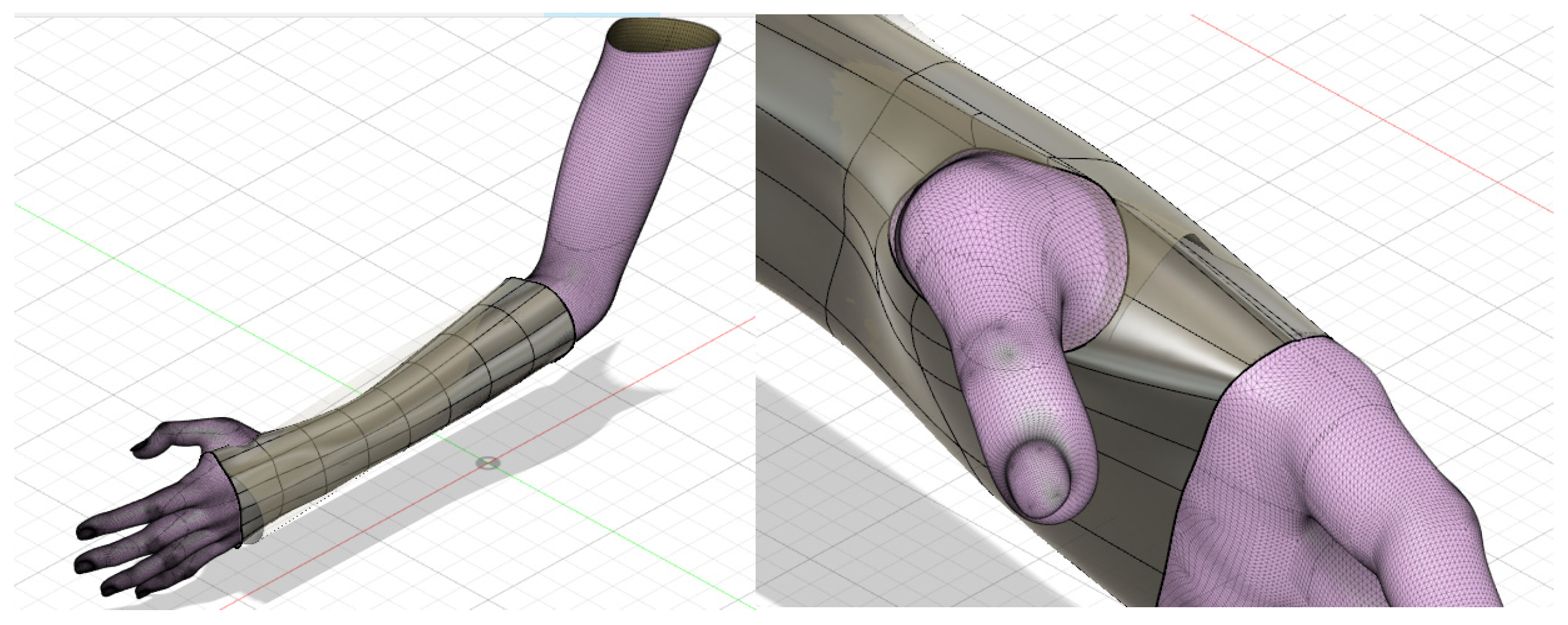
The CAD (Computer-Aided Design) model of the forearm was obtained through a 3D scanning process, applied specifically to the left arm of a 14-year-old woman [
45]. This method allowed the precise capture of the dimensions and anatomical characteristics of the forearm, generating a three-dimensional digital replica that served as the basis for the custom design of the orthosis. For the development of the orthosis, Fusion 360 software was used, which is an advanced tool that facilitates the creation, modification, and analysis of three-dimensional models. From the scanned model, the external surfaces of the forearm were taken as a reference, which allowed for defining a base geometry that fit the specific shape of the limb.
Once the initial geometry was established, said structure was assigned a uniform thickness of 2 mm, guaranteeing a balance between mechanical resistance and lightness for the comfort of the user. An offset of 2–3 mm was applied to the imported mesh. This was necessary to create an adaptation space between the hand and the inner surface of the orthosis in order to avoid discomfort. In order to improve the functionality and mobility of the design, a strategic hole was implemented in the section corresponding to the thumb. This hole was carefully limited to areas of direct contact with the palm of the hand, facilitating finger movement and allowing for an adequate range of flexion and extension, thus contributing to the ergonomics of the device. The precise distribution and location of this hole can be observed in
Figure 2, where its integration into the final design of the orthosis is graphically detailed. According to Bologna et al. [
45], who completed a mesh convergence analysis, first-order tetrahedral elements were used (mesh size of 2 mm).
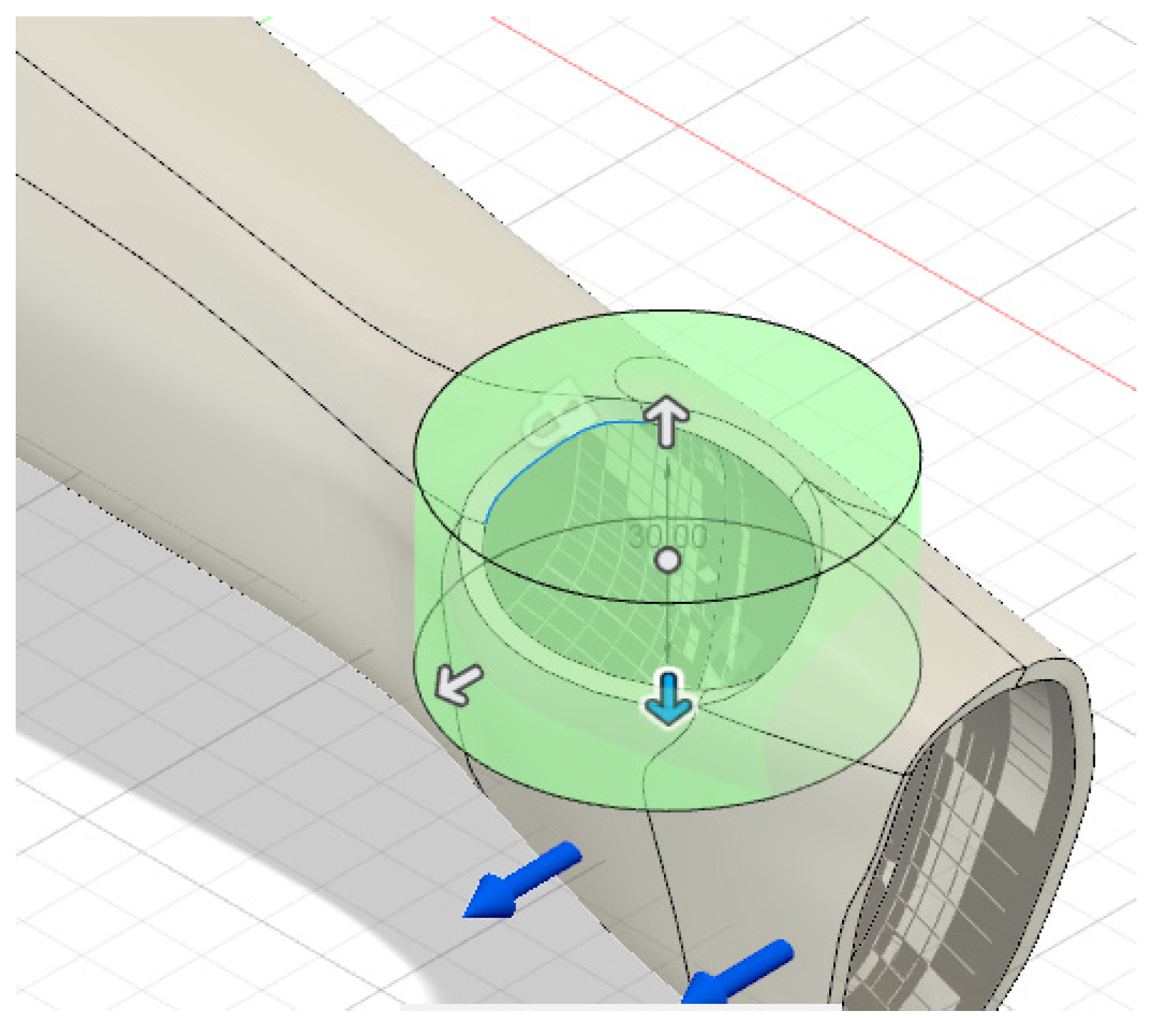
To carry out the simulation of the orthosis, the values of the maximum torques associated with each of the movements performed by the wrist, such as flexion, extension, and radial and ulnar deviation, were taken into account. These values, which are essential to guarantee a functional and resistant design, are presented in detail in
Table 1, serving as a reference to analyze the forces and moments that the orthosis must withstand during use.
As part of the design process, a topological optimization was implemented, which is a technique that allows for reducing excess material without compromising the structural strength of the device. To create the holes, a topological optimization of the design was performed. The topological analysis again considered the four movements generated by the wrist, taking into account the torque generated for the respective reduction in the material that will not be involved during its operation. During this optimization, cavities were generated strategically distributed along the length of the orthosis, with the aim of improving ventilation, offering greater comfort to the user, and avoiding the accumulation of heat and humidity on the skin. The criterion used was to minimize the weight of the prototype, maintaining adequate structural rigidity and ensuring a minimum safety factor equal to or greater than 2 in all the critical movements studied (flexion, extension, abduction, and adduction). The “Shape Optimization” tool in Fusion 360 software was used, with specific restrictions to preserve the material in critical areas, such as the thumb region and attachment zones, thus avoiding compromising the structural and functional integrity of the orthosis. The optimal distribution of the removed material was automatically determined based on the stress distribution generated by the specific torques applied in each condition analyzed.
Additionally, to maintain the mechanical and functional stability of the design, a specific restriction was imposed on the reduction in the material in the section corresponding to the wrist. This area, being a key point for the support and adjustment of the device, requires greater resistance to withstand dynamic loads during movement. The distribution of cavities and restricted areas can be observed more clearly in
Figure 3, where the final result after applying topological optimization is displayed.
3. Results
The results of the orthosis material selection are based on a comprehensive evaluation that combines multicriteria analysis and simulation outcomes. The multicriteria analysis considers various factors, such as mechanical properties (strength, flexibility, and durability), weight, biocompatibility, and cost-effectiveness, to identify the most suitable material for the orthosis. Additionally, the simulation results provide insights into how each material performs under realistic conditions, including stress distribution, deformation, and overall structural integrity. By integrating these two approaches, the material selection process ensures that the final choice balances functionality, comfort, and durability, ultimately enhancing the orthosis’s performance and user experience.
3.1. MCDM Results
3.1.1. Entropy Method Results
The values of the physical, economic, and mechanical properties of the candidate materials, as listed in
Table 1, served as the foundational data for constructing the standard decision matrix. This matrix plays a crucial role in the material selection process, as it organizes and quantifies each material’s attributes—such as density, strength, flexibility, cost, and other relevant characteristics—in a structured format. The decision matrix was then used to perform the normalized decision matrix that was used to calculate the MCDM results, which is expressed in
Table 4.
The results of the Wj calculation are listed in
Table 5. In relation to weights, elongation was given a higher weighting compared to the other criteria. This greater influence is justified by the crucial role played by the flexibility of the material since the orthosis must allow and adapt to the natural movements of the arm and wrist. A material with an adequate elongation capacity guarantees not only the user’s comfort but also the correct functionality, avoiding excessive restrictions that may limit joint mobility [
46].
3.1.2. COPRAS Method Results
The weighted normalized decision matrix (Dij) was computed by multiplying the weight of each criterion—determined using the Entropy method—with the corresponding values in the normalized decision matrix. The resulting values are presented in
Table 6.
The weighted normalized decision matrix (Dij) was calculated by multiplying the weight of each criterion, as determined by the Entropy method, with the corresponding values in the normalized decision matrix. The resulting matrix is presented in
Table 7.
The normalized weight values determined for the beneficial (
and non-beneficial (
) criteria are listed in
Table 8.
The relative priorities of the alternatives (
) are listed in
Table 9.
The performance index (
) values of each alternative are listed in
Table 10.
3.1.3. VIKOR Method Results
The normalized initial decision matrix (fij) values are listed in
Table 11.
The results obtained indicate that, once again, the PLA material is the optimal choice of the six candidates, as can be seen in
Table 12.
3.1.4. TOPSIS Method Results
The TOPSIS method was developed from the vector normalization that involved the quadratic summation of the roots of the materials, as shown in
Table 13.
Then, standardization was carried out from the weights obtained, as shown in
Table 14.
Consequently, the evaluation of ideal and non-ideal solutions was carried out, as shown in
Table 15.
Finally, the distancing indices were determined, which are represented in
Table 16.
The effect of modifying the weights of the criteria on the final decision was analyzed. To achieve this, the weight of each criterion was increased and decreased by 10%, and it was observed that the order of the alternatives did not change significantly. Since the alternatives maintained their order despite changes in weights, the model is robust [
47].
3.2. Simulation Results
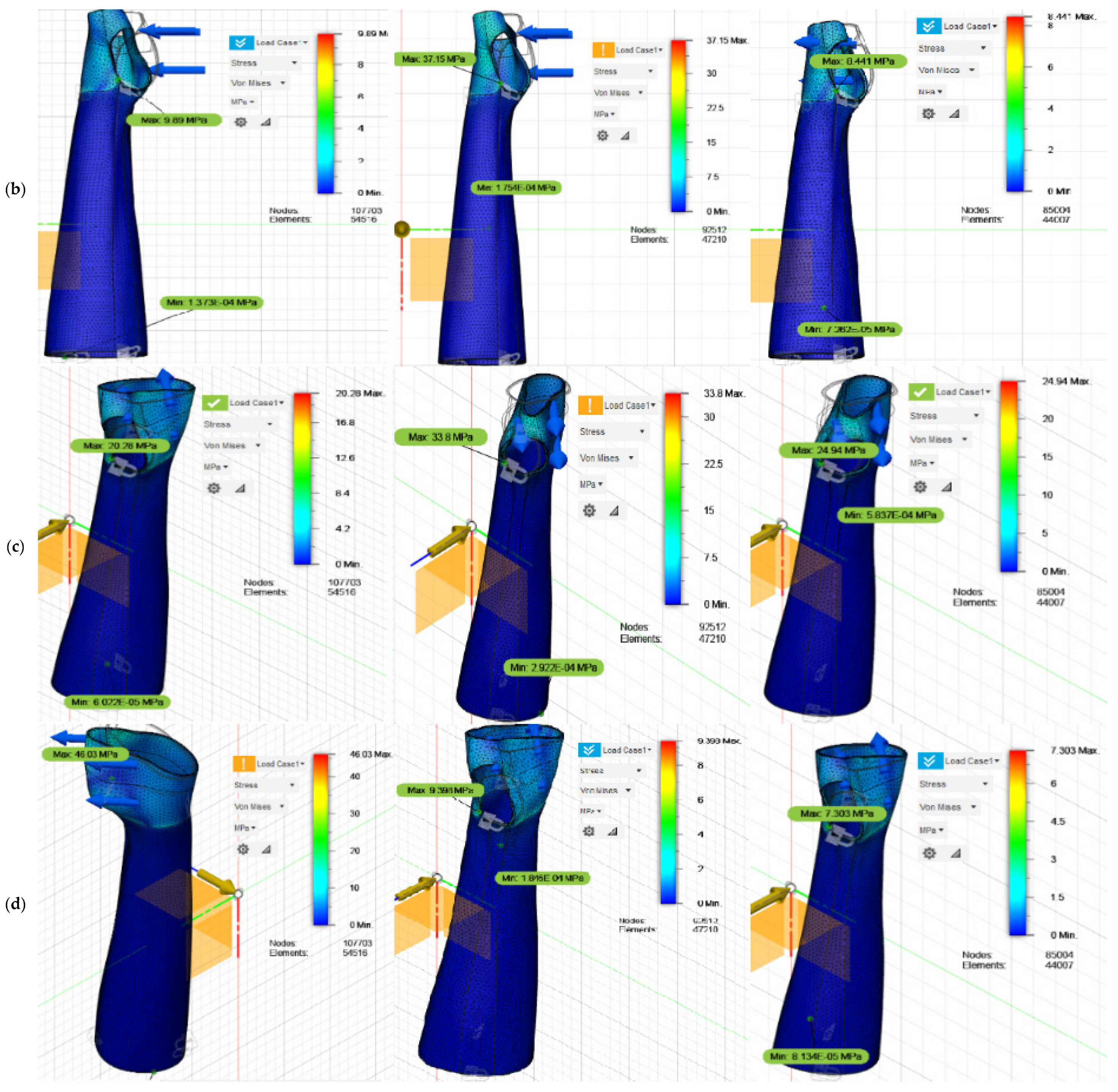
Four static analyses were carried out to evaluate the structural design of the orthosis, considering two key factors: the torque applied in the forearm–wrist–hand interaction and the weight of the selected material. In this case, PLA was chosen through the MCDMs selection. The objective of these analyses was to ensure that the orthosis could withstand the expected mechanical loads during use, guaranteeing both its strength and functionality.
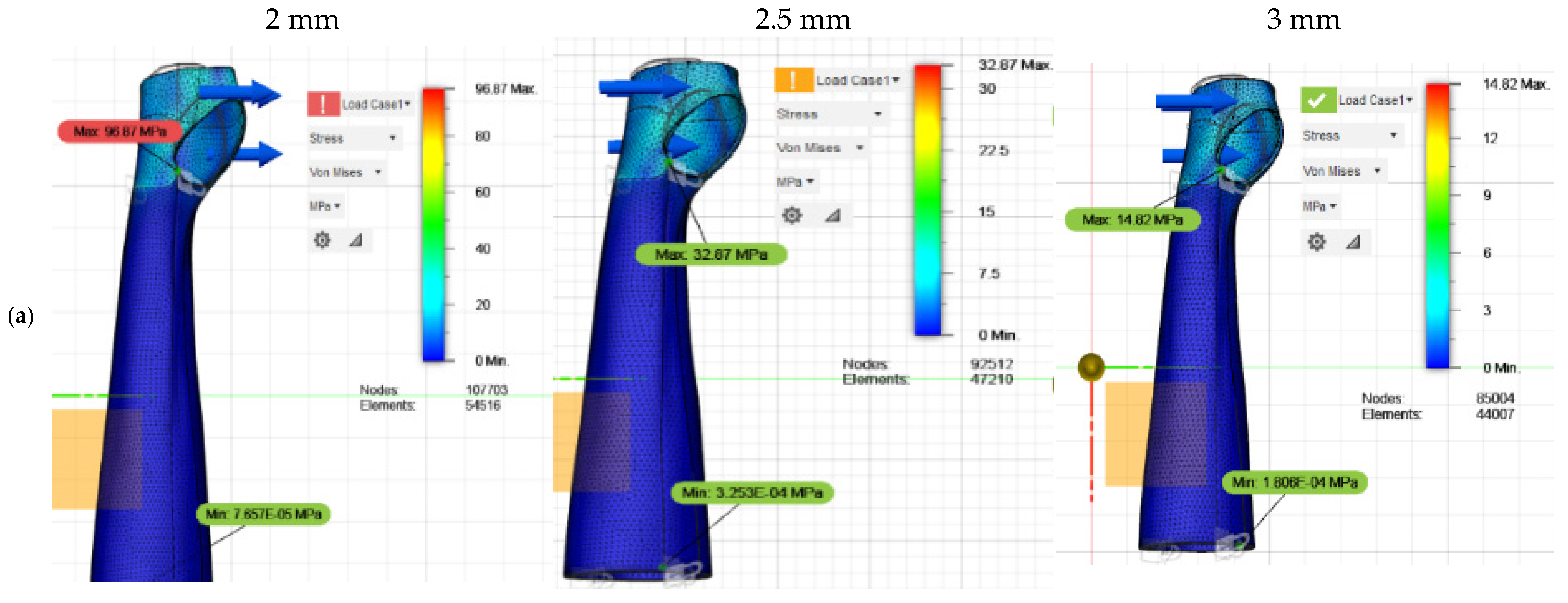
The detailed results of the stress distribution for each of the analyzed movements are presented graphically in
Figure 4 and clearly summarized in
Table 17, providing a quantitative and visual overview of the mechanical performance of the final design. The safety factor was calculated using Fusion 360 software by dividing the ultimate strength of the selected material (PLA with a strength of 32.8 MPa) by the maximum stress obtained in the structural simulations. This value takes into account the most critical local conditions generated in each simulated scenario.
For the simulations, a thickness of 2 mm was initially assigned to the CAD model of the orthosis. However, the results revealed that the maximum stress recorded in the flexion, extension, and abduction movements exceeded the ultimate stress of the PLA, set at 32.81 MPa. Given these results, the thickness of the design was increased to 2.5 mm, but the analyses continued to show stress values very close to the maximum limit of the material, implying a risk of structural failure under certain critical conditions.
In response to these observations, the thickness was finally adjusted to 3 mm, thus achieving a significant improvement in the mechanical behavior of the device. In this configuration, the values obtained remained within a safe range, with the most critical case being the abduction movement, with a maximum recorded stress of 24.32 MPa. Furthermore, the resulting deformations were acceptable for each of the evaluated scenarios, guaranteeing an adequate structural configuration for the orthosis.
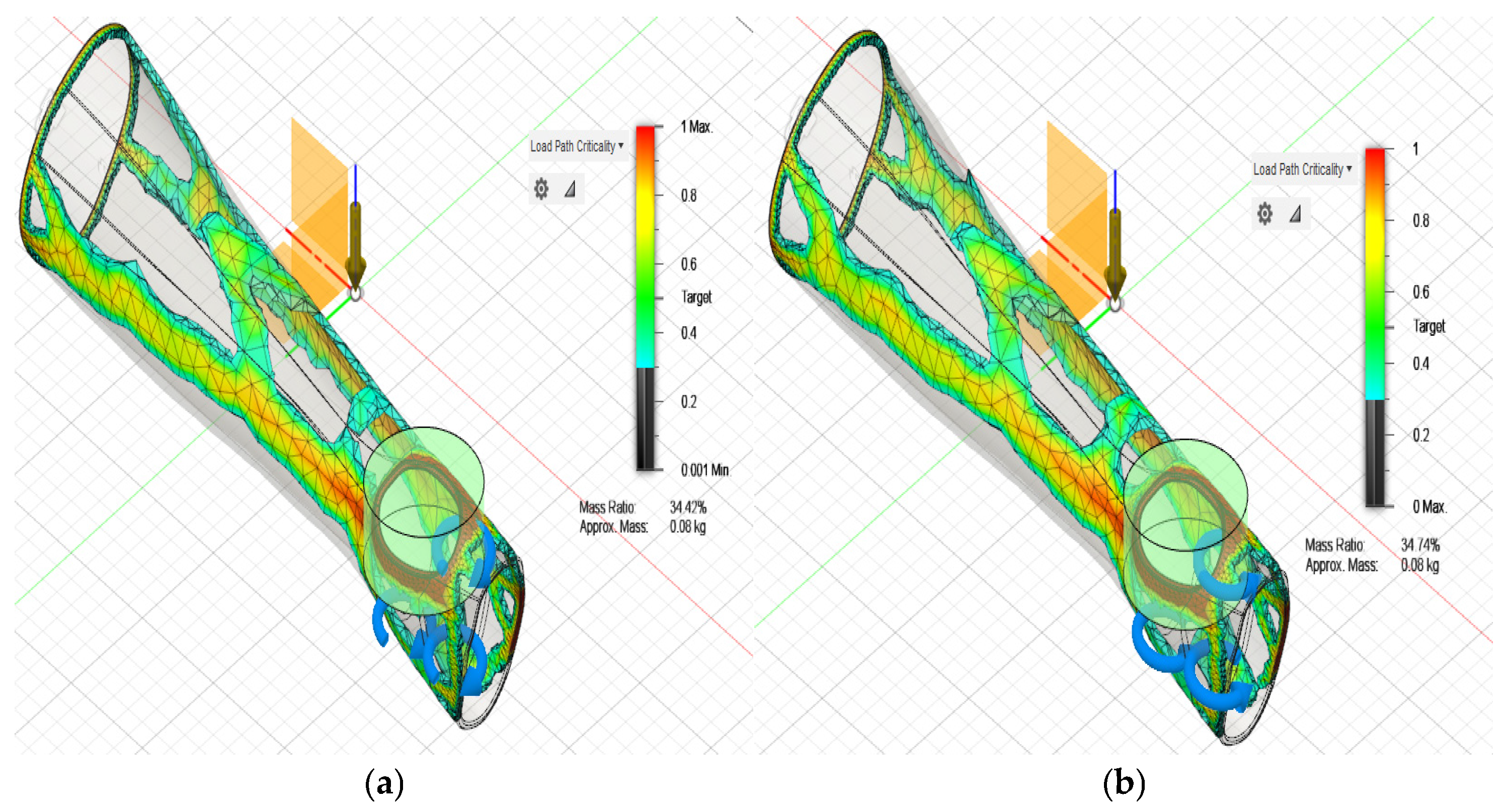
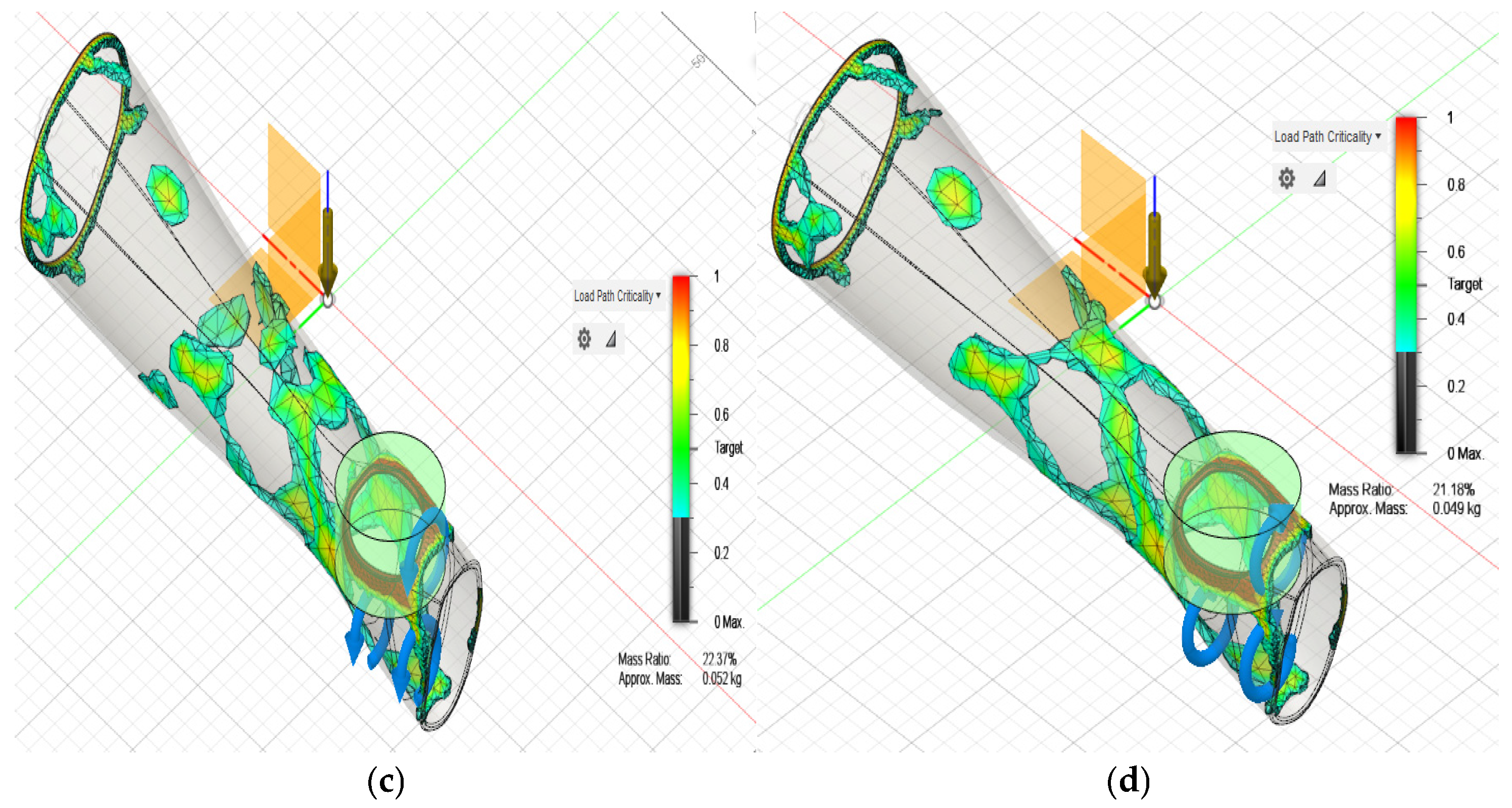
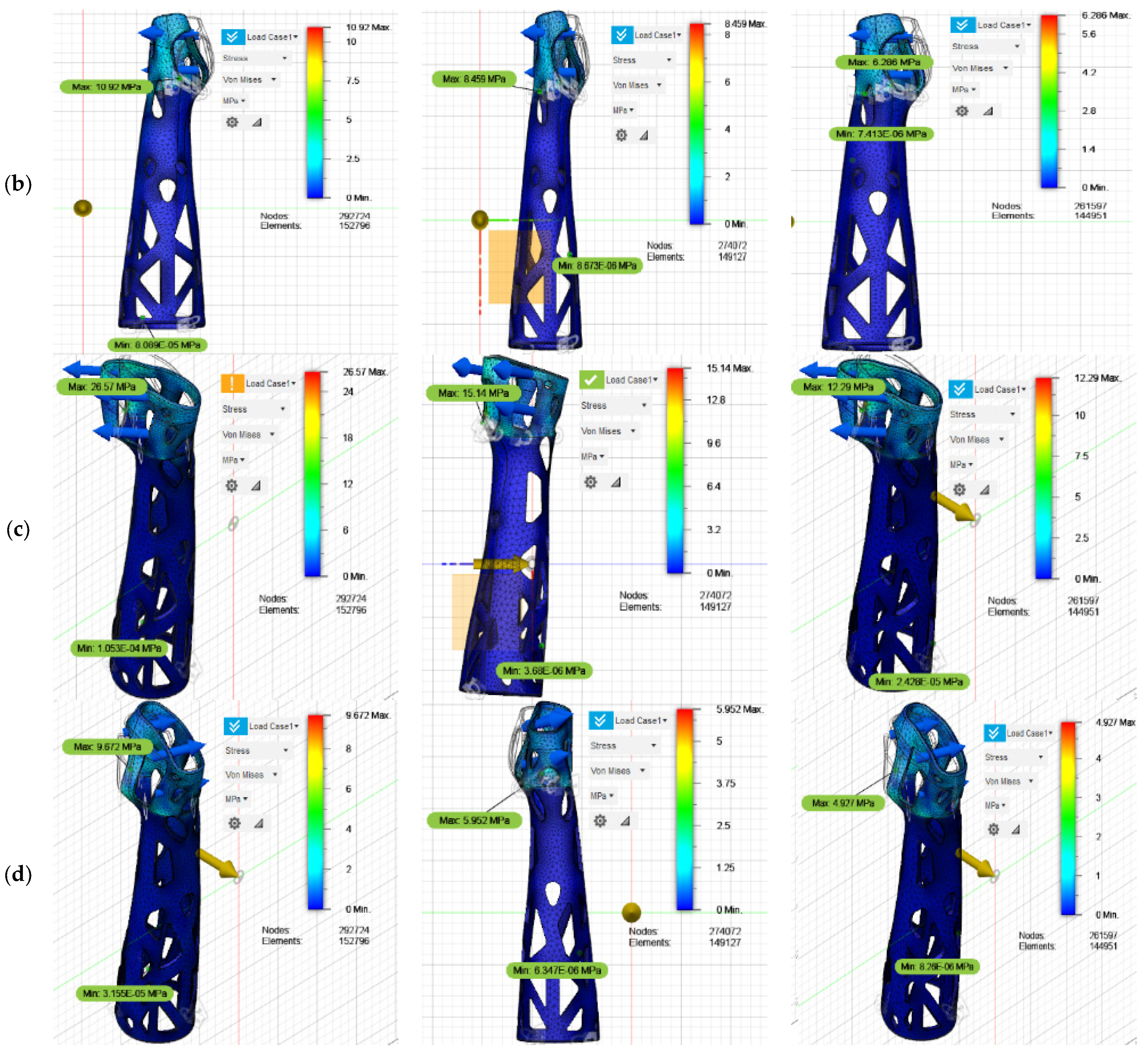
The results obtained from the topological optimization performed for a thickness of 3 mm indicate that when subjecting the orthosis to typical flexion, extension, abduction, and adduction loads, different percentages of the original mass are retained in the structure, depending on the direction of the applied load. Specifically, under the conditions of flexion, extension, abduction, and adduction, the mass remaining in the orthosis is reduced to 34.42%, 34.51%, 22.37%, and 21.18%, respectively. These results indicate a significant reduction in the material in the orthosis, especially in areas where the load is lower and where further optimization can be allowed without compromising structural integrity.
The analysis reveals that the areas experiencing the greatest reduction in material correspond to the section of the forearm close to the elbow and the dorsal area of the hand. These areas, which are not critical for structural strength under the applied loads, can withstand a reduction in material without negatively affecting the performance of the orthosis. Based on these findings, it was decided to combine the results obtained from each of the studies carried out in order to achieve an optimized solution that combines efficiency in the use of the material with the guarantee of functionality and comfort for the user. The preliminary optimization model obtained is presented in
Figure 5, which illustrates how the reduced mass is distributed along the optimized structure.
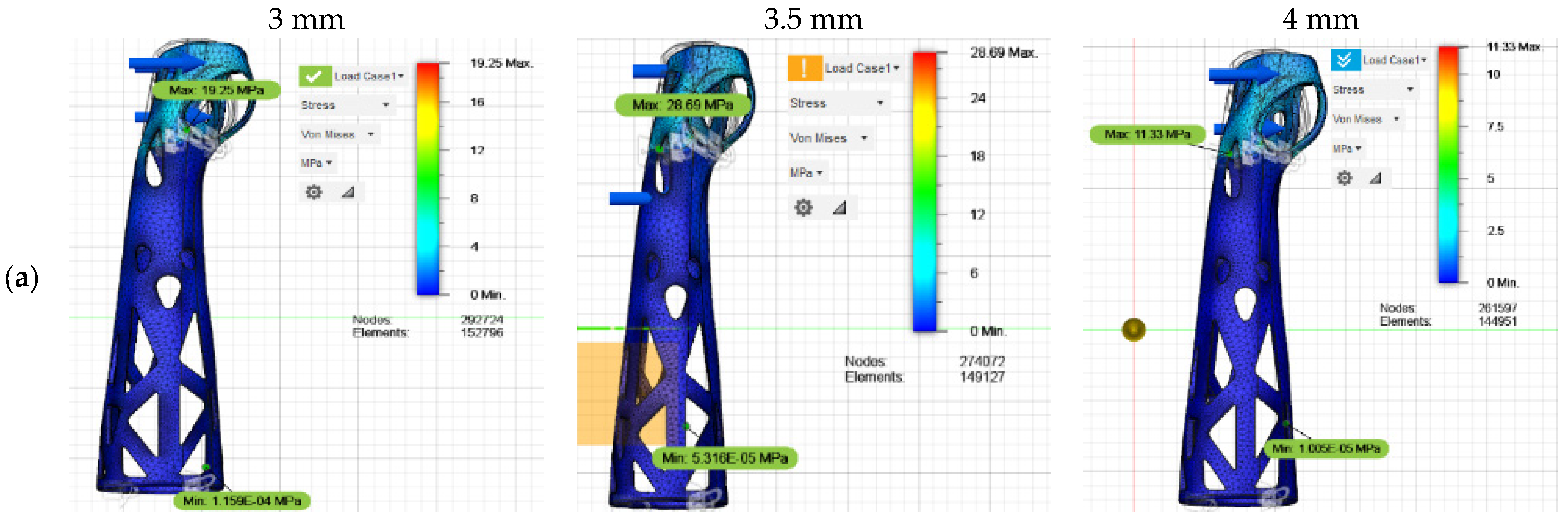
With the preliminary model of the orthosis, a static analysis was performed again to evaluate its behavior under the intended conditions of use, considering the relative movements of the arm during typical activities. The main objective of this analysis was to verify the structural resistance of the new geometry obtained based on the loads and stresses to which the orthosis will be subjected. For an initial thickness of 3 mm, the results show that the orthosis is within the limit ranges of acceptable stresses and deformations. However, when analyzing in detail the behavior of the orthosis in the abduction movement, it is observed that the stresses reach values close to the ultimate stress, which could compromise the structural integrity of the orthosis in situations of maximum load.
Given this situation, it was decided to adjust the thickness of the orthosis to ensure greater safety in its performance. A thickness of 3.5 mm was chosen, which improves resistance, but when performing a new analysis, it was determined that under the flexion movement, the orthosis does not comply with the minimum safety factor required to ensure its reliability and durability in real use. Therefore, it was decided to increase the thickness to 4 mm. With this adjustment, a stress distribution was obtained that remains within the admissible values for the new geometry, ensuring increased safety and optimal performance in all arm positions during movement. The detailed stress distribution results for each of the optimized cases are presented in
Figure 6 and concisely summarized in
Table 18.
It was determined that, through the optimization process, a significant reduction in the original mass of the design is achieved. The mass is reduced from 0.313 kg to 0.283 kg, which represents a reduction percentage of 9.58%. This decrease in weight is crucial, as it directly contributes to improving the ergonomics of the orthosis, allowing greater comfort for the user without compromising its functionality. This mass reduction value is significant for the application of the orthosis, as lightening the weight improves the patient’s experience when using it, especially in terms of comfort during prolonged periods of use.
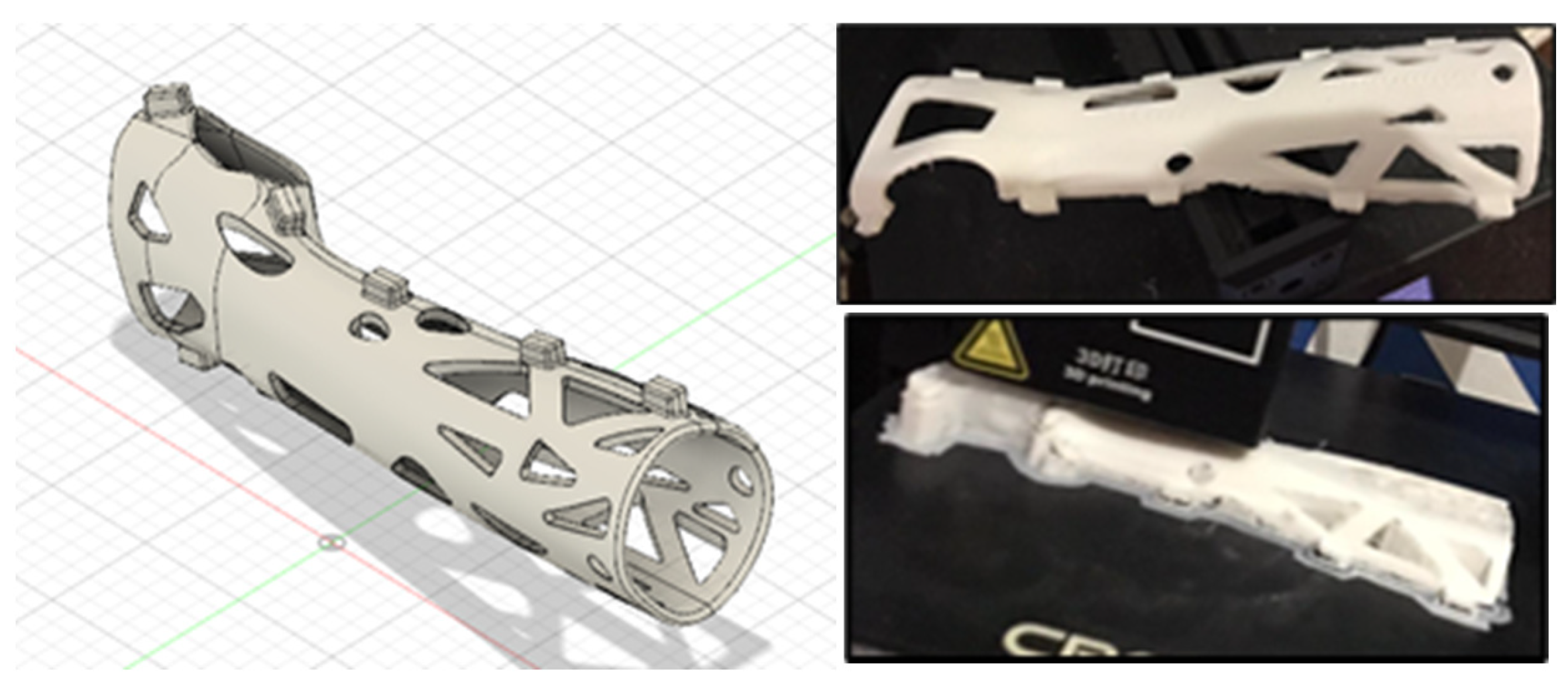
Additionally, the obtained model was subjected to a refinement treatment, focusing on its edges to eliminate any possible discomfort that may be generated when coming into contact with the skin. This was achieved by rounding the edges, which not only improves the aesthetics of the design but also the safety and well-being of the patient. Furthermore, the orthosis was divided into two pieces to facilitate its placement and adjustment on the patient’s arm, incorporating connecting elements between both parts to ensure that the orthosis remains firm and comfortable during use.
With these adjustments and improvements, the achieved orthosis is not only functional and efficient but also easier to apply, ergonomically adapting to the user’s anatomy. Finally, after completing all the necessary modifications, the CAD model was 3D-printed, obtaining the optimized version of the orthosis according to the considerations and improvements detailed in this study, as illustrated in
Figure 7.
4. Conclusions
In this study, various plastic materials were evaluated with the aim of identifying those that present mechanical characteristics comparable to plaster, which is traditionally used in the manufacture of orthoses. Using MCDM, specifically, TOPSIS, VIKOR, and COPRAS, it was determined that the most suitable material for the design of orthoses is PLA. The coincidence in the results obtained through these three methods reinforces the reliability of the selection of PLA as the ideal material, by balancing essential properties such as strength, flexibility, and light weight.
Additionally, a computer simulation was carried out to validate the structural performance of the orthoses designed with PLA. The results showed that a thickness of 4 mm in the orthoses intended for adolescents meets the structural and geometric requirements necessary to guarantee stability, rigidity, and compression capacity, essential for the effective immobilization of the forearm. Likewise, through a topological analysis, a mass reduction of 9.75% was achieved with respect to the original design, without compromising the mechanical properties of the device. This optimization not only contributes to reducing the overall weight of the orthosis, which increases user comfort, but also facilitates its prolonged use during the recovery process.
The design and optimization of orthoses have evolved significantly, integrating advanced manufacturing processes, such as 3D printing, and the use of innovative materials. In this context, the present study offers a relevant contribution to future research by providing a solid methodological framework for the selection of materials based on objective criteria and the verification of their behavior through computer simulations. Furthermore, this approach could be extended to adapt to different anthropometric measurements of patients with low-impact fractures, ensuring that orthoses are not only functional but also personalized and ergonomic. The use of these emerging technologies allows for progress towards more efficient, lightweight medical devices adapted to the specific needs of each patient, thus promoting a more effective and comfortable recovery.
A clinical benefit for patients is weight reduction. A lighter orthosis reduces fatigue, improves comfort, and enhances mobility during recovery, which are especially important for elderly patients with low-energy fractures. Other benefits include the improved anatomical fit (via topology optimization), improved immobilization, and reduced pressure points, which lead to fewer complications like pressure sores, better healing alignment, and improved compliance with wearing the orthosis. Furthermore, the use of PLA, a non-toxic, lightweight, customizable material that enhances comfort and allows for personalization, can positively affect patient satisfaction and potentially accelerate recovery.
In addition, our 3D-printed orthosis provides economic advantages, including cost-efficiency. It has the potential for lower production costs with desktop 3D printing, especially in low-resource settings. Furthermore, rapid production and customization can reduce time to treatment. Finally, the topological optimization process ensures efficient use of PLA, minimizing waste and cost.
Limitations and Future Studies
This study focused on the forearm of a woman between 10 and 14 years old. However, it could be replicated for other populations. Future studies could include a more extensive and diverse population to validate our findings across different groups. These studies may also include orthoses for other parts of the body, such as parts of the leg or ankle.
While the simulation results provide a solid foundation for understanding the mechanical behavior of the orthotic component, it is crucial to recognize the gap that often exists between computational predictions and real-world performance. Finite element analysis (FEA), although powerful, inherently involves assumptions and simplifications—such as ideal boundary conditions, uniform material properties, and static loading—that may not fully capture the complexities of real-world use. In practice, factors such as material anisotropy due to 3D printing orientation, layer adhesion variability, and long-term fatigue under cyclic loading can influence the actual durability and comfort of the orthosis.
Furthermore, anatomical and biomechanical variability among users introduces an additional layer of complexity. Differences in foot geometry, weight distribution, gait patterns, and pathology severity can all affect how forces are transmitted through the orthotic device. The loading conditions used in the simulation, while representative, are based on a standardized model and may not encompass the range of scenarios encountered in daily use. Incorporating parametric studies or probabilistic design approaches could enhance robustness by accounting for a wider spectrum of anatomical and functional profiles. Additionally, future work could benefit from integrating personalized anatomical data (e.g., from 3D foot scanning) to validate and refine the current design for broader clinical applicability.
Three multicriteria methods were used for result validation, but more methods could be used.


