Abstract
Rapid progress in lithium-ion batteries and AI-powered autonomous driving is poised to propel electric vehicles to a 50% share of the global automotive market by the year 2035. Today, there is a major focus on recycling electric vehicle motors, particularly on extracting rare earth elements (REEs) from NdFeB permanent magnets (PMs). This research is based on a single-furnace process concept designed to separate metal components within PM motors by exploiting the varying melting points of the constituent materials, simultaneously extracting REEs present within the PMs and transferring them into the slag phase. Thermodynamic modeling, via Factsage Equilib stream calculations, optimized the experimental process. Simulated materials substituted the PM motor, which optimized modeling-directed melting within an induction furnace. The 2FeO·SiO2 fayalite flux can oxidize rare earth elements, resulting in slag. The neodymium oxidation reaction by fayalite exhibits a ΔG° of −427 kJ when subjected to an oxygen partial pressure () of 1.8 × 10⁻⁹, which is lower than that required for FeO decomposition. Concerning the FeO–SiO2 system, neodymium, in Nd3+, exhibits a strong bonding with the matrix, leading to its incorporation within the slag as the silicate compound, Nd2Si2O7. When 30 wt.% fayalite flux was added, the resulting experiment yielded a neodymium extraction degree of 91%, showcasing the effectiveness of this fluxing agent in the extraction process.
1. Introduction
Technological innovation, the growing need for environmental protection, and the ongoing economic transformation have all contributed to the remarkably rapid advancement in electric vehicle (EV) development over the past ten years. The market is trending toward fully electric vehicles because of the continuous advancements in lithium-ion battery technology, which have led to extended EV driving ranges of over 600 km and reduced costs, as shown in studies [1,2]. Furthermore, the development of artificial intelligence-powered systems for EVs, crucial to the advancement of the 4th Industrial Revolution, is anticipated to have a substantial effect, as noted in the literature [3,4]. IHS Markit reported that the global sales of EVs surpassed 17 million units in 2024, a significant market share driven by leading manufacturers such as China’s BYD and NIO, and Europe’s Volkswagen and BMW, as cited in references [5,6,7]. In addition to previous findings, BloombergNEF’s projections indicate that EVs are expected to constitute a significant portion, approximately 50%, of all vehicle sales globally by the year 2035, as noted in reference [8].
EVs rely on the Permanent Magnet Synchronous Motor (PMSM), a remarkably efficient component achieving a coefficient of performance (COP) of up to 97%, providing exceptional power and performance, crucial for vehicle operation. Due to the interaction between the rotor’s constant magnetic field and the stator’s alternating magnetic field, the PM motor operates by generating torque, resulting in a smaller and lighter motor that produces higher power than traditional motors [9,10,11]. Due to the utilization of permanent magnets (PMs), there is a reduction in electrical power consumption, and the conversion of magnetic force into mechanical force is achieved without any mechanical failure or wear and tear. NdFeB, a powerful PM material, consists of a blend of 29–32% Nd, 64–66% Fe, and 1–2% B, plus minor amounts of rare earth elements (REEs) such as Dy, Nb, Ga, and Tb for improved performance characteristics [12,13,14]. The rotor has the PMs embedded within its structure. Both rotor and stator utilize non-grain-oriented (NGO) electrical steel, also known as silicon steel (1–4% Si), laminated with sheets measuring between 0.35 and 0.5 mm [15,16,17]. Electrical steel, with its high permeability, is designed to minimize the loss of magnetic energy and to ensure that magnetic flux flows efficiently. The stator, positioned externally to the rotor, produces an alternating magnetic field which subsequently causes the rotation of the rotor, a phenomenon described in detail within the literature [18,19,20]. The cylindrical stator, a multi-layered structure made from electrical steel sheets, features slots within its design that contain the copper wire conductors. High-purity copper constitutes the copper wire. The motor housing protects the stator and rotor from mechanical damage, water ingress, dust, and other environmental factors, while also managing heat dissipation during operation. In selecting housing materials, several factors are taken into consideration, including but not limited to weight, cost, thermal conductivity, and durability, with aluminum alloys being the typical choice. ADC12, A356, 6061-T5, 6082-T6, and 7075-T6 represent the most commonly employed alloys for EV motor housings [21,22].
As EVs progress through their lifecycles, the process of recycling their PM motors is increasingly recognized as a critical aspect requiring attention and innovation. Many studies demonstrate the significant economic advantages of recycling copper, aluminum, and REEs from PM motors, especially because this process recovers scarce resources such as neodymium and other REEs from discarded permanent magnets. The studies by Zushi et al. [23], Tiwari et al. [24], Chang et al. [25], and Mitrouchev et al. [26] collectively contribute to our understanding of how waste electric motors can be disassembled into their individual components, with a particular focus on the contributions of robotic systems to this complex and important process. While the detailed disassembly process is successful in achieving a high recycling efficiency of 99%, the wide range of designs and sizes of PM motors found in EVs, as well as their widespread application in electric tools, water pumps, computers, cooling systems, and washing machines, hinders its effectiveness. PM motors of EV commonly contain roughly 2 kg of PM [27,28]. Numerous techniques for REE extraction have been investigated when the elements are separated, encompassing methods such as pyrometallurgy, which utilizes high temperatures, hydrometallurgy, which involves aqueous solutions, bioleaching, a process leveraging microorganisms, and electrochemical processes that utilize electrical currents to facilitate separation. The research conducted by Katsunori et al. [29] involved the process of melting the rotor with PM to extract rare earth elements (REEs) into RexOy-Na2B4O7 slag, while Saito et al. [30] focused on the study of dissolving REEs in Nd2O3–B2O3 slag. Moreover, Yang et al. [31] investigated REE extraction using CaO–SiO2–Al2O3 slag and pointed out that subsequent hydrometallurgical processes are essential for enabling REE recovery.
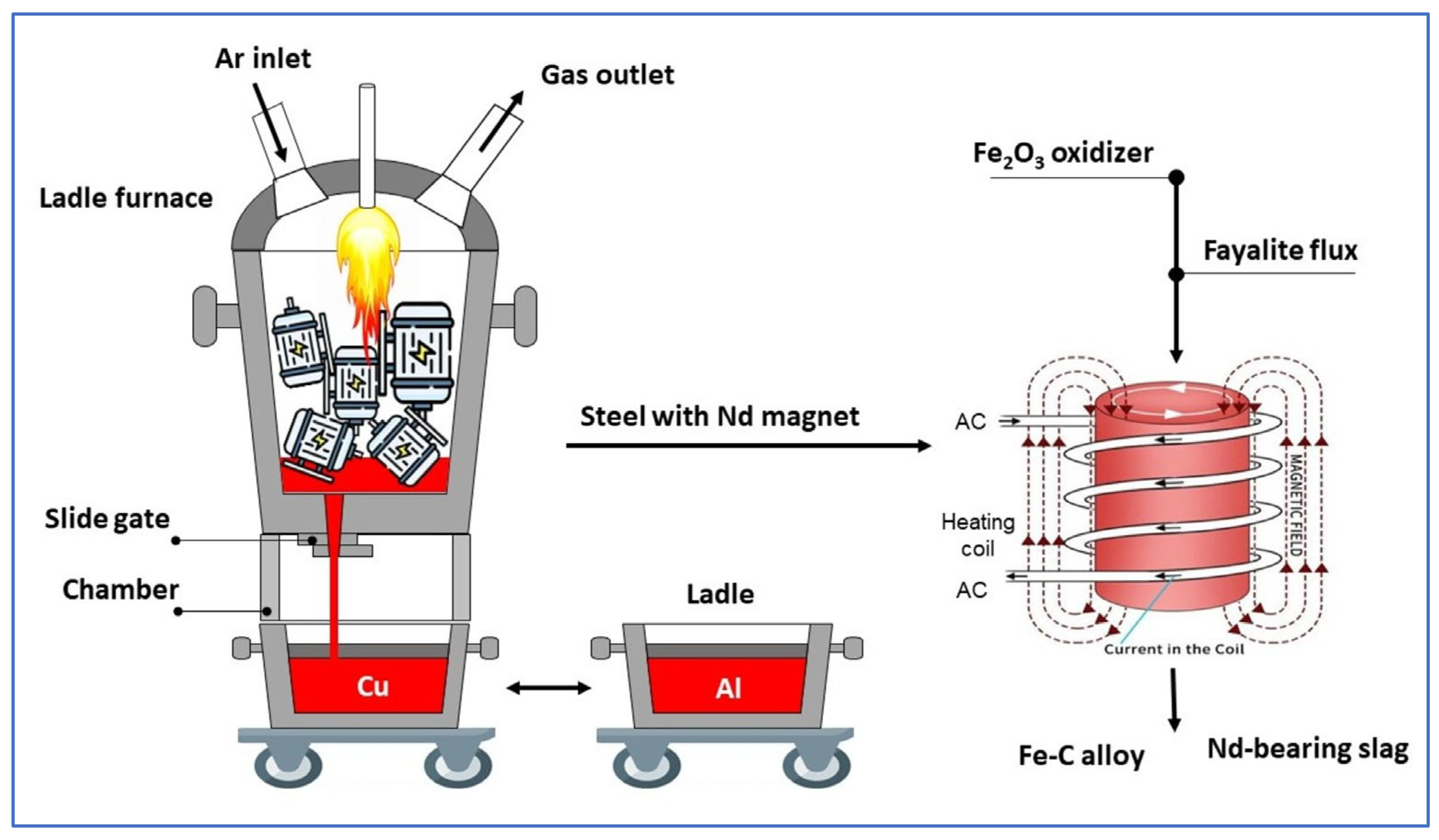
Our research is conceptually based on a straightforward, high-temperature, single-furnace technique that leverages the disparate melting points of metallic materials—aluminum (~700 °C), copper (~1100 °C), and steel (~1600 °C)—found within PM motors of EV, allowing for the separation of these metals while simultaneously extracting rare earth elements (REEs) into slag. In the melting process, the NdFeB magnet fully melts with the rotor steel, combining in Fe liquid; the strong oxidation potential difference in REEs causes their oxidation and subsequent transfer to the slag, facilitating selective separation. Scheme 1 provides a general overview of the research. This study utilized the Factsage program to design optimized models and simulations of steel and PM material processing at a high-temperature, following the separation of aluminum and copper, and concluding with smelting tests conducted in an induction furnace. The utilization of a synthesized fayalite flux (Fe2SiO4) as a dual-functioning material, acting as both an oxidizer and a slag former, represents a significant new development within the context of this research on REE recovery. During this process, Fe2SiO4 serves as an oxidizer; simultaneously, free , released from fayalite, engages in a reaction with REEs to form their silicates, these silicates then becoming constituents of the slag. The innovative use of fayalite-based slag from copper smelting in this study offers a novel approach to this research, while simultaneously supporting the important concept of sustainable material technology. The slag, which contains the compound RexOy, serves as the raw material input for the subsequent stages of hydrometallurgical processing. Hydrometallurgical method for REE recovery from NdFeB magnets, as reported in studies [32,33,34], usually consists of oxidative roasting followed by selective leaching (H2SO4 and HCl), yielding > 99% recovery efficiency. Yan et al. [35] confirmed the presence of REEs in the CaO–SiO2 slag system as Ca2RE8(SiO4)6O2 and achieved a 99% recovery with an HCl solution, whereas Blenau et al. [36] achieved a 94% recovery from the CaO–Al2O3–Nd2O3 slag system using an H2SO4 solution. Moreover, Ziyan et al. [37] showed that over 99% of REEs can be recovered from roasted REE salt electrolytic slag with H2SO4 solution. Throughout the various hydrometallurgical studies conducted, an oxidizing agent was introduced to the REEs solution, facilitating the conversion of REEs into oxide precipitates which were then separated, ultimately resulting in the production of pure RexOy oxides as the final product. In our research, the next crucial step involves employing a hydrometallurgical approach to effectively recover REEs that are present within the slag.

Scheme 1.
Using a single furnace, the different metal materials (~700 °C for Al, ~1100 °C for Cu, ~1600 °C for Fe) of a PM electric motor can be separated according to their melting points. While metals of the NdFeB magnet melt and dissolve with Fe, the strong oxidation of REEs facilitates their separation from liquid Fe using Fe2SiO4 to oxidize. The reaction between RexOy and SiO2 yields silicates that are incorporated into the slag. During smelting, Fe2SiO4 functions as both an oxidizing agent and a slag-forming substance.
2. Materials and Methods
2.1. Experimental Materials
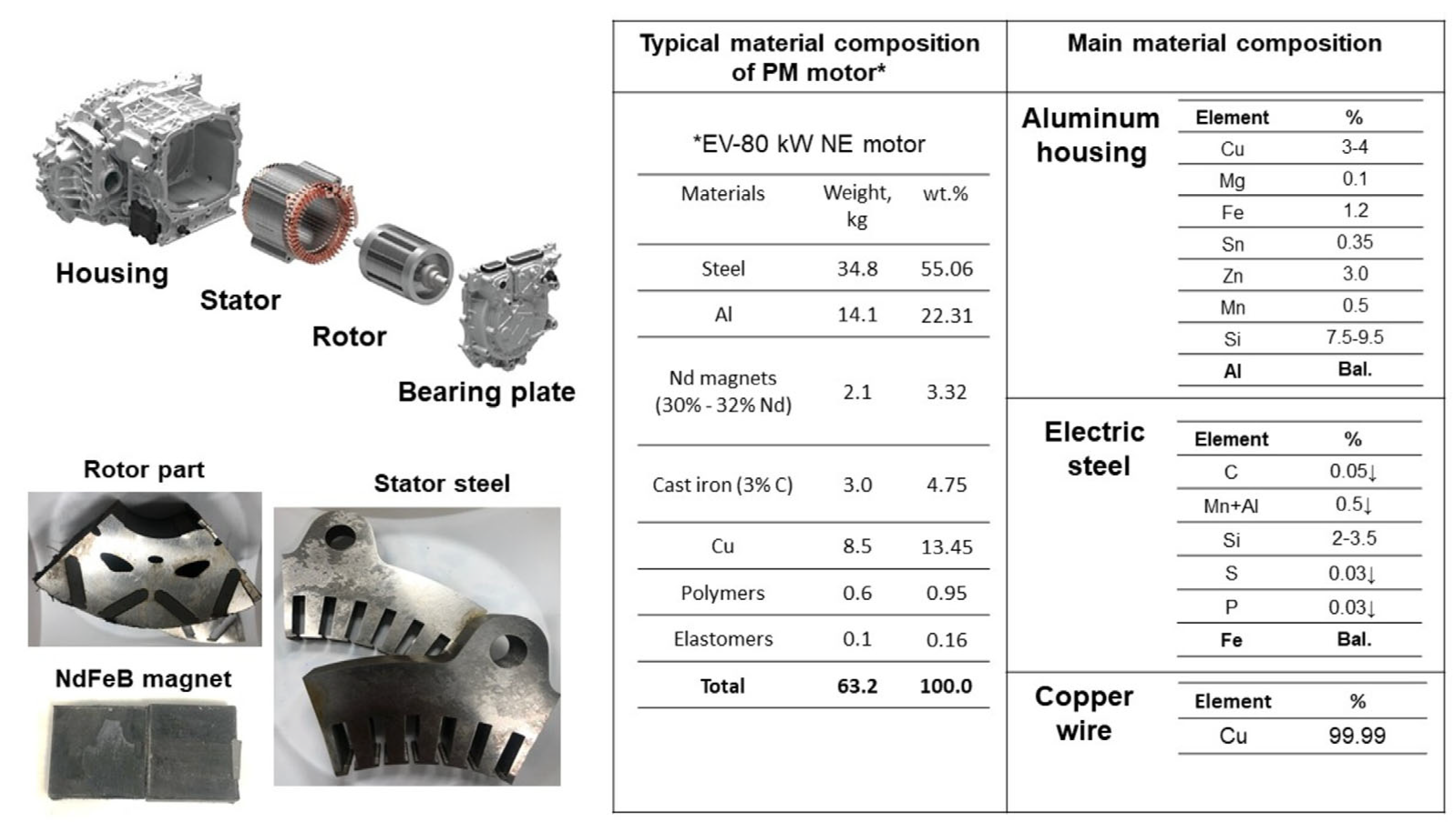
In preparation for the experiment, a water jet cutting machine was utilized to section the stator and rotor components of an EV-80 kW NE PM synchronous motor into numerous pieces. Individual removal of copper wires from the stator facilitated isolation of the steel. In addition to the other preparatory steps, the PMs were carefully separated from the rotor parts so that the magnetic materials could be prepared for the material balance. Shown in Figure 1 are the weight percentages of the constituent materials of the PM motor, as adopted from Elwert et al. [38] and Bast et al. [39], with a further breakdown provided of the chemical compositions for its key components, including the aluminum housing, electrical steel, and the copper wires used within the motor’s construction. Material inputs were adjusted in this experiment according to the PM motor’s weight percentages. In the construction of the PM motor, a 6063–T5 aluminum alloy is employed for the housing (as cited in references [40,41]), whereas the electrical wiring consists of high-purity copper, ensuring efficient electrical conduction. The core components as stator and rotor which are constructed from electrical steel—a material prized for its superior magnetic properties and minimal energy loss, as evidenced in studies [42,43]. Electrical steel (silicon steel) includes 2–6% silicon, <0.05% C, ≤0.5% Mn + Al, and <0.03% S and P. Electrical steel pieces (PM motor stator and rotor) and NdFeB magnets (30% Nd), shown in Figure 1, comprised our experimental materials.
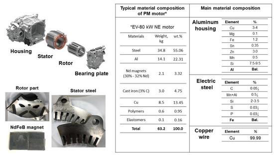
Figure 1.
Typical material compositions of EV–80 KW PM motor.
In the smelting process for electrical steel, a temperature ranging from 1600 to 1650 °C is necessary, a temperature range also utilized in the production of low-carbon steel. As the carbon content in an Fe-C alloy increases, a corresponding decrease in its melting temperature is observed. Following this principle, this experiment employed cast iron flakes as a carburizing agent to decrease the melting temperature of the steel. The chemical composition of the cast iron flakes, as analyzed via Optical Emission Spectrometry (OES), is detailed in Table 1. This includes an approximate concentration of 3.5% carbon, 2.6% silicon, 0.34% phosphorus, and 0.13% sulfur. For analyzing neodymium in the Fe-C alloy from NdFeB magnets, we confirmed the absence of neodymium in the cast iron.

Table 1.
Chemical composition of cast iron flakes analyzed by OES.
Based on data from Elwert [38], and making the assumption that aluminum housing and copper wire are separable due to their comparatively low melting points, the input material balance for the simultaneous smelting of electrical steel and PMs was calculated using weight percentages, and the resultant data are presented in Table 2. The EV-80 kW PM motor has a total mass of 63.2 kg. The material input was calculated to determine that it consisted of 87.2 wt.% electric steel, 5.26 wt.% NdFeB magnets, and 7.52 wt.% cast iron after calculating the weight percentages of the remaining steel and magnetic materials.
Table 2.
Material balance calculation for Fe-C alloy and magnet smelting.
In the smelting process, synthetic fayalite flux used as both a slag former and an oxidizer. A 70:30 mixture of FeO and SiO2 powders underwent synthesis at 1200 °C. The synthetic fayalite flux, crushed to under 10 mm, was prepared. The synthetic fayalite flux underwent XRF analysis to determine its chemical composition, as shown in Table 3. The Al2O3 oxide is likely from the alumina crucible. MgO and Cr2O3 are among the impurities that may be responsible for the high sensitivity in XRF analysis.
Table 3.
Chemical composition of synthetic fayalite flux by XRF analysis.
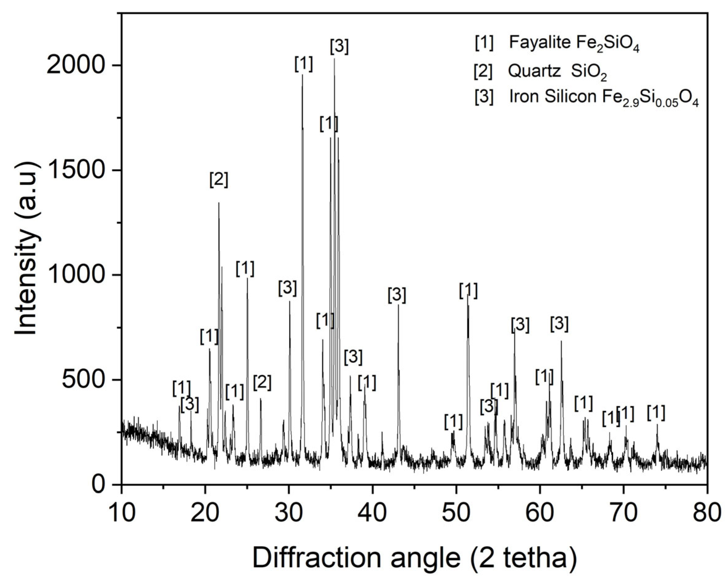
The XRD mineralogical analysis results for the synthetic fayalite flux are presented in Figure 2. Analysis confirmed fayalite, predominantly formed from FeO and SiO2, with the iron silicate compound Fe2.9Si0.05O4 also present. Unreacted FeO and SiO2 are indicated by the presence of SiO2 phases. However, this flux’s processing at high temperatures during steel and magnet smelting is unlikely to cause any problems.
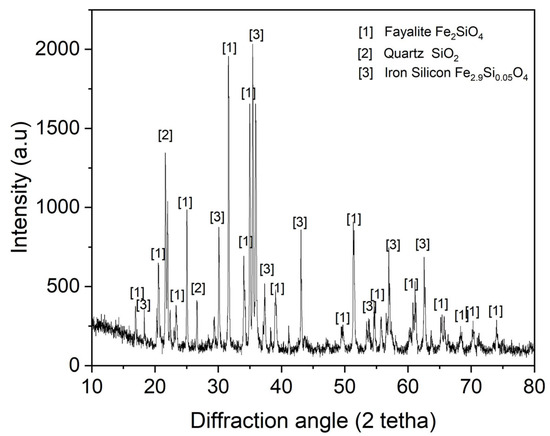
Figure 2.
XRD pattern of synthetic fayalite flux.
2.2. Experimental Procedure
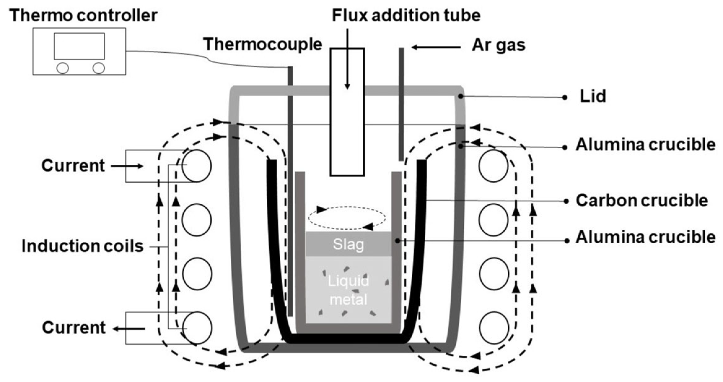
A 10 KW, 30 KHZ high-frequency induction furnace was utilized to perform the experiment. Figure 3 schematically illustrates the experimental apparatus. Samples were put into an alumina crucible inside a graphite crucible. A graphite crucible was used as the heater. A thermometer sat between graphite and alumina crucibles, insulated by surrounding Al2O3 powder. This method may not accurately measure the liquid metal’s temperature, but it usefully prevents the furnace temperature from dropping below 1550 °C during adjustments. Programming settings on an NP200 model thermo-controller regulated installed the induction furnace used in the experiment. A lid with channels for argon gas injection and extra materials sealed the furnace chamber. To protect the graphite crucible from combustion, 300 mL/min of Ar gas was supplied throughout the heating and cooling process. After the experimental materials fully melted, a 30 min hold was implemented. Oxidizer and flux agents were then added sequentially at 10 min intervals, completing the experiment. The furnace was heated gradually and steadily at a rate of 20 °C per minute to 1550 °C and maintained there. The sample, cooling in the furnace at 20 °C per minute, reached room temperature before removal. The induction furnace included a cooler, controller, and heater. Voltage regulation in the high-frequency induction melting furnace ensured the desired temperature for optimal melting.
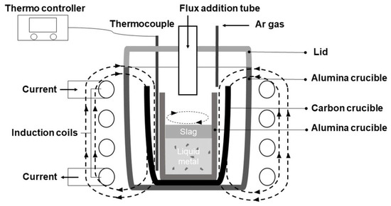
Figure 3.
Schematic diagram of the experimental apparatus.
2.3. Analytical Methods
2.3.1. Thermodynamic Modeling
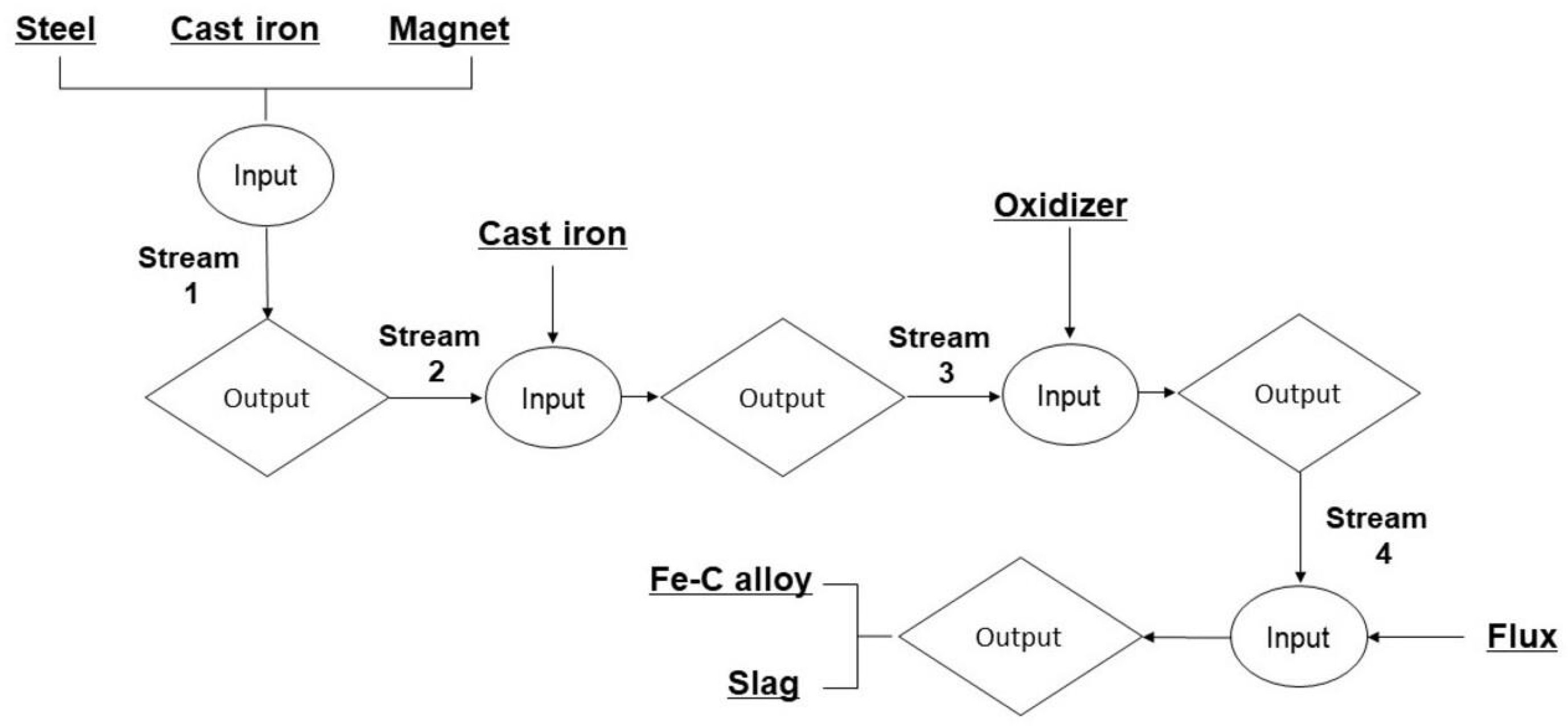
For this particular study, the thermodynamic modeling process was carried out with the utilization of the specialized software package known as Factsage 8.2. The FactSage Equilib module, a powerful tool in thermodynamic analysis, was employed to calculate material balances and determine equilibrium smelting conditions, ensuring a comprehensive understanding of the process. Multiphase, multicomponent equilibrium material data can be inputted using the Equilib module. Within the simulation, materials were saved as outputs from one stream and then used as inputs for the next processes to conduct computations. The stream flow chart for smelting simulation calculations is shown in Figure 4. As an illustration, in the first stream of the modeling, the materials utilized—electrical steel, cast iron, and NdFeB magnets—underwent preliminary modeling based on their constituent chemical compositions, as shown Table 1 and Table 2, and Figure 1. A 100 g input specifically guided the preparations; the melting simulation used equilibrium conditions of 1600 °C and 1 atm. Using the output from the stream as input for the following process, a similar methodology was followed, allowing for the continuation of calculations. In the final thermodynamic analysis, the oxidation of neodymium during the smelting was assessed by examining the Gibbs free energy change, the heat of the melting reaction, and the activity of the products, with the amount of added fayalite flux influencing the oxidation process.
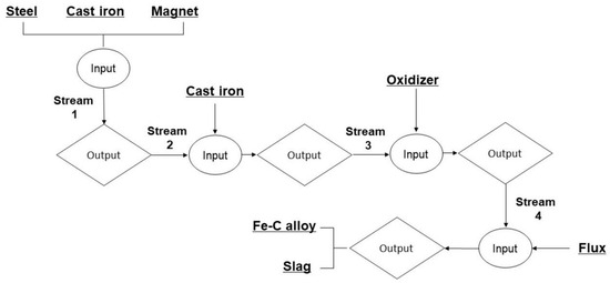
Figure 4.
Flowchart for calculating stream equilibrium.
2.3.2. Calculating Neodymium Recovery Degree
The recovery degree was crucial in determining the effectiveness of neodymium extraction from NdFeB magnet through smelting. A calculation was performed to compare the neodymium mass within the magnet prior to the smelting procedure with the neodymium mass that was associated in the slag following the completion of the smelting process. Equation (1), which is shown below, is used to represent the degree to which nickel is recovered (η):
where Mslag is the slag weight, g, Mmagnet is the magnet weight, g.
2.3.3. Chemical and Mineralogical Analysis
To determine the chemical composition of the flux and slag, a Shimadzu XRF-1800 model X-ray fluorescence spectrometer, manufactured by Shimadzu Co., Ltd in Japan, was employed, yielding highly accurate data. Inside the XRF machine, the sample was carefully placed in a platinum crucible before being loaded into the machine. The X-Ray Diffractometer, specifically the model X’Pert-MPD PANalytical, featuring a high-intensity 3 kW Cu-Kα X-ray tube, was instrumental in determining the mineral composition of the flux and slag. A scanning range of 10 to 80° was employed for the XRD data collection of the nickel ore, with a time of 10 min and a step size of 0.02°. The model used for analysis in this study was the EM-30AX, manufactured by COXEM Co., Ltd in South Korea, a Scanning Electron Microscope and Energy Disperse X-ray Spectrometer (SEM-EDS) which allowed for a comprehensive examination of the inclusion morphology in the metal and the distribution of its elements. A detailed analysis using the Inductively Coupled Plasma Optical Emission Spectrometer (ICP-OES), specifically the Agilent 5800 ICP-OES model of Agilent Technologies Inc in USA, was conducted to precisely ascertain the content of neodymium. The composition of the Fe-C alloy was determined through the use of an advanced analytical technique which involved employing a high-precision Bruker brand advanced model Q4 TASMAN–170 Series 2, manufactured by Bruker Co., Ltd in Germany, spark-optical emission spectrometer (OES) instrument. In preparation for OES analysis, the sample surface was meticulously polished using 600–grit sandpaper, rinsed thoroughly with ethanol, and then carefully air-dried. For the analysis, the sample was carefully and symmetrically placed within the confines of the spark stand to ensure accurate results. This study utilized the mean result from three examinations.
3. Results and Discussion
3.1. Thermodynamic Modeling of Steel and Magnet Smelting
As detailed in Table 2, the material composition for the input was determined to be 87.2 wt.% electrical steel, 7.52 wt.% cast iron, and 5.26 wt.% NdFeB magnet, following which the material balance calculation using the Equilib mode was executed. Based on chemical composition, input materials were liquid-state Equilib stream outputs processed at 1600 °C. Table 4 shows the chemical compositions and input proportions of electrical steel, cast iron, and NdFeB magnets.
Table 4.
Input material composition in Equilibrium stream–1 calculation.
The output composition from Equilib stream–1 modeling of a homogeneous Nd-bearing Fe-C alloy liquid (produced from electrical steel, cast iron, and magnet at 1600 °C) is shown in Table 5. Calculations showed the metal materials produced a homogeneous liquid weighing 99.8 g, despite 0.197 g of solid NdS. The sulfur that was introduced with the neodymium transitioned into a sulfide solid phase, coming from the cast iron. In the Fe-C liquid, the chemical composition reveals a carbon content of 0.3 wt.%, a silicon of 2.81 wt.%, a neodymium of 1.41 wt.%, and the presence of other impurity elements. Over 90% of the neodymium mass remains in the liquid metal.
Table 5.
Output product composition in Equilibrium stream–1 calculation.
The metal liquid output of the Stream–1 process, an Fe–C liquid containing only 0.3% carbon, is categorized as low-carbon steel due to its low carbon concentration. Low-carbon steel production usually involves a processing temperature approximately 100 °C higher than its melting point, necessitating the use of extremely high temperatures ranging from 1600 °C to 1650 °C. Because increasing the carbon content of an Fe–C alloy lowers its melting point, as is fundamentally understood, increasing the carbon in the Fe-C liquid will; therefore, reduce the melting temperature. This approach enables a lower temperature for the smelting experiment. The addition of cast iron to increase the carbon content of Fe–C alloy has advantages; the relatively low melting point of cast iron (~1400 °C) creates a liquid phase that accelerates the melting process for electrical and magnetic steels. Table 6 presents the alteration in carbon content and other elements within the Fe–C liquid from Stream–1, resulting from the addition of cast iron. The Stream–2 input used the same initial cast iron in the Equilib stream calculations. With the addition of 10 wt.% of cast iron, the carbon content within the liquid Fe–C liquid exhibited a rise, reaching a final content of 0.59%. Increasing the carbon content lowers the melting temperature of the Fe–C alloy, but this is counteracted by an increased liquid metal mass and higher energy consumption. Additionally, the sulfur introduced with the cast iron, which contributes to NdS formation, was considered. Therefore, in the Equilib Stream–2 modeling, achieving a carbon content of 1% was deemed sufficient. The condition with an additional 30 wt.% cast iron was considered optimal for this experiment, and the composition of the liquid outputs is shown in Table 6. In this case, the Stream–2-output-modeled liquid metal mass was 129.59 g, with 0.214 g of NdS solid phase formed. The Fe-C liquid metal contained roughly 80% of the neodymium; calculations suggest the remainder formed a NdS solid solution.
Table 6.
Output product composition on cast iron addition by Equilibrium stream–2 calculation.
A method for roughly estimating the melting temperature of steel, based on the amount of carbon it contains, is presented and explained in Equation (2). Here, the melting point of pure iron is lowered, with the decreasing amount calculated by using the carbon content present in the steel and multiplying it by the constant coefficient [44]. When 30 wt.% cast iron is added to the stream–2 metal liquid, the resultant Fe-C liquid metal exhibits a carbon content of 1%, thereby suggesting a melting point of around 1464 °C. Through optimization, it was determined that increasing the temperature by 100 °C would allow for the successful conduction of the melting experiment.
Tm ≈ 1539 − 75 × (%C), °C
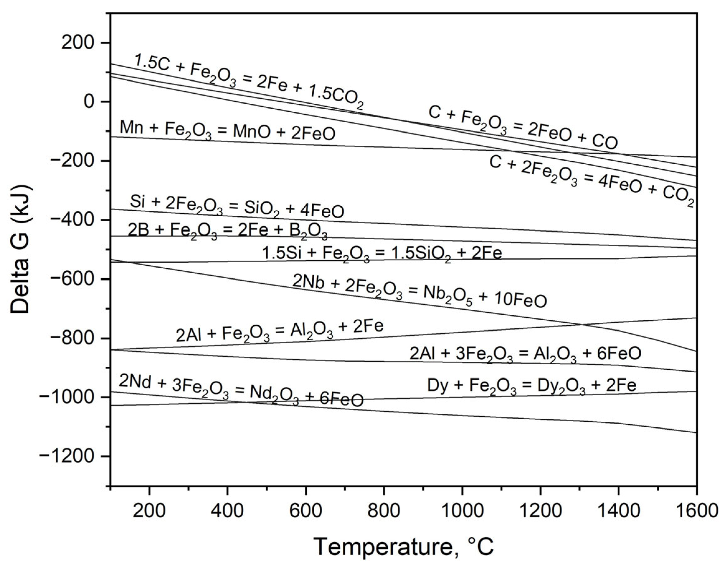
The key objective of this investigation is to successfully separate neodymium and other REEs from liquid metal, a process which hinges on their greater potential for oxidation when compared to iron. Because of its effectiveness and efficiency in oxidation reactions within Fe–C alloy systems, the use of Fe2O3 as an oxidizing agent is highly recommended for the melting process. Equation (30) shows the redox reaction in which REEs undergo oxidation by Fe2O3, concurrently with the reduction of iron, leading to its transition into the liquid metal. As depicted in Equations (4)–(6), the oxidation process impacts a wide array of elements, encompassing not only REEs but also various impurities frequently present in Fe-C liquid—specifically Mn, Si and C—all of which undergo transformation into their respective oxide forms during this process.
[Re](l) + Fe2O3(s) = RexOy−1(s) + [Fe](l)
[Me](l) + Fe2O3(s) = MexOy−1(s) + [Fe](l)
[C](l) + Fe2O3(s) = 2(FeO)(l) + CO(g)
3[C](l) + Fe2O3(s) = 2[Fe](l) + 3CO(g)
Figure 5 shows a comparison of Gibbs free energy changes that result from the oxidation of elements within an Fe–C liquid, utilizing Fe2O3 as the oxidizing agent in the process. At the experiment temperature of 1550 °C, REEs and aluminum demonstrate the most significant oxidation tendencies, as clearly evidenced by their Gibbs free energy values falling below −600 kJ, indicating a strong thermodynamic drive toward oxidation. The presence of Si, Mn, and C within the steel allows for their oxidation, a process resulting in the separation of these elements from the liquid metal, as confirmed by our observations.
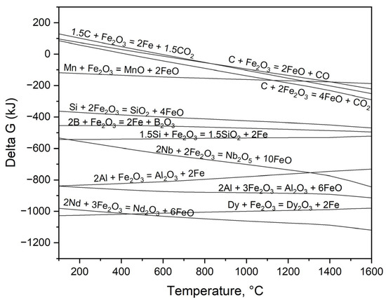
Figure 5.
Gibbs free energy changes for oxidation modeling of the REEs and Fe-C alloy composition under standard equilibrium via HSC Chemistry 6.2.
The Stream–3 calculation, at 1550 °C and with 30 wt.% cast iron, modeled the production of 129.59 g of liquid metal and 0.214 g of solid NdS. Each simulation variant was created by adding the oxidizing agent Fe2O3, increasing by 2 wt.%. The objective was to quantify the Fe2O3 addition needed, considering the mass transfer and oxidation of REEs in the liquid metal. The Stream–3 model’s material balance and liquid steel composition are shown in Table 7. The neodymium content in the liquid metal dropped to 1 × 10⁻⁷% with just a 2 wt.% Fe2O3 addition. Other REEs and Al underwent strong oxidation and separated from the liquid metal. Increasing Fe2O3 additions caused oxidation and removal of C and Si from the liquid metal. Carbon oxidation produced CO gas, which made up 99.8% of the gas released while smelting. Stream–3 modeling showed that 2 wt.% Fe2O3 addition was enough. However, adding a fayalite flux as the slag-forming agent ensured complete oxidation of any remaining unoxidized REEs.
Table 7.
Output product composition on Fe2O3 oxidizer addition by Equilibrium stream–3 calculation.
Fayalite, a compound with the chemical formula 2FeO·SiO2, is characterized by its low melting point and susceptibility to decomposition, and it plays a crucial role as a primary component of the slag formed during the smelting processes of metals like copper and zinc. This study is unique in its utilization of fayalite, which serves the dual purpose of acting as both a slag-forming agent and an oxidizing agent, a distinctive characteristic setting it apart from other similar studies. The oxidation of REEs by FeO within fayalite during the smelting process of electric steel and magnetic materials, from fayalite decomposition, is detailed in Equation (7). Nd and Dy show significant oxidation, evidenced by their ΔG° values of −427 kJ and −452 kJ, respectively. Moreover, Equations (8) and (9) illustrate that impurity elements in the liquid metal, with a greater oxidation tendency than iron, are also oxidizable.
| a[Re](l) + bFe2SiO4(s) = c(RexOy)(s) + d(SiO2)(l) + h[Fe](l) | at 1550 °C ΔG°[Nd] = −427 kJ ΔG°[Nb] = −186 kJ ΔG°[Dy] = −452 kJ | (7) |
| a[Me](l) + bFe2SiO4(s) = c(MexOy)(s) + d(SiO2) + h[Fe](l) | ΔG°[Si] = −219 kJ ΔG°[Al] = −311 kJ ΔG°[Mn] = −97 kJ | (8) |
| a[C](l) + bFe2SiO4(s) = c(CO)(s) + d(SiO2) + h[Fe](l) | ΔG°[C] = −75 kJ | (9) |
Fayalite flux addition in Stream–4 modeling used variable flux amounts. Table 8 shows the material balance and liquid metal composition from modeling Stream–4 output products with fayalite flux. Adding up to 30 wt.% fayalite flux increased the liquid metal mass to over 140 g, but only 2.15 g of slag formed. When slag exceeded 30 wt.%, increased amounts indicated fayalite’s FeO had finished oxidizing role during decomposition. Liquid metal analysis showed complete REE oxidation; they were removed from the metal, forming AlNdO3 and RexO3 oxides. A continuous decrease in carbon content to 0.34% at 30 wt.% preceded the onset of decarburization in the steel. The amount of silicon in the steel also went down. Adding too much fayalite flux has several detrimental consequences for the steelmaking process, namely a significant increase in energy consumption, a substantial rise in slag volume, and a considerable reduction in the carbon content of the resulting steel. Consequently, the addition of a fayalite flux of up to 30 wt.% has been determined to be an adequate amount for the desired outcome.
Table 8.
Output product composition on flux addition by Equilibrium stream–4 calculation.
The chemical composition of the slag output from the Stream–4 modeling is shown in Table 9. Above 30 wt.% fayalite flux additions, slag phases, as noted before, were observed. The slag formation at 30 wt.% flux addition resulted in a composition of 95.8% SiO2; conversely, increasing the weight percentage to 40 wt.% and 50 wt.% flux additions led to a decreasing in SiO2 content to 54.4% and 50.5%, respectively, indicating a clear inverse relationship between weight percentage and SiO2 concentration within the formed slag. In contrast, the FeO content within the slag exhibited a notable increase, reaching 28.17% and 43.1% at the specified levels; this increase serves as a strong indication that the oxidation process impacting the constituents of the liquid metal has concluded.
Table 9.
Output slag composition on flux addition by Equilibrium stream–4 calculation.
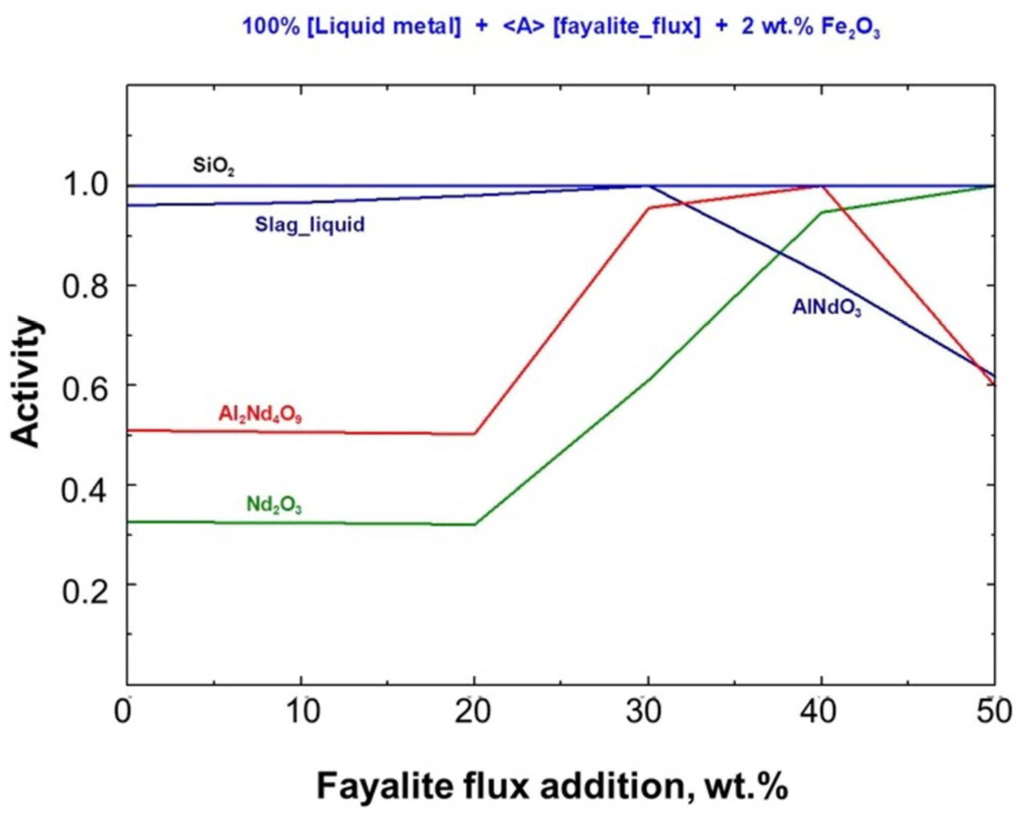
A thermodynamic analysis of the Stream–4 model for smelting with fayalite flux was performed, considering Gibbs free energy changes, reaction heat, and the activity of the resulting products. The relationship between product activities and the amount of fayalite flux added is shown in Figure 6, which offers a detailed comparison. The level of fayalite flux directly impacts the activity of solid oxides and slag, without considering the liquid metal. When liquid slag activity reached unity at 30 wt.%, the AlNdO3 solid phase activity decreased. Conversely, the RexO3 oxide activity rose, as seen in the figure below.
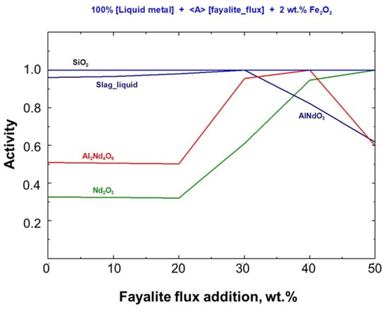
Figure 6.
Fayalite flux effect on activity of stable compound.
Figure 7 shows the thermodynamic analysis of the Stream–4 model, which simulates liquid metal oxidation and slag formation via fayalite flux. This analysis details Gibbs free energy changes and reaction heat variations. Spontaneous redox reactions between the elements present in the liquid metal and the 2FeO·SiO2 compound, resulting in slag formation, were observed at a temperature of 1550 °C. However, when the fayalite flux addition exceeds 30 wt%, the heat released from the oxidation process stabilizes at −25 kJ, and additional heat is required for slag formation, as calculated.
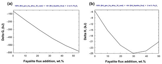
Figure 7.
Thermodynamic analysis of electric steel and magnet smelting on flux addition. (a) Gibbs free energy change and (b) heat of reaction in smelting.
3.2. The Smelting Process of Fe-C Alloy and PM Based on Optimized Modeling
An equilibrium smelting process was conducted that involved the addition of 30 wt.% cast iron to the electric motor and NdFeB magnets, followed by a further addition of 2 wt.% Fe2O3 which acted as an oxidizing agent in the smelting process. An alumina crucible containing a metal sample was used in a 1550 °C equilibrium melting experiment within a super kanthal vertical tube furnace. The heating and cooling processes were carried out at a rate of 5 °C per minute, and a holding period of 3 h was maintained throughout the experiment. Argon gas flowed at 300 mL/min to keep the furnace atmosphere inert. As equilibrium smelting progressed, both the steel and the magnetic materials underwent complete melting, resulting in the creation of a homogeneous bulk metal; concurrently, solid, non-melting powder particles aggregated and accumulated on the surface of this formed bulk metal. The analysis of a solid metal sample, which involved cutting it in half, followed by polishing and subsequent examination using SEM-EDS, revealed a homogeneous macrostructure for the bulk metal; these findings are fully shown in Figure 8. Upon examination, the upper portion of the sectioned sample revealed a significantly elevated concentration of inclusions, in contrast to the predominantly bulk metallic matrix observed in the middle and lower regions. The SEM and EDS mapping images of the bulk metal are shown in Figure 8a,b, respectively. EDS analysis revealed an iron matrix containing carbon as an impurity. EDS mapping in Figure 8c,d shows neodymium oxide inclusions in the iron matrix’s upper region.
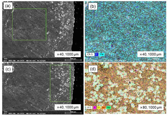
Figure 8.
SEM–EDS analysis of Fe-C alloy in equilibrium smelting. (a) Metal bulk, (b) EDS mapping image of metal bulk, (c) inclusions in metal, and (d) EDS mapping image of inclusions.
Inclusions in the metal matrix were analyzed via EDS mapping; the results are shown in Table 10. The metal matrix contains 73.56% Fe, with inclusions comprising 7.19% Nd and 7.21% O2. In the equilibrium melting experiment, the simulated metal and magnetic materials melted and formed to create a homogeneous bulk metal. However, strongly oxidized REEs and other impurities were included within the metal matrix. The results suggest a significant increase in efficiency could be achieved by utilizing an induction furnace for the melting process, given its capacity for high-intensity melting, its control over liquid metal movement through magnetic fields, and its enhancement of the mixing process.
Table 10.
Elemental distribution within an inclusions at equilibrium smelting.
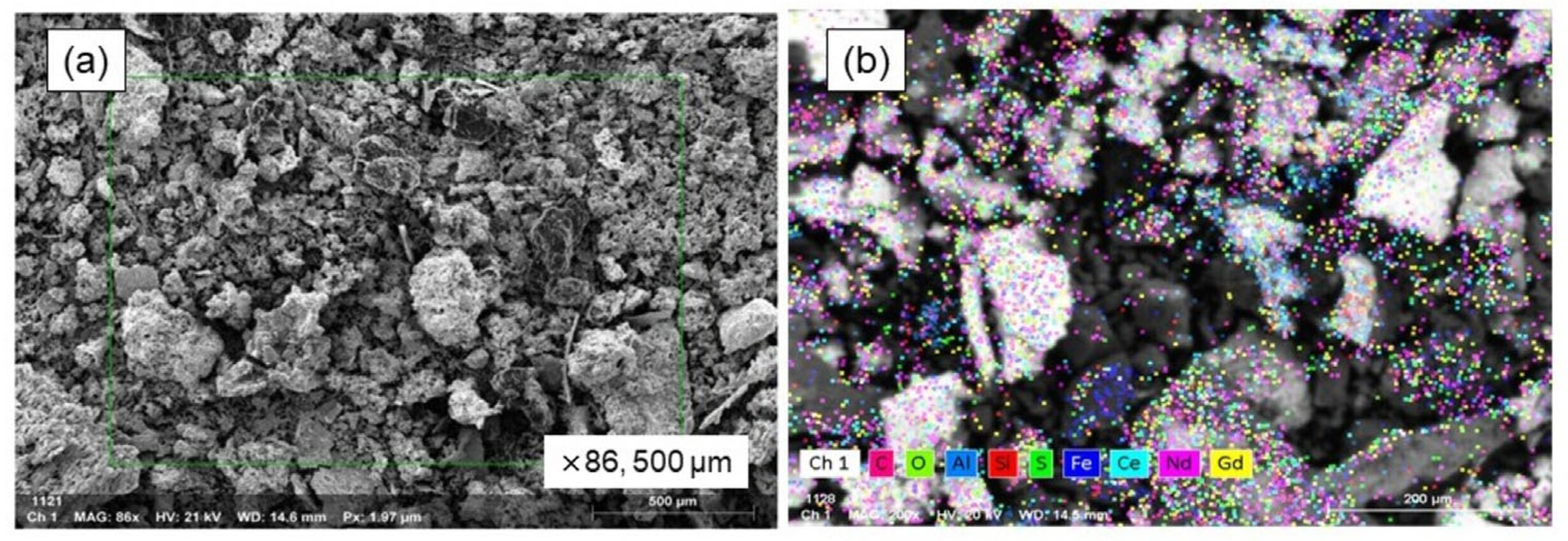
Figure 9 displays the findings from the SEM-EDS analysis conducted on the oxide powder particles that were generated on the surface of the bulk metal. The powders formed (shown in Figure 9a) had a soil-like appearance, marked by an irregular and rough texture, and a broad range of particle sizes. As shown in Figure 9b, the SEM mapping analysis results illustrate the distribution of elements like aluminum, neodymium, iron, silicon, and oxygen, strongly indicating that these elements are present in their oxide forms within the powders.

Figure 9.
SEM–EDS analysis of oxidized powders on metal surface. (a) SEM image of powder and (b) EDS mapping image.
The results of the EDS mapping analysis, showing the distribution of the various elements identified, are shown in Table 11, offering a complete picture of the sample’s elemental makeup. The magnetic material melted, and its REEs were strongly oxidized, forming a non-melting oxide phase, as evidenced by the high neodymium content (35.36 wt.%). The presence of Ce and Gd in EDS analysis might stem from the instrument’s reference database. With only 4.86 wt.% Fe, the powder suggests the Fe2O3 oxidizing agent functioned well.
Table 11.
The elemental distribution of oxidized particles formed during equilibrium smelting.
After the preliminary equilibrium melting experiment had been completed, the subsequent experimental work was carried out using an induction furnace, the specific setup of which is detailed and illustrated in Figure 3. Using an induction furnace, the experiment’s primary goal was to investigate and define the correlation that exists between the quantity of fayalite flux employed and the ultimate neodymium recovery degree achieved. Table 12 shows the chemical composition data for the Fe–C alloys produced during the experiments, which involved the addition of fayalite fluxes at 10 wt.%, 20 wt.%, and 30 wt.% (held for 30 min) and 30 wt.% flux additions held for a longer duration of 60 min. Utilizing OES analysis, the chemical composition of the Fe–C alloy metal was ascertained, concurrently, the neodymium concentration within this metal was quantified via ICP-OES analysis. As the weight percentage of flux increased, from 10 wt.% to 20 wt.% then to 30 wt.%, the carbon content in the metal decreased, going from 2.76% to 2.04% and then to 1.08%, and with a 60 min holding time at 30 wt.% flux, the carbon content further decreased to 1.047%. In a similar vein, the silicon content exhibited a decrease, falling from an initial level of 1.44% down to a final level of 0.13%. The content of neodymium was exceptionally low, with values ranging from a minimum of 0.006% to a maximum of 0.018%. The results confirm the fayalite flux acted as an effective oxidizing agent.
Table 12.
Composition of metal in electric steel and magnet smelting with flux additions analyzed by OES.
Table 13 presents XRF analysis of slag composition changes based on fayalite flux variations. The rise in fayalite flux led to an increase in the SiO2 content in the slag, from around 45% to 52%, while there was also a slight uptick in the iron oxide content. By identifying the Nd2O3 oxide, the presence of neodymium in the slag was verified. ICP-OES analysis provided highly precise measurements of neodymium content, which were found to be 4.91, 5.83, and 4.45 wt.% corresponding to the flux additions. During the experiment lasting 60 min with 30 wt.% flux, it was observed that the SiO2 content decreased to 46.17%, and concurrently, the Fe2O3 content rose to 26.67%, indicating the oxidation of iron from the metal phase due to atmospheric oxygen, thereby elevating its weight percentage in the slag. An interaction occurred between the slag and the alumina crucible, as evidenced by the presence of Al2O3 in the slag; this Al2O3 dissolved into the slag from the crucible.
Table 13.
Composition of slag in electric steel and magnet smelting with fayalite flux analyzed by XRF.
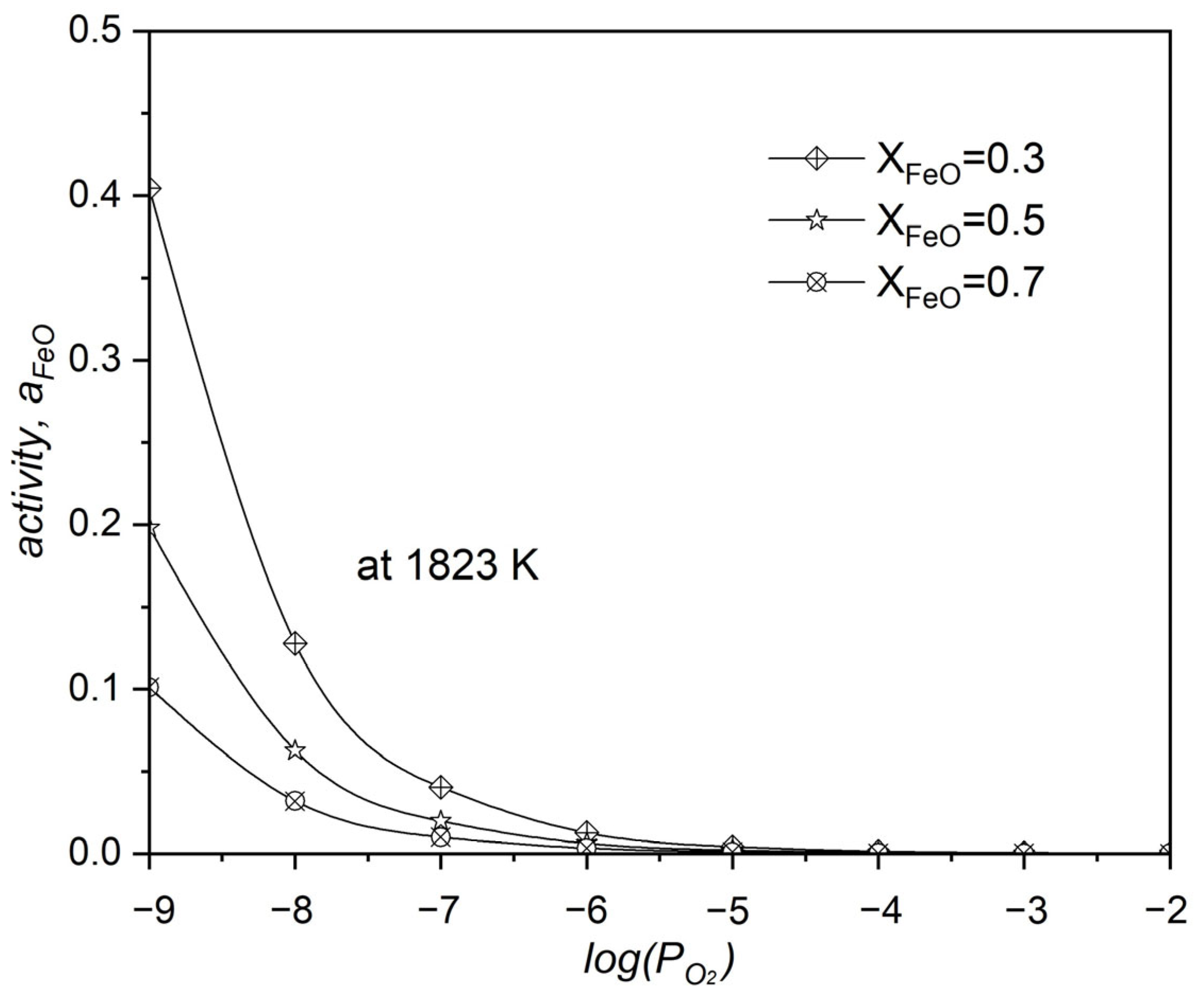
The oxidation process of REEs and various other elements on the liquid iron surface is made easier by the presence of iron III oxide, which functions as an oxidizing agent, and FeO in fayalite. It is believed that there is a transition from iron’s III oxide to FeO on the surface of liquid iron. Equations (10) and (11) are where these processes are clearly outlined. The Gibbs free energy change of −816.7 kJ clearly indicates the strong oxidation tendency of neodymium when it is in liquid metal. With a partial pressure of oxygen () at 1.8 × 10⁻⁹ during the neodymium oxidation by FeO, it is observed to be lower than the equilibrium for FeO, signifying that the reaction advances completely, as described in Equations (12)–(14).
| [Fe](l) + Fe2O3(l) = 3FeO(l) | at 1550 °C ΔG°[FeO] = −86.9 kJ | (10) |
| 2[Nd](l) + 3(FeO)(l) = 3[Fe](l) + (Nd2O3)(s) | ΔG°[Nd2O3] = −816.7 kJ K ≈ 1022 | (11) |
| 2FeO(s) → 2Fe(l) + O2(g) at equal = | ΔG°[FeO] = 284.6 kJ | (12) |
| 2Nd2O3(s) → 4Nd(l) + 3O2(g) | ΔG°[FeO] = 2512.8 kJ | (13) |
| (14) |
The relationship between the activity of FeO, the molar fraction of FeO, and the oxygen partial pressure during the oxidation of neodymium by FeO within the system is shown in Figure 10. The increase in the system’s leads to a decrease in the activity of FeO, a clear indication that the reaction is significantly driven towards producing Nd2O3. One of the factors that is known to increase the value of the is a higher molar fraction of FeO within the system’s composition.
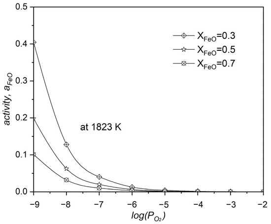
Figure 10.
The influence of oxygen partial pressure () on FeO activity during neodymium’s oxidation with FeO at 1550 °C.
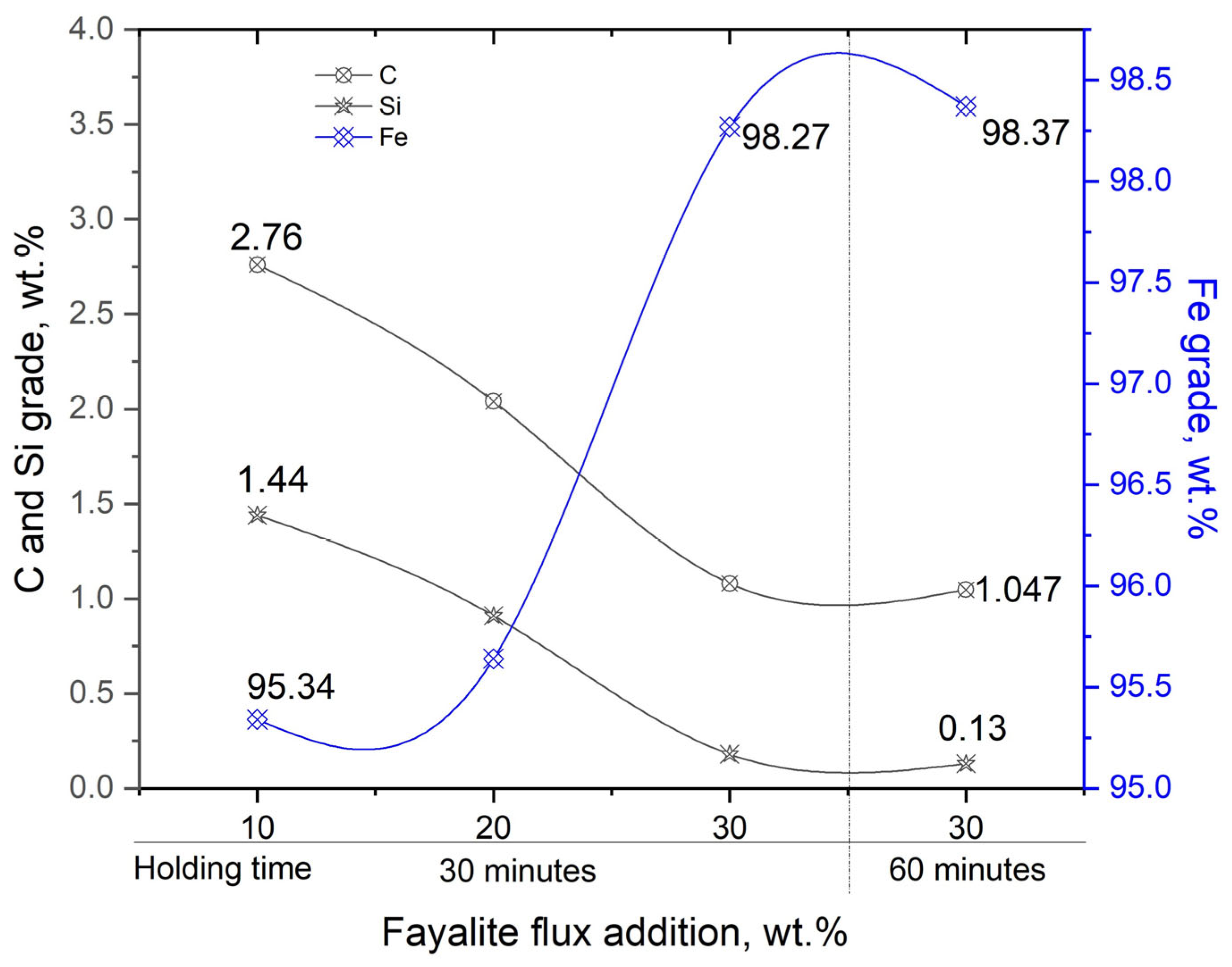
The effect that the quantity of fayalite flux has on the concentration of the impurity elements carbon and silicon, as well as the iron content in liquid iron, is shown in Figure 11. As oxygen (FeO) is added to the liquid iron system, the concentrations of silicon and carbon, which are more readily oxidized than iron, are reduced. Adding a flux with 30 wt.% results in a liquid iron composition that includes approximately 1% carbon and 0.13% silicon. In contrast, a decrease in the content of impurity elements leads to a corresponding increase in the iron grade, exceeding 98%.
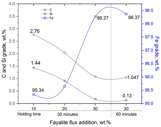
Figure 11.
The influence of flux addition on the elemental composition of metal. A dash line shows holding time defferences.
3.3. Influence of CaO Flux on the Slag Composition
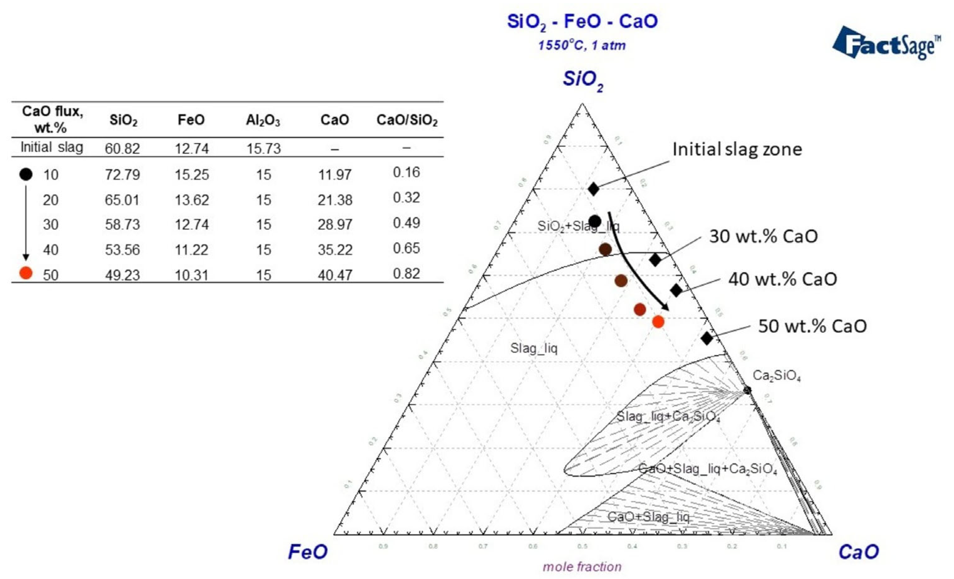
In a smelting test where 30 wt.% fayalite flux was added and held for 30 min, the resulting slag primarily consisted of SiO2, which solidified into a glassy structure. Because fayalite decomposes at 1550 °C, releasing SiO2 from FeO, a silicon tetrahedron matrix of forms in the liquid slag phase. The presence of Me+ cations causes the bond of to break, resulting in the creation of a silicate structure. Orthosilicates, with a chemical formula denoted as nRexOy·SiO2, are formed through a reaction that involves the combination of REEs oxides and available [45]. Silicate formation in the Nd2O3–SiO2 binary system results in the creation of several distinct silicates, specifically Nd2SiO5, Nd2Si2O7, and Nd14Si9O39, showcasing the various stoichiometries achievable in this system. In the binary system of SiO2-rich slags, studies conducted by Leszek et al. [46], Yuji et al. [47], and Thu et al. [48] have observed the formation of a mixture consisting of Nd2Si2O7 + SiO2(s). The Nd2O3–SiO2 binary system shows that a combination with 0.72% mol SiO2 has the unique property of melting at the lowest temperature, specifically at 1600 °C [49]. The slag produced during the experiment contains around 4 wt.% of Nd2O3, a concentration considered insufficient to transform the based structure of the slag. This glassy slag, characterized by its high melting temperature and high viscosity, presents a challenge in terms of mobility on the liquid metal, potentially hindering the dissolution of REEs and complicating the overall process. Due to their ability to readily break the bond of , Ca2+ have been the subject of extensive study and widespread application within the CaO–SiO2 system. The integration of Ca2+ cations into the Nd2O3–SiO2 system facilitates the formation of various solid phases, including, but not limited to, Ca2−2xNd2xSiO4Ox, Ca3−3xNd2xSiO5, and Ca2+10xNd8−8x(SiO4)6O2−2x, as evidenced by studies [36,48]. A research study conducted by Le et al. [50] reported that at a temperature of 1600 °C, neodymium precipitation was observed to form within the Liquid(CaSiO3)+ Ca2+xNd8−x(SiO4)6O2−0.5x state. Figure 12 shows the CaO–SiO2–FeO system upon which a slag composition model was constructed; the results of smelting processes that used flux additives are shown and discussed in detail. In the modeled system, the absence of CaO in the initial slag composition is noteworthy, and the system’s structural changes as CaO was added are represented by the colored circular symbols. With additions of 10 wt.% and 20 wt.% CaO, the slag is found to be in a region characterized by a mixture of liquid slag and solid SiO2. However, when 30 wt.% or more CaO is added, the slag transitions into a liquid state. As shown in the modeled slag composition in Figure 12, the CaO/SiO2 ratios are calculated as 0.49, 0.65, and 0.82 for 30 wt.%, 40 wt.%, and 50 wt.% CaO additions, respectively. Given its basicity, this slag is predicted to show typically acidic properties.

Figure 12.
Analyzing slag structure on CaO–SiO2–FeO ternary system using FToxid data, Factsage 8.2 at 1550 °C, 1 atm.
Table 14 shows XRF analysis on the slag composition produced during smelting incorporating 30 wt.% fayalite flux and CaO flux additions. With the rise in CaO flux addition, SiO2 content dropped from 39.78% to 34.83% and 24.65%, as CaO content increased from 20.23% to 24.81% and 28.89%. The slag exhibited a basicity of 0.50 when the CaO addition reached 30 wt.%, increasing to 0.71 at 40 wt.% CaO, and further rising to 1.17 at the 50 wt.% CaO. In the slag, the dominant compound 2FeO·SiO2 is decomposed by CaO, which simultaneously enhances the reduction in FeO. A corresponding decrease in Nd2O3 content, from an initial 4.01% down to 3.20% and further to 2.83%, was observed with an increase in slag volume. ICP-OES analysis revealed a similar decreasing in Nd2O3 content, from 3.45 wt.% to 2.72 wt.% and further to 1.80 wt.%. One significant issue encountered during our experiments stemmed from the interaction observed between the slag and the alumina crucible, a complication that manifested as a demonstrable increase in the Al2O3 content within the slag, thereby adding complexity to our experimental procedures.
Table 14.
Composition of slag in electric steel and magnet smelting with flux and CaO additions by XRF.
3.4. The Correlation Between the Flux Addition and the Neodymium Recovery Within the Slag
Neodymium recovery efficiency in the induction furnace, influenced by flux additives, is determined by the quantity of neodymium detected in the slag. Table 15 provides information on the neodymium amount in the raw material, the weight of the slag, and the neodymium content in the slag. When 10 wt.% fayalite flux was added, the resulting slag weighed 55.51 g; however, increasing the fayalite flux to 20 and 30 wt.% resulted in slag weights of 65.82 and 85.26 g, respectively. With the addition of CaO flux, the slag weight, which initially comprised 30 wt.% fayalite, exhibited a clear upward trend directly related to the concentration of CaO oxide, a relationship detailed in the accompanying table. The neodymium content in the slag underwent assessment via ICP–OES analysis, yielding results that detailed the precise amounts of neodymium found within the slag.
Table 15.
Determining the efficiency of neodymium recovery.
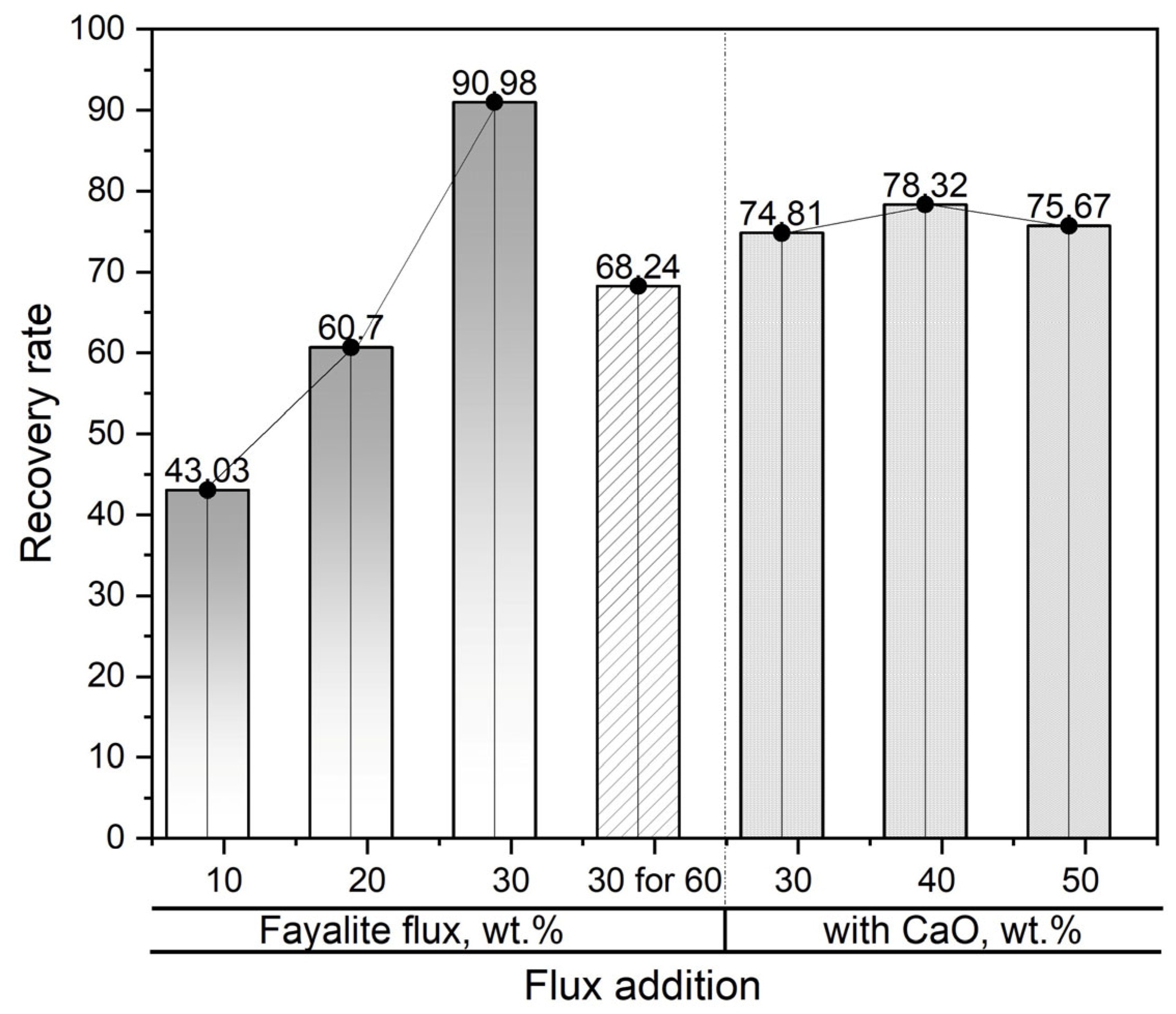
In Figure 13, the effectiveness of using slag to recover neodymium is shown during smelting operations with the addition of fayalite flux and CaO flux as enhancement materials. The lowest neodymium recovery degree observed in the experiment was 43.03%, which was obtained after the metal material was melted at 1550 °C and held at that temperature for a period of 30 min with the addition of 10 wt.% fayalite flux. However, a sharp increase in the neodymium recovery degree, to 60.7% and 90.98%, respectively, was observed when the fayalite addition increased to 20 wt.% and 30 wt.%. The experiment involved holding the liquid metal, with its 30 wt.% fayalite addition, for 60 min; subsequently, a reduction in the neodymium recovery rate was noted, this decrease pointing to considerable interaction occurring between the neodymium oxide and the alumina crucible used in the process. The neodymium recovery efficiencies observed in smelting trials employing 30 wt.% fayalite and different levels of CaO flux additives showed no significant differences after a 30 min hold, thereby suggesting that increasing the CaO concentration had a negligible impact on the recovery process. However, the decreased neodymium recovery was attributed to Ca2+ cations enhancing the interaction of Nd3+ cations with the alumina crucible. In this experiment, slag processing reached a maximum neodymium recovery efficiency of 90.98%.
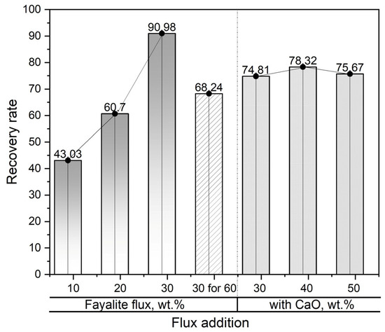
Figure 13.
Correlation between flux addition and neodymium recovery yield. CaO additions are shown by a dash line.
4. Conclusions
In this research, electric steel and the magnetic materials of PM motors were smelted together, following which rare earth elements (REEs) were oxidized from the liquid metal by employing iron oxide (Fe2O3) and fayalite (2FeO·SiO4) as oxidizers; the experimental work, which successfully separated the REEs into slag, was predicated on thermodynamic modeling optimized through the use of the FactSage program. The following are our research findings:
- REEs in liquid metal exhibit strong oxidation tendencies, with Gibbs free energy values for oxidation by fayalite of ΔG°[Nd] = −427 kJ, ΔG°[Dy] = −452 kJ, and ΔG°[Nb] = −186 kJ, respectively.
- At equilibrium smelting, electric steel and magnetic materials fully melted to form a bulk metal, but neodymium oxide inclusions heavily accumulated in the upper region, with REE oxide particles forming on the metal surface.
- For neodymium oxidation in liquid iron by FeO, the needed (1.8 × 10⁻⁹) is less than the FeO equilibrium partial pressure. Increased system correlated with increased and decreased .
- Nd3+ ions break down the base within the liquid slag, resulting in Nd2Si2O7 silicate formation, which is then broken down by Ca2+ cations.
- The 30 wt.% fayalite flux addition resulted in a maximum neodymium recovery efficiency of approximately 91% in the slag.
This study proved that mass smelting waste PM motors and separating REEs into slag is feasible. Although alumina crucibles offer the benefit of minimal thermal degradation during high-temperature processes, a significant drawback is their tendency to actively interact with and be chemically altered by the slag, potentially compromising experimental results. Although there were challenges, the experiment’s data closely simulated practical industrial scenarios, offering a considerable advantage in their applicability to real-industrial settings.
Author Contributions
E.U., methodology, data curation, investigation, writing—original draft, Software, writing—review and editing, data curation; J.-H.P., formal analysis, software; Y.-J.C., project administration, funding acquisition; J.-P.W., project administration, conceptualization. All authors have read and agreed to the published version of the manuscript.
Funding
This research was funded by the Hyundai Motor Group.
Data Availability Statement
The original contributions presented in the study are included in the article, further inquiries can be directed to the corresponding author.
Conflicts of Interest
Authors Erdenebold Urtnasan, Jeong-Hoon Park, Jei-Pil Wang have received research grants from Hyundai Motor Group but declare that they have no other conflicts of interest related to this research. Author Yeon-Jun Chung is employed by Hyundai. The remaining authors declare that the research was conducted in the absence of any commercial or financial relationships that could be construed as a potential conflict of interest.
References
- Racunaliske novice. Electric Cars with the Longest Range. Available online: https://www.racunalniske-novice.com/en/electric-cars-with-the-longest-range/ (accessed on 3 October 2024).
- ACKO. 15 Long-Range Electric Cars in India in 2025. Available online: https://www.acko.com/car-guide/long-range-electric-cars-in-india/ (accessed on 31 December 2024).
- Divyani, J.; Sunil, K.; Shally, V. Introduction to artificial intelligence-empowered electric vehicles in smart grids. In Artificial Intelligence-Empowered Modern Electric Vehicles in Smart Grid Systems; Aparna, K., Sudeep, T., Eds.; Elsevier: Amsterdam, The Netherlands, 2024; pp. 3–31. [Google Scholar] [CrossRef]
- Arévalo, P.; Ochoa-Correa, D.; Villa-Ávila, E. A Systematic Review on the Integration of Artificial Intelligence into Energy Management Systems for Electric Vehicles: Recent Advances and Future Perspectives. World Electr. Veh. J. 2024, 15, 364. [Google Scholar] [CrossRef]
- Evs&Beyond. 2024 Breaks Global EV Sales Record with Over 17 Million Units Sold. Available online: https://evsandbeyond.co.nz/2024-breaks-global-ev-sales-record-with-over-17-million-units-sold/#:~:text=Electric%20vehicle%20(EV)%20sales%20reached,1.3%20million%20(+27%25) (accessed on 16 January 2025).
- RHO Motion. Over 17 Million EVs Sold in 2024—Record Year. Available online: https://rhomotion.com/news/over-17-million-evs-sold-in-2024-record-year/#:~:text=Over%2017%20million%20EVs%20sold%20in%202024,*%20Rest%20of%20World:%201.3%20million%2C%20+27% (accessed on 14 January 2025).
- Mohamed, K.; Nassar, Y.; El-Khozondar, H.J.; Monaem, E.R.Z.; Yaghoubi, E.; Yaghoubi, E. Electric Vehicles in China, Europe, and the United States: Current Trend and Market Comparison. Int. J. Electr. Eng. Sustain. 2024, 2, 1–20. Available online: https://ijees.org/index.php/ijees/article/view/70 (accessed on 9 January 2024).
- IEA.org. The Global Electric Vehicle Fleet is Set to Grow Twelve-Fold by 2035 Under Stated Policies. Available online: https://www.iea.org/reports/global-ev-outlook-2024/outlook-for-electric-mobility (accessed on 23 April 2024).
- Hou, L.; Guo, Y.; Ba, X.; Lei, G.; Zhu, J. Efficiency Improvement of Permanent Magnet Synchronous Motors Using Model Predictive Control Considering Core Loss. Energies 2024, 17, 773. [Google Scholar] [CrossRef]
- Özçiflikçi, O.E.; Koç, M.; Bahçeci, S.; Selcuk, E. Overview of PMSM control strategies in electric vehicles: A review. Int. J. Dynam. Control 2024, 12, 2093–2107. [Google Scholar] [CrossRef]
- Sergakis, A.; Salinas, M.; Gkiolekas, N.; Gyftakis, K.N. A Review of Condition Monitoring of Permanent Magnet Synchronous Machines: Techniques, Challenges and Future Directions. Energies 2025, 18, 1177. [Google Scholar] [CrossRef]
- Orlova, S.; Rassõlkin, A. Permanent Magnets in Sustainable Energy: Comparative Life Cycle Analysis. Energies 2024, 17, 6384. [Google Scholar] [CrossRef]
- Usman, A.; Saxena, A. Technical Roadmaps of Electric Motor Technology for Next Generation Electric Vehicles. Machines 2025, 13, 156. [Google Scholar] [CrossRef]
- Ranjan, P.; Kalla, U.K. Comprehensive Study on Various Types of Magnets Used in Permanent Magnet Electrical Motors. In Proceedings of the 2024 IEEE Region 10 Symposium (TENSYMP), New Delhi, India, 27–29 September 2024; pp. 1–7. [Google Scholar] [CrossRef]
- Karami, R.; Butler, D.; Tamimi, S. Manufacturing of non-grain-oriented electrical steels: Review. Int. J. Adv. Manuf. Technol. 2024, 133, 1083–1109. [Google Scholar] [CrossRef]
- Lukas, N.; Herbert, K.; Herbert, L.; Thomas, H.; Christof, S. Microstructural and textural evolution of double stage cold rolled non-grain oriented electrical steel. J. Magn. Magn. Mater. 2024, 597, 172032. [Google Scholar] [CrossRef]
- He, Y.; Kestens, L.A. The processing, microstructure, texture, and magnetic properties of electrical steels: A review. Int. Mater. Rev. 2025, 1, 1. [Google Scholar] [CrossRef]
- Ning, S.; Seangwong, P.; Fernando, N.; Siritaratiwat, A.; Khunkitti, P. A novel double stator hybrid-excited Halbach permanent magnet flux-switching machine for EV/HEV traction applications. Sci. Rep. 2024, 14, 18636. [Google Scholar] [CrossRef] [PubMed]
- Ma, J. Magnetic Field Analysis and Development of Disk Axial–Radial Hybrid Excitation Generator for Range Extenders in Extended-Range Electric Vehicles. World Electr. Veh. J. 2024, 15, 94. [Google Scholar] [CrossRef]
- Hosseinpour, A.; Rahideh, A.; Abbas, A.; Iqbal, A.; El-Bayeh, C.Z.; Flah, A.; Ali, E.; Ramy, N.R.G. Calculating torque, back-EMF, inductance, and unbalanced magnetic force for a hybrid electrical vehicle by in-wheel drive application. Sci. Rep. 2024, 14, 12912. [Google Scholar] [CrossRef] [PubMed]
- Velikov, A.; Nachev, A.; Gueorguiev, N.; Bachvarov, R.; Stanev, S.; Nenova, L.; Maneva, A.; Nikolov, K.; Pavlova, D. Optimization the Phase Composition of Aluminum Alloys for Motor Parts Operating at Incresed Temperatures. In Proceedings of the 2024 6th International Conference on Control Systems, Mathematical Modeling, Automation and Energy Efficiency (SUMMA), Lipetsk, Russian, 13–15 November 2024; pp. 603–607. [Google Scholar] [CrossRef]
- Yavaş, A.; Cilingir, C.; Turk, A.; Celik, A. Production and Characterization of Highly Conductive Aluminum Metal for Electric Motor Applications. J. Mater. Eng. Perform. 2025, 34, 1705–1716. [Google Scholar] [CrossRef]
- Li, Z.; Ahmed, S.H.; Zhiming, Y.; Anwar, S.; Sumit, H.; Juliette, S.; Caroline, G.; Syed, H.A.; Friya, T. A circular economy approach for recycling Electric Motors in the end-of-life Vehicles: A literature review. Resour. Conserv. Recycl. 2024, 205, 107582. [Google Scholar] [CrossRef]
- Tiwari, D.; Miscandlon, J.; Tiwari, A.; Jewell, G.W. A Review of Circular Economy Research for Electric Motors and the Role of Industry 4.0 Technologies. Sustainability 2021, 13, 9668. [Google Scholar] [CrossRef]
- Chang, M.M.L.; Ong, S.K.; Nee, A.Y.C. Approaches and Challenges in Product Disassembly Planning for Sustainability. Procedia CIRP 2017, 60, 506–511. [Google Scholar] [CrossRef]
- Mitrouchev, P.; Wang, C.G.; Lu, L.X.; Li, G.O. Selective disassembly sequence generation based on lowest level disassembly graph method. Int. J. Adv. Manuf. Technol. 2015, 80, 141–159. [Google Scholar] [CrossRef]
- Cao, R.; Mi, C.; Cheng, M. Quantitative Comparison of Flux-Switching Permanent-Magnet Motors With Interior Permanent Magnet Motor for EV, HEV, and PHEV Applications. IEEE Trans. Magn. 2012, 48, 2374–2384. [Google Scholar] [CrossRef]
- James, D.W.; Richard, M.; Mohammed, K. Electric vehicle traction motors without rare earth magnets. Sustain. Mater. Technol. 2015, 3, 7–13. [Google Scholar] [CrossRef]
- Katsunori, Y.; Rare Earth Element Recovery Technology for Motor Magnets for Electric Vehicles that Aims to Reduce Costs in a Short Time. Science Technology Innovation Japan. Available online: https://sj.jst.go.jp/stories/2022/s0301-01a.html (accessed on 1 March 2022).
- Saito, T.; Sato, H.; Ozawa, S.; Yu, J.; Motegi, T. The extraction of Nd from waste Nd–Fe–B alloys by the glass slag method. J. Alloys Compd. 2003, 353, 189–193. [Google Scholar] [CrossRef]
- Yang, Y.; Abrahami, S.T.; Xiao, Y. Recovery of rare earth elements from EOL permanent magnets with molten slag extraction. In Proceedings of the 3rd International Slag Valorisation Symposium; ACCO: Leuven, Belgium, 2013; pp. 249–252. [Google Scholar]
- Zhang, Y.; Gu, F.; Su, Z.; Liu, S.; Anderson, C.; Jiang, T. Hydrometallurgical Recovery of Rare Earth Elements from NdFeB Permanent Magnet Scrap: A Review. Metals 2020, 10, 841. [Google Scholar] [CrossRef]
- Xiao, F.; Hu, W.; Zhao, J.; Zhu, H. Technologies of Recycling REEs and Iron from NdFeB Scrap. Metals 2023, 13, 779. [Google Scholar] [CrossRef]
- Oksana, D.; Natalia, K.; Vadim, K.; Gulaim, S. Recovery of rare earth elements from NdFeB magnet by mono- and bifunctional mesoporous silica: Waste recycling strategies and perspectives. Hydrometallurgy 2022, 210, 105855. [Google Scholar] [CrossRef]
- Zhou, Y.; Liu, J.; Cheng, G.; Xue, X.; Yang, H. Kinetics and mechanism of hydrochloric acid leaching of rare earths from Bayan Obo slag and recovery of rare earth oxalate and high purity oxides. Hydrometallurgy 2022, 208, 105782. [Google Scholar] [CrossRef]
- Blenau, L.W.; Vogt, D.; Lonski, O.; Abrar, A.; Fabrichnaya, O.; Charitos, A. Development of a Process to Recycle NdFeB Permanent Magnets Based on the CaO-Al2O3-Nd2O3 Slag System. Processes 2023, 11, 1783. [Google Scholar] [CrossRef]
- Yang, Z.; Xiao, F.; Sun, S.; Zhong, H.; Tu, G. REEs recovery from molten salt electrolytic slag: Challenges and opportunities for environmentally friendly techniques. J. Rare Earths 2024, 42, 1009–1019. [Google Scholar] [CrossRef]
- Elwert, T.; Goldmann, D.; Römer, F.; Buchert, M.; Merz, C.; Schueler, D.; Sutter, J. Current Developments and Challenges in the Recycling of Key Components of (Hybrid) Electric Vehicles. Recycling 2016, 1, 25–60. [Google Scholar] [CrossRef]
- Bast, U.; Recycling von Komponenten und Strategischen Metallen aus Elektrischen Fahrantrieben: MORE (Motor Recycling). Final Research Report. 2014. Available online: http://edok01.tib.uni-hannover.de/edoks/e01fb15/826920594.pdf (accessed on 16 September 2015).
- Li, Y.; Hu, A.; Fu, Y.; Liu, S.; Shen, W.; Hu, H.; Nie, X. Al Alloys and Casting Processes for Induction Motor Applications in Battery-Powered Electric Vehicles: A Review. Metals 2022, 12, 216. [Google Scholar] [CrossRef]
- Fonnov Aluminium. 6063 Aluminum Extrusion For Large Water-cooled Electric Motor Housing. Available online: https://www.fonnovaluminium.com/product/water-cooled-electric-motor-housing-aluminum-extrusions (accessed on 21 December 2023).
- Stornelli, G.; Faba, A.; Di Schino, A.; Folgarait, P.; Ridolfi, M.R.; Cardelli, E.; Montanari, R. Properties of Additively Manufactured Electric Steel Powder Cores with Increased Si Content. Materials 2021, 14, 1489. [Google Scholar] [CrossRef]
- Kim, K.O.; Jung, Y.H.; Park, J.C.; Lim, M.S. Comparative Study of Mechanical and Electrical Characteristics of High-Strength and Conventional Electrical Steel for EV Traction High-Speed Multilayer IPMSM Using Rare-Earth Free PM. IEEE Trans. Magn. 2023, 59, 8102205. [Google Scholar] [CrossRef]
- Lobo, J.A.; Geiger, G.H. Thermodynamics and solubility of carbon in ferrite and ferritic Fe-Mo alloys. Metall. Trans. A 1976, 7, 1347–1357. [Google Scholar] [CrossRef]
- Kiyoshi, K.; Yoshio, S. Rudimental research progress of rare-earth silicate oxyapatites: Their identification as a new compound until discovery of their oxygen ion conductivity. J. Ceram. Soc. Jpn. 2014, 122, 649–663. [Google Scholar] [CrossRef]
- Leszek, K.; Marek, W.; Marek, D. Interfacial reactions and silicate formation in highly dispersed Nd2O3–SiO2 system. Mater. Chem. Phys. 2006, 96, 353–360. [Google Scholar] [CrossRef]
- Yuji, M.; Mikio, H.; Kohei, K. Reinvestigation of phase relations around the oxyapatite phase in the Nd2O3–SiO2 system. J. Cryst. Growth 2003, 247, 207–212. [Google Scholar] [CrossRef]
- Thu, H.L.; Kai, T.; Sander, A.; Annelies, M.; Bart, B.; Muxing, G. Thermodynamic assessment of the Nd2O3-CaO-SiO2 ternary system. Calphad 2016, 55, 157–164. [Google Scholar] [CrossRef]
- Wei, W.; Li, S.; Zhang, B.; Cao, Z.M. Experimental study of the phase relations in Nd2O3-SiO2-FeOx system at 1773 K with p(O2) = 10−7 atm. Ceram. Int. 2025, 51, 18226–18235. [Google Scholar] [CrossRef]
- Le, T.H.; Malfliet, A.; Blanpain, B.; Muxing, G. Phase Relations of the CaO-SiO2-Nd2O3 System and the Implication for Rare Earths Recycling. Metall. Mater. Trans. B 2016, 47, 1736–1744. [Google Scholar] [CrossRef]


Disclaimer/Publisher’s Note: The statements, opinions and data contained in all publications are solely those of the individual author(s) and contributor(s) and not of MDPI and/or the editor(s). MDPI and/or the editor(s) disclaim responsibility for any injury to people or property resulting from any ideas, methods, instructions or products referred to in the content. |
© 2025 by the authors. Licensee MDPI, Basel, Switzerland. This article is an open access article distributed under the terms and conditions of the Creative Commons Attribution (CC BY) license (https://creativecommons.org/licenses/by/4.0/).