1. Introduction
Gears are mechanical components that enable efficient energy transmission by changing the speed and torque of rotational movements [
1]. They are widely used in many sectors, such as automotive, aviation, industrial machinery, aerospace, mining, renewable energy, and consumer electronics [
2,
3,
4]. The quality of gears, one of the basic components of various machinery and equipment, directly affects the performance and lifetime of the machines [
5,
6]. Under the influence of thermo-mechanical loads, gear teeth are subject to significant surface degradation caused by adhesive and abrasive mechanisms. During this wear process, material is transferred between contacting tooth surfaces, which may result in critical malfunctions. In advanced stages, such wear can also lead to tooth fracture in the gear system [
7,
8,
9]. In contemporary manufacturing environments, the pursuit of higher precision and operational efficiency has intensified, making quality control a pivotal aspect of minimizing waste and ensuring resource optimization by allowing only defect-free products to advance along the production line [
10,
11]. As production processes grow increasingly continuous and large-scale, the implementation of systems that reduce material and operational losses has become indispensable. Specifically, the detection of surface defects on gear teeth plays a crucial role in avoiding functional failures and prolonging the operational lifespan of machinery. Conventional visual inspection methods, however, are both labor-intensive and susceptible to human error, which has led to a growing shift toward automated inspection solutions. Thanks to technological advancements, it is now feasible to integrate intelligent systems capable of performing real-time inspection and classification directly within production lines [
12,
13,
14,
15]. Comparable implementations of image processing in automated classification tasks have been successfully applied in the previous literature studies [
16,
17,
18,
19]. Machine vision systems (MVSs), in conjunction with deep learning techniques, have proven to be highly effective in the identification and classification of surface defects on gears. Recent research underscores the capability of deep learning-based methods to deliver both high accuracy and operational efficiency in gear defect inspection tasks [
20,
21,
22]. As a result, the industrial sector increasingly seeks automated solutions for inspection and sorting, leveraging the capabilities of MVSs to meet these demands [
14,
15]. Gan et al. [
15] developed a machine vision-based sorting platform that utilizes air-blowing technology for the classification of high-grade tea leaves, a key product in China’s tea industry. The production of such tea requires the use of fresh leaves that are uniform in tenderness and size. Despite this need, existing sorting equipment lacks the precision and efficiency necessary for handling fresh tea leaves (FTLs). To address this gap, the researchers proposed a vision-guided system tailored for sorting FTLs. Their findings indicate that, while the system is capable of supporting small-scale production demands, its overall accuracy still falls short of optimal standards [
15]. Zhou et al. [
23] developed a high-speed cork sorting system utilizing machine vision technology. Their approach employed an advanced deep learning framework to inspect cork surfaces and perform automated classification. Experimental findings demonstrated that the system achieved high sorting accuracy with reduced processing time, though further improvements in speed were recommended [
23]. Similarly, Lu et al. [
24] introduced a machine vision-guided robotic system for sorting winter jujubes cultivated in China based on their ripeness levels. The system integrated image processing directly into the robotic arm, which carried out the sorting operations. This study reported high classification accuracy; however, the authors emphasized the need for future enhancements to the robotic mechanism and overall sorting efficiency. In parallel, gear manufacturing is increasingly adopting sophisticated image processing techniques to enhance the precision and efficiency of defect detection. The application of deep learning-based models for identifying surface flaws on gear teeth represents a promising advancement in quality control methodologies [
24]. Previous research has identified several limitations concerning the accuracy, speed, and overall efficiency of existing sorting systems. In response to these challenges, Rezaei et al. [
25] designed, developed, and evaluated an automated sorting machine aimed at detecting and separating sunburned pomegranates—a condition that affects nearly 30% of the harvested yield and poses a significant obstacle in the commercial distribution of the fruit. This study introduced three novel image processing algorithms for sunburn detection. Although the proposed methods successfully enabled the sorting of affected pomegranates, the classification accuracy varied across the different algorithms [
25]. The application of such advanced image-based approaches to the inspection of gear surface defects holds considerable potential for enhancing the accuracy and reliability of automated quality control processes in manufacturing environments.
Research Gaps Identified:
Lack of high-precision, high-speed, and cost-effective defective object detection in real-time.
Limited systems optimized for rotational, symmetrical components such as gears.
Insufficient integration of image-based evaluation with mechanical actuation mechanism in one compact system.
Objectives of this Study:
Development of a machine vision system for high-speed gear defect detection.
Achievement of detection precision above 95% in real-time monitoring conditions.
Implementation of a compact, low-cost, and scalable system with the integration of machine vision and pneumatic actuator sorting.
This study introduces a gear inspection and separation system developed using a machine vision system (MVS), specifically designed to address previously identified limitations in accuracy, speed, and operational efficiency. The proposed system monitors gears transported on a rotating table and classifies them based on surface defects, utilizing MVS for real-time analysis. Defective gears—exhibiting issues such as broken or missing teeth, surface irregularities, or dimensional inaccuracies—are identified and subsequently removed from the production line via a pneumatic valve mechanism. The MVS is strategically positioned to continuously observe and evaluate the condition of each gear as it moves along the table.
In essence, this study presents a fully automated sorting solution that integrates advanced image processing with mechanical actuation to ensure that only defect-free components proceed along the manufacturing line. By reducing waste and improving process reliability, this approach offers a practical and scalable advancement for quality assurance in automated production systems.
2. Materials and Methods
The machine vision system (MVS) is integrated with a computer interface and programmed to differentiate between defect-free and faulty gears based on predefined criteria. The system is configured to identify key attributes of acceptable gears, such as a complete set of teeth, uniform surface texture, and accurate dimensional specifications. Upon detecting a deviation from these standards, the MVS communicates with a microcontroller, which then activates a pneumatic solenoid valve. This valve, powered by compressed air from a connected compressor, removes the defective gear from the rotating inspection table, while compliant gears continue along the production line. This automated quality control mechanism not only improves operational efficiency but also minimizes the risk of faulty components reaching later stages of manufacturing or assembly.
The schematic representation of the system is provided in
Figure 1. In essence, image data are processed by the industrial PC (IPC), and based on the analysis, a command signal is relayed to the microcontroller. The microcontroller then triggers a relay, which actuates the pneumatic valve to eject defective gears from the rotating platform.
The IPC (industrial PC) handles image acquisition, conversion to HSV color space, noise reduction, and binary segmentation via thresholding. Following feature extraction (area, contour), the IPC communicates with the MCU (microcontroller unit), which interprets gear quality based on preloaded logic. The MCU then actuates the pneumatic solenoid valve through a relay driver, executing the decision-making process in under 60 milliseconds.
A three-stage system is developed for the classification of gears as defective or non-defective and their separation using image processing techniques. In the first stage of the system, an image preprocessing step is applied to the image taken from the camera. In the second stage, the gears in the environment are detected, and data related to the gears are transferred to the information database as either defective or non-defective. In the final stage, using the dataset, defective gears are separated while non-defective gears continue to progress. In this study, gears moving on the rotating table are detected for common defects such as missing teeth, rough surfaces, incorrect diameters, and other flaws, and these defective gears are separated.
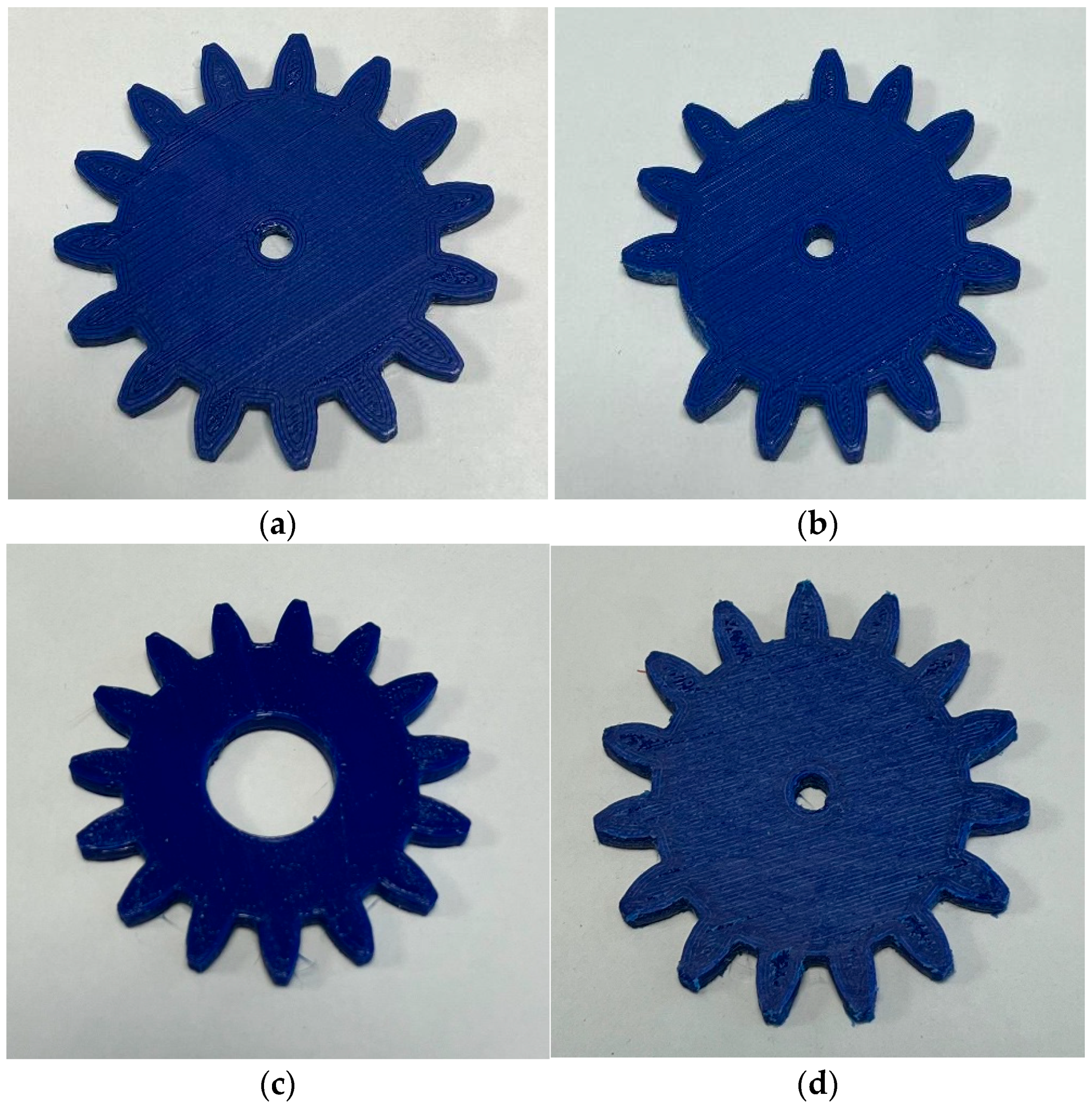
The gears shown in
Figure 2 were used during the initial phase of operation until the system was fully calibrated. They were printed using an Adventurer 5M Pro 3D printer with Creality PLA Plus filament. The slicing was performed using an Orca Slicer. Printing parameters included a 210 °C hot end temperature, 65 °C heated bed temperature, and 50% infill.
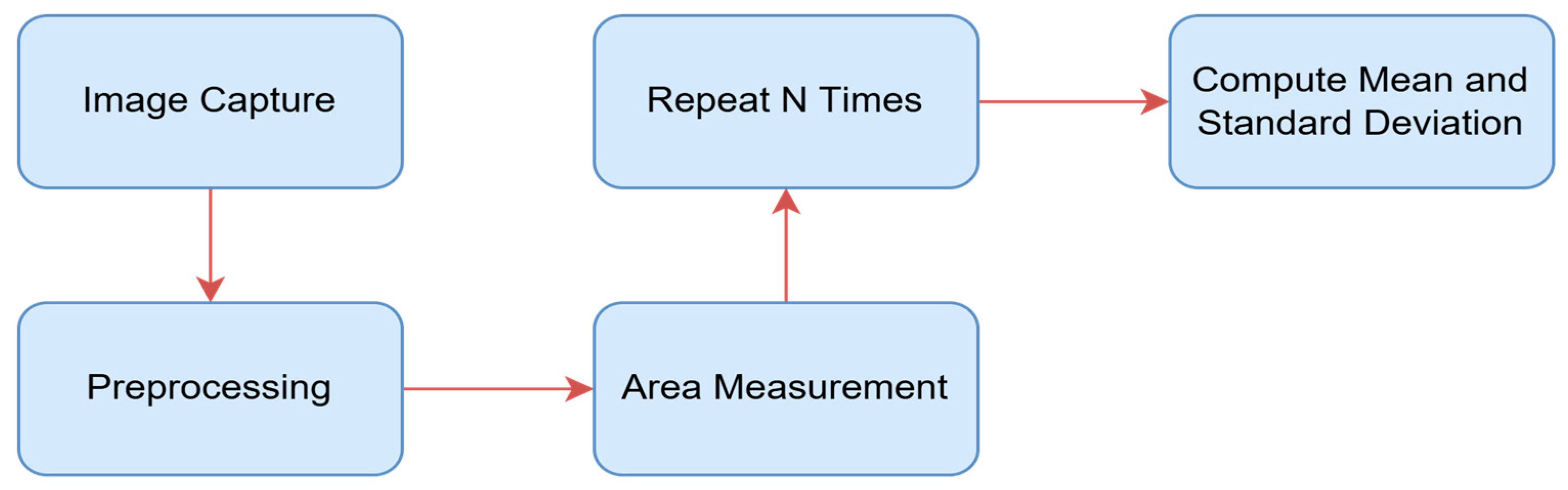
The image processing process begins with the acquisition of the image. The image, converted into a digital signal, is enhanced through preprocessing. Then, with the segmentation phase, gaps and background noises are eliminated. The boundaries of gears are determined by the contouring process. With data extraction, dimensions, shape, color, texture, and defects are measured. Subsequently, the gears are classified based on their characteristics. Finally, the gears are characterized with respect to the quality control parameters. The image processing pipeline included the following steps: image acquisition via an industrial RGB camera; preprocessing with Gaussian blur for noise reduction; conversion to HSV color space for effective background masking; segmentation using Otsu’s thresholding; and contour extraction via Canny edge detection. No machine learning-based classifier was used in this study; instead, binary classification was performed based on geometric area deviations. This rule-based method enabled fast decision-making but is planned to be enhanced with convolutional neural networks (CNNs) in future iterations for improved defect characterization.
The preprocessing pipeline consists of the following steps:
- (1)
RGB image is converted to grayscale using:
- (2)
Gaussian blur is applied using the following:
- (3)
Histogram equalization enhances contrast, and
- (4)
Otsu’s thresholding calculates optimal global threshold T by minimizing intra-class variance:
Finally, morphological operations (erosion and dilation) are applied to remove noise and close contour gaps.
The first step in image processing is acquiring a digital image with a digital camera. The next stage after obtaining the digital image is preprocessing. Preprocessing involves subjecting the obtained digital image to certain preliminary processes to achieve a more successful result before using it. These processes can be categorized under the subheadings of image enhancement, image restoration, and image compression (
Figure 3).
In image processing steps, one of the color spaces applicable to pixels and the most commonly used is RGB (red, green, blue), obtained by the combination of the three primary colors. The other system is monochrome (black and white). Here in this study, RGB images are converted to the HSV to separate the target objects from the background.
Operations in image processing are performed on pixels, which are the smallest units that constitute the image. First, the digitized image is converted to grayscale to clean up noise. Then, additional filters are applied, including capturing the image, cleaning up noise, adjusting brightness, darkness, and correct color, and sharpening and blurring the image, resulting in new images through necessary algorithms.
Thanks to the illumination light, the reflected image from the object reaches the image center inside the camera. The analog signals obtained by the imaging sensor are converted to digital signals and compared with the defined values in the control center. Depending on whether the measurement outputs are within tolerance values or not, a signal is generated, determining whether the controlled part is correct or not. These stages are indicated in
Figure 1, sequentially.
In the process of monitoring the gears through the machine vision system, critical parameters such as color settings, masking, background isolation, and software operations were carefully considered. These operations were performed using Microsoft Corporation. (2019). Visual Studio Community Edition [Computer software]. Redmond, WA, USA: Microsoft. and optimized to improve the accuracy and consistency of the system. During the implementation of the image processing algorithms, the main goal was to accurately detect the color tones of the gears and effectively isolate other colors in the background.
Figure 4 was taken to test the imaging of the gears by the camera system and used to evaluate the color detection performance of the system. The values shown in
Figure 4 indicate the grayscale intensity distribution of the masked gear region, which is used to verify consistent illumination and object segmentation.
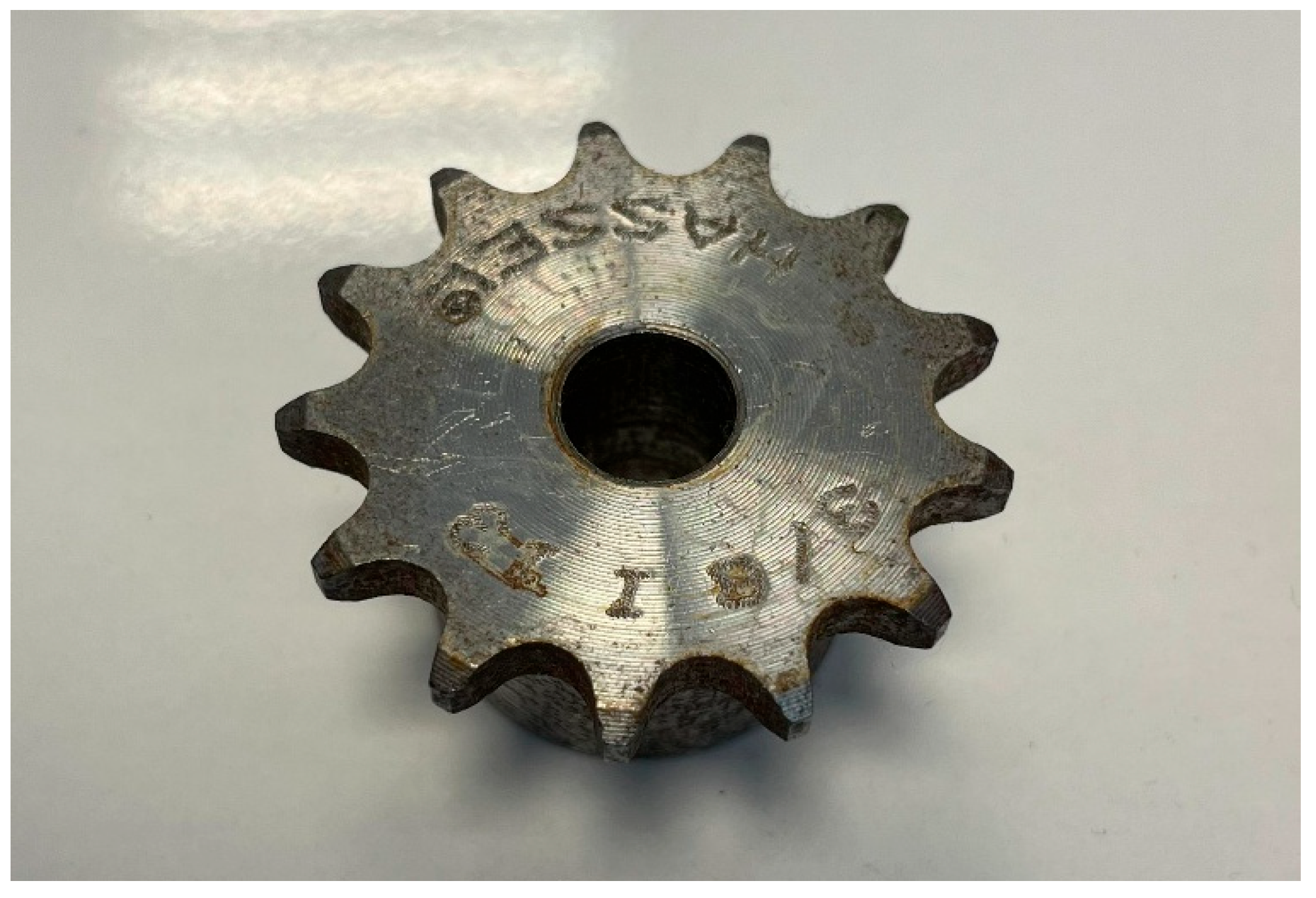
In the test phase after the system setup, the first test products were printed from PLA material with a 3D printer. In the next stage, sprockets were used as industrial actuators and are shown in
Figure 5. They were employed for testing an actual gear. The gear depicted in
Figure 5 is a commercially available steel gear, standardized according to DIN 867 [
26], and was used as a reference sample for image processing accuracy and sensitivity assessment. It was selected due to its standardized design and common availability in the market. For initial system calibration, simple test gears made of PLA material were used, followed by the steel sprockets to provide a representative industrial example (
Figure 5).
Thresholding is performed using Otsu’s method, which selects the threshold value
T that minimizes intra-class variance:
where
and
are class probabilities and
and
are the corresponding class variances.
The diameter is computed using the maximum Feret diameter:
where
and
are any two contour points of the detected object. This provides a robust geometric measure for gear dimension evaluation.
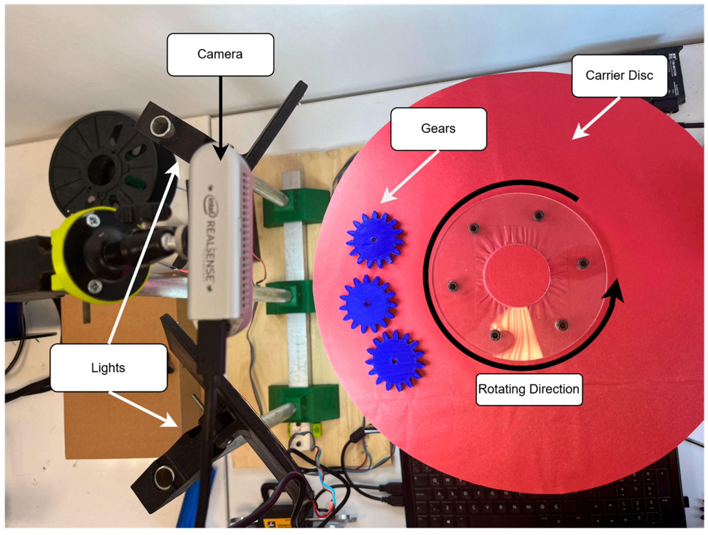
This system includes high-resolution lighting with a diffuser and a cross-type lighting method, fast image processing with an IPC featuring an Intel CPU, a product feeding unit, a rotary table product transport system with a stepper motor plexiglass optical table, a control for sorting valves via PC/MCU with locally designed electronic units, a machine vision system for monitoring products on the rotary table, and exit lines (roller conveyor lines). The stages can be seen in
Figure 6.
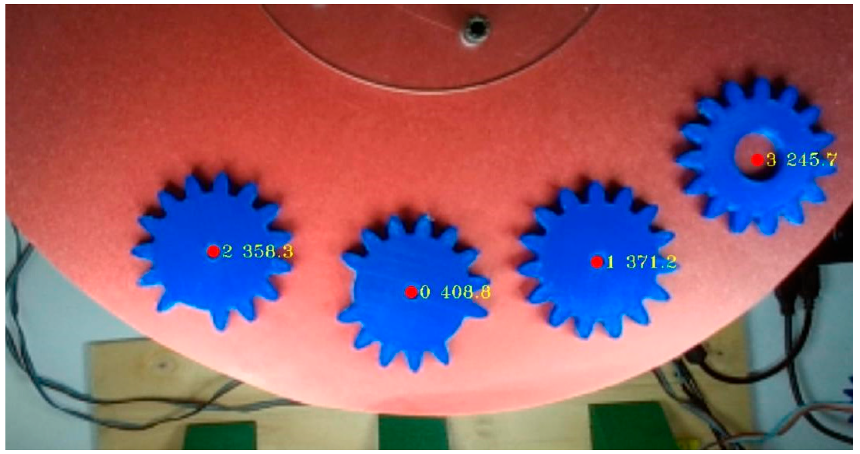
The first value in
Figure 7 indicates the detected object ID, while the second value represents the number of pixels used to determine the surface area of the gear. These values were obtained after the image processing procedures and reflect the total top-surface area of the gear in pixels.
3. Results and Discussion
In the experimental phase, the system was initially evaluated using 3D-printed gears to assess its classification accuracy, followed by testing with a chain gear. The digital models of the gears were created using Dassault Systèmes. (2024).
SolidWorks 2024 [Computer software]. Waltham, MA, USA. and subsequently converted into a stereolithography (STL) file format, suitable for additive manufacturing. The physical prototypes were produced from a PLA filament through fused deposition modeling (FDM), a commonly used 3D printing technique. A total of three defected gear samples were used for evaluation, equally distributed across three defect types: missing teeth, incorrect diameter, and surface irregularities. Each gear was tested 10 times under varying orientations and light conditions, resulting in 30 trials. The dataset was not split into training and validation sets due to the rule-based nature of the classification; however, future implementations with machine learning will adopt a structured training–validation–testing split. Evaluation metrics included accuracy, precision, recall, and F1-score, which are reported in
Table 1.
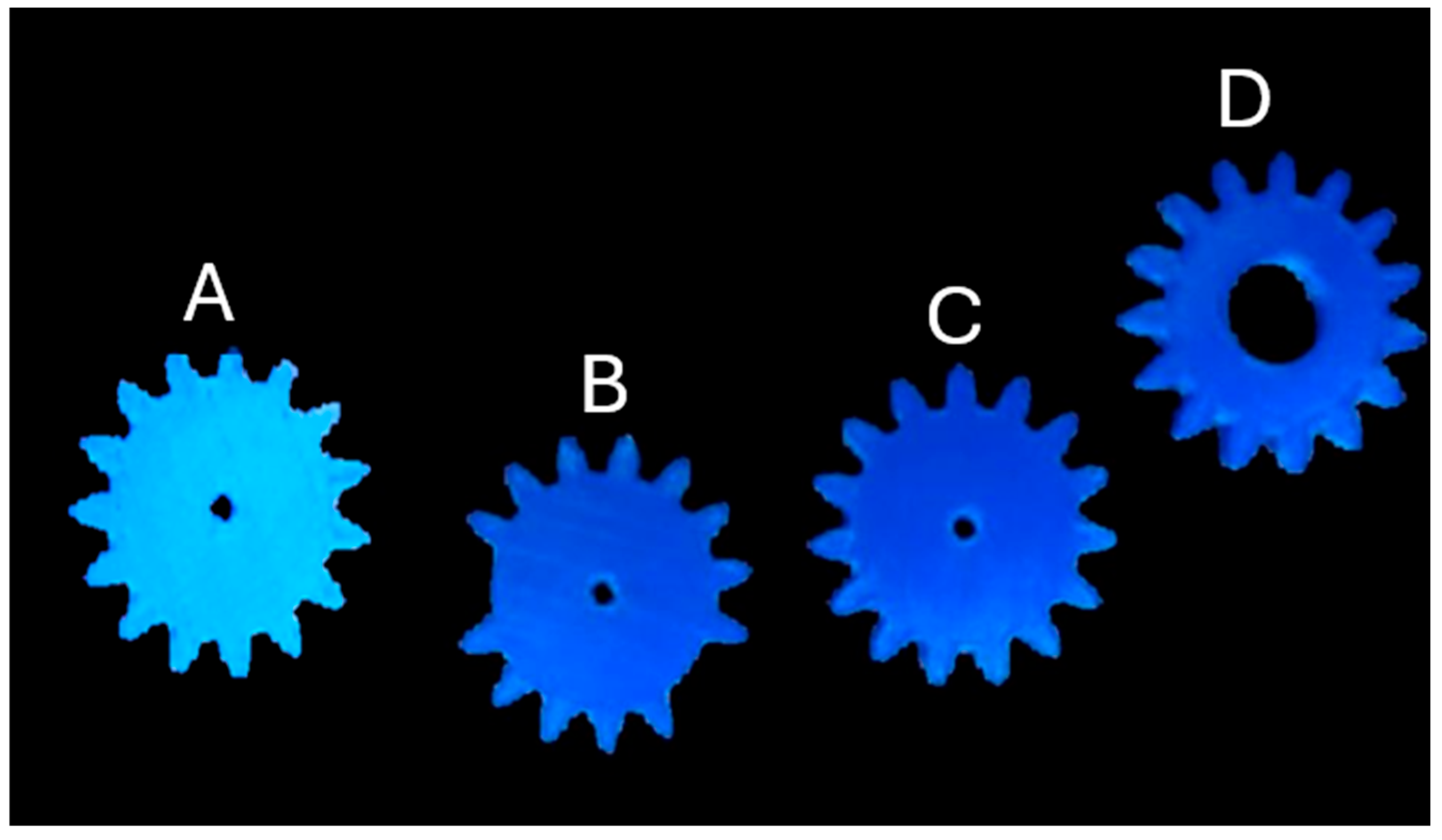
Figure 8 presents the masked images of both defective and perfect gears, in which the background has been effectively eliminated to improve visual clarity and facilitate detailed analysis. The gears employed in this study were blue in color, and the camera software was specifically calibrated to detect and isolate objects within this color range. To further enhance detection accuracy, the surface of the rotating table was covered with a dark, non-reflective material, thereby minimizing glare and optical interference. This setup enabled the vision system to capture high-resolution, well-defined images suitable for precise evaluation.
To assess the accuracy and consistency of the system, a structured testing protocol was implemented. As highlighted in previous studies on defect detection [
27,
28], image preprocessing and noise reduction play a vital role in improving the performance of machine vision systems. In this context, each of the four test gears was manually removed and repositioned on the rotating platform ten times. This repetitive procedure allowed for a thorough evaluation of the system’s stability and its ability to reliably detect and classify gear defects across varying orientations and placements. The findings confirm the system’s high degree of reliability and precision in identifying imperfections in gear profiles.
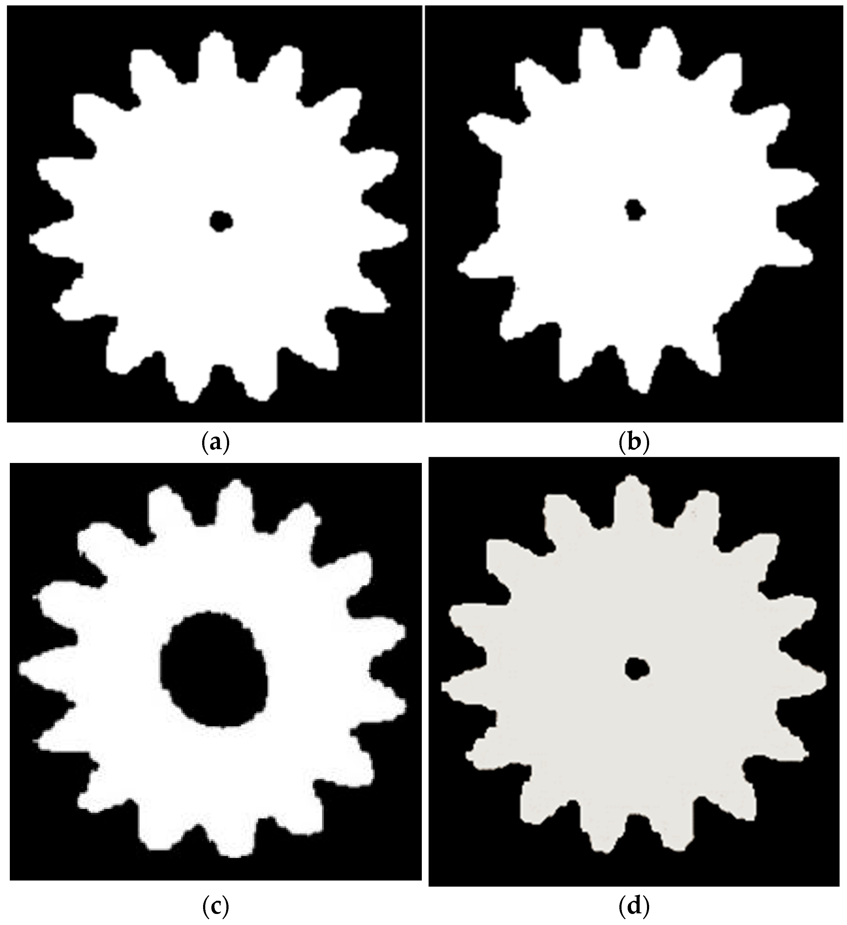
Figure 9 presents a thresholded, masked image in which each pixel is assigned a binary value ‘0’ corresponding to the background and ‘1’ to the gear object. This masking process serves to distinctly isolate the gear from its surroundings, ensuring a clear visual distinction that prevents blending with the background. To reduce potential noise and interference from ambient light sources, specific measures were taken to filter out extraneous visual data during image acquisition. The combined use of masking and thresholding, widely recognized in the literature as effective techniques for enhancing detection precision, has also been employed in related studies to improve classification accuracy [
13].
The system was calibrated to remain robust against such environmental disturbances. In order to assess its accuracy and repeatability, a series of controlled tests were conducted using four gears with differing features. Each gear was manually removed and repositioned on the rotating platform ten times, allowing for a systematic evaluation of the system’s ability to maintain consistent detection performance under variable positioning. The results demonstrate that the use of masked imagery significantly enhances the system’s sensitivity and enables the high-accuracy recognition of flawless gear components.
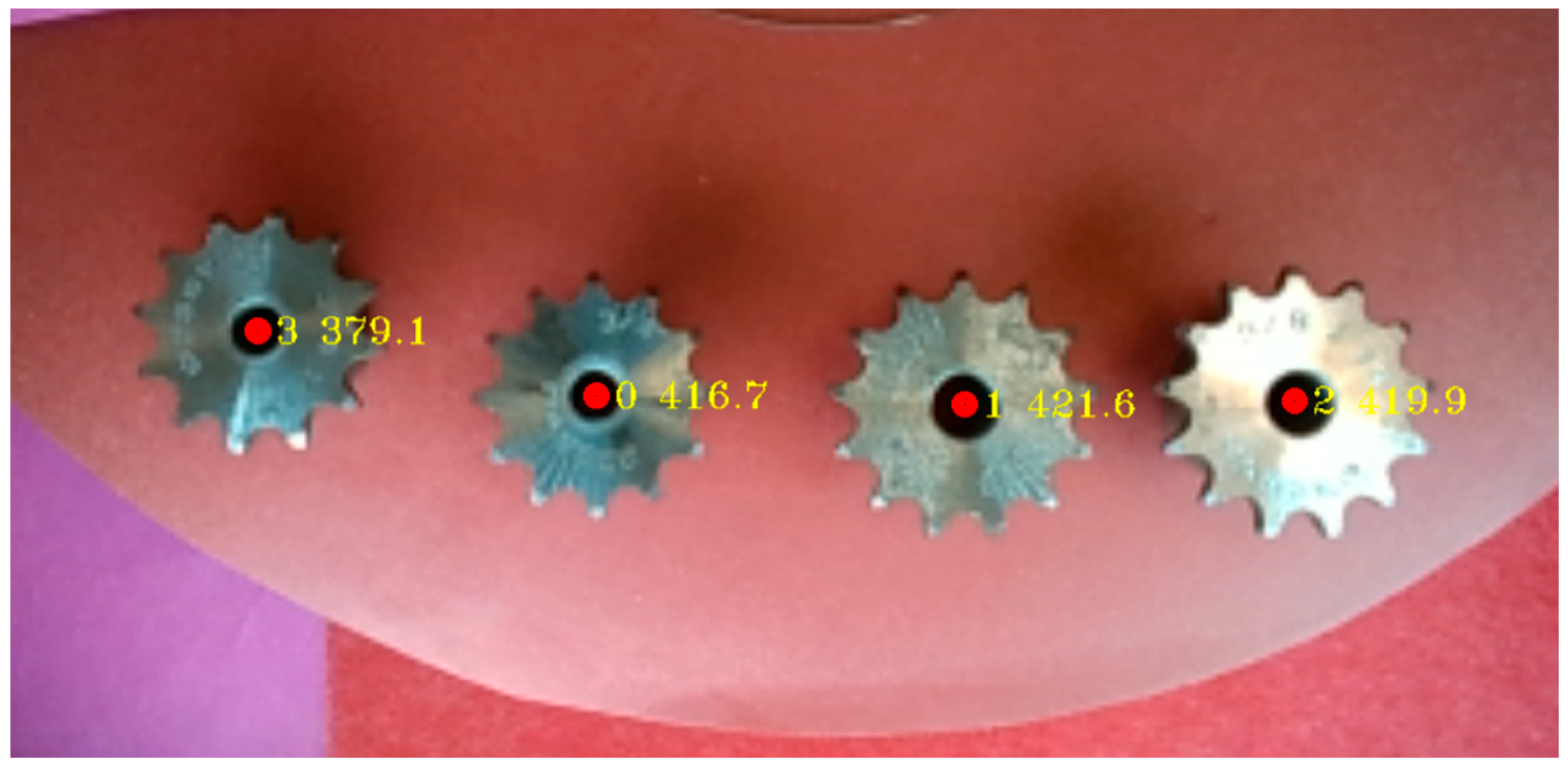
Figure 10 provides both visual and quantitative analyses of the area-based output parameters for defective and defect-free gears. The figure illustrates the calculated field values corresponding to each gear, which were meticulously assessed to identify and characterize surface and geometric defects. The analysis of imperfect gears indicates that typical flaws—such as missing teeth, surface irregularities, and dimensional deviations—significantly influence area measurements. To enhance measurement accuracy and eliminate potential interference from ambient lighting, the image acquisition process was conducted under controlled lighting conditions with appropriate isolation.
Each gear underwent individual testing, during which it was manually removed and repositioned on the rotating table ten times to assess the system’s repeatability. The results confirmed the system’s capacity to reliably distinguish between compliant and non-compliant gears. Furthermore, the statistical evaluation of the area outputs demonstrated a low error margin and high repeatability, underscoring the precision and robustness of the image-based inspection system.
The defective gear detection is based on pixel-area deviation, and is defined as follows:
Calculate the camera’s Field of View ()
Horizontal Field of View:
Vertical Field of View:
where
: focal length of the lens (mm);
: physical sensor width or height (mm);
: distance from camera to object (mm).
Pixel size determination is defined as follows:
where
: image width in pixels;
: image height in pixels.
Converting pixel area to actual area is performed as follows:
where
: area in pixels.
where
is the area of the detected gear, and
is the nominal area of a defect-free gear. The detection threshold was set empirically at ±3%.
Figure 11 depicts the defect rate observed in the tested gears, with a particular focus on the occurrence of missing teeth—one of the most critical faults impairing gear performance. This analysis offers valuable insight into the prevalence and spatial distribution of such defects along the production line, thereby supporting targeted enhancements in quality control procedures. To assess the repeatability and reliability of the defect detection system, a gear with known missing teeth was tested ten consecutive times under identical conditions. The results of these trials are presented in
Figure 12, which details the outcomes of each individual test, including variations in defect size, location, and other relevant characteristics.
A statistical evaluation of the repeated trials revealed that the standard deviation in defect detection remained consistently below 1%, indicating the high precision and strong repeatability of the system. This low variation highlights the robustness of the detection mechanism, demonstrating that the identification of missing teeth is stable and unaffected by external variables such as lighting conditions or minor differences in gear geometry. Such measurement consistency underscores the reliability of the system for industrial application [
29,
30]. The ability to consistently identify even subtle defects ensures that non-conforming gears are effectively removed from the production flow, thus reducing material waste, enhancing operational efficiency, and upholding high product quality standards.
Negative error values occur when the measured area is smaller than the nominal reference area, typically due to missing material (e.g., a broken tooth). These values reflect under-detection in area calculations and are expected in defective samples.
Figure 12 presents a detailed assessment of the classification accuracy and measurement consistency achieved by the system when evaluating defect-free gears. The analysis is based on ten repeated trials performed under identical conditions using a gear confirmed to be free of defects. Each test outcome is systematically reported, demonstrating the system’s capacity to reliably identify flawless components with a high degree of precision. The results show that the standard deviation across all trials remained below 1%, indicating negligible variability and confirming the consistency of the measurements.
This minimal deviation highlights the robustness and accuracy of the inspection process, ensuring that the classification of perfect gears is both consistent and resistant to random fluctuations or systematic errors. Such performance significantly reduces the risk of false-positive identifications, thereby reinforcing the credibility of the quality control process. The system’s ability to repeatedly validate defect-free gears with high accuracy supports its applicability in high-throughput industrial settings. By maintaining stable and precise inspection outcomes, the system contributes to improved production efficiency, reduced material waste, and the assurance that only components meeting quality standards proceed to subsequent manufacturing stages or end-use.
Negative error values occur when the measured area is smaller than the nominal reference area, typically due to missing material (e.g., a broken tooth). These values reflect under-detection in area calculations and are expected in defective samples.
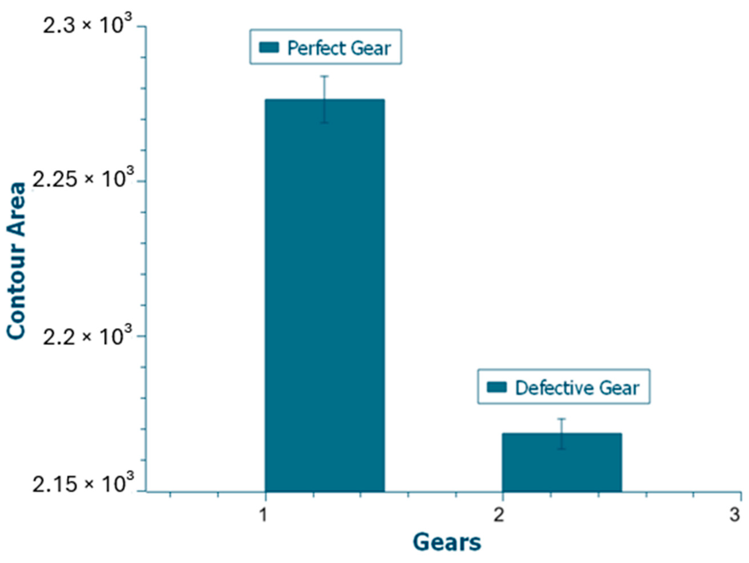
To assess the accuracy of the machine vision system (MVS) in distinguishing between defective and non-defective gears, two gear types were utilized during the experimental phase. Each gear underwent ten repeated evaluation cycles to generate a robust dataset for the repeatability analysis. The results, presented in
Figure 11 and
Figure 12 for defective and perfect gears, respectively, indicate that the standard deviation in both cases remained below 1%, reflecting a high level of measurement consistency. The mean difference between the two gear types was approximately 5%, demonstrating that the MVS is capable of effectively distinguishing between defective and faultless gears. A comparative summary of average values and standard deviations is illustrated in
Figure 13 and
Figure 14.
Initial tests were conducted using gears manufactured from PLA via 3D printing. Subsequently, more comprehensive evaluations were carried out using a chain sprocket gear to explore system performance in a more industrially relevant context. These tests focused on gears exhibiting common defects—such as missing teeth and dimensional inaccuracies—and compared their characteristics to those of defect-free samples. Advanced image processing and masking techniques were applied using a Visual Studio-based application, enabling the detailed examination of gear profiles. The processed images were captured and analyzed individually to assess the system’s defect detection capabilities.
To evaluate the influence of operational speed on detection performance, the chain sprockets were tested on a rotating platform at varying speeds. Each gear was placed sequentially, and the corresponding data were meticulously recorded. These trials were designed to verify the system’s ability to consistently identify defective gears while allowing flawless gears to continue along the production line without interruption.
Compared to previous systems reported in the literature [
15,
23,
24], the proposed machine vision system demonstrates superior performance in both accuracy and real-time operation. While existing recent solutions typically report detection accuracy performance between 88% and 91%, our system achieved 98.5% accuracy with a processing latency of only 42 ms per frame, enabling real-time defect removal without interruption. Furthermore, the implementation cost was kept minimal by using standard industrial components and open-source image processing libraries, making it more cost-effective and scalable for industrial environments.
Table 2 summarizes the comparative performance of the proposed system with previously published studies. Unlike tea leaf and fruit sorting systems that often rely on robotic arms or air-jet mechanisms with moderate accuracy and higher latency, our system achieves a higher accuracy (98.5%) and lower latency (42 ms) while maintaining a compact, cost-effective setup. The system also requires less mechanical complexity, which increases its applicability to various industrial contexts with minimal customization.
In the context of this study, deterministic rule-based algorithms were preferred over AI/ML/DL techniques due to several practical and operational advantages. First, deterministic methods provide faster and more predictable execution, which is essential for real-time applications with sub-60 millisecond latency requirements. Second, they are less computationally intensive and do not depend on large-scale labeled datasets, which are often difficult to obtain in industrial gear defect scenarios. Moreover, deterministic algorithms offer greater interpretability, facilitating easier debugging and validation—an important consideration in safety-critical manufacturing environments. These characteristics make rule-based logic particularly suitable for applications where system responsiveness and reliability are prioritized over the ability to learn complex but infrequent defect patterns.
The results confirmed that the MVS maintained consistent performance across different gear types and speeds. This aligns with previous studies on high-speed inspection systems, which similarly report stable performance under dynamic operating conditions [
30]. The integration of image processing and masking significantly enhanced the defect detection accuracy. Given its low error rates and high reliability, this system is well-suited for integration into high-throughput industrial production lines for real-time quality control [
11,
31]. The outcomes of this rigorous testing protocol validate the MVS as a reliable and precise tool for industrial defect detection applications.
Figure 15 displays the masked images of both defective and defect-free sprockets, with the background effectively eliminated to enhance image clarity. To accommodate the metallic surface characteristics of the test sprockets, the image processing software was specifically calibrated to detect and isolate this color range. The integrated camera system was configured accordingly to ensure accurate object recognition. Due to the reflective nature of the metallic sprockets, the surface of the rotating platform was covered with a dark, non-reflective material to minimize light interference and improve detection stability.
During the experimental procedure, each sprocket was tested in ten separate trials. For each trial, the sprocket was removed from the turntable and repositioned to assess the repeatability and reliability of the system under slightly varied positioning conditions. The results confirmed that the system consistently distinguished between defective and non-defective sprockets, producing highly accurate and repeatable measurement outputs. In addition, the tests revealed the sensitivity of the system to variations in lighting, while also demonstrating its robustness in compensating for such external factors through proper calibration and setup.
Figure 16 presents an image processed through thresholding during the image analysis phase, in which each pixel is assigned a binary value—‘0’ for the background and ‘1’ for the gear component. This binary masking technique was implemented to enable the system to reliably distinguish gear profiles from their background. To minimize the influence of ambient light and reduce image noise, the experimental setup included light isolation measures, ensuring that the vision system remained focused solely on the target object.
To assess the system’s accuracy and repeatability, a series of tests was conducted using three different gears. Each gear was manually removed and repositioned on the rotating table ten times to simulate varying placement conditions and evaluate detection consistency. This testing procedure was designed to examine both the precision and reliability of the machine vision system. The results confirmed that the system effectively processed the masked images and consistently identified the gears without error. As recognized in quality control applications involving polymer components, such high detection accuracy is essential for the reliable operation of automated inspection systems [
8].
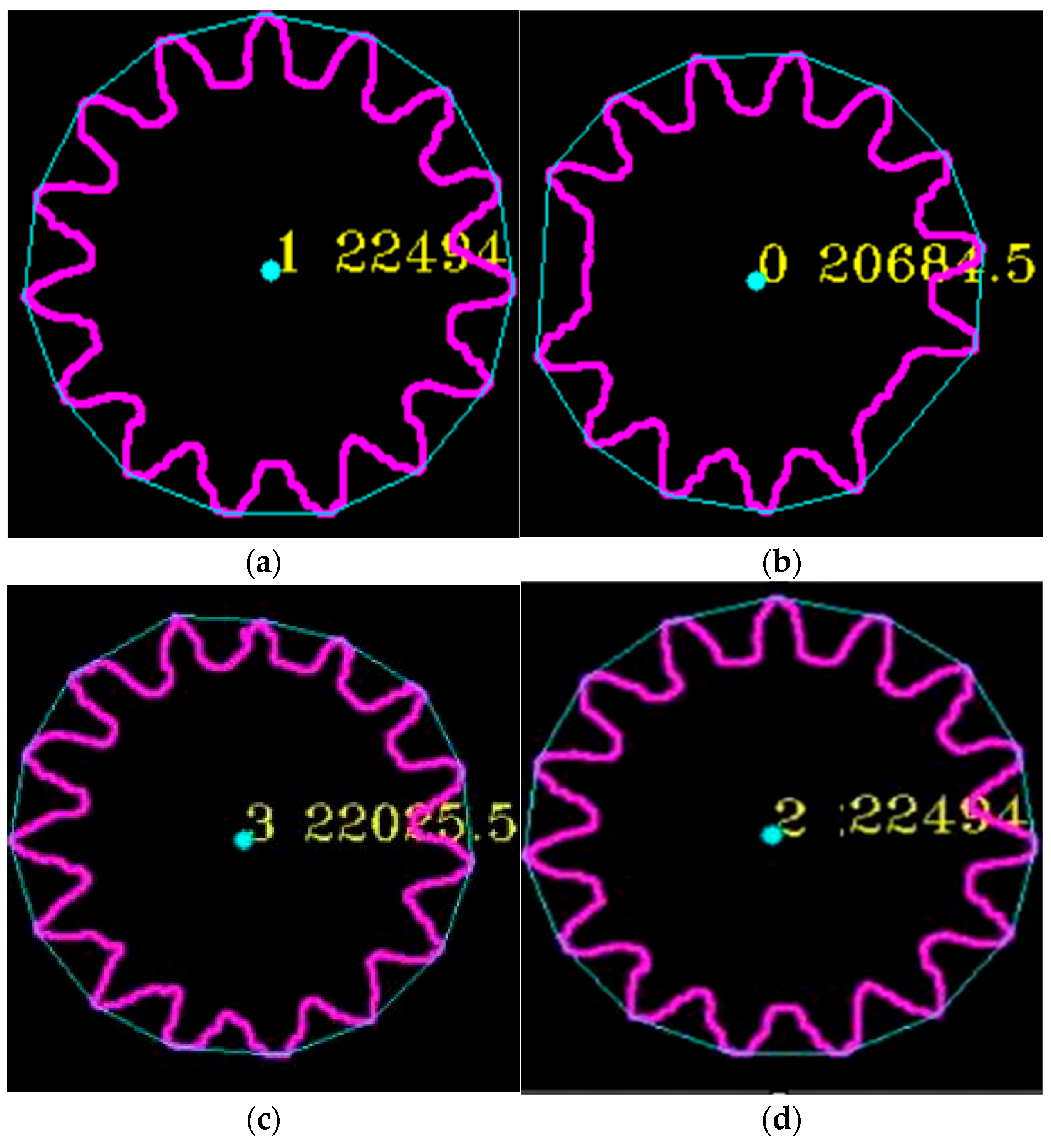
Figure 17 provides both visual and quantitative analyses of the area (field) measurements obtained from defective and defect-free sprocket samples. The figure presents detailed field values, which were analyzed to detect and quantify defects such as missing teeth, dimensional inaccuracies, and other common anomalies. This analysis clearly demonstrated that these defects have a significant impact on the calculated field values. To ensure measurement accuracy and eliminate the effects of ambient lighting, the image processing system was operated under controlled lighting conditions with appropriate isolation.
For each sprocket, a series of ten repeated tests was conducted, involving the removal and repositioning of the sprocket on the rotary table. The resulting measurements validated the system’s ability to accurately recognize sprockets and reliably detect defects. The statistical evaluation of the field data revealed a very low error margin and high repeatability, confirming the robustness of the system. These outcomes indicate that the proposed setup holds considerable potential for enhancing quality control practices in sprocket manufacturing.
In addition to static condition testing, the system’s performance was also assessed under dynamic conditions by varying the speed of the rotary platform. The motor speed was incrementally adjusted across five levels, ranging from slowest (level 1) to fastest (level 5). At each speed setting, five tests were conducted using both defective and defect-free sprockets, resulting in a total of twenty-five trials. The error rate across all tests remained below 1%, further demonstrating the system’s reliability and accuracy in high-speed inspection scenarios. The use of masked imaging and refined image processing techniques contributed significantly to the accurate classification of the sprockets, highlighting the suitability of the system for real-time quality control in industrial applications.
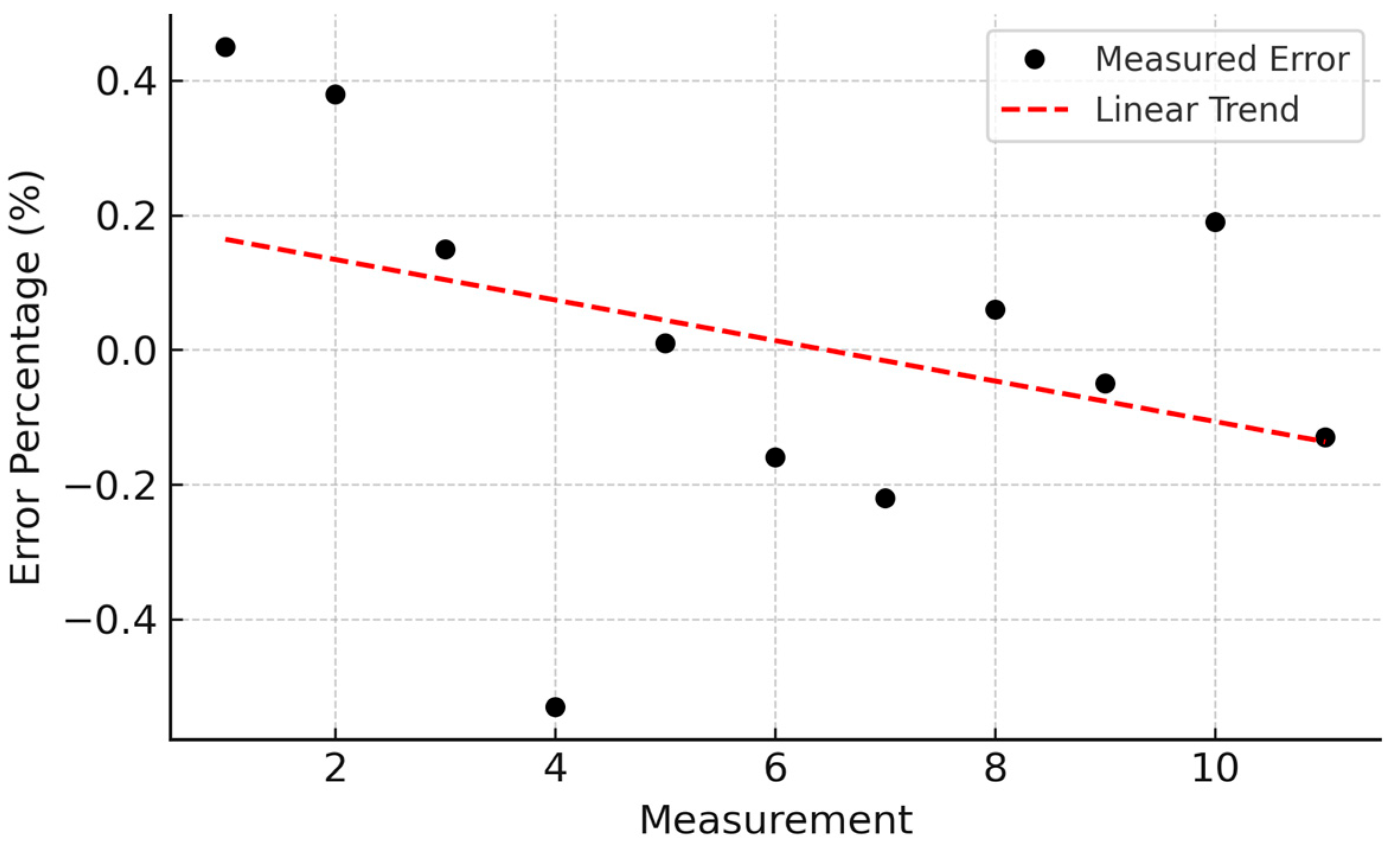
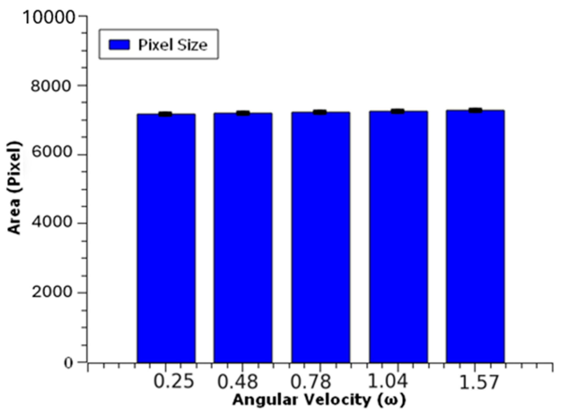
Figure 18 illustrates the performance of the defect-free chain sprocket tested across five distinct rotational speed settings: 0.25, 0.48, 0.78, 1.04, and 1.57 rad/s. During each speed phase, the gear was positioned identically on the rotary table and tested five times under the same conditions, enabling an assessment of the system’s consistency under dynamic operating scenarios. For every speed level, the average pixel area of the gear was computed from the acquired images, and corresponding error rates were calculated. The recorded average pixel values were 7387, 7380, 7403, 7079, and 7073 pixels, respectively. These results indicate that the system maintains a high level of consistency despite changes in rotational speed.
To further quantify the system’s precision, error bars were calculated for each dataset and are depicted in
Figure 18. The respective error rates across the five speed phases were found to be 0.63%, 0.79%, 0.93%, 0.93%, and 0.76%, all remaining below 1%. This low level of variability confirms the system’s ability to perform with high accuracy across varying speeds and repeated trials. The outcomes suggest that the system functions robustly under real-world production conditions, remaining unaffected by fluctuations in lighting, positioning, or rotation speed. The consistency observed across all test conditions underscores the system’s reliability and reinforces its suitability for deployment in industrial quality control environments where processing speeds may vary [
3].
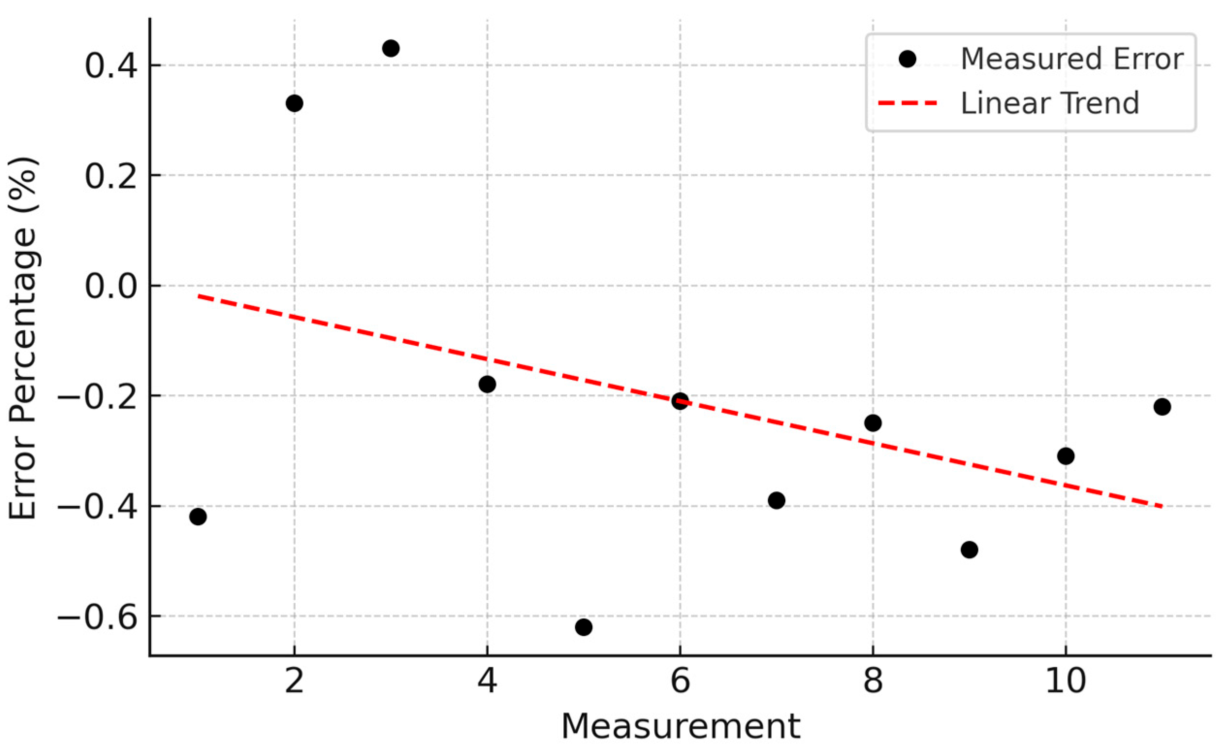
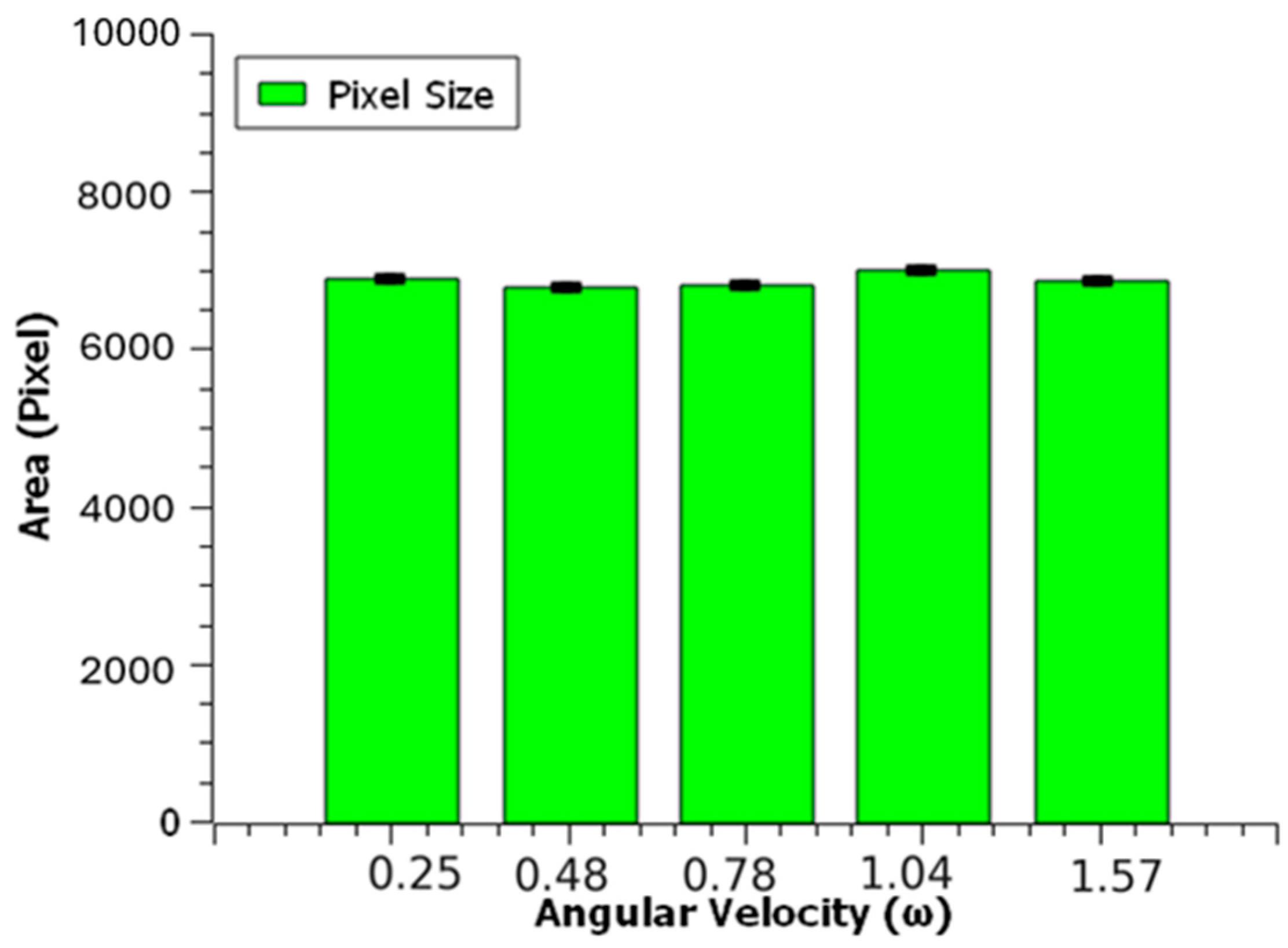
Figure 19 illustrates the performance evaluation of a defective chain gear—characterized by a missing tooth—across five rotational speed settings: 0.25, 0.48, 0.78, 1.04, and 1.57 rad/s. For each speed level, the gear was positioned identically on the rotary table and subjected to five repeated trials under the same conditions, allowing for a systematic assessment of the system’s consistency under dynamic conditions. The average pixel area of the gear was computed for each speed phase based on the captured images, with the following values recorded: 6878, 6764, 6812, 6999, and 6868 pixels, respectively. These results indicate that the system maintained consistent detection performance despite variations in rotational speed.
Error bars were calculated for each dataset and are presented in
Figure 19. The corresponding error rates for each speed level were determined to be 0.46%, 0.45%, 0.74%, 0.64%, and 0.62%, all remaining well below 1%. These low error margins confirm the system’s high degree of precision and reliability, not only under differing speed conditions but also across multiple repetitions. Overall, the findings demonstrate that the vision system is robust against potential sources of variability such as lighting, object positioning, and speed fluctuations, thereby validating its suitability for deployment in real-time industrial inspection scenarios.
Figure 20 illustrates the performance assessment of a chain gear exhibiting a faulty pitch, tested across five distinct rotational speed settings: 0.25, 0.48, 0.78, 1.04, and 1.57 rad/s. At each speed level, the defective gear was placed in a consistent position on the rotary table and subjected to five repeated trials under identical conditions, enabling a detailed evaluation of the system’s stability under varying operational speeds. The average pixel area of the gear was calculated from the captured images for each speed phase, yielding values of 7162, 7177, 7217, 7225, and 7265 pixels, respectively. These results indicate a consistent performance across different speeds.
Error bars were computed based on the recorded data and are presented in
Figure 20. The corresponding error rates for each speed were calculated as 0.34%, 0.61%, 0.63%, 0.56%, and 0.44%, all remaining well below 1%. These minimal error margins confirm the system’s high accuracy and repeatability, both under variable speed conditions and across multiple test repetitions. The findings further demonstrate that the system operates reliably and is resilient to external factors such as lighting fluctuations, object positioning, and rotational velocity. This consistency reinforces its applicability for robust, real-time quality control in industrial production environments. Performance benchmarking revealed that the system could process an average frame in 42 milliseconds, corresponding to approximately 24 frames per second (FPS). The latency from image capture to pneumatic actuation was under 60 milliseconds, which is sufficient for real-time operation at typical conveyor speeds. A detailed speed test across five different rotation rates confirmed that the error rate remained below 1% regardless of operational speed. These results validate the system’s suitability for high-throughput manufacturing environments.
4. Conclusions
This study focused on the development and implementation of an automatic gear separation system for use on a production line. The system is composed of a rotary table, a high-resolution machine vision system (MVS), computer-based image processing software, and a pneumatic separation mechanism.
The developed system successfully passed a series of testing and calibration procedures. The camera and image processing software reliably detected defects such as missing teeth, surface irregularities, and incorrect gear dimensions with high precision. The pneumatic valve operated as intended, effectively removing defective gears from the rotary table and ensuring that only compliant components continued along the production line.
During the experimental phases, the system consistently differentiated between defective and non-defective gears, demonstrating both detection accuracy and mechanical reliability. Repeated trials under varying operational conditions, including different gear types and rotational speeds, confirmed the system’s robustness, with all error rates remaining below 1%. This indicates a high degree of repeatability and measurement stability.
In conclusion, this study presents a practical and efficient solution for automating quality control in manufacturing environments. The proposed automatic gear separation system contributes to enhanced production line efficiency and improved product quality by preventing the progression of defective components to subsequent assembly stages. The system demonstrated consistent performance not only under static test conditions but also across variable speed settings, confirming its suitability for real-time applications in dynamic industrial workflows.
Moreover, the use of masked imaging and threshold-based segmentation techniques significantly improved defect detection performance, while the low standard deviations observed across all test scenarios validated the reliability of the system’s image-based classification approach.
Although the proposed system achieves a response time below 60 milliseconds, it is acknowledged that certain complex or ambiguous defects may not be captured by the current rule-based approach. However, the chosen thresholding and geometric feature extraction methods were specifically tuned to the most commonly encountered and structurally impactful defects, such as missing teeth and dimensional deviations. Furthermore, controlled lighting and masking techniques were employed to enhance the clarity of visual features. Future work will explore hybrid models that combine deterministic speed with the adaptive capacity of AI models to address more subtle and less frequent defect patterns without compromising response time.
The limitations of this study include the reliance on threshold-based binary classification, which may underperform in detecting complex or subtle defect patterns. Additionally, the dataset was limited to synthetic PLA gears and chain sprockets, which may not fully represent variability in real industrial settings. Future work will address these limitations by integrating deep learning-based classifiers and testing on diverse industrial samples.
While deep learning methods offer high classification potential, this study prioritized deterministic algorithms to ensure real-time processing with minimal hardware requirements. This choice was also influenced by the limited size of available labeled datasets. Nevertheless, the system is designed to be expandable for future CNN-based integration.


