Abstract
An electro-hydraulic servo system based on network control technology has the advantages of remote control, modularisation, and resource sharing. However, the electro-hydraulic servo system itself has the characteristics of strong nonlinearity and parameter uncertainty, combined with the limited communication bandwidth of the network control system, which leads to a poor control effect and limits its application. To solve the above problems, an event-triggered mechanism is introduced to filter redundant data and conserve the communication bandwidth, while a backstepping sliding mode control strategy integrating this event-triggered mechanism with a jamming observer is proposed. A model-based disturbance observer is designed to mitigate external interference effects on system control performance while enhancing robustness and disturbance response capabilities. The global stability of the closed-loop system is analysed using Lyapunov stability theory. The experimental results show that the system displacement tracking error of the controller designed in this paper can reach ±0.001 rad, and the system can reach stability in about 0.5 s. At the same time, it can significantly reduce the amount of data transmission, which effectively solves the problem of the network bandwidth limitation.
1. Introduction
Electro-hydraulic servo systems [1] are one of the core technologies of mechatronic engineering, with the characteristics of high power, rapid action, and accurate response. They are used on a large scale in aviation, automation equipment, and industrial robots. In the early twentieth century, precise control of ships’ heading was achieved by precise hydraulic manoeuvring, which marked their initial use in the military field. With the development of science and technology, especially the rapid progress of electronic technology, electro-hydraulic servo systems are constantly being upgraded and improved, and their importance in various types of automatic control systems is becoming increasingly prominent. In recent decades, electro-hydraulic servo systems have not only been expanded in the aerospace field, but also gradually popularised in military and civil industries. With the increasing requirements for control and safety performance, electro-hydraulic servo systems have been optimised to integrate more advanced sensors and intelligent control algorithms to improve their performance and reliability. Network control technology has attracted great attention because of its advantages of remote control, resource sharing, easy installation, etc. These features have a high degree of fit with the development needs of electro-hydraulic servo systems. Therefore, considering the many advantages of network control technology and combining the advantages of the hydraulic system itself, the combination of electro-hydraulic servo and network control technology has very broad research and application prospects.
However, in the framework of network control, the stability of the system [2] can be undermined by problems such as packet loss and delay caused by the limitation of the communication bandwidth. Therefore, understanding how to improve communication bandwidth utilisation has become one of the main directions in the study of network-controlled communication systems. Deng et al. [3] proposed a periodic event-triggering strategy for linear systems to reduce the amount of communication data. Wang et al. [4,5] proposed fuzzy adaptive event-triggering and distributed hybrid event-triggering schemes to regulate the output signals. In Yin et al.’s study [6], an internal dynamic variable is introduced into the static event-triggering mechanism, a dual-channel dynamic event-triggering mechanism is designed, and a model-based network predictive control method is proposed to actively compensate for the delay of the dual-channel network. Gu et al. [7] designed a new event-driven control strategy to solve the denial-of-service attack problem and calculate the maximum value of system performance loss. Shen [8] combined the event trigger mechanism with the network system, reducing network bandwidth pressure while ensuring control performance. Sun et al. [9] proposed an event-triggered strategy for systems with quantisation and time delays. Shen [10] combined an event-triggered mechanism with a hydraulic system, removing a large amount of redundant data while ensuring the control performance. In fact, event-triggered strategies have been widely used in practice. In systems such as vehicle-specific networks, researchers have found that event-triggered strategies effectively mitigate communication traffic.
Electro-hydraulic servo systems are typically strongly nonlinear time-varying systems with parameter uncertainties and unknown unmodelled external disturbances, which increase the difficulty of developing high-performance tracking controllers. In order to solve the above problems, some advanced control strategies have been proposed by researchers. Hou et al. [11,12] proposed a control strategy based on an iterative learning algorithm, which effectively improves the control performance of the system. Jing et al. [13] proposed an algorithm for the adaptive non-singular terminal sliding mode, which improves the robustness of the system. For systems with uncertain model parameters and external disturbances, some scholars have proposed disturbance observers, high-gain disturbance observers, etc., to estimate the composite disturbances in finite time. Yu et al. [14] combined backstepping and adaptive control to avoid high-yield feedback and improve the tracking effectiveness of the system. However, all of the above control strategies require velocity information, a requirement that is difficult to fulfil in electro-hydraulic servo systems due to the limitations of velocity sensor applications. One of the methods to indirectly obtain the velocity signal is to obtain the velocity by calculating the differential of the displacement, which has the disadvantages of inaccurate velocity estimation at a fixed finite gain and a high-gain peaking effect. The above-mentioned scholars have investigated control strategies for nonlinear systems and improved their control performance.
The combination of network control technology and electro-hydraulic servo systems has not been investigated in the above literature, whereas in this paper, network control technology is combined with electro-hydraulic servo systems to consider how to effectively improve the utilisation of the communication bandwidth of the network system while focusing on problems such as parameter uncertainty and uncertain external disturbances that exist in the electro-hydraulic servo system itself [15,16,17]. A backstepping sliding mode control strategy based on event triggering and a disturbance observer is proposed. An event-triggering mechanism is introduced during the controller design process to filter a large amount of data and thus improve the communication bandwidth utilisation. The unknown external disturbances of the system are estimated by a disturbance observer, which reduces the role of sensors. At the same time, the actual measured displacement signal is replaced with the corresponding desired signal value and substituted into the observer to reduce the noise interference and improve the tracking control performance.
The research in this paper is organised as follows: in the second part, the mathematical model of the electro-hydraulic servo pump control system is presented and the state-space expression of the system is established to facilitate the design of the subsequent controllers; in the third part, the event-triggering mechanism used in this paper is introduced, and the model of the disturbance observer, as well as the backward-stepping sliding mode controller based on the disturbance observer, is derived and verified for stability; in the fourth part, simulation experiments are performed; and in the fifth part, the conclusions are drawn.
2. Mathematical Model of Electro-Hydraulic Servo Pump Control System
This section describes the operating principle and mathematical model of the electro-hydraulic servo pump control system and derives the space equation of state of the system.
2.1. Electro-Eydraulic Servo Pump Control System
The electro-hydraulic servo pump control system is, on account of the servo motor, quantitative pumps, hydraulic cylinders, and functional valves, a highly integrated volume servo control unit, where the servo motor speed and torque can be adjusted, the system pressure and flow can be changed, and the hydraulic cylinder actuation output can be controlled. Compared with a traditional valve control system, this system eliminates the huge hydraulic station, complex pipelines, and expensive servo valves, effectively overcoming the poor anti-pollution ability, low integration, serious energy wastage, and other inherent technical shortcomings of electro-hydraulic servo valve control technology, offering high energy efficiency and energy savings, a high power-to-weight ratio, and environmental friendliness, among other technical advantages. The working principle diagram of the electro-hydraulic servo pump control system is shown in Figure 1.
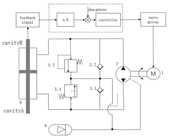
Figure 1.
Working principle diagram of electro-hydraulic servo pump control system.
In the figure, the electro-hydraulic servo pump control system adopts the drive mode of the servo motor (1) and hydraulic pump (2) coaxial direct connection, and the inlet and outlet ports of the hydraulic pump are directly connected to the two chambers of the hydraulic cylinder (6). The accumulator (4) has check valves 3.1 and 3.2 for oil replenishment, and safety relief valves 5.1 and 5.2 to ensure that the system pressure does not exceed the safety threshold. The system regulates the output flow of the hydraulic pump by precisely controlling the rotational speed or torque of the servomotor to achieve precise control of the piston displacement or output pressure of the hydraulic cylinder.
Within the pump control system in the position control process, the servo motor will control the input voltage for the motor output speed. We consider the servo motor to have a high response speed and control accuracy. The relationship between the motor output speed and the input control signal can be simplified as a proportional link, which is expressed as follows:
where is the input speed of the dosing pump, is the control gain, and is the control input signal.
2.2. Dosing Pump Model
Taking into account factors such as oil compression and internal and external leakage, the two-chamber load volume flow rate from the pump to the hydraulic cylinder being controlled can be expressed as
In the formula, and are the quantitative pump output and suction flow; is the quantitative pump displacement; and are the pump outlet and inlet pressures; and and are the internal and external leakage coefficients of the pump.
The flow continuity equation for the hydraulic cylinder A and B chambers is
In the formula, and are the flow into the hydraulic cylinder A cavity and flow out of the B cavity; and are the effective volumes of the hydraulic cylinder A and B cavities; is the effective working area of the hydraulic cylinder; is the output displacement of the hydraulic cylinder; is the effective volume modulus of elasticity; and and are the pump’s inside and outside leakage coefficients.
From Equations (2) and (3), we have
where = + + + /2 is the total leakage factor of the system, and is the total compressed volume.
The force balance equation for the piston rod of the hydraulic cylinder is
In the formula, is the equivalent total mass of the hydraulic cylinder piston; is the viscous damping coefficient of the system fluid; K is the equivalent spring stiffness of the system load; and F is the load force on the hydraulic cylinder piston.
2.3. Electro-hydraulic Servo Pump Control System State-Space Expression
By selecting the system state vector xc, the piston rod displacement, as the state variable, can be obtained:
The following state-space expression can be obtained from Equations (1–6):
where , is the mismatched model uncertainty of the system, including external load disturbances, non-modelled friction, and non-modelled dynamics, and is the pressure dynamic modelling error, i.e., the matched model uncertainty of the system.
3. Design of Backstepping Sliding Mode Controller Based on Event Triggering and Perturbation Observer
In this section, to address the model uncertainty, external perturbation, and resource limitation faced by nonlinear systems, this paper proposes a backstepping sliding mode control strategy based on an event-triggering mechanism and a perturbation observer. The recursive control law is constructed using the backstepping method and combined with sliding mode control to enhance the robustness; the disturbance observer is used to estimate and compensate the disturbance in real time to reduce jitter; and the event-triggered mechanism is introduced to reduce the frequency of controller update and save computational resources. The stability of the closed-loop system is proved by Lyapunov theory.
3.1. Event-Triggering Mechanism
In order to reduce the consumption of communication resources and achieve better system performance, this paper adopts a non-fixed period sampling strategy. Let k be the current sampling time instant, and be the most recent release time instant occurring at a sampling time before k. Then, denotes the current state of the system, and denotes the system state of the last successful transmission in the network.
The event trigger condition is defined as
where are the event trigger coefficients.
Zeno behaviour has a very large impact on systems with event-triggering mechanisms. To avoid Zeno behaviour, the output period of the controller is set to be larger than the minimum time interval between adjacent triggers of the event trigger.
3.2. Design of the Perturbation Observer
In control systems, there are significant differences in the mechanisms by which external disturbances and observer errors affect stability. External disturbances act directly on the controlled object, and their impact depends on the amplitude–frequency characteristics of the disturbance: low-frequency disturbances mainly cause steady-state shifts, medium-frequency disturbances lead to deterioration of the dynamic performance, and high-frequency disturbances may stimulate unmodelled dynamics of the system. The effect of observer error is more complex, as it not only equates to additional disturbances, but also creates secondary perturbations through the control loop. Especially in backstepping sliding mode control, the observer error is amplified step by step during the recursive design process and interacts with the sliding mode switching gain to significantly enhance the jitter phenomenon. When the two are coupled, a compound disturbance is formed, the energy of which may exceed the uncertainty bounds considered in the controller design, resulting in the Lyapunov function no longer being negatively determined and threatening the system stability. The perturbation observer used in this paper is a design concept used to eliminate the effect of external disturbances on the control performance of a system, to increase the robustness of the system, and to improve the responsiveness to external disturbances. A nonlinear disturbance observer is used as a control strategy to estimate and compensate for unknown disturbances in nonlinear systems. The advantage of the perturbation observer is that it can handle a variety of unknown disturbances, including model uncertainty and parameter variations, thus improving the stability and performance of the system. The nonlinear disturbance observer improves the performance of the control system in an uncertain environment through accurate disturbance estimation and compensation. The disturbance observer used here is based on the state observer composition.
For the state quantity and the mismatch perturbation , define the error as
where and are the observed values of and , respectively.
The perturbation observer is designed:
where is the gain of the observer.
The state estimation error is
where is the rate of change of the mismatch perturbation.
For the state quantity and the mismatch perturbation , define the error as
where and are the observed values of and , respectively.
The perturbation observer is designed:
where is the gain of the observer.
The state estimation error is
where is the rate of change of the mismatch perturbation.
3.3. Backstepping Sliding Mode Controller Design
The backstepping sliding mode control method is an advanced nonlinear control strategy combining backstepping and sliding mode control, which is mainly applied to complex nonlinear systems with strict feedback forms. The core idea of the method is to decompose a high-order system into multiple low-order subsystems through the recursive design framework of backstepping, gradually construct the virtual control quantities, and design the corresponding Lyapunov functions, so as to ensure the stability of each subsystem, and ultimately achieve global stable control of the whole system. The sliding mode control mechanism is introduced in the final design stage of the control law, by defining a suitable sliding mode surface and adopting a discontinuous switching control strategy, so that the system state can converge to the sliding mode surface in a finite period of time and keep the motion on the surface, thus endowing the control system with a strong robustness against parameter uncertainty and external disturbances.
The desired trajectory is , introducing an error:
Define the Lyapunov function as
The derivative of can be obtained as
To make , define the desired trajectory and introduce the error as
where is a number greater than 0. The derivative of can be re-expressed as
The derivative of the virtual control term is
Define the Lyapunov function as
The derivative of can be obtained as
To make ≤ 0, define the desired trajectory and introduce the error as
where is a number greater than 0. The derivative of can be re-expressed as
The sliding mode surface is defined as
where and are constants satisfying Hurwitz. The Lyapunov function is defined as
The derivative of can be obtained as
The control law u can then be obtained:
where and are constants greater than zero.
Substituting the control law u into , we get
where is the maximum observation error of the observer.
If the matrix is guaranteed to be positive definite, then there is
The parameters in the controller are chosen to satisfy the following inequality:
Then, it is guaranteed that the matrix is positive definite, at which point
Obtainable:
As the error of the observer gradually converges to zero, i.e., , at which point , it is therefore possible to obtain , , , then ; i.e., the system can reach stability.
4. Simulation Experiment
To verify the effectiveness of the backstepping sliding mode controller designed in this section, simulation experiments were carried out in Simulink. The inverse step sliding mode controller is compared with a PID controller and sliding mode controller in the simulation experiments. The PID controller is a classical control algorithm widely used in industrial control systems, and the sliding mode controller is a commonly used method in the control of electro-hydraulic servo systems in recent years, so it is a good choice to compare these three control methods, allowing us to determine whether the proposed control method is effective or not. The parameters of the electro-hydraulic servo system used are shown in the below Table 1.

Table 1.
Electro-hydraulic servo system parameters.
The values of the parameters of the backstepping sliding mode controller are , , , , , , , and .
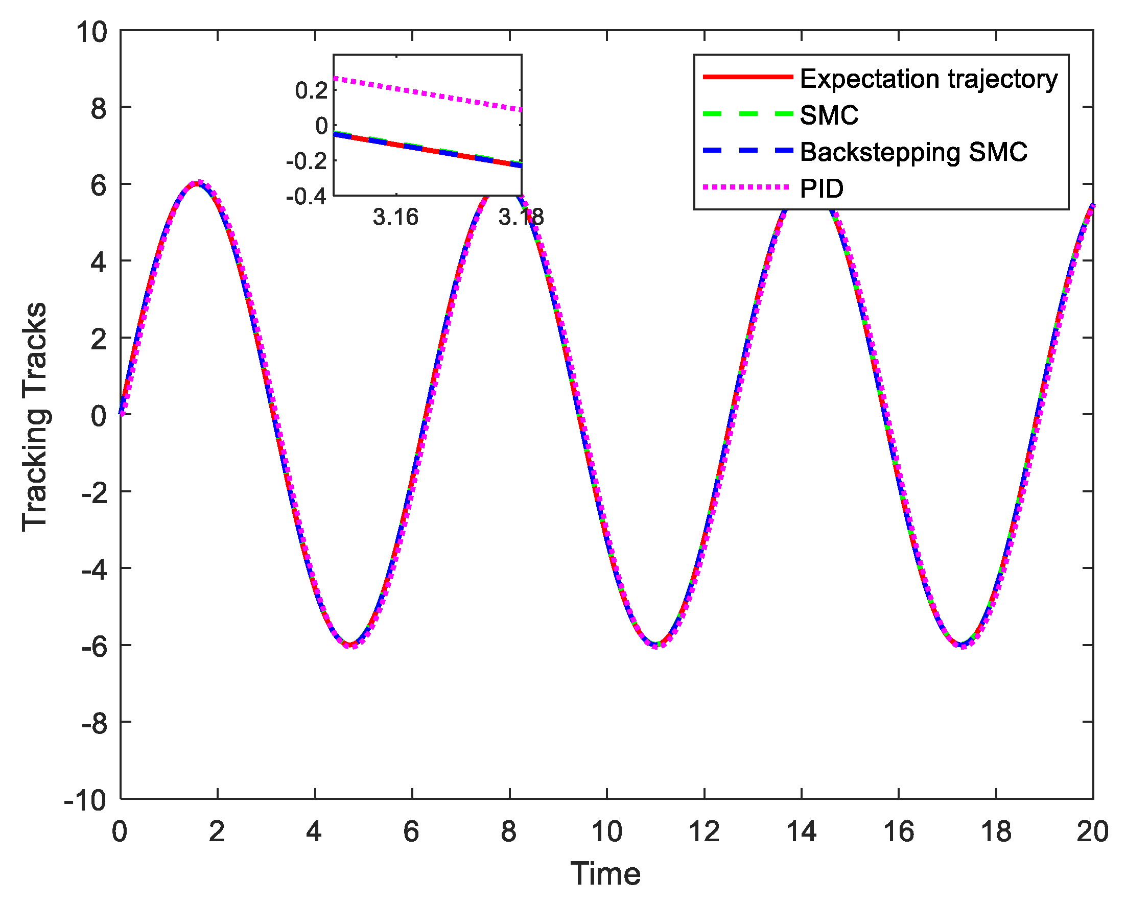
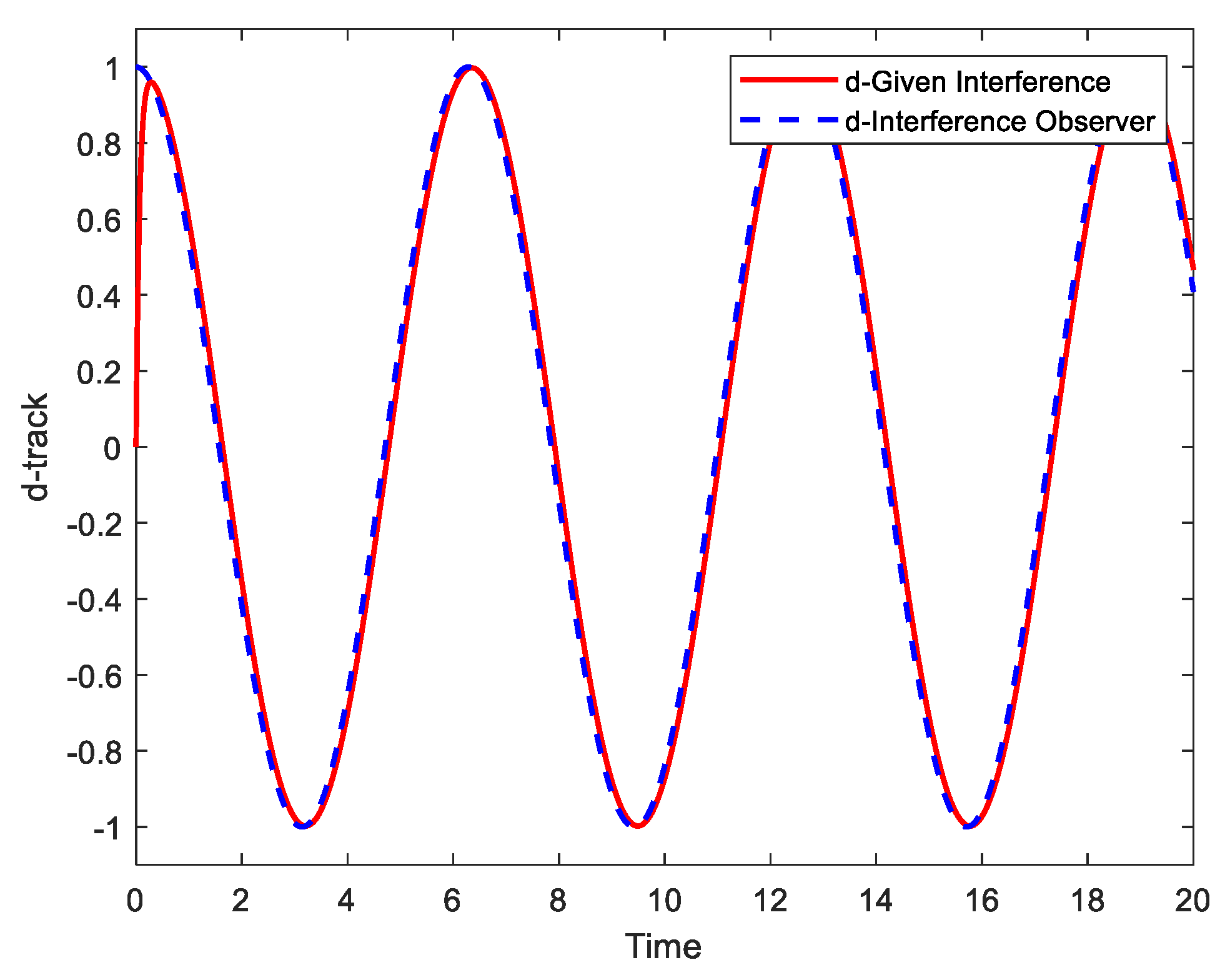
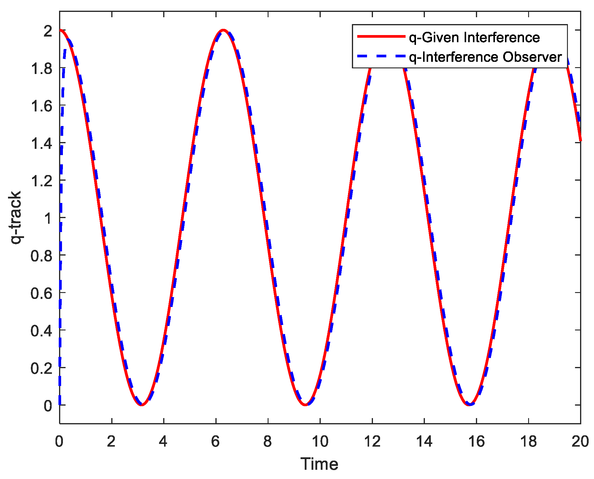
Experiment 1: The sinusoidal signal is selected as the control target, and perturbations and are and , respectively. The tracking performance of the above three controllers under the same conditions is shown in Figure 2, and the tracking error curves are shown in Figure 3. The observations of the perturbation observer are shown in Figure 4 and Figure 5.
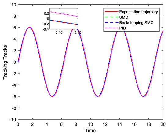
Figure 2.
Comparison of the tracking effect of the three controllers.
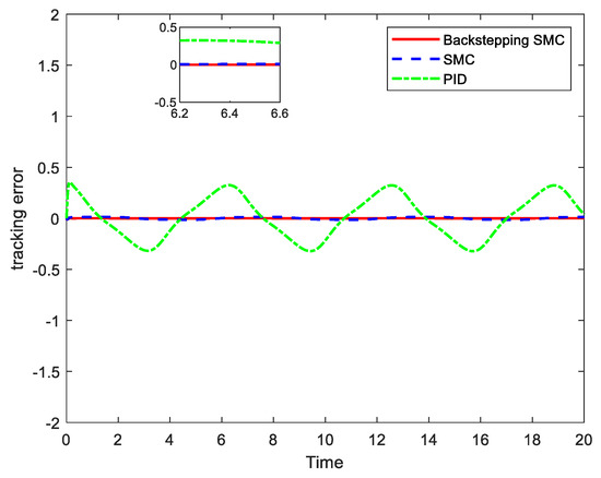
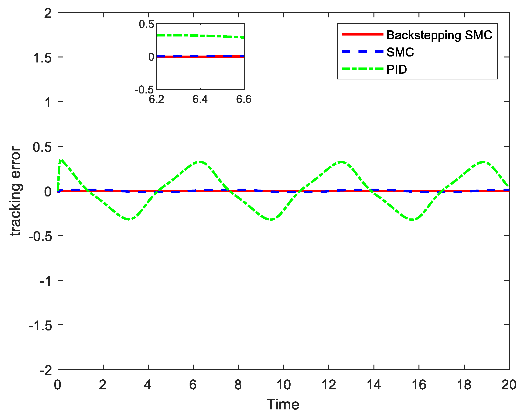
Figure 3.
Comparison of the tracking error of the three controllers.
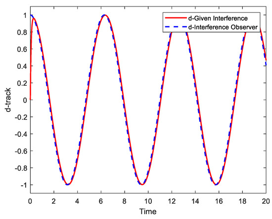
Figure 4.
Mismatched perturbation observer.
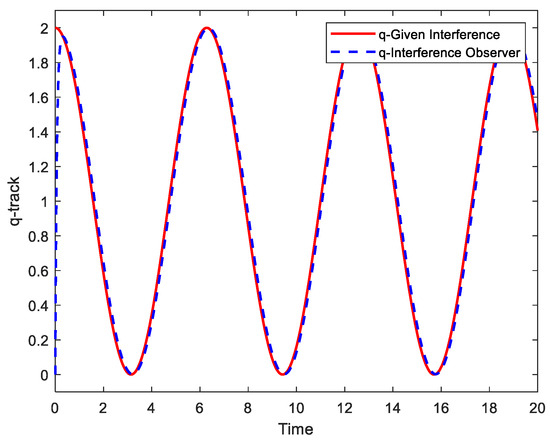
Figure 5.
Matching perturbation observer.
In order to compare the effect of the three different controllers on the system performance more intuitively, this paper uses the root mean square error (RMSE) for comparison. RMSE is a commonly used metric for measuring the accuracy of a prediction model or system, which is calculated as the root mean square of the difference between the predicted value and the true value, and the lower the value of RMSE, the better the performance of the system. We calculated the root mean square error of the system for each of the three controllers, as shown in Table 2. The RMSE value of the PID controller is 0.309403, the RMSE value of the sliding mode controller is 0.070866, and the RMSE value of the backstepping sliding mode controller designed in this paper is 0.002849, which is much smaller than those of the other two controllers.
Table 2.
RMSE data for the three controllers.
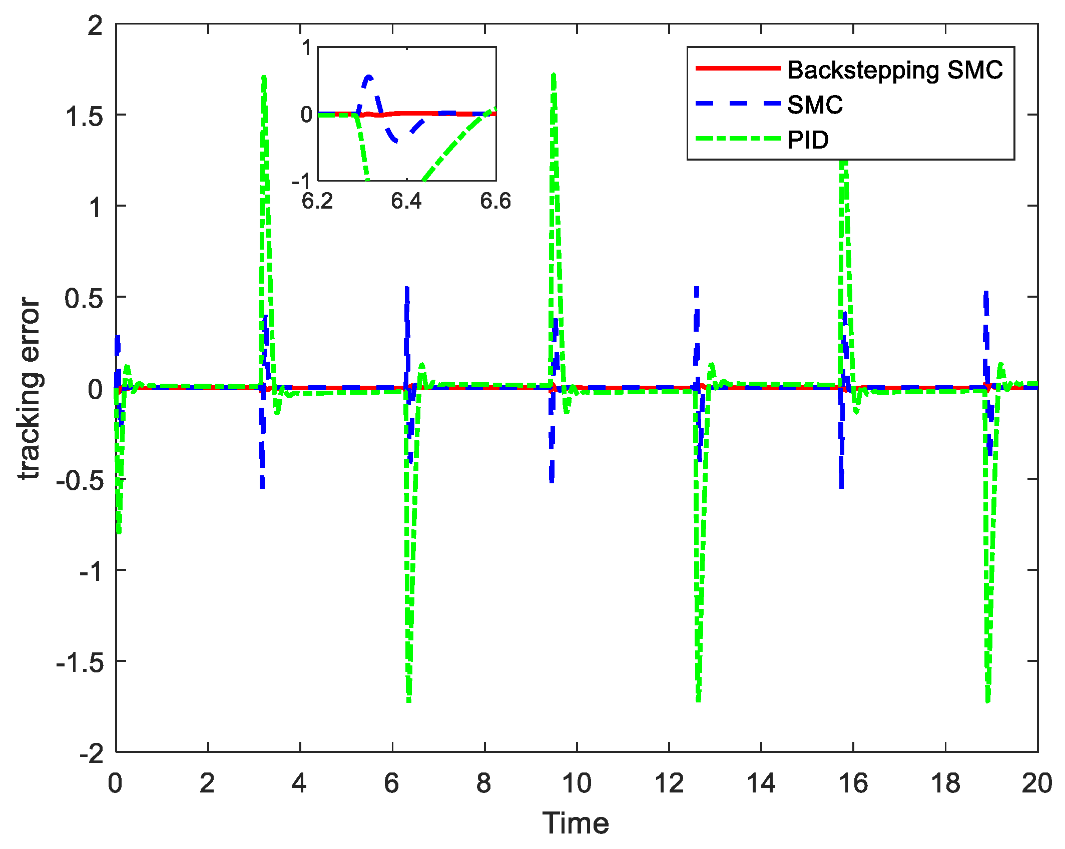
Experiment 2: Since it is difficult to track rapid changes in square waves, in order to verify the tracking of the control algorithm under different control target signals, the control target signal is changed to a square wave. The square wave signal, with an amplitude of 1 and a frequency of 1, is selected as the control target. The tracking performance of the above three controllers under the same conditions is shown in Figure 6, and the tracking error curve is shown in Figure 7.
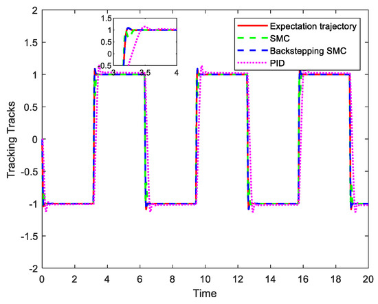
Figure 6.
Comparison of tracking effect of square wave signal.
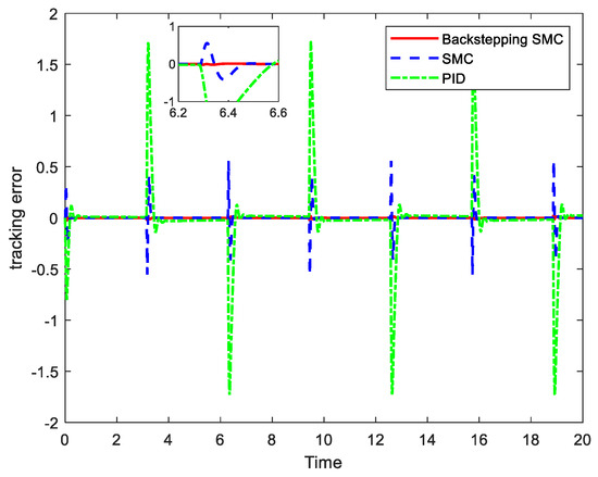
Figure 7.
Comparison of tracking error of square wave signal.
By conducting experiments with two different control signals and interference frequencies, as shown in Figure 2 and Figure 3, it is clear that the interference-observer-based backstepping sliding mode controller has better tracking performance. Compared with the common sliding mode controller, which has an initial maximum tracking error of −0.015∼+0.015 rad, the interference-observer-based inverse step sliding mode controller has an initial maximum tracking error of 0.011∼+0.011 rad and can converge to the desired curve in a short time of 0.5 s, and the error is stable at −0.001∼+0.001 rad. Similarly, in the case of harder-to-track square wave signals, the error of the common sliding mode controller produces a significant increase, while the controller proposed in this paper can still ensure good tracking performance.
The triggering instant and triggering interval of the event trigger are shown in Figure 8. From the figure, it can be observed that the event trigger triggers the data transmission only when the system state reaches the preset triggering conditions, and this mechanism contrasts with the traditional time-triggering method. By analysing the distribution characteristics of the triggering time interval, it can be seen that the event trigger mechanism can effectively filter redundant data and reduce unnecessary information transmission. Specifically, when the system state changes slowly, the triggering interval increases significantly; meanwhile, in the phase of a rapid state change, the triggering frequency increases accordingly. This adaptive feature significantly improves the bandwidth utilisation of the network system. At the same time, due to the reduction in redundant data transmission, the real-time performance and reliability of the system are also improved accordingly, providing an efficient data transmission solution for resource-constrained network environments.
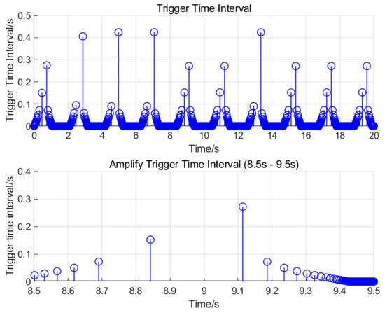
Figure 8.
Trigger instant and trigger interval of event trigger.
5. Conclusions
In this paper, a class of network-based hydraulic servo systems with high-precision tracking control problems is investigated, and a backstepping sliding mode control strategy based on event triggering and a disturbance observer is proposed. Considering the matching and mismatching disturbances that the system may be subject to, the accurate observation of the state and disturbances of the electro-hydraulic servo system is improved by designing a disturbance observer, and based on the observation, the corresponding backstepping sliding mode controller is designed to ensure the robustness of the system and its immunity to disturbances. At the same time, the demonstration of the stability of the system is accomplished. The effectiveness of the proposed method is verified by comparative simulation analysis. Future work can further optimise the parameter selection, expand to more complex systems, and verify the method’s applicability in a wider range of industrial scenarios.
Author Contributions
Writing—original draft, L.Y.; Writing—review & editing, L.Y. and X.S. All authors have read and agreed to the published version of the manuscript.
Funding
This research received no external funding.
Data Availability Statement
The original contributions presented in this study are included in the article. Further inquiries can be directed to the corresponding author.
Conflicts of Interest
The authors declare no conflict of interest.
References
- Li, Y.; Ai, C.; Yan, G.; Zhang, T.; Chen, G.; Jia, C.; Chen, W. Theoretical study on flexible transmission ratio of electro-hydraulic servo pump control system. Hydraul. Pneum. 2021, 45, 10–17. [Google Scholar]
- Zhang, D.; Shi, P.; Wang, Q.G.; Yu, L. Analysis and synthesis of networked control systems: A survey of recent advances and challenges. ISA Trans. 2017, 66, 376–392. [Google Scholar] [CrossRef] [PubMed]
- Deng, W.X.; Yao, J.Y. Extended-state-observer-based adaptive control of electrohydraulic servomechanisms without velocity measurement. IEEE/ASME Trans. Mechatron. 2020, 25, 1151–1161. [Google Scholar] [CrossRef]
- Wang, D.; Wang, Z.; Wang, Z.; Wang, W. Design of hybrid event-triggered containment controllers for homogeneous and heterogeneous multiagent systems. IEEE Trans. Cybern. 2020, 51, 4885–4896. [Google Scholar] [CrossRef] [PubMed]
- Wang, B.; Peng, W.; Zhang, R.; Ujjal, M.; Hu, X. Event-triggered differential-free control of hybrid energy storage system for electric vehicles. J. Mech. Eng. 2021, 57, 77–86. Available online: http://www.cjmenet.com.cn/CN/10.3901/JME.2021.14.077 (accessed on 20 April 2025).
- Yin, J.; Liu, B.; Chen, J. Double-Channel Time-Delay Network Predictive Control Based on Dynamic Event-Triggered Mechanism. J. Wuhan Univ. Sci. Technol. 2023, 46, 136–144. [Google Scholar]
- Gu, J.; Zhou, F.; Zhang, Y. Resilient Event-Driven Control of a Class of Nonlinear Networked Control Systems under DoS Attacks. J. Shenyang Inst. Eng. (Nat. Sci. Ed.) 2024, 20, 88–96. [Google Scholar]
- Shen, W.; Cui, X. Modelling and characterization of position servo system for pump-controlled cylinder. Hydraul. Pneum. Seal 2022, 42, 9. [Google Scholar] [CrossRef]
- Sun, X.; Wang, Y.; Cai, Y.; Wong, P.K.; Chen, L. An Adaptive Nonsingular Fast Terminal Sliding Mode Control for Yaw Stability Control of Bus Based on STI Tire Model. Chin. J. Mech. Eng. 2021, 34, 79. [Google Scholar] [CrossRef]
- Shen, W.; Wang, J. A robust controller design for networked hydraulic pressure control system based on CPR. Peer-Peer Netw. Appl. 2019, 12, 1651–1661. [Google Scholar] [CrossRef]
- Kim, S.; Choi, O.K.; Lee, D.H. Predictive DTC-PWM of PMSM based on zero voltage and 12 voltage vectors. J. Power Electron. 2020, 20, 1467–1477. [Google Scholar] [CrossRef]
- Hou, Q.; Ding, S.; Yu, X. Composite super-twisting sliding mode control design for PMSM speed regulation problem based on a novel disturbance observer. IEEE Trans. Energy Convers. 2020, 36, 2591–2599. [Google Scholar] [CrossRef]
- Jing, C.; Xu, H.; Jiang, J. Dynamic surface disturbance rejection control for electro-hydraulic load simulator. Mech. Syst. Signal Process. 2019, 134, 106293. [Google Scholar] [CrossRef]
- Yu, B.; Yao, J.; Zhu, Q.; Zhang, J.; Huang, Z.; Jin, Z.; Wang, X. Design, mathematical modeling and force control for electro-hydraulic servo system with pump-valve compound drive. IEEE Access 2020, 8, 171988–172005. [Google Scholar] [CrossRef]
- Li, Z.; Wang, C.; Quan, L.; Hao, Y.; Ge, L.; Xia, L. Study on energy efficiency characteristics of the heavy-duty manipulator driven by electro-hydraulic hybrid active-passive system. Autom. Constr. 2021, 125, 103646. [Google Scholar] [CrossRef]
- Yao, J.; Wang, P.; Dong, Z.; Jiang, D.; Sha, T. A novel architecture of electro-hydrostatic actuator with digital distribution. Chin. J. Aeronaut. 2021, 34, 224–238. [Google Scholar] [CrossRef]
- Shen, W.; Yuan, X.; Liu, M. Research on the control of hydraulic position tracking system based on event triggering and extended state observer. J. Mech. Eng. 2022, 58, 274–284. [Google Scholar] [CrossRef]


Disclaimer/Publisher’s Note: The statements, opinions and data contained in all publications are solely those of the individual author(s) and contributor(s) and not of MDPI and/or the editor(s). MDPI and/or the editor(s) disclaim responsibility for any injury to people or property resulting from any ideas, methods, instructions or products referred to in the content. |
© 2025 by the authors. Licensee MDPI, Basel, Switzerland. This article is an open access article distributed under the terms and conditions of the Creative Commons Attribution (CC BY) license (https://creativecommons.org/licenses/by/4.0/).