Article

Micro-Pore Structure and Fractal Characteristics of Shale Reservoir in Jiyang Depression

1
Petroleum Engineering Technology Research Institute of Shengli Oilfield, SINOPEC, Dongying 257067, China
2
Postdoctoral Scientific Research Working Station of Shengli Oilfield, SINOPEC, Dongying 257067, China
3
School of Petroleum Engineering, China University of Petroleum (East China), Qingdao 266580, China
*
Author to whom correspondence should be addressed.
Processes 2025, 13(6), 1704; https://doi.org/10.3390/pr13061704
Submission received: 12 April 2025 / Revised: 23 May 2025 / Accepted: 26 May 2025 / Published: 29 May 2025
(This article belongs to the Special Issue Advances in Unconventional Reservoir Development and CO2 Storage)

Abstract

In order to better understand the micropore structure of shale reservoir in Jiyang Depression, permeability damage test, low temperature nitrogen adsorption and scanning electron microscopy (SEM) were carried out on six cores in the target block. The adsorption isotherms were analyzed by Frenkel–Halsey–Hill (FHH) model, and the fractal dimensions of different layers were calculated. The results show that the shale pore system is mainly composed of organic nanopores, inorganic nanopores and micro-fractures. The inorganic pores are mainly distributed around or inside the mineral particles, while microcracks are commonly found between mineral particles or at the organic–mineral interface. Organic pores are located within or between organic particles. The results of nitrogen adsorption show that the shale pores are mainly H2/H3 hysteresis loops with wedge, plate or ink bottle shapes. The pore structure is highly complex, and the fractal dimension is high. The mean D1 fractal dimension, which represents pore surface roughness, is 2.3788, and the mean D2 fractal dimension, which represents pore structure complexity, is 2.7189. The fractal dimension is positively correlated with specific surface area and total pore volume and negatively correlated with average pore radius. The permeability damage rates of the N layer, B layer, and F layer are 17.39%, 20.2%, and 21.6%, respectively. The contact Angle of the core decreases with the increase in water skiing time. In this study, the micropore structure of different formations in Jiyang Depression is compared and analyzed, which provides valuable insights for the optimization and differentiated development of shale oil and gas resources.

1. Introduction

In recent years, with the rapid advancement in the exploration and development of unconventional oil and gas resources, increasing attention has been directed toward the pore structure of shale reservoirs [1,2,3]. Shale reservoirs are characterized by strong heterogeneity and are primarily dominated by nanoscale pores, exhibiting a highly complex and diverse pore system [4,5]. Traditional Euclidean geometry is inadequate for describing the irregular and intricate features of shale pore networks, which has led to the adoption of fractal geometry as a powerful tool for quantifying and characterizing the complexity of shale micro-pore systems.
Currently, two main categories of techniques are employed to investigate the microstructure of shale pores: fluid-assisted methods and image-based analytical methods. Fluid-assisted techniques include low-temperature nitrogen (N2) adsorption, carbon dioxide (CO2) adsorption, and high-pressure mercury intrusion. These methods provide valuable insights into shale pore characteristics but are limited by certain constraints. For instance, gas adsorption experiments have restricted pore-size detection ranges [6,7,8], while high-pressure mercury intrusion, though useful for assessing pore volume and distribution, may damage the rock matrix due to the low mercury saturation of micropores in shale, leading to incomplete or inaccurate characterization.
On the other hand, image-based methods, such as scanning electron microscopy (SEM) and focused ion beam scanning electron microscopy (FIB-SEM), provide direct visualization of pore morphology. While scattering imaging can capture pore geometry, its resolution limits the ability to delineate the fine-scale complexity of shale pores [9,10]. SEM, although capable of providing nanoscale resolution, still lacks the capability to perform comprehensive quantitative analyses across the entire pore network [11,12]. As a result, no single technique can fully capture the multifaceted nature of shale’s multiscale pore architecture.
In the domain of image-based analysis, several research teams have explored the effects of organic matter and mineral composition on shale pore development. For example, the use of low-pressure nitrogen adsorption (LP-N2A) and FIB-SEM imaging has been effective in characterizing various pore types, including organic pores, intergranular pores, intragranular pores, and microfractures. To enhance the efficiency and accuracy of image interpretation, advanced techniques such as attention-gate (AG) neural network models have been employed. These models focus on automatically segmenting target pore structures of different shapes and scales, improving the overall precision of image analysis [13,14,15].
In fluid-assisted characterization methods, nitrogen adsorption experiments have been extensively used to investigate shale micropore structures. Studies have shown that micropores and mesopores contribute significantly to the specific surface area and gas adsorption capacity of shale. Additionally, log–log curve fitting techniques have been applied to describe the fractal features of shale pores, correlating these parameters with fractal dimensions and other structural characteristics. Nitrogen adsorption isotherms have been analyzed to assess the influence of the physical and chemical properties of adsorbents on nitrogen adsorption behavior, while other research has focused on the relationships between surface area, pore volume, and pore morphology [16,17].
Other studies have investigated the factors influencing shale pore structure under different thermal treatment conditions. By applying the Frenkel–Halsey–Hill (FHH) model, researchers have calculated the fractal dimensions of shale pore systems and examined correlations between fractal dimensions, total organic carbon (TOC) content, and BET surface area [18,19]. Additionally, fractal theory has been used to derive models for predicting shale permeability. For instance, fractal dimensions obtained through the box-counting method and analytical solutions based on the Sierpinski carpet model have been employed to estimate shale permeability at various image resolutions [20,21].
Moreover, fractal analysis has been applied to tight sandstones, revealing that the fractal curves exhibit self-similarity, indicating that tight reservoirs possess complex pore throat structures and strong heterogeneity [22,23]. While previous studies have focused on the fractal dimension of shale pore structure, limitations have been identified in characterizing shale solely based on this parameter. Researchers have demonstrated that shale samples exhibit fractal properties within their pore structures under varying experimental conditions. Building on these findings, fractal theory has been extended to methods such as the box-counting method, the FHH model, and the Brooks–Corey model, which together provide a more comprehensive understanding of shale pore structure development [24,25,26].
In summary, while existing techniques have provided valuable insights into shale pore characteristics, the complexity and diversity of shale pore structures make it difficult to fully characterize them using a single method [27,28,29,30]. Future research needs to focus on the complementary nature of these techniques, particularly by integrating fluid-assisted methods with image-based analysis to improve the precision and efficiency of pore structure characterization. Furthermore, the continued application and refinement of fractal theory will offer deeper theoretical support for the quantitative analysis of shale pore systems.
However, most of the existing studies focus on the relationship between fractal dimension and the pore structure of general micro-reservoirs. There are still limitations in clarifying the spatial distribution patterns of different microscopic pore types, and there is a lack of reliable techniques for quantitatively characterizing their respective distributions. In this study, six shale core samples were collected in three blocks of the Jiyang Depression. Four experiments were carried out, namely scanning electron microscopy (SEM), nitrogen adsorption, permeability damage assessment and wetting Angle test. The scanning electron microscope image segmentation technology was established to accurately identify the pore morphology of shale and classify the pore types (organic pores, inorganic pores and micro-fractures). In addition, the relationship between the fractal dimension and the pore specific surface area and pore size distribution was determined based on the results of the nitrogen adsorption test. To clarify the occurrence behavior of fluids in the core, the permeability damage of the reservoir was evaluated and clarified through the fracturing fluid damage experiment. The research purpose of this paper is to describe the relationship between fractal dimension and pore structure, and at the same time characterize the influence degree of fracturing fluid on the physical properties of different shale reservoirs. Comprehensive analysis provides a solid theoretical basis for the implementation of the differentiated development strategy of shale reservoirs in the Jiyang Depression.

2. Experimental Method and Procedure

2.1. Experimental Materials

To clarify the differences in the physical properties of shale reservoirs in different blocks, six core samples were collected, respectively, in the three blocks of Bonan, Boxing, and Niuzhuang in the Jiyang Depression (China, Hereinafter referred to as B, F, N). The specific core data are shown in Table 1 and Table 2. The crude oil used is a mixture of Jiyang Depression crude oil (Shengli oil field, Dongying, China) and kerosene (Macklin Technology Co. Ltd., Qingdao, China), with a mixing ratio of 2:1. The experimental setup is composed of Newman MacroMR12-110H-I nuclear magnetic resonance spectrometer, rheometer, polymer vacuum pump, hand pump, intermediate container, capillary flowmeter, measuring cylinder, gas cylinder, and other supporting equipment.

2.2. Experimental Procedures

2.2.1. Nitrogen Adsorption Test

The nitrogen adsorption test is commonly used to analyze the porosity and surface area of materials, particularly in shale reservoirs, by examining the adsorption of nitrogen gas at low temperatures. This method is crucial for determining the specific surface area, pore volume, and pore size distribution of shale samples. The ability to measure these parameters is essential for understanding fluid storage and transport properties in shale formations. The specific experimental steps are as follows.
(1) Sample pretreatment: dry the shale sample in a vacuum drying oven at 60–110 °C for 12 h to remove water. After drying, the samples are cooled at room temperature and weighed with a precision balance. (2) Sample loading and preparation: put the pre-treated sample into the sample pool of the nitrogen adsorption instrument. Check instruments and liquid nitrogen systems to make sure lines are properly sealed. (3) Nitrogen adsorption experiment: start the instrument, vacuum the sample pool, reduce the temperature to 77 K, gradually increase the pressure with nitrogen, and record the adsorption amount and pressure data.

2.2.2. Scanning Electron Microscope Experiment

The purpose of the scanning electron microscopy (SEM) experiment is to observe and analyze the microstructure characteristics of shale samples through high-resolution electron microscopy technology, including their mineral composition, pore structure, particle size distribution, surface morphology, etc. By conducting detailed surface scans of the samples to obtain detailed images of the samples, the physical properties, chemical composition, and changes in shale under different environmental conditions can be studied.
(1) First, the shale samples need to be cut to the appropriate size and sanded smooth with sandpaper. (2) Subsequently, ultrasonic cleaning is used to remove surface impurities. Put the sample in the oven and dry it for 24 h. (3) Then, the shale flakes are adhered to an iron mold and placed in an argon ion polishing instrument. The surface of the shale was bombarded with an argon ion beam to make it smooth. Finally, the polished samples were fixed on the stage with conductive adhesive tape and treated with gold spraying. (4) Start the scanning electron microscope and gradually scan the surface of the sample to obtain images

2.2.3. Fracturing Fluid Damage Experiments

Fracturing fluid damage experiments are designed to simulate the effects of hydraulic fracturing fluids on shale cores, particularly to assess how such fluids influence core permeability. This method is important for understanding the long-term impact of fracturing fluids on reservoir productivity and the potential for damage to the pore structure. The specific experimental steps are as follows:
(1) After cleaning the core oil thoroughly, wash it clean and dry it in an oven for 72 h (the oven temperature is set at 130 °C). (2) Saturated simulated oil at a pressure of 30 MPa for one week. Perform T2 spectral sampling of nuclear magnetic resonance. After washing the core oil, it was dried in an oven for 72 h (the oven temperature was set at 130 °C). (3) The core was removed after being pressurized with 30 MPa saturated fracturing fluid for 12 h. (4) The permeability of the core was measured and T2 spectrum sampling was conducted. (5) The core was removed after being pressurized with 30 MPa saturated fracturing fluid for 24, 36, 48, and 60 h, and step (4) was repeated.

2.2.4. Contact Angle Experiment

The wetting angle experiment is used to assess the wettability of shale surfaces, which is critical for understanding fluid behavior in the pores of shale formations. Wettability refers to the affinity of a fluid to adhere to the surface of a solid, in this case, shale. This property directly influences fluid flow, capillary pressure, and reservoir performance, particularly in unconventional oil and gas reservoirs. By measuring the contact angle between water droplets and the shale surface, we can determine whether the surface is hydrophilic (water-attracting) or hydrophobic (water-repellent), which affects the behavior of injected fluids such as fracturing fluids. The specific experimental steps are as follows:
(1) Cut the shale core, clean it, and dry it in the oven for 24 h (the oven temperature is set at 130 °C). (2) Put the core sheet into the container and vacuum for 12 h and press 30 MPa to saturate the simulated oil for 24 h. (3) After pressurizing 30 MPa saturated slippery water for 24 h, remove the core. (4) Place the core slice on the measuring platform of the measuring instrument, adjust the focal length and observe the image. Stop adjusting the camera when the image of the core slice boundary is clear. (5) Use a micro-syringe to absorb the slippery water and inject 10 μL of water on the core surface according to the scale. (6) Adjust the focal length of the camera again, so that the junction between the water drop and the core in the center of the screen is clearly visible, take photos, and measure the contact Angle. Repeat steps (3), (4), (5), and (6) for a total of four times to measure the change rule of contact Angle. The wetting Angle device is shown in Figure 1.

3. Results

3.1. Electron Microscope Scanning Experiment

(1) Inorganic pores: mineral peripheral or internal inorganic pores are formed, primarily consisting of pores within calcite particles, pyrite, and apatite mineral peripheries. Among these, carbonate minerals predominantly comprise calcite, with a small amount of ankerite identified through energy spectrum testing. The carbonate minerals exhibit the formation of inorganic pores, with a significant presence of intra-granular pores observed in calcite. These pores display an irregular arrangement and are predominantly dispersed. The pore size distribution is 0.04–0.33 μm, and the pore shape is triangular, angular, or rectangular. It is the main reservoir space of shale oil.
The dolomite is mostly elliptical, and a small part is an irregular square. A large number of intergranular pores are developed between the ankerite minerals. Such pores are mostly due to the mechanical properties of minerals in the process of mechanical compaction. Differences or mineral particles support each other and develop pores between particles. Most of the pores are banded, and a small part is square.
Intragranular pores refer to the pores located inside the inorganic mineral particles; it usually includes intergranular pores developed between clay minerals and pyrite crystals. Pyrite is mainly prismatic, the development of intergranular pores of clay minerals is concentrated, and the sorting is poor. The intergranular pores of pyrite are mainly developed in the pores around clay minerals and pyrite crystal groups. The maximum pore size is 0.39 μm. Microcracks extend from the weak cementation parts of the mineral periphery. Most of the pores of pyrite are long strips. Apatite also develops peripheral pores between clay minerals, and the maximum pore size can reach 0.67 μm.
Most of the pores around the inorganic pores are long strips; the intragranular pores and intergranular pores are triangular, angular or rectangular, most of which are dispersed, without directional arrangement, and the pore connectivity is poor. The development of inorganic pores is shown in Figure 2.
(2) Cracks: micro-cracks in shale play an important role in gas seepage, connecting micro-pores with macro-cracks, and connecting some intergranular pores and dissolution pores. The formation of micro-cracks primarily occurs between mineral particles, organic matter, or the interface between mineral particles and organic matter, resulting in a banded structure. The development of microcracks is shown in Figure 3.
(3) Organic pores: shale nanoscale pores are contained in organic matter particles, called organic matter pores. Organic matter nanopores are formed through the thermal maturation process of organic matter, wherein geological processes give rise to numerous micro-fractures and minuscule pores. Organic pores are mainly distributed within or among organic matter, and some organic pores are coated by clay minerals. Their structure and distribution are affected by clay minerals, and their shape is long and irregular. A significant quantity of pyrite is found in close proximity to certain organic substances, and the interconnection of organic matter particles occurs alongside clay minerals, resulting in the formation of pore networks. The lipophilicity of organic matter particles makes them an important storage space for oil and gas. The organic pore development is shown in Figure 4 and Figure 5.

3.2. Nitrogen Adsorption Experiment

The nitrogen adsorption experiment allows for quantitative characterization of shale’s specific surface area, total pore volume, and average pore size. The specific surface area of 2#, 6#, and 8# shale rock samples calculated by BET equation is 0.5038, 2.7513, and 2.3049 m2/g, respectively, with an average value of 1.853 m2/g. The total pore volume of shale rock samples calculated by DFT model is 2.73, 8.921, and 6.553 × 103 cm3/g, respectively, with an average value of 6.068 × 10⁻³ cm3/g. Finally, the average pore size of shale rock samples is calculated by BJH model theory, and the average pore size is 21.68, 12.97, and 11.37 nm, respectively. The average value is 15.34 nm.
Figure 6 shows the nitrogen adsorption and desorption curves of three sets of shale cores. According to the definition of the International Union of Theory and Applied Chemistry (IUPAC), the curve formed between the adsorption capacity and the relative pressure is called an isotherm. The examination of shale isotherms reveals that the adsorption and desorption curves of the three shale groups do not align, leading to the occurrence of adsorption hysteresis. A distinct loop of hysteresis emerges between the adsorption and desorption curves, indicating a classification as type IV isotherm. IUPAC classifies hysteresis loops by the characteristics of hysteresis loops. H1 type, H2 (a) type, H2 (b) type, H3 type, H4 type.
The adsorption curve characteristics of all samples are similar. When the relative pressure is small, that is, when the pressure is between 0 and 0.4, the adsorption curve changes slowly, and the curve shape is slightly concave downward, reflecting the existence of a certain number of micropores. The width of the hysteresis loop is small, the inflection point of the adsorption isotherm usually appears in the middle pressure section, that is, when the relative pressure is between 0.4 and 0.8, the change speed of the adsorption curve increases, the curve shape is slightly raised upward, and the adsorption capacity increases gradually. When the relative pressure falls within the range of 0.8–1, there is a significant increase in the adsorption curve, noticeable concave features are observed, and an expansion in hysteresis loop width can be seen. These observations suggest a transition from micropores to macropores in terms of pore size.
The H2 hysteresis loop exhibits a broad shape, indicating a slow change in the adsorption curve. In contrast, the desorption curve shows a rapid decrease at medium pressure and is significantly steeper than the adsorption curve. Moreover, the pore structure of this reaction demonstrates complexity. On the other hand, for the H3-type hysteresis loop, it appears narrow with nearly parallel adsorption and desorption curves. When it is close to the saturation pressure, the adsorption curve rises steeply. In the high pressure region, it can show adsorption saturation, reflecting the pores including flat slit structure and fracture structure. The hysteresis loops of samples 2#, 6#, and 8# are close to those of H2 type and H3 type, which are in the transition stage between the two, corresponding to ink bottle pore and flat plate slit pore (Figure 6).

3.3. Pore Size Distribution Characteristics

The pore size distribution interval and pore volume ratio of shale are studied. The pore volume ratio interval of 2# shale is mainly 18.7–49 nm and 50–100 nm. The pore volume change rate of rock samples shows multi-peak distribution, mainly distributed in 1–4 nm, 5–8 nm, and 15–25 nm. Among them, the pore volume in the range of 0–18.7 nm accounts for 26%, the pore volume in the range of 18.7–49 nm accounts for 28%, and the pore volume in the range of 50–100 nm accounts for 45%.
The proportion of various pores in 6# shale is mainly 0–18.7 nm. The change rate of core pore volume shows a single peak distribution, and the peak value of shale is concentrated between 0 and 30 nm. Among them, the pore volume in the range of 0–18.7 nm accounts for 52%, the pore volume in the range of 18.7–48 nm accounts for 24%, and the pore volume in the range of 48–100 nm accounts for 23%.
The proportion of various pores in 8# shale is mainly 0–18.8 nm. The change rate of core pore volume shows a single peak distribution, and the peak value of shale is concentrated between 10 and 25 nm. Among them, the pore volume in the range of 0–18.8 nm accounts for 62%, and the pore volume in the range of 18.8–48.8 nm accounts for 26%. The large pores of 8# shale are poorly developed, and the total pore volume in the range of 48.8–100 nm accounts for only 11% (Figure 7).

3.4. Rock Physical Property Evaluation Experiment

3.4.1. Permeability Damage Experiment

According to previous studies, the damage rate of seepage capacity is defined, and the evaluation standard of damage degree is set to evaluate reservoir damage. The permeability damage rate D n is derived, and the permeability damage rate is defined as the ratio of the difference in permeability before and after saturated slippery water to the dry core permeability [31].
  D n = K i K n K i × 100 %
As shown in Figure 8, the permeability curve of matrix core shows a continuous downward trend with the increase in slippery water saturation. With the increase in slippery water saturation, the retention of slippery water gradually increases, resulting in pore blockage, resulting in a decrease in permeability and a gradual increase in damage to the reservoir space of matrix core.
The damage degree of slippery water to N9 core is the least, the permeability damage rate is 17.39%, the damage degree of F13 core is moderate (20.2%), and the damage degree of B8 core is the largest (21.6%). The changes in permeability and permeability damage rate are shown in Figure 8.

3.4.2. Shale Permeability Damage Evaluation

In order to investigate the effect of fracturing fluid on permeability of different shale reservoirs, fracturing fluid damage experiments were carried out with cores from three blocks.
The T2 value of NMR can be divided into short relaxation (<1 ms), medium relaxation (1–10 ms), and long relaxation (>10 ms) according to the relaxation time. According to previous studies, it is generally believed that short relaxation time represents micro and small pores in the pore, medium relaxation time represents medium and large pores in the pore, and long relaxation time represents large pores and micro cracks in the pore. According to previous studies and the nuclear magnetic experiments in this paper, the pore types are divided into micropores (<0.1 ms), small pores (0.1–1 ms) and large pores (1–100 ms).
The T2 spectra of the three matrix cores are shown in Figure 9, and the T2 spectra are all bimodal. However, the right peak amplitude of the three cores is significantly smaller than the left peak amplitude. The relative content of N9, B8, and F13 cores relative to the pore throat scale reaches 83.67%, 87.98%, and 77.70%, respectively, after the first compression saturation, indicating that the reservoir space of shale cores is dominated by micropores.
With the increase in water saturation, the fluid in the tiny pores is gradually bound, including clay bound fluid and capillary bound fluid. Clay bound fluid is the polar water molecules that are captured and adsorbed on the surface of clay minerals through the action of intermolecular gravity and static electricity and forms a hydration film on the surface of clay minerals. Capillary-bound fluid is a fluid that has no capillary resistance because it is difficult to flow in the formation due to the displacement pressure difference.
In the process of slippery water saturation, fracturing fluid will gradually occupy the pore channels in the reservoir. In the early stage of saturation, fracturing fluid is distributed in both small and large pores. With the increase in water saturation, more and more reservoirs are retained in shale reservoirs, and the effective seepage channels are gradually reduced, and the seepage capacity is weakened, resulting in the reduction in permeability. In the late stage of saturation, the increase in nuclear magnetic T2 spectrum signal is small, indicating that the micropores are gradually blocked by slippery water. However, in the later stage of saturation, the degree of blockage of slippery water in macropores is low, and most of the slippery water is free mobile fluid, so the slippery water can continue to enter the macropores under the condition of high saturation.

3.4.3. Contact Angle Analysis

The core is pressurized by 30 MPa saturated oil for 24 h and then pressurized by 30 MPa saturated slippery water for 24 h, 48 h, 96 h, and 120 h. Slip water is dripped onto the core surface to observe the change in the contact Angle of slip water after different saturation time, as shown in Figure 10.
According to the experimental results, the contact Angle of F reservoir has the fastest decreasing trend, and the slippery water has the greatest ability to change its wettability. The decrease trend of reservoir wetting Angle of B is the slowest, which indicates that the reservoir physical property is less affected by slippery water intrusion.
Under the action of pressure saturation, the contact Angle of slippery water on the core surface decreases gradually, and the water wetness increases. With the increase in the concentration, the range of contact Angle changes first increases and then decreases. Generally speaking, capillary force can promote the imbibition process and is the imbibition driving force. However, when the wettability of the core is oil-wet, the capillary force will hinder the imbibition process, which is the imbibition resistance. The larger the contact Angle, the weaker the core moisture and the smaller the capillary force.
Therefore, it is necessary to choose the appropriate surfactant concentration comprehensively to avoid the decrease in imbibition effect due to the decrease in capillary force.

4. Discussion

4.1. Quantitative Evaluation of Pore Structure

Based on the electron microscope images obtained by scanning, image denoising, artifact removal, and uneven brightness adjustment were carried out to segment the pore structure and extract the pore structure features (Figure 11).
The characteristic parameters of pore structure obtained based on pore image include area, perimeter, equivalent diameter, aspect ratio, long and short axis length, and shape factor. The major axis is the maximum Ferret diameter, the short axis is the minimum Ferret diameter, the equivalent diameter is the diameter of the circle with the same area in two dimensions, and the perimeter is the circumference of Kulofton.
Equivalent diameter formula:
E q D = 4 × A r e a π
Girth formula:
C r o f t o n p e r i m e t e r = L X = 0 π D X , a d a
Factor formula:
D X , α = N α X d x ,   S h a p e A P = C r o f t o n P e r i m e t e r 2 4 π A r e a
Area formula:
A x = i , j g x i , y j  
g x i , y j = 1   i f   t h e   p i x e l   l i e s   w i t h i n   t h e   o b j e c t   X ,   g ( x i , y j ) = 0   o t h e r w i s e
Taking the extraction of pore characteristic parameters in calcite as an example, the law of pore structure parameters and equivalent diameter is analyzed (Figure 12).
The correlation between pore structure parameters and the equivalent diameter is significant, making it a suitable choice for assessing the growth of organic and inorganic pores. Research findings indicate notable variations in pore size distribution among different types of shale oil reservoirs.
Table 3 shows the pore size distribution characteristics of intergranular pores, intragranular pores, and organic matter pores. Intergranular voids refer to the formation of pores between particles as a result of variations in mineral properties or the interlocking support among mineral particles during mechanical compaction. Intragranular pores refer to the pores inside inorganic mineral particles, which usually include intergranular pores developed between clay minerals and pyrite crystals, as well as dissolution pores formed in some minerals. Organic pores are generally developed inside or at the edges of organic matter to form pores.

4.2. Calculation of Fractal Dimension

Based on the existing studies of predecessors, the formula of the fractal dimension theory of the FHH model is [32,33,34,35,36]
ln V = K ln ln P 0 P + C
K = D 3
where P 0 is the saturated steam pressure and P is the equilibrium pressure ( M P a ) ; V is the adsorption volume ( m 3 ) of nitrogen at pressure P , which can be equivalent to the pore volume, and D is the fractal dimension. K   and C are constants of this function.
Based on this theory, the data of nitrogen adsorption experiment are analyzed. Fractal dimension D can reflect the heterogeneity of pore structure, and its value is distributed between 2 and 3. When fractal dimension D   approaches 2, the development of shale pore structure is relatively simple, with strong homogeneity and good connectivity of pore structure [37,38,39,40]. When the fractal dimension D approaches 3, there is a high level of complexity and diversity in the internal development of the pore structure. The dispersion of pore size and throat is evident, indicating strong heterogeneity and disconnection within the pore structure. On the other hand, when the fractal dimension D exceeds 3 or falls below 2, it can be inferred that there are limited shape characteristics present in the pores, suggesting unavailability of suitable fractal conditions.
The adsorption curve of ln V and ln ln P 0 P to carry on the fitting, according to the previous formula, when P 0 / P   = 0.5, corresponding to the aperture size of 2 nm [41]. At the same time, it has been mentioned earlier that shale typically lacks significant pore development. The demarcation between high and low pressure regions is established at a relative pressure of 0.5, with the low-pressure region being defined at a relative pressure of ( 0 < P 0 / P < 0.5 ) and the high-pressure region at a relative pressure of ( 0.5 < P 0 / P < 1 ). This partitioning method is similar to that of AN et al., and the results show that the experimental trend is consistent. Consequently, an investigation into the fractal dimension of these distinct regions is conducted. The change in fractal dimension between apertures smaller than 2 nm and larger than 2 nm was determined [37,42,43,44,45].
The fractal dimension of the low-pressure division is designed as D1, the orange part in Figure 13; the fractal dimension of the high-pressure division is designed as D2, the blue part in Figure 13. Previous studies suggest that D1 mainly represents the characteristics of the pore surface and pore development. D2 mainly represents the pore structure characteristics and the development of mesopores. The larger D1 is, the more irregular the inner surface of the pore is and the worse the smoothness is. The larger D2 is, the more complex and dispersed the pore size distribution is, and the smaller the pore size is.
Based on Formulas (6) and (7), we calculated the fractal dimension D1 and the fractal dimension D2. After linear fitting, it can be known that all three shale samples conform to the fractal law. The fractal dimension distribution of the shale samples was determined to be between 2.2319 and 2.7669, with an average value of 2.5489. The fractal dimension D1 is distributed within the range of 2.2319 to 2.4574, and its average value is 2.3788. The fractal dimension D2 is distributed within the range of 2.6311–2.7696, and its average value is 2.7189 (Table 4). It can be found that the fractal dimension D2 of the same shale sample is greater than the fractal dimension D1, indicating that the pore structure development of larger pores (pore diameter greater than 2 nm) in the same rock sample is more complex and irregular. It can be known through the comparison of fractal dimensions that the development of internal pores in shale samples is more complex than that on the pore surface (Figure 13).

4.3. Relationship Between Fractal Dimension and Pore Structure Parameters

After fitting the fractal dimension D 1 and D 2 , it is found that the correlation of total pore volume, specific surface area, and average pore diameter is similar, and the correlation coefficient ( R 2 ) of them is more than 0.9, but the correlation of fractal dimension D 2 is stronger. It was found that the fractal dimension D 1 showed a weak positive correlation with the total pore volume and specific surface area, and a weak negative correlation with the average pore size [42,46,47]. This indicates that when the pore surface is well developed, the fractal dimension D 1 can characterize the complexity of the pore surface. The fractal dimension D 2 is positively correlated with the specific surface area and total pore volume, and negatively correlated with the average pore size, which can represent the development in the pore interior, indicating that the larger the specific surface area and pore volume, the more complex the pore interior structure.
The relationship between the fractal dimension and pore structure parameters of the shale in the Jiyang Depression is shown in Table 5, and the fitting curve is shown in Figure 14. Firstly, the specific surface area was significantly positively correlated with the total pore volume (R2 = 0.9605), indicating that the larger the specific surface area of the sample, the larger the total pore volume, indicating more abundant pore development. Secondly, there is a negative correlation between the average pore diameter and the total pore volume (R2 = 0.7414), that is, a larger pore diameter is often accompanied by a smaller pore volume, which may be related to a higher proportion of micropores in the pore volume.
In the fractal dimension analysis, the mean pore diameter is negatively correlated with the fractal dimension ( D 1 , D 2 ) (R2 > 0.94), which means that when the mean pore diameter increases, the structural complexity of the pore (reflected by the fractal dimension) decreases. There is a positive correlation between the fractal dimension ( D 1 and D 2 ) and the pore volume (R2 > 0.88), indicating that the pore structure complexity increases with the increase in pore volume.
Finally, there is a strong positive correlation between the specific surface area and the fractal dimension (R2 > 0.97), especially the D 2 dimension, indicating that the increase in specific surface area is accompanied by the increase in pore structure complexity. In summary, fractal dimension not only reflects the complexity of pore structure but is also closely related to the geometric characteristics of pores (such as specific surface area and pore size distribution, etc.), which is of great significance for understanding the microscopic pore characteristics and energy storage capacity of shale.

5. Conclusions

(1)
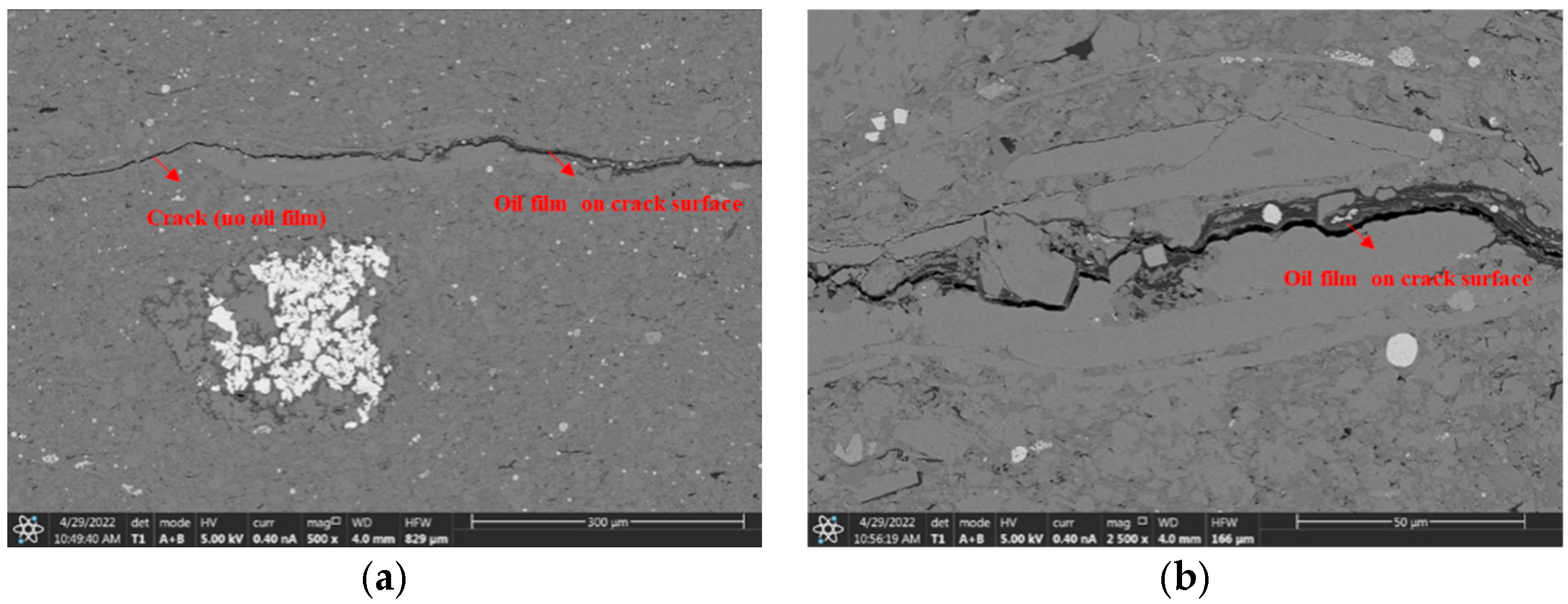
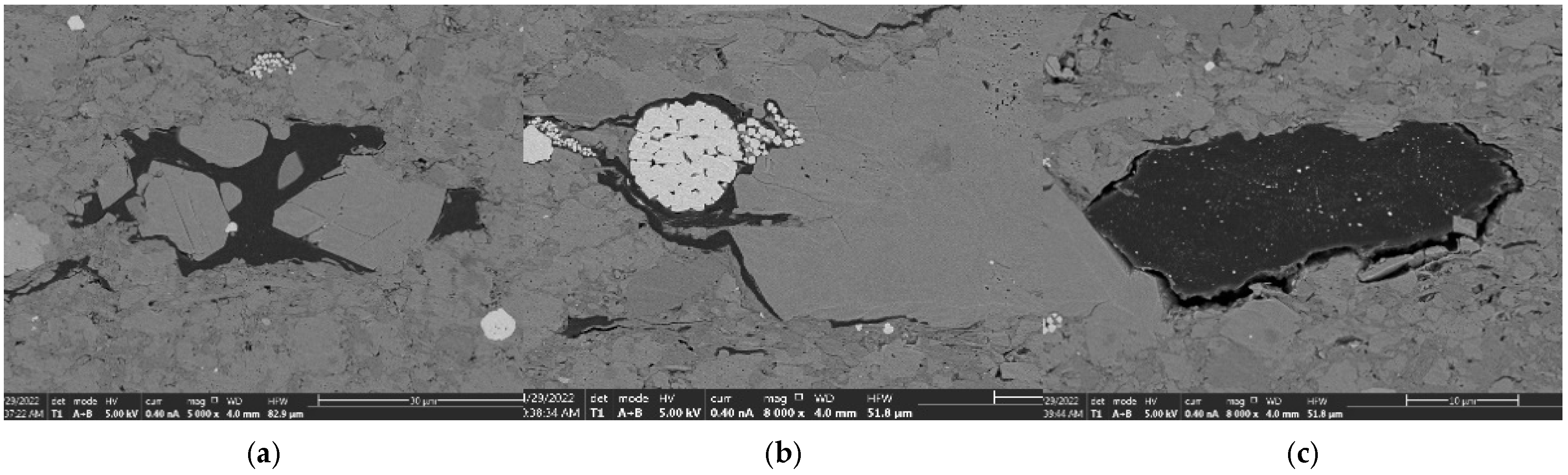
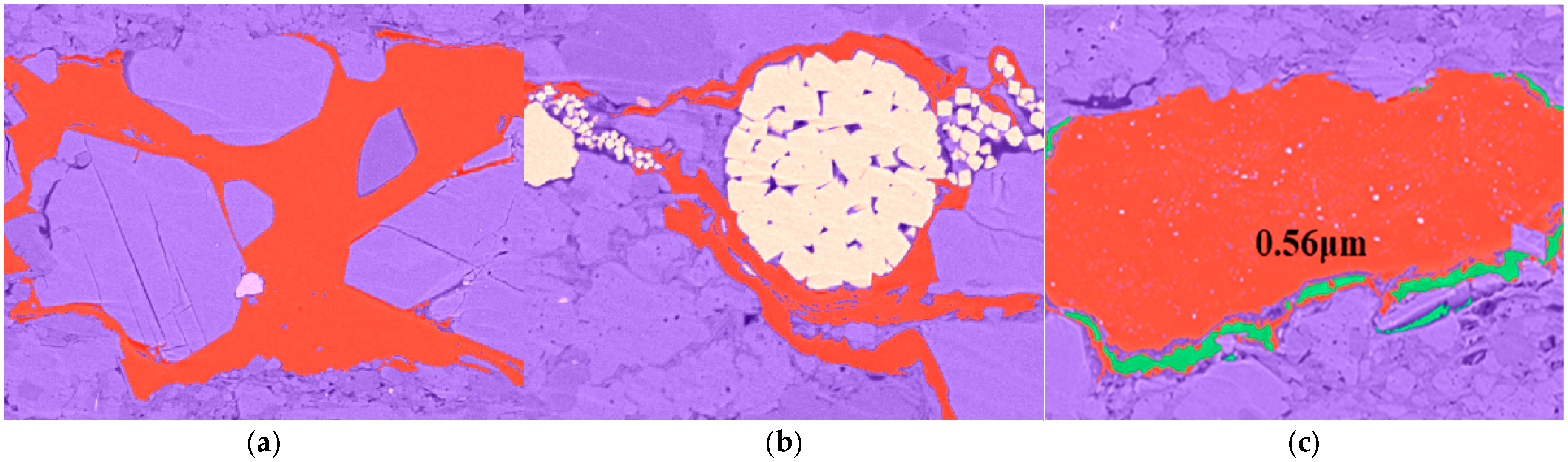
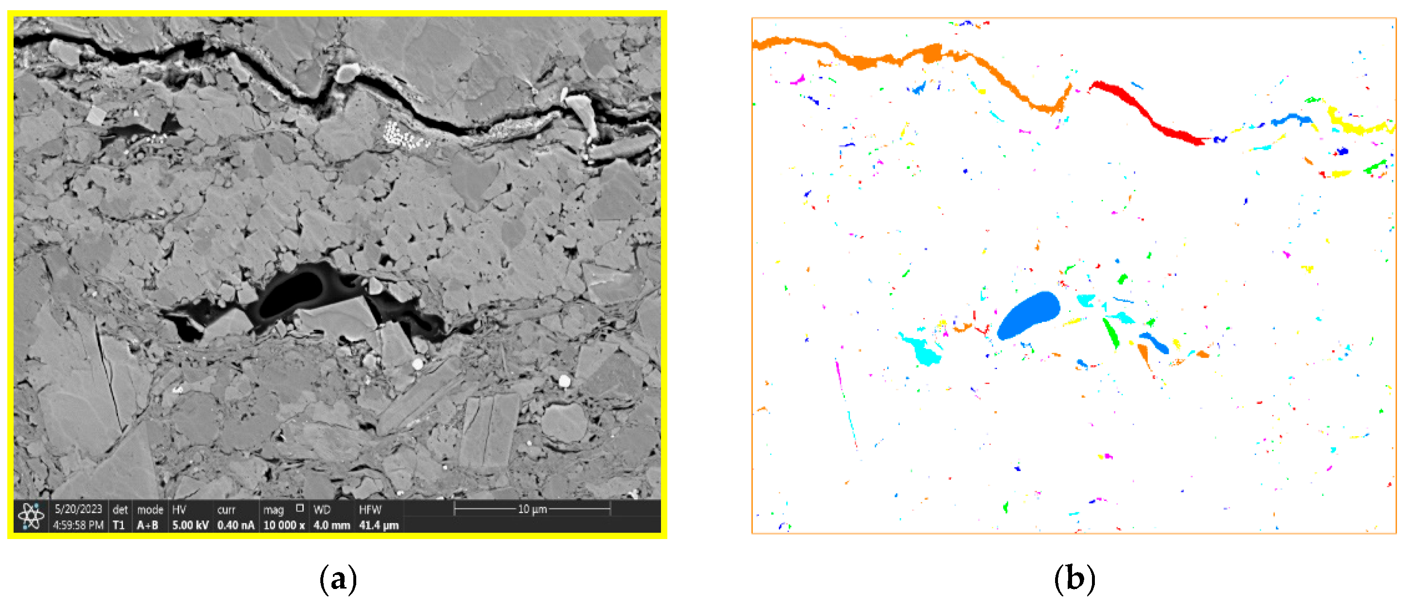
The dominant pore structure observed in the shale reservoirs of Jiyang Depression primarily consists of inorganic pores, with a lesser occurrence of micro-fractures and organic pores. Inorganic pores mainly include intergranular pores developed around minerals and intragranular pores developed inside minerals. Fractures are mainly developed between mineral particles or organic matter or between mineral particles and organic matter. The organic matter pores are mainly distributed in or between organic matter and are partially surrounded by clay minerals.
(2)
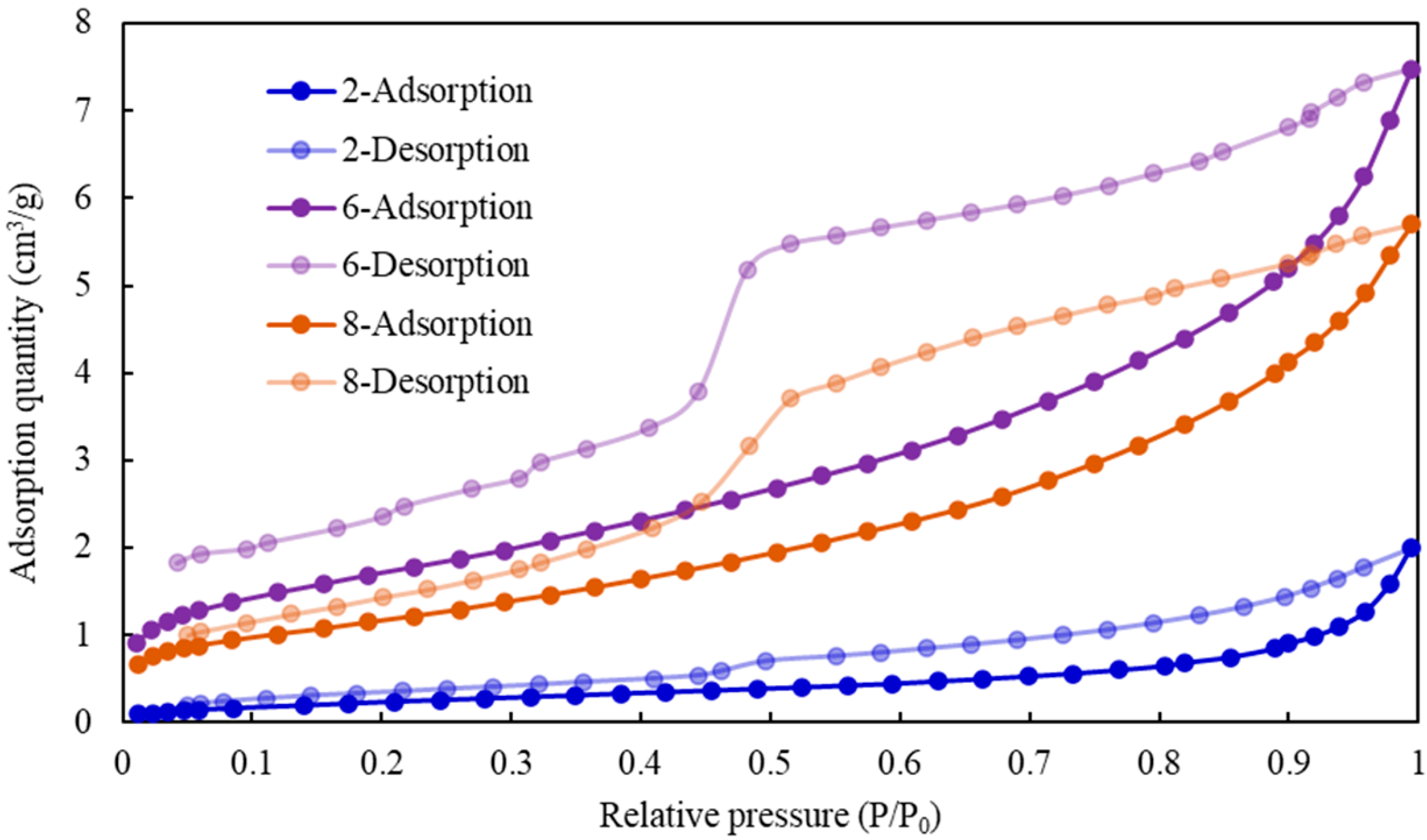
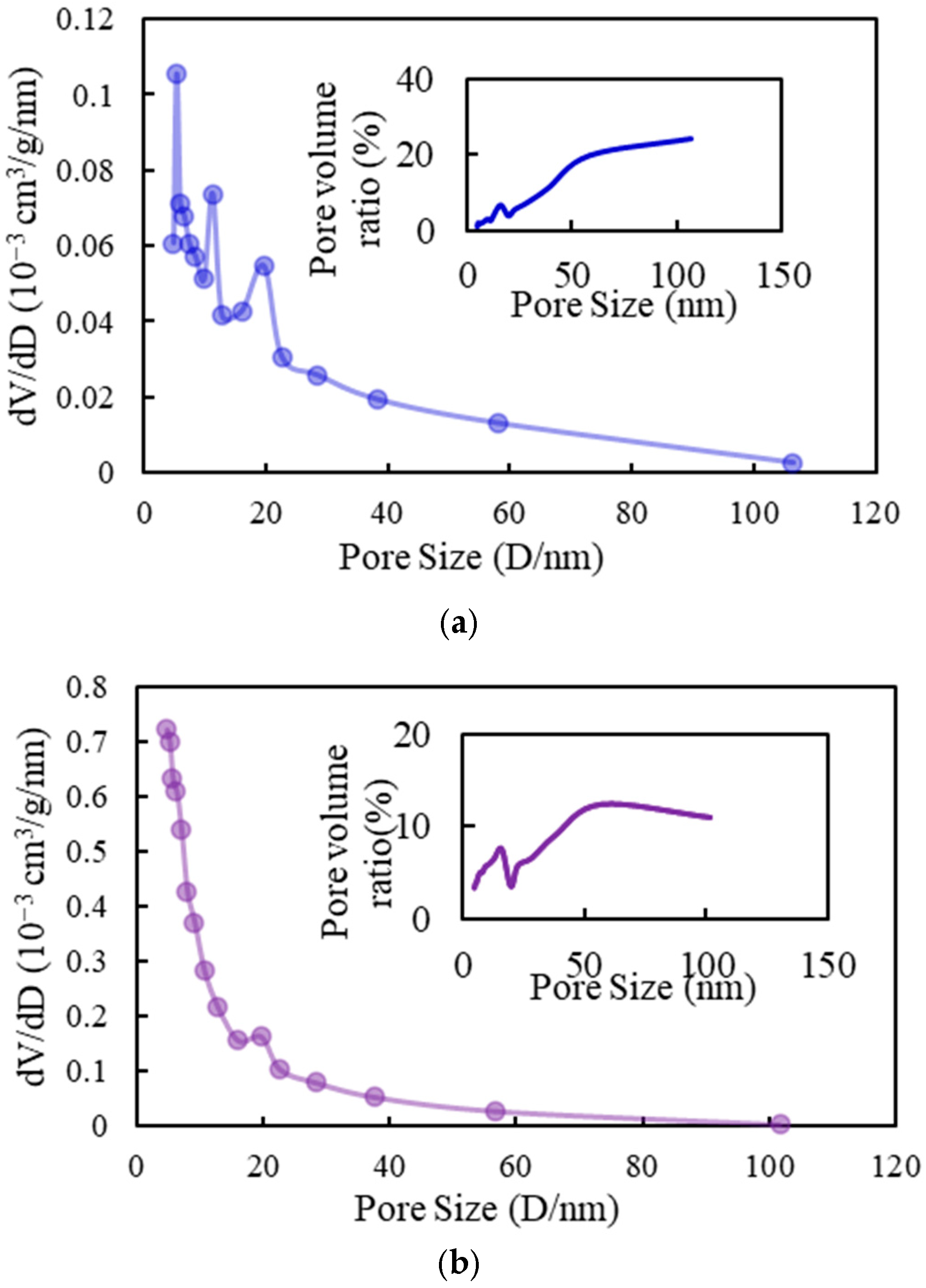
There is a strong correlation between the equivalent diameter of pores and the parameters describing their structure in shale reservoirs. The distribution of pore sizes varies significantly among different types of pore structures found in shale formations. A unimodal distribution of changes in pore volume indicates that medium and large pores dominate the composition of shale rock samples. Conversely, a scattered distribution with multiple peaks suggests that rock samples are distributed across various pore sizes.
(3)
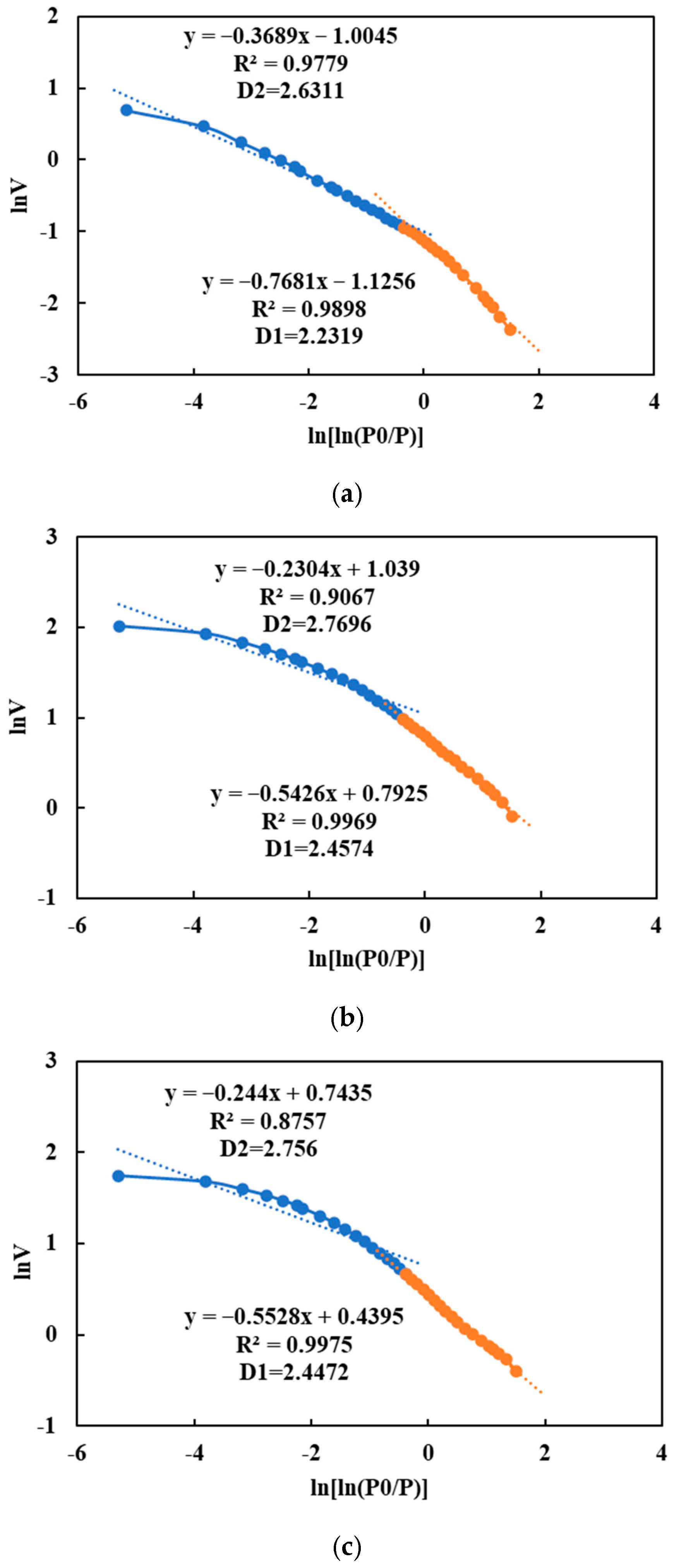
By utilizing the FHH model, we computed the fractal dimensions of various pore sizes using a relative pressure threshold of 0.5 to distinguish between regions with high and low pressures. The average value of the fractal dimension, which characterizes the surface properties and small pores, was determined D 1 to be 2.3788. Furthermore, we obtained an average fractal dimension D 2 of 2.7189 for medium-sized pores. A smaller deviation from a fractal dimension D 1 of 2 indicates enhanced homogeneity in pore surface characteristics and regularity in pore structure.
(4)
Both fractal dimension D 1 and fractal dimension D 2 are correlated with specific surface area, total pore volume, and average pore diameter. However, the correlation of fractal dimension D 2 is better, which can more intuitively characterize the development in the pore interior, indicating that when D 2 is closer to 3, the specific surface area and pore volume are larger, and the internal structure of the pore is more complex.
(5)
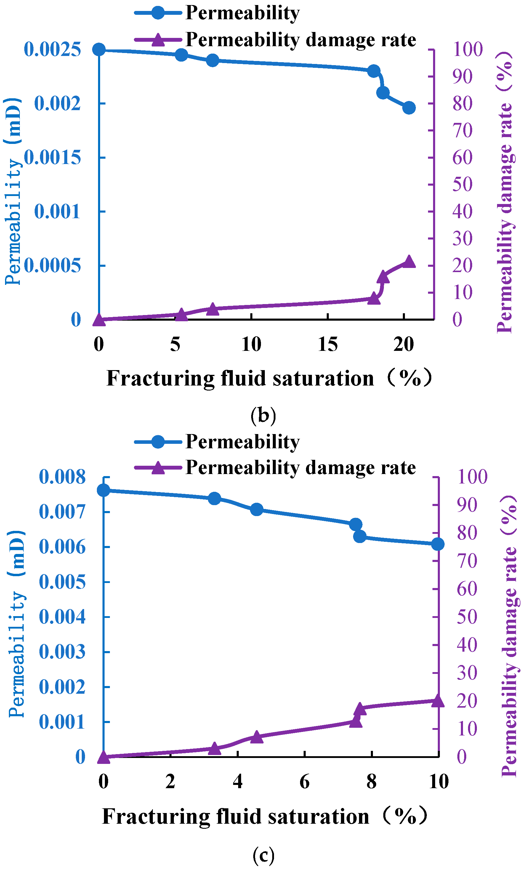
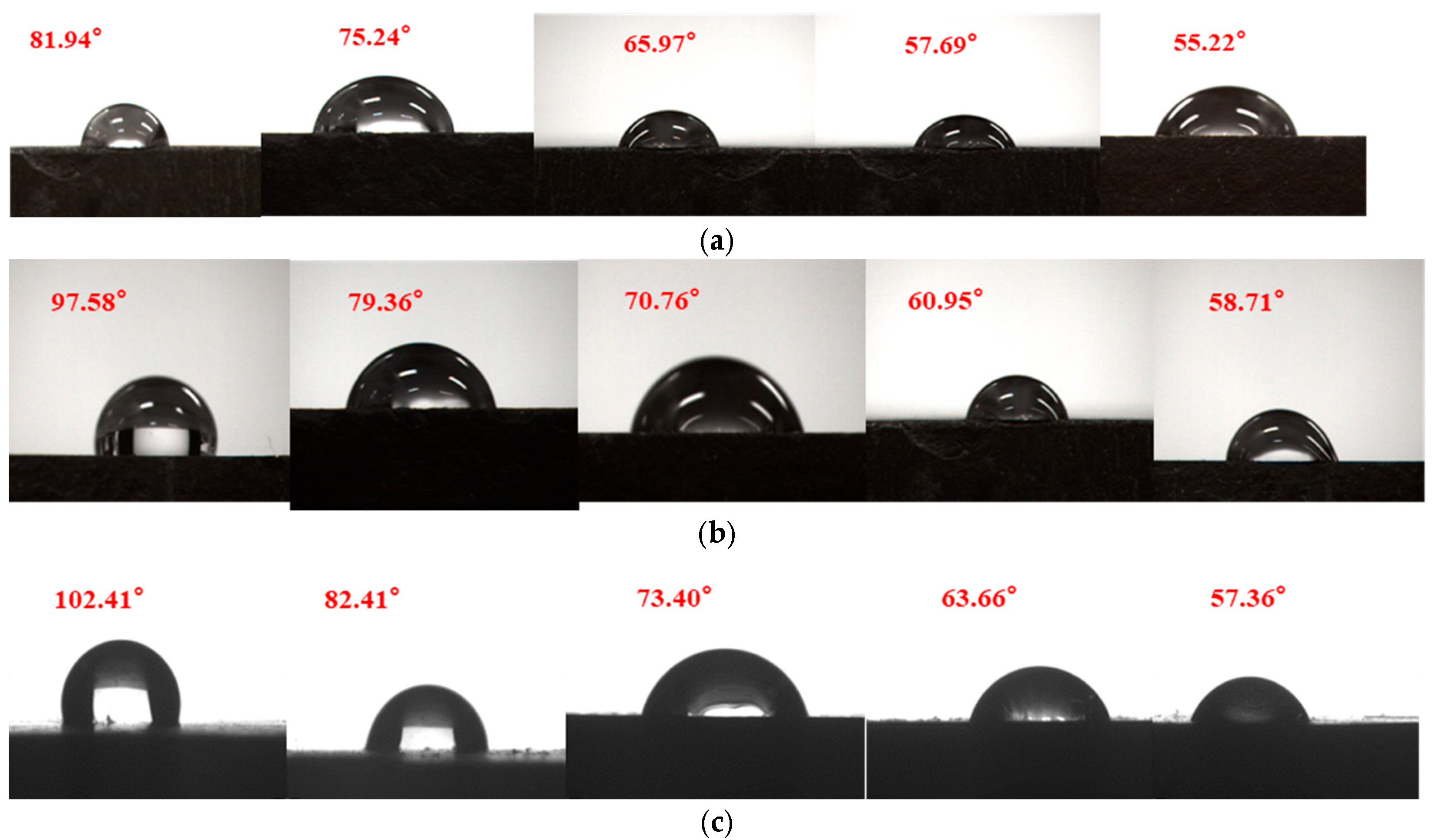
The permeability curve of the core continues to decline with the increase in the slippery water saturation; the contact Angle of cores in the three blocks of Y depression decreases with the increase in the action time of slippery water. After the slippery water enters the core, it erodes clay minerals, and the surface hydrophilicity gradually increases, while the wetting Angle gradually decreases.

Research Contributions and Future Directions

This study contributes significantly to understanding the pore structure of shale reservoirs in the Jiyang Depression, highlighting the importance of inorganic pores, micro-fractures, and organic pores. Additionally, the application of fractal geometry, particularly the FHH model, provides a deeper understanding of pore structure complexity, surface properties, and internal pore development. The observed correlations between fractal dimensions and pore characteristics underscore the utility of fractal analysis in describing the multi-scale nature of shale pore systems.
However, there are still several research gaps that need to be addressed. For instance, the impact of varying mineral compositions on pore structure and permeability remains underexplored. Future studies could focus on the influence of specific clay minerals and organic matter types on pore development and their effects on the overall permeability of the reservoir. Additionally, while the study successfully demonstrated the use of fractal dimensions to characterize pore structure, further research is needed to refine the relationship between fractal dimensions and other petrophysical properties, such as the pore throat size distribution and fluid flow characteristics.
Future research could also explore advanced imaging and simulation techniques to better understand the dynamic behavior of pore networks under varying pressure and saturation conditions. The development of more precise and robust models to predict reservoir performance based on pore structure analysis will be essential for enhancing the accuracy of unconventional resource evaluations.

Author Contributions

Conceptualization, Q.Q.; Methodology, M.L.; Validation, A.Z.; Investigation, F.Y.; Resources, Q.Q.; Data curation, Q.Q. and W.H.; Writing—original draft, L.L.; Writing—review and editing, W.H. All authors have read and agreed to the published version of the manuscript.

Funding

This paper was supported by China Postdoctoral Science Foundation (2021M702304), Shandong Provincial Natural Science Foundation (ZR2021QE260 and ZR2024ME037).

Data Availability Statement

The data presented in this study are available on request from the Shengli oilfield.

Conflicts of Interest

Authors Qin Qian, Mingjing Lu, Anhai Zhong, Feng Yang and Wenjun He were employed by SINOPEC. The remaining author declares that the research was conducted in the absence of any commercial or financial relationships that could be construed as a potential conflict of interest.

References

  1. Zou, C.; Zhu, R.; Wu, S.; Yang, Z.; Tao, S.; Yuan, X.; Hou, L.; Yang, H.; Xu, C.; Li, D.; et al. Types, characteristics, genesis and prospects of conventional and unconventional hydrocarbon accumulations:taking tight oil and tight gas in China as an instance. Acta Pet. Sin. 2012, 33, 173–187. [Google Scholar]
  2. Zou, C.N.; Zhang, G.S.; Yang, Z.; Tao, S.Z.; Hou, L.H.; Zhu, R.K.; Yuan, X.J.; Ran, Q.Q.; Li, D.H.; Wang, Z.P. Geological concepts, characteristics, resource potential and key techniques of unconventional hydrocarbon: On unconventional petroleum geology. Pet. Explor. Dev. 2013, 40, 385–399. [Google Scholar] [CrossRef]
  3. Wang, H.; Shi, Y.; Xu, D.; Chen, X.; Li, C. Unconventional reservoir pore structure characterization techniques and progress. Pet. Geol. Recovery 2019, 26, 21–30. [Google Scholar] [CrossRef]
  4. Yang, Z.; Zou, C.; Wu, S.; Lin, S.; Pan, S.; Niu, X.; Men, G.; Tang, Z.; Li, G.; Zhao, J.; et al. Formation, distribution and resource potential of the “sweet areas (sections)” of continental shale oil in China. Mar. Pet. Geol. 2019, 102, 48–60. [Google Scholar] [CrossRef]
  5. Brunauer, S.; Deming, L.S.; Deming, W.E.; Teller, E. On a theory of the van der waals adsorption of gases. J. Am. Chem. Soc. 1940, 62, 1723–1732. [Google Scholar] [CrossRef]
  6. Chen, K.; Liu, X.; Liu, J.; Zhang, C.; Guan, M.; Zhou, S. Lithofacies and pore characterization of continental shale in the second member of the Kongdian Formation in the Cangdong Sag, Bohai Basin, China. J. Pet. Sci. Eng. 2019, 177, 154–166. [Google Scholar] [CrossRef]
  7. Yu, L.; Lu, J. The Fundamental Principles and Applications of Scanning Electron Microscopy. Exp. Sci. Technol. 2019, 17, 85–93. [Google Scholar]
  8. Bao, F.; Yu, L.; Rui, X.; Zhang, Q.; Fan, M.; Ma, Z. Microstructure and SEM-Raman study of organic matter pore heterogeneity in shale. Pet. Geol. Exp. 2021, 43, 871–879. [Google Scholar]
  9. Zhang, W.K.; Shi, Z.J.; Tian, Y.M.; Xie, D.; Li, W.J. The combination of high-pressure mercury injection and rate-controlled mercury injection to characterize the pore-throat structure in tignt sandstone reservoirs. Fault-Block Oil Gas Field 2021, 28, 14–20. [Google Scholar]
  10. Li, T.; Jiang, Z.; Su, P.; Zhang, X.; Chen, W.; Wang, X.; Ning, C.; Wang, Z.; Xue, Z. Effect of laminae development on pore structure in the lower third member of the Shahejie Shale, Zhanhua Sag, Eastern China. Interpretation 2020, 8, T103–T114. [Google Scholar] [CrossRef]
  11. Pszonka, J.; Sala, D. Application of the mineral liberation analysis (MLA) for extraction of grain size and shape measurements in siliciclastic sedimentary rocks. E3S Web Conf. 2018, 66, 02002. [Google Scholar] [CrossRef]
  12. Pszonka, J.; Schulz, B. SEM Automated Mineralogy applied for the quantification of mineral and textural sorting in submarine sediment gravity flows. Gospod. Surowcami Miner.—Miner. Resour. Manag. 2022, 38, 105–131. [Google Scholar] [CrossRef]
  13. Huang, W.; Ma, X.; Zhou, X.; Liu, J.; He, T.; Tao, H.; Li, S.; Hao, L. Characteristics and controlling factors of pore structure of shale in the 7th member of Yanchang Formation in Huachi area, Ordos Basin, China. J. Nat. Gas Geosci. 2023, 8, 319–336. [Google Scholar] [CrossRef]
  14. Yasin, Q.; Liu, B.; Sun, M.; Sohail, G.M.; Ismail, A.; Majdanski, M.; Golsanami, N.; Ma, Y.; Fu, X. Automatic pore structure analysis in organic-rich shale using FIB-SEM and attention U-Net. Fuel 2024, 358, 130161. [Google Scholar] [CrossRef]
  15. Wang, G.; Chen, X.; Wang, G.; Zhang, H.; Wang, J.; Xu, H. Accurate structural characterization of nanopores in coal by cryo-FIB-SEM. Adv. Geo-Energy Res. 2024, 14, 187–200. [Google Scholar] [CrossRef]
  16. Ding, C.; He, J.; Wu, H.; Zhang, X. Nanometer Pore Structure Characterization of Taiyuan Formation Shale in the Lin-Xing Area Based on Nitrogen Adsorption Experiments. Minerals 2021, 11, 298. [Google Scholar] [CrossRef]
  17. He, H.; Liu, P.; Xu, L.; Hao, S.; Qiu, X.; Shan, C.; Zhou, Y. Pore structure representations based on nitrogen adsorption experiments and an FHH fractal model: Case study of the block Z shales in the Ordos Basin, China. J. Pet. Sci. Eng. 2021, 203, 108661. [Google Scholar] [CrossRef]
  18. Zapata, Y.L.; Sakhaee-Pour, A. Modeling adsorption–desorption hysteresis in shales: Acyclic pore model. Fuel 2016, 81, 557–565. [Google Scholar] [CrossRef]
  19. Wu, X.; Cai, M.; Zhu, Y.; Guo, Q.; Wang, P.; Dong, J. An experimental study on the fractal characteristics of the effective pore structure in granite by thermal treatment. Case Stud. Therm. Eng. 2023, 45, 102921. [Google Scholar] [CrossRef]
  20. Song, W.; Wang, D.; Yao, J.; Li, Y.; Sun, H.; Yang, Y.; Zhang, L. Multiscale image-based fractal characteristic of shale pore structure with implication to accurate prediction of gas permeability. Fuel 2019, 241, 522–532. [Google Scholar] [CrossRef]
  21. Sheng, G.; Su, Y.; Zhao, H.; Liu, J. A unified apparent porosity/permeability model of organic porous media: Coupling complex pore structure and multi-migration mechanism. Adv. Geo-Energy Res. 2020, 4, 115–125. [Google Scholar] [CrossRef]
  22. Li, K.; Kong, S.; Xia, P.; Wang, X. Microstructural characterisation of organic matter pores in coal-measure shale. Adv. Geo-Energy Res. 2020, 4, 372–391. [Google Scholar] [CrossRef]
  23. Mandelbrot, B.B. On the geometry of homogeneous turbulence with stress on the fractal dimension of the iso-surfaces of scalars. J. Fluid Mech. 1975, 72, 401–416. [Google Scholar] [CrossRef]
  24. Mandelbrot, B.B.; Passoja, D.E.; Paullay, A.J. Fractal character of fracture surfaces of metals. Nature 1984, 308, 721–722. [Google Scholar] [CrossRef]
  25. Hansen, J.P.; Skjeltorp, A.T. Fractal pore space and rock permeability implications. Phys. Rev. B 1988, 38, 2635–2638. [Google Scholar] [CrossRef]
  26. Heister, K. The measurement of the specific surface area of soils by gas and polar liquid adsorption methods-limitations and potentials. Geoderma 2014, 216, 75–87. [Google Scholar] [CrossRef]
  27. Yan, J.; He, X.; Geng, B.; Li, X.; Guo, H. Models based on fractal theory to assess pore structure of low permeability sand reservoirs. Well Logging Technol. 2017, 41, 345–352. [Google Scholar]
  28. Brooks, R. Hydraulic Properties of Porous Media; Colorado State University: Fort Collins, CO, USA, 1964. [Google Scholar]
  29. Huang, J.L.; Dong, D.Z.; Li, J.; Hu, J.; Wang, Y. Reservoir fractal characteristics of continental shale: An example from Triassic Xujiahe Formation shale, Sichuan Basin, China. Nat. Gas Geosci. 2016, 27, 1611. [Google Scholar]
  30. Li, K. Analytical derivation of Brooks-Corey type capillary pressure models using fractal geometry and evaluation of rock heterogeneity. J. Pet. Sci. Eng. 2010, 73, 20–26. [Google Scholar] [CrossRef]
  31. Liu, L.L.; Zhao, Z.P.; Li, L.; Chen, W.L.; He, Y.A. Application of the variable scale fractal technique in fracture prediction and reservoir evaluation. Oil Gas Geol. 2008, 29, 31–37. [Google Scholar]
  32. Wood, D.A. Techniques used to calculate shale fractal dimensions involve uncertainties and imprecisions that require more careful consideration. Adv. Geo-Energy Res. 2021, 5, 153–165. [Google Scholar] [CrossRef]
  33. He, W.; Zhong, F.; He, C.; Feng, W. Fractal texture research on the pores in reservoir rocks and its application. Nat. Gas Ind. 2000, 20, 67–70. [Google Scholar]
  34. Shen, J.; Zhang, C. Study on the heterogeneity of the pore structure of Chang6 reservoir in ZJ oilfield, Ordos Basin using fractal theory. J. Xi’an Shiyou Univ. Nat. Sci. Ed. 2008, 23, 19–23. [Google Scholar]
  35. Ji, F.; Zhang, Y. Application of fractal geometry in description of heterogeneity. J. Univ. Pet. China Ed. Nat. Sci. 1994, 18, 161–168. [Google Scholar]
  36. He, Y.; Wu, N. A new method for determining fractal dimension of pore structure. Exp. Pet. Geol. 1999, 21, 372–375. [Google Scholar]
  37. Liu, K.; Ostadhassan, M. The impact of pore size distribution data presentation format on pore structure interpretation of shales. Adv. Geo-Energy Res. 2019, 3, 187–197. [Google Scholar] [CrossRef]
  38. Feng, K.; Liu, G.; Zhang, Z.; Liu, H.; Lv, R.; Wang, X.; Chang, P.; Lin, J.; Barakos, G. Fractal Strategy for Improving Characterization of N2 Adsorption–Desorption in Mesopores. Fractal Fract. 2024, 8, 617. [Google Scholar] [CrossRef]
  39. Ji, C.; Liu, T.; Chen, Y.; Wang, Q.; Sun, P.; Sun, L.; He, T. Nanoscale pore structure and fractal characteristics of lacustrine shale: A case study of the Upper Cretaceous Qingshankou shales, Southern Songliao Basin, China. PLoS ONE 2024, 19, e0309346. [Google Scholar] [CrossRef]
  40. Zhao, C.; Bao, Z.; Li, Z.; Qi, Y.; Chen, L.; Wang, H.; Zhang, Y.; Fang, F. Characterization and fractal characteristics of nano-scale pore structure in shale gas reservoirs: A case study of the deep Longmaxi Formation, Zigong region, Southern Sichuan Basin, China. Front. Earth Sci. 2024, 12, 1410437. [Google Scholar] [CrossRef]
  41. Zheng, N. Evaluation of Micro-Damage and Fluidity of Slickwater on Shale Reservoir; Northeast Petroleum University: Daqing, China, 2023. [Google Scholar]
  42. An, C.; Liu, G.; Sun, M. Analysis of shale pore structure characteristics based on nitrogen adsorption experiment and fractal FHH model. Pet. Geol. Sci. Exp. 2023, 45, 576–586. [Google Scholar]
  43. Feng, X.; Zhu, H. Micro-pore structure and fractal characteristics of the Xiashihezi Formation tight sandstone reservoirs in Sulige area, Ordos Basin. Geol. Sci. Technol. Inf. 2019, 38, 147–156. [Google Scholar]
  44. Zhang, C.M.; Chen, Z.B.; Zhang, Z.S.; Li, J.; Ling, H.S.; Sun, B.D. Fractal characteristics of reservoir rock pore structure based on NMR T2 distribution. J. Oil Gas Technol. 2007, 29, 80–86. [Google Scholar]
  45. Liang, L.; Xiong, J.; Liu, X. Fractal characteristics of pore structure of longmaxi formation shale in south of Sichuan Basin, China. J. Chengdu Univ. Technol. Sci. Technol. Ed. 2015, 42, 700–708. [Google Scholar]
  46. Zhang, Q.; Wu, W.; Liu, L. Pore structure and fractal characteristics of ultra-low permeability reservoirs in Yanchang Formation in Zhenbei area, Ordos Basin. Pet. Geol. Recovery Effic. 2020, 27, 20–31. [Google Scholar]
  47. Zhang, B.; Wang, H.; Sun, B.; Ouyang, Z.; Dou, W.; Wang, B.; Lai, P.; Hu, Z.; Luo, B.; Yang, M.; et al. Pore Size Distribution and Fractal Characteristics of Deep Coal in the Daning–Jixian Block on the Eastern Margin of the Ordos Basin. ACS Omega 2024, 9, 32837–32852. [Google Scholar] [CrossRef]
Figure 1. Wetting Angle measuring instrument diagram.
Processes 13 01704 g001
Figure 2. Development characteristics of inorganic pores in shale of Jiyang Depression. (a) Intergranular pores of iron dolomite 10,000×. (b) Calcite intragranular pores 12,000×. (c) Pores around pyrite 20,000×. (d) Apatite peripherial pore 10,000×.
Processes 13 01704 g002
Figure 3. Development characteristics of Cracks in shale of Jiyang Depression. (a) The development of cracks in shale. (b) Oil film can be seen on the surface of cracks.
Processes 13 01704 g003
Figure 4. Development characteristics of organic pores in the shale of Jiyang Depression. (a) Electron microscope 5000×. (b) Electron microscope 8000×. (c) Electron microscope 8000×.
Processes 13 01704 g004
Figure 5. Visual distribution map of organic pores in the shale core of Jiyang Depression. (a) The organic pore 5000×. (b) The organic pore 8000×. (c) The organic pore 8000×.
Processes 13 01704 g005
Figure 6. The low-temperature nitrogen adsorption and desorption curve of shale in Jiyang Depression.
Processes 13 01704 g006
Figure 7. The pore volume distribution and ratio changes in shale in the Jiyang Depression under different pore sizes. (a) 2# Core pore size distribution characteristics. (b) 6# Core pore size distribution characteristics. (c) 8# Core pore size distribution characteristics.
Processes 13 01704 g007aProcesses 13 01704 g007b
Figure 8. The variation curve of permeability in the damage experiment of shale reservoirs in Jiyang Depression. (a) N9 core permeability and permeability damage rate. (b) B8 core permeability and permeability damage rate. (c) F13 core permeability and permeability damage rate.
Processes 13 01704 g008aProcesses 13 01704 g008b
Figure 9. Nuclear magnetic resonance T2 spectrum of shale reservoir damage experiment in Jiyang Depression. (a) N9 core NMR T2 spectrum. (b) B8 core NMR T2 spectrum. (c) F13 core NMR T2 spectrum.
Processes 13 01704 g009
Figure 10. Wettability changes in shale cores in the Jiyang Depression (saturation time from left to right: 0 h, 24 h, 48 h, 96 h, 120 h). (a) B8 Variation in reservoir wetting Angle. (b) N9 Variation in reservoir wetting Angle. (c) F13 Variation in reservoir wetting Angle.
Processes 13 01704 g010
Figure 11. Scanning electron microscope pore map and pore identification map of Jiyang Depression. (a) magnification: 10,000×. (b) Pore recognition map based on image segmentation.
Processes 13 01704 g011
Figure 12. Statistics of pore structure parameters: (af) is the curve of pore structure parameters and equivalent diameter, and (g) is the distribution map of equivalent diameter.
Processes 13 01704 g012
Figure 13. Nitrogen adsorption typing results of shale reservoirs in Jiyang Depression. (a) 2# Core fractal dimension fitting curve. (b) 6# Core fractal dimension fitting curve. (c) 8# Core fractal dimension fitting curve.
Processes 13 01704 g013
Figure 14. Fitting curves of fractal dimension and different pore structure parameters of shale in Jiyang Depression. (a) Correlation curve between specific surface area and total pore volume. (b) Correlation curve between average pore diameter and total pore volume. (c) Correlation curve between fractal dimension and mean aperture. (d) Correlation curve between fractal dimension and total pore volume.
Processes 13 01704 g014
Table 1. Shale core data used in nitrogen adsorption and scanning electron microscopy experiments.
NumberingPorosity (%)Permeability (mD)Specific Surface Area (m2/g)Total Pore Volume
(10−3 cm3/g)
Average Pore Size (nm)
24.470.0140.50382.7321.68
65.830.000212.75138.92112.97
84.410.000152.30496.55311.37
Table 2. Shale core data used in permeability damage and wetting Angle experiments.
NumberingLength/cmDiameter/cmPorosity/%Permeability/mD
B82.0912.5318.21%0.0025
N94.9222.4249.45%0.00115
F134.9412.4716.25%0.00762
Table 3. Pore Size Distribution Characteristics of Shale Rock Samples in Jiyang Depression.
Pore TypePore Diameter (nm)
Pore Size DistributionAverage Pore Size
Intergranular pore2653263
Intra-granular pore3853106
Organic matter pore211835245
Table 4. Fractal dimension calculation of data obtained from nitrogen adsorption experiments in Jiyang Depression.
NumberingK1P/P0 < 0.5
D1 = K1 + 3
R2K2P/P0 > −0.5
D2 = K2 + 3
2−0.76812.23190.9898−0.36892.6311
6−0.54262.45740.9969−0.23042.7696
8−0.55282.44720.9975−0.2442.7560
Table 5. The correlation between the fractal dimension of shale in the Jiyang Depression and different pore structure parameters.
ParameterRegression EquationR2
Specific Surface Area vs. Total Pore Volumey = 2.5731x + 1.29920.9605
Average Pore Size vs. Total Pore Volumey = −0.4848x + 13.5050.7414
Average Pore Size vs. Fractal Dimension ( D 1 )y = −0.0226x + 2.72490.9663
Average Pore Size vs. Fractal Dimension ( D 1 )y = −0.0134x + 2.92420.9463
Total Pore Volume vs. Fractal Dimension ( D 2 )y = 0.0383x + 2.14630.8833
Total Pore Volume vs. Fractal Dimension ( D 2 )y = 0.0233x + 2.57720.9129
Disclaimer/Publisher’s Note: The statements, opinions and data contained in all publications are solely those of the individual author(s) and contributor(s) and not of MDPI and/or the editor(s). MDPI and/or the editor(s) disclaim responsibility for any injury to people or property resulting from any ideas, methods, instructions or products referred to in the content.

