Article

Study on Smelting Process Parameters of a Blast Furnace with Hydrogen-Rich Gas Injection Using Coalbed Methane

by
Huayun Du
1,2,
Lei Cheng
1,2,
Zicong Qian
1,2,
Yan Zhou
1,2,*,
Zhiqiang Gao
1,2,
Lifeng Hou
1,2,* and
Yinghui Wei
1,2,*
1
College of Materials Science and Engineering, Taiyuan University of Technology, Taiyuan 030024, China
2
Shanxi Key Laboratory of Metallic Material Corrosion and Control, Taiyuan 030024, China
*
Authors to whom correspondence should be addressed.
Processes 2025, 13(6), 1702; https://doi.org/10.3390/pr13061702
Submission received: 19 April 2025 / Revised: 13 May 2025 / Accepted: 21 May 2025 / Published: 29 May 2025

Abstract

The extensive use of coal in the steel metallurgy sector has resulted in significant greenhouse gas emissions. Hydrogen-rich gases have been introduced to partially replace coal in the blast furnace reduction process to mitigate this issue. This research explores using abundant coalbed methane (CBM) resources near steel plants for metallurgical applications. Addressing the challenge of determining optimal process parameters in hydrogen-rich blast furnace smelting, this project first develops an energy and mass balance model for the hydrogen-rich blast furnace, providing a foundation for process analysis. Using this model, the substitution ratio and oxygen enrichment rate of the blast furnace are calculated under varying preheating temperatures of coalbed methane. Additionally, this study assesses carbon dioxide emission patterns based on the elemental balance principle, emphasizing the potential of coalbed methane to reduce carbon emissions and support low-carbon metallurgical development.

1. Introduction

With the global greenhouse effect intensifying, various environmental issues—such as melting ice sheets and marine heatwaves—increasingly impact human life and economic activities [1,2]. Reducing CO2 emissions and realizing a low-carbon industrial system have become global imperatives. The steel industry, primarily dependent on fossil fuels, contributes approximately 4% to 7% of global anthropogenic carbon dioxide emissions [3]. According to the latest data released by the National Bureau of Statistics, China’s crude steel output reached 1019.08 million tons in 2023, with over 90% produced via the blast furnace–basic oxygen furnace (BF–BOF) route, a typical long-process steelmaking method [4]. Although blast furnace metallurgy poses significant ecological and environmental challenges, traditional blast furnace ironmaking remains the most widely adopted, efficient, and economically viable method, maintaining a central role in the ironmaking industry [5].
Researchers have conducted numerous studies to verify the feasibility of using hydrogen to reduce iron oxides. Hou et al. [6] investigated the kinetic parameters of the hydrogen reduction of iron oxide in a differential micro-packed bed using an isothermal method. Their study analyzed the effects of external diffusion, internal diffusion, and heat transfer on the intrinsic reaction rate and accurately determined the intrinsic kinetic parameters for the hydrogen reduction of Fe2O3. W.K. et al. [7] explored the thermodynamic behavior of the hydrogen-based reduction of iron oxide and found that the reaction follows the principle of distributed transformation.
These experimental studies have fully substantiated hydrogen’s feasibility and potential benefits in reducing iron oxides. The hydrogen-enriched blast furnace has attracted growing global attention as a practical approach to achieving low-carbon smelting and promoting green, sustainable development. Many countries have incorporated hydrogen metallurgy—an emerging and transformative technology—into their strategic development agendas [8].
However, significant challenges remain in promoting and implementing hydrogen-enriched blast furnace technology. Due to the high reduction reactivity and strongly endothermic nature of hydrogen-rich gases during in-furnace reactions, substantial deviations arise in the system’s energy and mass balance, as well as in operating parameters, compared to conventional blast furnace processes. Moreover, the high-temperature cracking of hydrogen-rich gases disrupts the original thermal equilibrium model [9], potentially affecting the stable operation of the blast furnace. Therefore, before applying this new technology, it is essential to investigate the furnace’s operating parameters and thermal distribution characteristics under hydrogen-rich conditions [10].
A systematic analysis of hydrogen-rich blast furnace processes is imperative to ensure a successful transition. This includes examining the transformation pathways and dynamic evolution of iron and carbon flows, developing a comprehensive energy and mass balance model for the hydrogen-enriched system, and determining key process parameters through theoretical calculations. Ultimately, this will facilitate the establishment of a complete calculation framework integrating both material and energy flows, providing a solid scientific basis for the optimization and implementation of hydrogen-based low-carbon smelting technologies.
Qu et al. [11] developed a multi-regional constrained mathematical model based on energy and mass balance calculations to predict the energy and material flows required for metal smelting. The study showed that hydrogen content increased from 30% to 50% in hydrogen-rich processes, and the output gas volume rose by 38%. Moreover, the upper limit of hydrogen content in the SRV (Smelting Reduction Vessel) exhaust gas was primarily influenced by the PCR (Post Combustion Ratio); as the PCR increased from 0% to 8%, the hydrogen content decreased from 52.7% to 45.2%.
Guo et al. [12] constructed an ideal model for iron oxide reduction by carbon and hydrogen under blast furnace conditions, using stoichiometric algorithms and the free energy minimization method. They compared the reduction efficiency and theoretical energy consumption between conventional all-carbon and hydrogen-rich blast furnaces.
Furthermore, Zhang, Xu et al. [13] employed ANSYS 2024 R1 Fluent fluid simulation software to establish a computational grid model of the tuyere–raceway zone in a hydrogen-rich blast furnace. This model analyzed gas–solid flow dynamics and fuel combustion characteristics. The study further compared the behavior of four hydrogen-rich fuels within the system—hydrogen, natural gas, coke oven gas, and recycled top gas.
Nevertheless, the internal energy and material flow patterns within hydrogen-rich blast furnaces remain poorly understood based on the research models. Given the critical role of heat distribution in ensuring stable furnace performance, this study aims to establish an efficient mathematical model grounded in the principles of heat and mass equilibrium. The objective is to perform detailed analyses and optimize smelting parameters under hydrogen-enriched conditions.
The proposed model incorporates material balance, overall furnace heat balance, the hydrogen-enriched operating line, and the theoretical combustion temperature as boundary conditions. These factors collectively guide and support hydrogen-based blast furnace operations. In the first stage, actual daily production data from a steel plant in China were used to develop an energy and mass balance model based on the law of conservation of mass and Hess’s law. An iterative calculation program was then designed to generate furnace operating parameters that meet the defined boundary constraints. Finally, an operating window was constructed to map the relationship between hydrogen injection and oxygen enrichment levels, thereby providing a theoretical framework to evaluate the essence and carbon reduction potential of hydrogen-rich blast furnace processes.

2. Calculation and Iteration of the Energy and Mass Balance Model of Hydrogen-Rich Blast Furnace

2.1. Original Data Processing

For the energy and mass balance calculations of the blast furnace, the required data items were extracted from the daily reports of a 1860 m3-class blast furnace at a steel plant in China for 2023. These reports contain many parameters that are crucial for theoretical energy and mass balance calculations. However, the measurement data may fluctuate during production, potentially leading to outliers. Therefore, it is essential to apply effective data inspection methods to eliminate these outliers, ensuring the accuracy and general applicability of the calculated results. When identifying outliers, the rationales should first be analyzed from the perspective of smelting technology, physical characteristics, or management practices. If determining the cause proves challenging, the Nair test method can be used for verification [14,15]. Table 1 presents the important blast furnace parameters after inspection.
The subsequent mathematical model calculations in this study are based on the data presented in Table 1. To ensure the reliability of the input data, a chemical analysis was performed on the furnace charge, confirming that the total elemental composition adds up to 100%. Additionally, the chemical compositions of the coke, pulverized coal, and various ores used in the steel plant were analyzed, with the results presented in Table 2 and Table 3.
Based on the production data from the steel plant, the ratio of sinter, pellet, and lump ore charged into the blast furnace is 0.72:0.145:0.135. The composition of the hot metal is calculated based on the elemental balances of iron, manganese, and carbon. Subsequently, the ore consumption rate is determined through reverse calculation and verified accordingly. The calculation follows the law of conservation of elements, which states that the total quantity of each element charged into the furnace must equal the sum of that element distributed in the hot metal, slag, dust, and gas emissions. The finally verified composition of molten iron is presented in Table 4 and is used as the basis for the subsequent mass balance analysis.

2.2. Construction of Mathematical Model of Energy and Mass Balance

2.2.1. Establishment of Whole Furnace Material Balance Model

The practical significance of compiling a material balance sheet for the entire furnace lies in systematically organizing and analyzing the input, output, and transformation relationships of various materials within the blast furnace system during production. This approach facilitates the effective monitoring of enterprise resource utilization efficiency and helps identify potential energy losses and raw material waste. Doing so enables the optimization of the production process and enhances economic benefits. Figure 1 illustrates the physical and chemical changes within the blast furnace as raw materials are fed in.
The material balance sheet has been compiled based on the completed collection of inputs and outputs in the blast furnace system. Table 5 presents the material balance sheet for the entire furnace. According to the mathematical model, if the relative error of the material balance is below 0.3%, the calculation can be considered accurate [16].

2.2.2. Establishment of Heat Balance Model of Whole Furnace

Thermal equilibrium calculation is a crucial step in the ironmaking process. Analyzing the heat input and output during blast furnace smelting makes it possible to assess smelting efficiency effectively and explore ways to enhance energy utilization and reduce fuel consumption. The blast furnace’s heat consumption directly affects the coke ratio in ironmaking, and thermal equilibrium calculations are instrumental in determining the minimum coke consumption under specific smelting conditions.
For the calculations, this study uses a full-furnace first-law thermodynamic equilibrium model based on Hess’s law. Table 6 presents the first type of full-furnace thermodynamic equilibrium table.

2.3. Integration of Coalbed Methane in Hydrogen-Rich Blast Furnace System

In this study, the hydrogen-rich gas used was coalbed methane (CBM). The abundant CBM resources at the factory location significantly enhanced smelting efficiency and economic benefits. The composition of a unit volume of CBM was analyzed, and the composition ratios are shown in Table 7.
In the CBM, nitrogen (N2) can stably exist within the blast furnace and will escape through the exhaust after passing through the furnace. Carbon dioxide (CO2) and oxygen (O2) participate in oxidation reactions, while heavy hydrocarbons undergo cracking at high temperatures. Due to their relatively low content, the heat consumption for cracking can be approximated using empirical values. The behavior of methane (CH4), which has the highest content in CBM, requires a more comprehensive analysis.
Once CH4 enters the furnace through the lance, most of it will combust and decompose in the swirling zone, generating significant amounts of carbon monoxide (CO) and hydrogen (H2). The remaining methane will partially crack on the catalytic surfaces formed by the ore and coke, producing solid carbon and hydrogen. [17,18] Additionally, some methane will directly contribute to the reduction of iron oxide.
Figure 2 illustrates the division of the tuyere–raceway zone in the hydrogen-rich blast furnace. The primary chemical reactions and their corresponding reaction enthalpies in the smelting process are given by Equations (1)–(16).
Area G:
C H 4 + 2 O 2 C O 2 + 2 H 2 O       H = 802.3   k J / m o l
C H 4 + C O 2 2 C O + 2 H 2       H = 247.3   k J / m o l
C + O 2 C O 2       H = 393.509   k J / m o l
C + C O 2 2 C O     H = 172.525   k J / m o l
H 2 + 1 2 O 2 H 2 O ( g )       H = 241.818   k J / m o l
C + H 2 O g C O + H 2       H = 131.293   k J / m o l
C n H m + n + m / 4 O 2 n C O 2 + m / 2 H 2 O
Area F:
3 C O + F e 2 O 3 2 F e + 3 C O 2         H = 24.752   k J / m o l
3 H 2 + F e 2 O 3 3 H 2 O + 2 F e       H = 98.746   k J / m o l
F e O + C F e + C O     H = 152.6   k J / m o l
C a C O 3 C a O + C O 2         H = 178.3   k J / m o l
S i O 2 + 2 C S i + 2 C O   H = 687.6   k J / m o l
M n O + C M n + C O     H = 123.4   k J / m o l
P 2 O 5 + 5 C 2 P + 5 C O     H = 1045.0   k J / m o l
C a O + S i O 2 C a S i O 3     H = 89.5   k J / m o l
C H 4 c a t a l y s t C + 2 H 2       H = 75   k J
Due to the introduction of hydrogen, the energy and mass balance mathematical model of the traditional blast furnace described earlier must be updated. Following the law of conservation of elements, the material balance section still meets the calculation requirements under hydrogen-rich conditions. Building on the previous discussion regarding the reactions involving CH4 in the furnace, the first comprehensive heat balance table for the entire furnace after hydrogenation has been supplemented and improved.
With the increased hydrogen input into the furnace and its expanded influence, the traditional Rist operating line can no longer accurately calculate the direct reduction degree under hydrogen-rich conditions. As a result, hydrogen is incorporated into the system in this study, forming the modified Rist operating line within the Fe-O-C-H system [19].
In calculating the theoretical combustion temperature for the new system, the heat input items primarily include the heat released by fuel combustion and the physical heat contributed by coke. The heat expenditure items mainly encompass the heat consumed during coal powder decomposition, the heat required for slag formation, the heat for desulfurization, and the heat consumed during the decomposition of moisture in coal powder.

2.4. Parameter Iteration Calculation for Hydrogen-Rich Blast Furnace

To ensure the efficiency and accuracy of the iterative calculation of the mathematical model, several empirical or experimental parameters were used to restrict the calculation range, adhering to the following conditions:
  • Verify that the chemical analysis of the charge sums to 100%.
  • Ensure the relative error of the material balance is within 0.3%.
  • The heat loss in the thermal balance of the entire furnace must be between 4% and 8%, with the heat loss in the high-temperature zone accounting for 70% to 80% of the total heat loss.
  • The initially set direct reduction degree should differ by no more than 1 × 10⁻⁵ from the direct reduction degree calculated by the furnace body efficiency model (|r_d-r_d0 | ≤ 10−5;).
  • The furnace body efficiency should remain above 98%.
In summary, the mathematical model has been updated after introducing a significant amount of hydrogen into the system. This update includes expanding heat balance inflow and outflow items, applying the modified Rist operation line under the four-component system, refining the theoretical combustion temperature calculation process under the new system, and establishing 0.35 as the hydrogen utilization rate based on actual production experience. Through these updates, the mathematical model in the hydrogen-rich system aligns with the actual operational conditions of the hydrogen-rich blast furnace.
The calculation process for this model is depicted in Figure 3. Using the production of one ton of hot metal as the basis, the iterative process is as follows:
  • Start.
  • Organize the composition of the raw materials.
  • Input operational parameters: blast oxygen concentration, coke ratio, coal ratio, and CBM injection volume.
  • Set the initial degree of reduction as r_d0.
  • Perform material and heat balance calculations, validating them based on the boundary conditions.
  • Establish the furnace body efficiency model, calculate the direct reduction degree r_d using the modified Rist operating line, and verify it according to the boundary conditions.
  • Perform theoretical calculations of the combustion temperature and validate them against the boundary conditions.
  • Output the blast furnace parameters obtained through the calculations.
  • End.

3. Results and Discussion

3.1. Model Validation

The accuracy of the hydrogen-rich blast furnace energy and mass balance model was validated using actual daily production data. The initial direct reduction degree was set to 0.45, and the key parameters calculated by the model are summarized in Table 8. To ensure robust validation, operational data from nine randomly selected working days in March, July, and November were utilized. This selection accounts for potential fluctuations arising from variations in temperature, pressure, and furnace operating conditions.
In total, 10 sets of operational reports from the blast furnace of the steel plant in 2023 were randomly selected. Using the calculation method proposed by Professor A.H. Ram, the direct reduction degree values were derived, as shown in Table 8. All calculated values fall within the range of 0.42 to 0.45, demonstrating consistency with actual operational conditions and further verifying the reliability of the model.
She Xue-feng et al. [20] iteratively established the relationship between carbon consumption and the direct reduction degree in a blast furnace based on theoretical equations, as illustrated in Figure 4. The curves labeled w C i 1,1 and w C i 1,2 represent carbon consumption as a function of the direct reduction degree during the indirect reduction in minerals, derived from carbon oxide equilibrium principles. These curves intersect the line representing the carbon required for heat supply at points A and B, corresponding to the minimum theoretical direct reduction degrees of 0.35 and 0.40, respectively.
In actual blast furnace operations, although carbon oxides undergo mutual conversion, reaction kinetics limitations prevent these reactions from reaching full equilibrium. As a result, the practical minimum direct reduction degree lies between 0.35 and 0.40, corresponding to a minimum carbon consumption range of 343 to 361 kg·t−1. Under the current mainstream production conditions in China, the direct reduction degree typically reaches about 0.45, which corresponds to a minimum carbon consumption of 399 kg·t−1. Therefore, China’s blast furnace ironmaking technology is considered mature, leaving limited room for further carbon reduction solely through process optimization within this framework.
To ensure robust validation, operational data from nine randomly selected working days in March, July, and November were used, accounting for potential fluctuations caused by variations in temperature, pressure, and furnace operating conditions.
As shown in Table 9, the calculated values for B_(M-error), r_(Q-loss), and T_f all fall within normal operational ranges, confirming the model’s reliability under steady-state conditions. Furthermore, Table 10 compares the calculated gas composition with on-site measured blast furnace gas data, demonstrating strong consistency and validating the model’s accuracy and applicability.
This comprehensive verification using field data confirms that the developed energy and mass balance model can accurately simulate the operation of hydrogen-enriched blast furnaces and is suitable for guiding process optimization in industrial applications.
Table 10 shows that the calculated CO2, CO, and H2 volume fractions closely match the field measurement values. However, a slight discrepancy is observed between the calculated and measured N2 volume fractions. This difference is due to the inclusion of water content in the total gas calculation. After accounting for removing H2O, the calculated N2 volume fraction is 49.899%, with a relative error of 2.522%, compared to the field-measured value. The primary cause of this discrepancy is air infiltration caused by the imperfect sealing of the on-site measurement device during gas composition analysis, resulting in partial contamination by air. Therefore, the gas composition calculated by this model aligns well with the field measurement results, thus validating the accuracy and rationality of the model.
Furthermore, following the previously stated constraints, the heat loss in the high-temperature zone should account for 70% to 80% of the total heat loss in the entire furnace. The calculated result from the model is 5.958 GJ/t, which represents approximately 76.25% of the total heat loss in the furnace, falling within the blast furnace’s normal operating range.
These two verification procedures confirm the accuracy and rationality of the model.

3.2. Influence of Pulverized Coal Injection on Key Parameters in Blast Furnace Operation

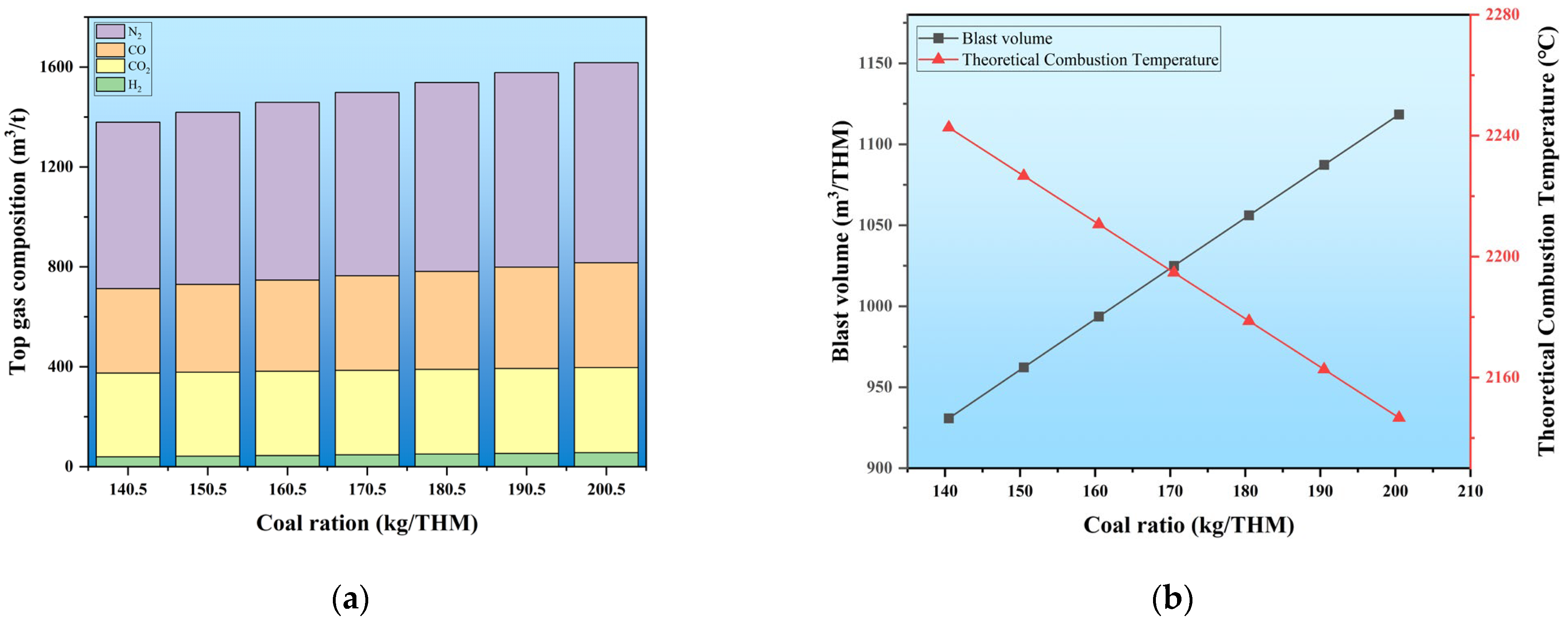
To understand the range of coal and CBM injection quantities after the blast furnace transformation under hydrogen-rich conditions, the coal injection quantity of the traditional blast furnace is defined using a model. The initial conditions are set: a coke ratio of 346.3 kg/THM, a coal ratio of 155.5 kg/THM, a step increase of 5 kg/THM for the coal ratio, and an oxygen enrichment rate of 6%. As the coal ratio increases, the changes in the gas composition in the furnace, the blast volume, and the theoretical combustion temperature are illustrated in Figure 5.
With the increase in the amount of coal injected into the furnace, Figure 5a shows the variation in the content of gas components within the furnace. Notably, CO, N2, and H2 levels exhibit a significant rise. Under the basic furnace conditions, for every 10 kg/THM increase in the coal injection quantity, the average increments of CO, N2, and H2 are 13.61 m3/THM, 22.46 m3/THM, and 2.84 m3/THM, respectively, with increase rates of 3.73%, 3.15%, and 6.41%.
As the coal injection quantity increases, the demand for blast air also rises to maintain stable and smooth furnace operation, increasing N2 content within the furnace hearth. Additionally, due to the excess carbon, the combustion at the tuyere reaches its threshold, increasing the proportion of incomplete carbon combustion. The water–gas reaction intensifies, with reaction products including H2 and CO, as shown in Reactions (7) and (9), which increases the CO content in the furnace hearth. Simultaneously, as the amount of coal powder increases, the hydrogen and water introduced into the system also increase, leading to a rise in H2 content in the furnace hearth. As the pulverized coal injection rate increases within the blast furnace, the CO2 content remains relatively constant at 338.22 m3/THM. This stability is due to the constraints imposed by the input quantity of blended iron ore and the inherent limitations of the blast furnace itself. In summary, as the pulverized coal injection rate increases, the top gas volume rises correspondingly.
In conclusion, with the progressive increase in coal injection quantity, the proportion of reducing gases increases by as much as 17.28%. This change facilitates the smooth conduction of the reduction reaction. However, considering the limitations of theoretical combustion temperature and economic benefits, the optimal carbon consumption value must be calculated. Figure 5b presents the variations in blast volume and theoretical combustion temperature. As coal injection increases, the oxygen input to the furnace must be enhanced, which raises the blast volume, while the theoretical combustion temperature shows a downward trend. For every 10 kg/THM increase in coal injection, the Tf decreases by approximately 16.28 °C. The boundary coal injection quantity must be calculated to keep the Tf within the normal range (2100 °C to 2250 °C). After computation, under these initial conditions, the coal injection quantity should fall within the 136.02 kg/THM to 228.14 kg/THM range.

3.3. Effect of CBM Injection on Pulverized Coal Injection and Oxygen Enrichment

The original working conditions are set as the initial baseline. Figure 6 illustrates the impact of the CBM preheating temperature and injection volume on the coal ratio and the oxygen enrichment rate of the blast furnace air.
Firstly, as the injection volume of CBM increases, the coal ratio shows a linear downward trend. When the preheating temperature of CBM is 25 °C, for every increase of 10 m3/THM in CBM, the coal ratio decreases by approximately 8.08 kg/THM. Under these conditions, when the CBM injection volume reaches 120 m3/THM, the coal ratio decreases from 170.5 kg/THM to 73.27 kg/THM, while the oxygen enrichment rate of the blast increases from 4.28% to 10.30%. This phenomenon occurs because when room-temperature CBM is injected into the blast furnace, it must be heated to the combustion temperature at the tuyere–raceway zone, requiring additional heat from pulverized coal combustion, thereby increasing the oxygen enrichment rate of the blast. Additionally, injecting cold gas into the furnace reduces the coal ratio. It induces internal pressure changes in equipment like gas guns due to the alternation of hot and cold, significantly impacting the service life of the equipment.
In summary, to further enhance the reduction potential of CBM, the CBM was preheated to temperatures of 400 °C, 800 °C, and 1200 °C before injection into the blast furnace. Through model calculations, the effects of CBM injection volume at different preheating temperatures on the coal ratio and oxygen enrichment rate were obtained, as shown in Figure 6. When the CBM injection rate is relatively low, the physical heat brought in by the CBM is minimal, and changing the preheating temperature does not significantly affect the reduction in the coal ratio. Compared to the room-temperature condition, when the preheating temperature is 1200 °C and the CBM injection volume is 10 m3/THM, the coal ratio decreases by 0.421 kg/THM.
However, as the CBM injection volume increases, preheating the CBM significantly reduces the coal ratio in the blast furnace. When the CBM injection volume reaches 120 m3/THM, the coal ratio under room temperature decreases to 74.51 kg/THM. In contrast, at a preheating temperature of 1200 °C, it drops to 22.9 kg/THM, a reduction of approximately 69.26%.
As the preheating temperature of coalbed methane increases, the reduction in the coal ratio becomes more pronounced. Therefore, to maintain the energy and mass balance of the blast furnace system, it is necessary to supply additional physical heat through the blast, requiring an increase in blast volume. Since the blast temperature is fixed, the oxygen enrichment rate must be reduced to accommodate the increased blast volume. When 120 m3/THM of coalbed methane is injected into the blast furnace at room temperature and a preheating temperature of 1200 °C, the oxygen enrichment rate of the blast decreases from 10.30% to 6.81%. As the preheating temperature of coal mine gas inside the blast furnace increases, the pulverized coal injection rate decreases significantly. To maintain the energy and mass balance of the entire blast furnace system, it becomes necessary to increase the blast volume to supply additional thermal energy. Since the blast temperature is fixed, and elemental balance must be preserved during operation, the oxygen enrichment rate must be reduced to accommodate the higher blast volume. This explains the observed trend in the curve.

3.4. Effect of CBM Injection on the Raceway Adiabatic Flame Temperature

Previous studies have established that injecting CBM into the furnace to reduce the coal ratio is an effective carbon reduction technology. However, with the introduction of a significant amount of hydrogen elements, the temperature within the furnace may decrease [10]. Reducing the coal ratio is crucial to ensuring the stable operation of the blast furnace.
A key parameter is required to assess the blast furnace’s thermal variations and operational performance. Since the majority of the heat needed in the metallurgical production of the blast furnace is supplied by the combustion of fuel at the tuyere–raceway zone, the variation in Raceway Adiabatic Flame Temperature (RAFT) serves as an important indicator of the thermal state of the furnace. The RAFT is a critical parameter for evaluating blast furnace operation. As blast furnace smelting calculations have evolved, numerous scholars have refined heat balance models, improving their accuracy. The adiabatic flame temperature calculation model is presented as Equation (17).
R A F T = Q c a r b o n + Q K S + Q m e t h a n e Q 4 , Q M d e c o m Q s l a g g i n g C ¯ p g × V G a s r + C ¯ K A s h × m K A s h + C ¯ M A s h × m M A s h + C ¯ M n o t × m M n o t
Furthermore, CBM is a biofuel with a relatively high hydrogen content. To maintain the thermal equilibrium of the blast furnace, the RAFT should be controlled to remain above 1900 °C [21], and the T_top should be kept above 130 °C. 
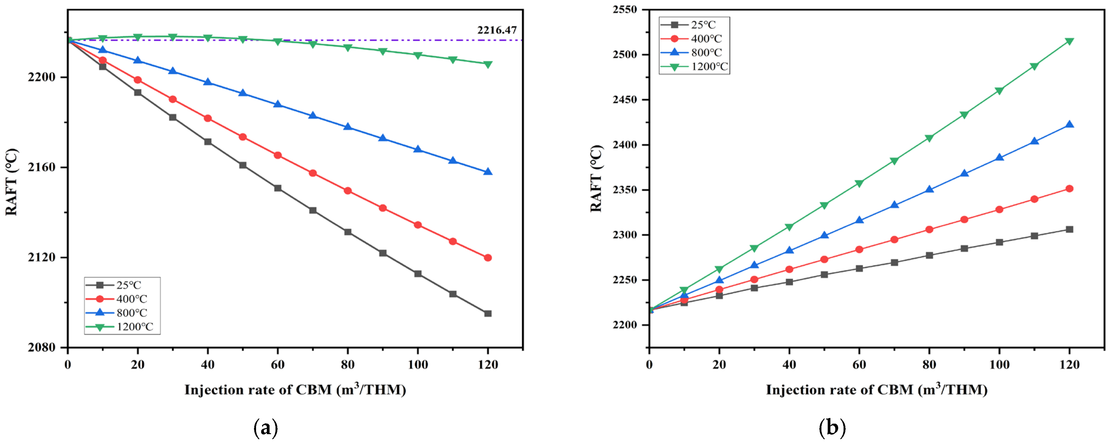
Figure 7a,b show the effects of injecting CBM at different preheating temperatures on the RAFT, with the original smelting parameters unchanged and the coal ratio varying, as shown in Figure 6. The initial RAFT is set at 2216.47 °C, the initial T_top is set at 160 °C, the oxygen enrichment rate is 6%, and the injection temperatures of CBM are set at 25 °C, 400 °C, 800 °C, and 1200 °C, respectively.
When CBM is injected into the system, the RAFT exhibits a downward trend. This occurs because CBM, initially at room temperature, must absorb heat to reach the furnace belly temperature after entering the system. Additionally, methane pyrolysis at high temperatures is an endothermic reaction, as shown in Equation (16).
However, preheating the CBM can effectively alleviate this issue. Initially, when CBM is injected into the furnace at room temperature, and the injection volume reaches 120 m3/THM, the RAFT decreases from 2216.47 °C to 2095.11 °C, a reduction of 5.48%. According to the iterative model, when the CBM injection rate increases to 425 m3/THM, the RAFT further drops to 1902.74 °C. Due to the limitations mentioned earlier, the CBM injection volume is limited. Exceeding this volume could lead to cooling issues in the furnace and disrupt its operation. To further enhance the RAFT and ensure the furnace’s stability and efficiency, CBM was preheated to 400 °C, 800 °C, and 1200 °C.
When the CBM injection volume reaches 120 m3/THM after preheating to 400 °C, the RAFT decreases from 2216.47 °C to 2119.86 °C, a reduction of 4.36%. This is because, at the hot air temperature, CBM enters the furnace without needing to absorb heat from the environment to reach the reaction temperature. Additionally, preheating provides the necessary heat for the decomposition of CBM. This effect can be observed in the furnace’s top temperature variation curve.
However, the RAFT slightly increases when CBM is preheated to the hot air temperature (i.e., 1200 °C), and the injection rate is between 0 and 59.81 m3/THM. In this case, the physical heat from the preheated CBM and the heat released by combustion help compensate for the system’s heat deficit.
As shown in Figure 7b, when the coal and CBM substitution ratio from Figure 6 is applied to the model calculations, an increasing CBM injection rate leads to a corresponding increase in the oxygen enrichment of the blast air. Under these conditions, RAFT’s downward trend halts and rises with the increasing CBM injection rate. Similarly, the RAFT increases with the CBM injection rate, with preheating further amplifying this increase. Initially, when CBM enters the furnace at ambient temperature, an injection rate of 120 m3/THM results in the RAFT rising to 2306.16 °C, a 4.05% increase compared to the previous year. When CBM is preheated to 400 °C and the injection rate reaches 120 m3/THM, the RAFT increases to 2351.46 °C, marking a 6.09% year-on-year increase.
In conclusion, preheating CBM before its injection into the blast furnace significantly improves its stability and efficiency. However, preheating incurs certain economic costs, and from an economic standpoint, the optimal preheating temperature for CBM should be further investigated.

3.5. Effect of CBM Usage on Carbon Dioxide Emissions

According to previous research findings, substituting pulverized coal with CBM has become an effective process for carbon reduction in metallurgical operations. Throughout the smelting process, each parameter contributes to CO2 emissions. Researchers proposed a CO2 emission calculation method that aligns with modern production conditions, incorporating a set of measured emission factors to ensure calculation accuracy [22].
The CO2 emissions from the blast furnace process are calculated as the CO2 equivalent at the input end minus the carbon emission allowance discount at the output end. The calculation results under baseline conditions are presented in Table 11.
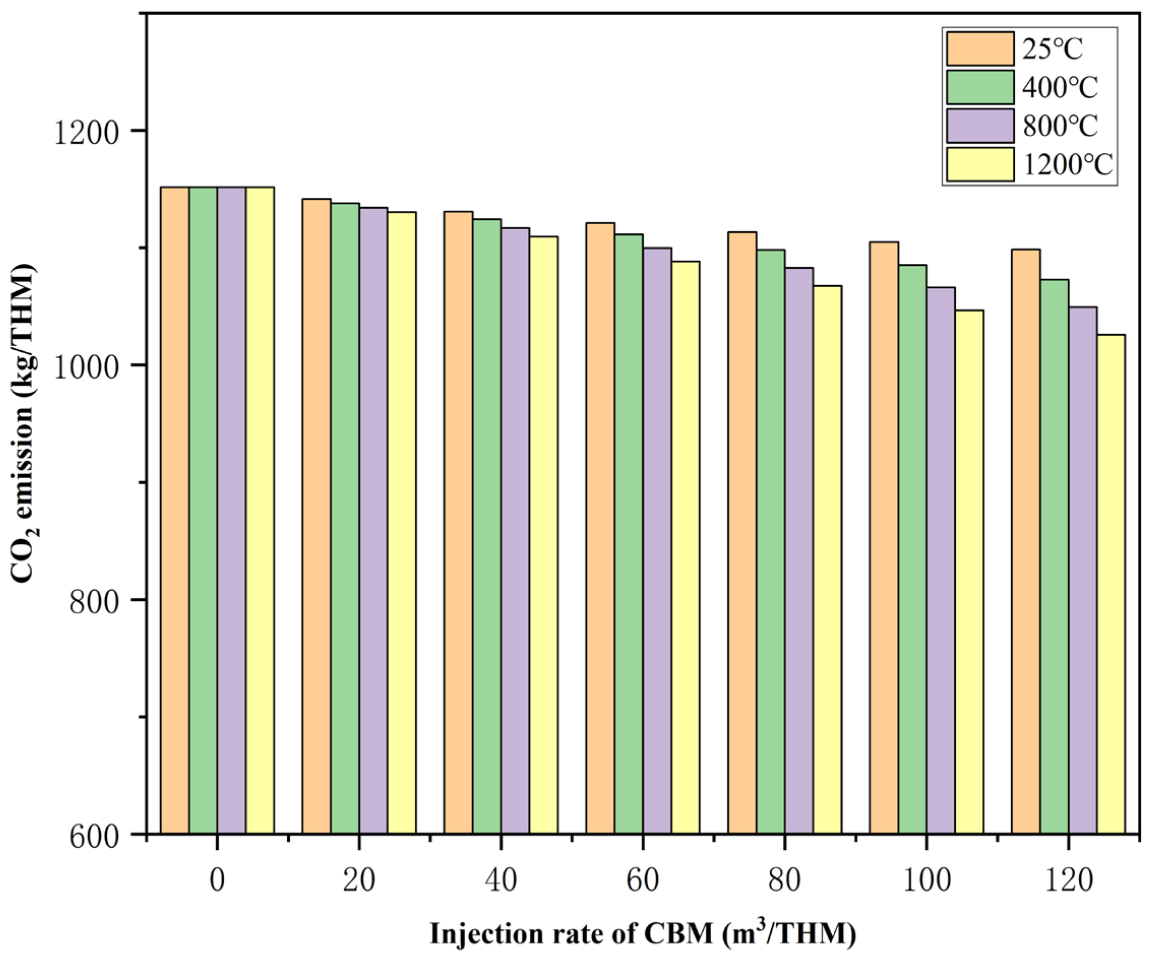
Through model calculations and analysis, we examined the impact of CBM injection volume and preheating temperature on smelting process CO2 emissions, as shown in Figure 8. As room-temperature CBM increases, CO2 emissions decrease. For every 20 m3/THM increase in the CBM injection volume, CO2 emissions decrease by approximately 8.85 m3/THM. As both the preheating temperature and injection volume of CBM increase, the carbon reduction potential of the process rises significantly. Compared to baseline conditions, when the CBM injection volume reaches 120 m3/THM at room temperature and a preheating temperature of 1200 °C, CO2 emissions are 1098.40 m3/THM and 1025.91 m3/THM, respectively, representing reductions of approximately 4.61% and 10.91%.
In conclusion, utilizing CBM to replace a portion of pulverized coal and preheating the injected CBM is a highly effective carbon reduction strategy. This approach offers valuable insights for introducing hydrogen-rich blast furnaces and developing hydrogen-to-coal replacement technologies.

4. Conclusions

This research explored the influence of CBM injections on the smelting parameters of hydrogen-rich blast furnaces under various conditions. The main conclusions are as follows:
  • A mathematical model for the energy and mass balance of the traditional blast furnace was developed based on existing process parameters. Subsequently, this model was updated for hydrogen enrichment and subjected to constraints and iterations according to the boundary conditions. This resulted in the hydrogen-rich blast furnace’s energy and mass balance model.
  • The effects of the CBM injection rate and temperature, coal ratio, and oxygen enrichment rate in the blast furnace were investigated. The replacement ratio of pulverized coal with CBM at different temperatures was calculated based on the heat loss from the blast furnace and the gas limits within the furnace belly.
  • The RAFT and T_top were selected as inspection parameters to ensure the stable and efficient operation of the hydrogen-rich blast furnace. The impact of CBM injection volume under different preheating conditions was examined. As the CBM’s preheating temperature increased, the downward trend of the RAFT slowed, and when the physical heat from the CBM reached a certain threshold, the RAFT increased.
  • As the preheating temperature and injection volume of CBM increased, the process’s carbon reduction potential rose significantly. Compared to baseline conditions, when the CBM injection volume reached 120 m3/THM at room temperature, and a preheating temperature of 1200 °C, CO2 emissions decreased from 1151.50 m3/THM to 1098.40 m3/THM and 1025.91 m3/THM, respectively.
In conclusion, the mathematical model developed in this research provides valuable guidance for optimizing the hydrogen-replacing-carbon process in blast furnaces.

Author Contributions

Conceptualization, H.D. and Y.Z.; methodology, L.C. and Y.Z.; software, L.C.; validation, H.D., L.C. and Z.Q.; formal analysis, Z.G.; investigation, L.C.; resources, H.D.; data curation, L.C. and Z.Q.; writing—original draft preparation, L.C.; writing—review and editing, H.D. and Y.Z.; visualization, L.C.; supervision, L.H. and Y.W.; project administration, L.H. and Y.W.; funding acquisition, H.D. All authors have read and agreed to the published version of the manuscript.

Funding

This work was supported by the National Natural Science Foundation of China (No. U24A20102, 52204350, U21A2045, U23A6013, 52201226), the Key Scientific Research Project in Shanxi Province (Grant No. 202201050201011, 202102050201010, 20220109031014, and 2022ZDYF040), the Special fund for Science and Technology Innovation Teams of Shanxi Province (202204051001004), the International Science and Technology Cooperation and Exchange Special Project in Shanxi Province (2022SZ-TD007), Shanxi-Zheda Institute of New Materials and Chemical Engineering (2022SZ-TD007), and the key research project of Taiyuan city (2024TYJB0112).

Data Availability Statement

The raw data supporting the conclusions of this article will be made available by the authors on request.

Conflicts of Interest

The authors declare no conflicts of interest. The funders had no role in the design of the study; in the collection, analyses, or interpretation of data; in the writing of the manuscript; or in the decision to publish the results.

Abbreviations

Athe ore used to make each ton of ironkg/THM
Kcoke ratiokg/THM
Mcoal ratiokg/THM
T m i r o n molten iron temperature°C
P t o p top pressurekpa
T t o p top temperature°C
T b l a s t hot blast temperature°C
T f theoretical combustion temperature°C
r O e oxygen enrichment rate%
Q c a r b o n carbon oxidation and heat releaseGJ/t
Q b l a s t blast physical heatGJ/t
Q r e s t o r e oxide reduction heat releaseGJ/t
Q s l a g g i n g heat of slaggingGJ/t
Q c h a r g e physical heat of chargeGJ/t
Q 1 heat consumption for oxide decompositionGJ/t
Q 2 heat consumption for desulfurizationGJ/t
Q 3 heat consumption for carbonate decomposition (or effective heat consumption)GJ/t
Q 4 heat consumption for pulverized coal injection decompositionGJ/t
Q 5 heat carried away by molten iron and slagGJ/t
Q 6 heat carried away by top gasGJ/t
Q 7 heat consumption for moisture evaporation in the burden, etc.GJ/t
Q 8 blast-furnace heat lossGJ/t
Q K S the coke is brought into sensible heatGJ/t
Q m e t h a n e physical heat and pyrolysis heat release of methanekJ/t
Q M d volatilization decomposition of pulverized coal consumes heatkJ/t
C ¯ p g average heat capacity of gaskJ/(kg·°C)
V g a s r gas volume at the racewaym3/THM
C ¯ K a s h , C ¯ M a s h the average heat capacity of coke ash and coal ashkJ/(kg·°C)
m K a s h , m M a s h ash weight of coke and pulverized coalkg/t
C ¯ M n o t the average heat capacity of pulverized coal without combustionkJ/(kg·°C)
m M n o t the quality of pulverized coal without combustionkg/t
B M e r r o r material balance relative error%
r Q l o s s total furnace heat loss%
Q C heat from incomplete combustion of carbonkJ/t
Q K , Q M physical heat brought in by coke, coalkJ/t
Q H 2 O d , Q M d , Q C H 4 d heat consumption due to the decomposition of H2O in the blast and coal in the H2-rich gaskJ/t
c g a s heat capacities of hearth gaskJ/(kg·°C)
A K a s h , A M a s h mass fraction of ash in coke and coalKg/t

References

  1. Huang, J.; Zhang, X. Recently amplified arctic warming has contributed to a continual global warming trend. Nat. Clim Chang. 2017, 7, 875–879. [Google Scholar] [CrossRef]
  2. Frölicher, T.L.; Fischer, E.M. Marine heatwaves under global warming. Nature 2018, 560, 360–364. [Google Scholar] [CrossRef]
  3. Daud, A.; Jiang, W. Environmental stewardship: Analyzing the dynamic impact of renewable energy, foreign remittances, and globalization index on China’s CO2 emissions. Renew. Energy 2022, 201, 418–425. [Google Scholar]
  4. Tang, L.; Xue, X. Iron and steel industry emissions and contribution to the air quality in China. Atmos. Environ. 2020, 237, 117668. [Google Scholar] [CrossRef]
  5. Pei, M.; Petäjäniemi, M. Toward a Fossil Free Future with HYBRIT: Development of Iron and Steelmaking Technology in Sweden and Finland. Metals 2020, 10, 972. [Google Scholar] [CrossRef]
  6. Hou, B.; Zhang, H. Study on Kinetics of Iron Oxide Reduction by Hydrogen. Chin. J. Chem. Eng. 2012, 20, 10–17. [Google Scholar] [CrossRef]
  7. Jozwiak, W.K.; Kaczmarek, E. Reduction behavior of iron oxides in hydrogen and carbon monoxide atmospheres. Appl. Catal. A Gen. 2007, 326, 17–27. [Google Scholar] [CrossRef]
  8. Tang, J.; Chu, M. Development and progress on hydrogen metallurgy. Int. J. Miner. Metall. Mater. 2020, 27, 713–723. [Google Scholar] [CrossRef]
  9. Gudiyella, S.; Buras, Z. Modeling study of high temperature pyrolysis of natural gas. Ind. Eng. Chem. Res. 2018, 57, 7404–7420. [Google Scholar] [CrossRef]
  10. Wang, G.; Xu, J. Heat distribution model under hydrogen-rich low-carbon conditions in blast furnace. J. Iron Steel Res. Int. 2024, 31, 584–594. [Google Scholar] [CrossRef]
  11. Qu, Y.; Song, S. Mathematical Modeling for the Process of Smelting Reduction Ironmaking Integrated with Hydrogen-Rich Coal Gasification. Processes 2024, 12, 370. [Google Scholar] [CrossRef]
  12. Guo, H. Physicochemical principles of hydrogen metallurgy in blast furnace. J. Iron Steel Res. Int. 2024, 31, 46–63. [Google Scholar] [CrossRef]
  13. Yanagisawa, Y. Testing for the equivalence of several sets of time series and its multiple comparison procedure. Commun. Stat. Theory Methods 2023, 52, 3149–3164. [Google Scholar] [CrossRef]
  14. David, H.A.; Paulson, A.S. The performance of several tests for outliers. Biometrika 1965, 52, 429–436. [Google Scholar] [CrossRef]
  15. Han, Y.H.; Wang, J.S. Comprehensive mathematical model of top gas recycling-oxygen blast furnaces. Chin. J. Eng. 2011, 33, 1280–1286. [Google Scholar]
  16. Keller, M.; Matsumura, A. Spray-dried Fe/Al2O3 as a carbon carrier for COx-free hydrogen production via methane cracking in a fluidized bed process. Chem. Eng. J. 2020, 398, 125612. [Google Scholar] [CrossRef]
  17. Abbas, H.F.; Daud, W. Hydrogen production by methane decomposition: A review. Int. J. Hydrogen Energy 2010, 35, 1160–1190. [Google Scholar] [CrossRef]
  18. Spanlang, A.; Wukovits, W. Development of a Blast Furnace Model with Thermodynamic Process Depiction by Means of the Rist Operating Diagram. Chem. Eng. Trans. 2016, 52, 973–978. [Google Scholar]
  19. Perpiñán, J.; Bailera, M. Full oxygen blast furnace steelmaking: From direct hydrogen injection to methanized BFG injection. Energy Convers. Manag. 2023, 295, 117611. [Google Scholar] [CrossRef]
  20. She, X.F.; An, X.W. Numerical analysis of carbon saving potential in a top gas recycling oxygen blast furnace. J. Iron Steel Res. Int. 2017, 24, 608–616. [Google Scholar] [CrossRef]
  21. Chen, B.; Chen, J. Optimization of Raceway Adiabatic Flame Temperature Model for H2-Rich Gas Injection Blast Furnace. J. Sustain. Metall. 2024, 10, 2009–2019. [Google Scholar] [CrossRef]
  22. Ye, S.; Wang, Y. New insights into the influence of hydrogen on important parameters of blast furnace. J. Clean. Prod. 2023, 425, 139042. [Google Scholar] [CrossRef]
Figure 1. Charge behavior and chemical reaction equation in blast furnace.
Processes 13 01702 g001
Figure 2. Division of the blast furnace tuyere–raceway zone. (A. Blast furnace body; B. pulverized coal injection pipe; C. blast lance; D. hydrogen-rich gas injection pipe; E. blast furnace tuyere; F. cohesive zone; G. blast furnace raceway; H. Deadman).
Processes 13 01702 g002
Figure 3. Flowchart of the parameter iteration calculation for the hydrogen-rich blast furnace.
Processes 13 01702 g003
Figure 4. Relationship between carbon consumption and degree of direct reduction in TBF [20].
Processes 13 01702 g004
Figure 5. Variation in key parameters in blast furnace with coal injection. (a) Variation in top gas composition. (b) Variation in blast volume and theoretical combustion temperature.
Processes 13 01702 g005
Figure 6. Impact of CBM injection conditions on coal ratio and oxygen enrichment.
Processes 13 01702 g006
Figure 7. Effects of CBM injection at varying volumes and temperatures on RAFT. (a) CBM injection without changing the original conditions. (b) Condition after coal replacement with CBM injection.
Processes 13 01702 g007
Figure 8. The impact of CBM injection volume and preheating temperature on CO2 emissions in the smelting process.
Processes 13 01702 g008
Table 1. Production indices of the blast furnace after outlier removal (2023).
ProjectAKM T m i r o n P t o p T t o p T b l e s t T f r O e
kg/tkg/tkg/t°Ckpa°C°C°C%
result1670.8346.3170.51510.12259.81160.051200.152216.474.28
Table 2. Chemical analysis of coke and pulverized coal (wt%).
Moisture
Content
TFeFeOSiO2CaOMgOAl2O3H2N2O2
Coke0.030.510.665.760.460.254.480.320.311.66
Coal0.000.510.667.100.530.134.603.672.493.64
Table 3. Elemental composition of Ore (wt%).
TFeFeOFe2O3FeSSiO2CaOMgOAl2O3MnO2SP
Sinter54.499.0267.800.075.5411.502.972.440.580.020.07
Pellet62.281.1687.670.035.881.571.300.620.600.010.05
Lump ore59.520.6984.240.077.672.411.492.261.140.020.19
Mixed ore56.306.7572.900.065.888.832.532.150.660.020.08
Table 4. Elemental composition of the hot metal (wt%).
FeCSiMnTiSP
94.484.570.400.430.050.030.04
Table 5. Full-furnace material balance sheet (kg/t).
Incoming ProjectOutgoing Project
moisture content1670.80pig iron1000
coke (wet)346.3slag373.63
limestone0coal oven gas (wet)2133.48
blast (wet)1327.07furnace dust8.55
coal170.5
aggregate3514.68aggregate3515.66
absolute error1.18relative error0.028%
Table 6. The first full-furnace heat balance meter.
Heat IncomeHeat Expenditure
ProjectHeat GJ/t%ProjectHeat GJ/t%
Q c a r b o n 2.83728.08 Q 1 6.90768.26
Q b l a s t 1.57515.56 Q 2 0.0310.30
Q 3 0.0070.07
Q r e s t o r e 5.70356.38 Q 4 0.1711.69
Q 5 1.99919.76
Q s l a g g i n g 0.0020.02 Q 6 0.3093.05
Q 7 0.0010.001
Q c h a r g e 00 Q 8 0.6916.83
aggregate10.118100aggregate10.118100
Table 7. Composition of coalbed methane (CBM) per unit volume (vol%).
CH4CO2N2O2Heavy Hydrocarbon
97.30.2621.520.1450.101
Table 8. Calculated values of the direct reduction degree under ten sets of computational parameters.
Working ConditionCoke RatioCoal RatioConsumption per ton of Iron OreHot Air TemperatureInitial Direct Reduction Degree
Unitskg/tkg/tkg/t°C——
1310.5167.51645.0212350.4310
2328.9171.71732.0612370.4285
3326.9162.21689.6712180.4333
4324.1163.11661.8712190.4328
5344.0172.91700.1212110.4262
6330.8151.71645.8412170.4398
7347.1162.61745.1212010.4320
8332.0142.41613.4412000.4447
9335.4141.81653.4911850.4441
10351.8132.41615.1211900.4505
Table 9. The relevant parameters obtained from the model calculation and verification.
Number123456789
K344.0351.8360.4348.7329.6333.6335.0325.4324.7
M160.1162.4151.2139.1169.0169.7159.4166.3162.7
r O e 4.724.203.862.995.355.204.665.174.05
T t o p 1091259598157139123138143
T b l a s t 115911901175118912181210120312391240
B M e r r o r 0.0360.0340.0230.0380.0400.0370.0390.0430.040
r Q l o s s 5.326.737.024.624.084.994.404.074.83
T f 217721962203223222072200221122262232
Table 10. The composition of the top gas obtained from the model calculation and the measured values from actual production.
ProjectCO2CON2H2H2O
Model calculation result, %21.44724.03748.3023.0213.193
Field measurement result, %22.023.552.421.77
Table 11. Calculation model for CO2 emissions in the blast furnace process.
Input EndOutput End
ProjectEquivalent CO2 Amount/kgProportion/%ProjectEquivalent CO2 Amount/kgProportion/%
K1093.2766.63%Molten iron167.4410.21%
M482.5029.41%BFG entering the pipeline
network
315.9119.25%
CBM00.00%Furnace dust5.870.36%
Electricity consumption64.953.96%Process CO2 emissions1151.5070.18%
Sum up1640.73100%Sum up1640.73100%
Disclaimer/Publisher’s Note: The statements, opinions and data contained in all publications are solely those of the individual author(s) and contributor(s) and not of MDPI and/or the editor(s). MDPI and/or the editor(s) disclaim responsibility for any injury to people or property resulting from any ideas, methods, instructions or products referred to in the content.

