Abstract
This paper proposes a supercapacitor-battery hybrid energy storage scheme based on a series-parallel hybrid compensation structure and model predictive control to address the increasingly severe power quality issues in oilfield microgrids. By adopting the series-parallel hybrid structure, the voltage compensation depth can be properly improved. The model predictive control with a current inner loop is employed for current tracking, which enhances the response speed and control performance. Applying the proposed hybrid energy storage system in an oilfield DC microgrid, the fault-ride-through ability of renewable energy generators and the reliable power supply ability for oil pumping unit loads can be improved, the dynamic response characteristics of the system can be enhanced, and the service life of energy storage devices can be extended. This paper elaborates on the series-parallel compensation topology, operational principles, and control methodology of the supercapacitor-battery hybrid energy storage. A MATLAB/Simulink model of the oilfield DC microgrid employing the proposed scheme was established for verification. The results demonstrate that the proposed scheme can effectively isolate voltage sags/swells caused by upstream grid faults, maintaining DC bus voltage fluctuations within ±5%. It achieves peak shaving of oil pumping unit load demand, recovery of reverse power generation, stabilization of photovoltaic output, and reduction of power backflow. This study presents an advanced technical solution for enhancing power supply quality in high-penetration renewable energy microgrids with numerous sensitive and critical loads.
1. Introduction
With the advancement of renewable energy power generation and the increasing demand for electric power in oilfields [1], the grid structure is facing random fluctuations in both power generation and load, and the power supply mode in oilfields is undergoing a historic change. The conventional AC power grid employs reactive power compensation to stabilize the voltage and depends on AC circuit breakers to realize trend adjustment. However, it struggles to meet the requirements of renewable energy power generation and random load fluctuations for the grid’s rapid response. Simultaneously, the traditional approaches of reliance on diesel power generation or long-distance AC transmission are plagued by high energy consumption, high pollution, and cost pressure.
DC microgrids have emerged as a crucial avenue for upgrading oilfield energy systems with their advantages of efficient transmission, flexible configuration, and easy integration of renewable energy sources [2]. Establishing a DC grid to interconnect renewable energy sources with traditional energy sources over a wide area can fully realize the complementarity between multiple forms of energy, multiple time scales, large spatial spans, and multiple user types, and it is an important development direction for the future power grid. By integrating clean energy sources such as photovoltaic and wind power, combined with energy storage and control technology, the oilfield DC grid can not only solve the power supply problems of remote oilfields and offshore oilfields. Moreover, it can significantly reduce carbon emissions and improve the efficiency of energy use [3,4]. Meanwhile, with the maturity of ultra-high voltage flexible DC, smart microgrid, and other technologies, the oilfield DC grid will play a pivotal role in the process of clean energy and provide strong support for the sustainable development of the oil industry.
It is crucial to ensure the safe and stable operation of the oilfield DC grid, and power quality is an important influencing factor. Amid the transition of energy supply and consumption toward green and low-carbon development, traditional oilfield power grids urgently need to integrate large-scale renewable energy to achieve low-carbon transformation. Oilfield DC microgrids represent an advanced technical solution for incorporating distributed renewable energy and powering sensitive oil pumping loads. However, challenges such as the integration of high-proportion volatile renewable energy, voltage disturbances caused by the reverse power generation characteristics of oil pumping loads, and inevitable system short-circuit faults exacerbate the risks of voltage sags/swells and other power quality issues in oilfield DC microgrids. This makes it difficult to meet the power supply quality and reliability requirements for sensitive oil pumping loads. Among them, the compensation of unbalanced voltage/current, voltage sags and swells, power fluctuations, and load fluctuations in oilfield grids have been very challenging power quality problems in microgrids in recent years [5]. This is because the power quality of microgrids is not only related to the operating characteristics of internally distributed power sources, energy storage devices, and various loads in the oilfield, but also interacts with its external connection to the distribution grid.
The utilization of energy storage devices for compensation and regulation can effectively address power quality problems. Since it is difficult for a single energy storage device to simultaneously meet the requirements of both high power and large capacity, hybrid energy storage technology, which is substantially better than a single form of energy storage in terms of economy and performance, has attracted worldwide attention [6,7,8]. A hybrid energy storage (HESS) system mainly features the performance complementarity between energy-type and power-type energy storage units. Through the energy management and power allocation scheme, different energy storage units are coordinately controlled so that they play to their respective advantages in different application scenarios, in order to improve the security and stability of the microgrid.
Currently, the hybrid energy storage technology that has been studied in the literature [9] is composed of batteries and supercapacitors through a parallel connection structure and a power distribution strategy. Wu et al. [10] propose a hybrid energy storage of batteries and ultracapacitors based on an adaptive energy optimization method. After extracting the fluctuating power by the low-pass filter, the battery packs release the power to offset the low-frequency fluctuation load, while the supercapacitor instantaneously compensates the high-frequency fluctuation power, to prolong the service life of batteries and maintain the stability of DC bus voltage. Garcia et al. [11] investigate the advantages of hybrid battery and ultracapacitor technologies, present some existing solutions for coordinating power flow, and propose a new control strategy aimed at improving performance and energy efficiency while extending battery life. Jia et al. [12] propose a supercapacitor cascade structure, where the supercapacitor is connected to the bus by virtue of a dual active full bridge DC-DC converter for smoothing the high-frequency component of the power fluctuations, and to the Li-ion battery by using a bi-directional boost converter for indirectly smoothing the residual low-frequency component. Inoue and Akagi [13] propose a dual active full-bridge DC/DC converter with additional galvanic isolation to increase the safety of the system. Lin et al. [14] propose a bidirectional DC/DC converter topology with coupled inductors based on a Buck/Boost converter to achieve effective control and improve the dynamic response of the load. In [15], a hybrid energy storage system is constructed using a combination of batteries and ultracapacitors, and two frequency-based filtering methods, i.e., the low-pass filtering (LPF) method and the wavelet multilevel Haar transform, are developed under the rule-based power-sharing strategy to control the power flow among energy sources of the HESS and to reduce the overall stress on the batteries in times of high transient power demand.
Ma et al. [16] use a sliding average filtering control scheme to assign the domains with smoother control sequences to the battery and the domains with more fluctuating control sequences to the supercapacitor, which has the effect of optimizing power smoothing. Liao et al. and Nikoobakht et al. [17,18] propose a new virtual filter method and a continuous time method to suppress the frequency fluctuation of the power system, respectively. Sun et al. [19] apply multiple types of energy storage to smooth the power fluctuation of wind power and utilize a first-order low-pass filtering algorithm to achieve power allocation between energy-based battery storage and power-based supercapacitor storage.
Xie et al. [20] propose a strategy to improve the response speed of hybrid energy storage by compensating the prediction error under different operating conditions with first-order control and smoothing the power fluctuation with second-order control. Ma et al. [21] propose a photovoltaic maximum power tracking operating point control and HESS coordinated to smooth PV grid-connected power fluctuation strategy, through the close cooperation between PV and HESS, the PV grid-connected power fluctuation can be effectively suppressed within the acceptable range of the power grid. Liu and Zhang [22] constructed a HESS consisting of batteries and supercapacitors to smooth the power fluctuation of wind power. A power allocation strategy is proposed, which can significantly reduce the number of charging and discharging times of the battery pack by suppressing the low-frequency component of the ultracapacitor current. A DC/AC converter is used to realize the power exchange between the HESS and the grid.
As for the actual applications of MPC-based hybrid energy storage, a PV-powered battery-supercapacitor-fuel cell system is employed in an islanded microgrid [23]. The improvements in energy scheduling, achieved with MPC, are highlighted through comparison with a heuristic-based method, like Fuzzy inference. Almost 50% and 80% reduction in PV power curtailment and dispatchable generators are achieved with the MPC method. A Dual-Model Predictive Control (D-MPC) strategy is adopted to optimize the hybrid operation of superconducting energy storage devices and batteries [24]. The system employs a low-pass filtering strategy combined with MPC to track the current references of the battery and SMES. The results show that the minimum DC bus voltage increased from 634 V (84.53%) under traditional PI control to 738 V (98.4%) under the improved D-MPC control.
However, the above methods allocate hybrid storage power commands based only on the effect of smoothing power fluctuations and the speed of hybrid storage response, but neglect the problems of state of charge (SOC) overrun and insufficient charging/discharging responsiveness that may occur in hybrid storage in actual operation. Li et al. [25] propose an online parameter identification method based on recursive least squares, which can automatically adapt to changes in battery SOC, temperature, and operating conditions, fit and calculate the optimal model parameters, and then ensure the model accuracy. Sun et al. [26] propose a SOC feedback control method based on the predictive value and reference trajectory. It can realize the optimal distribution of HESS energy and increase the service life of the system. Abdurraqeeb et al. [27] propose a new approach that combines R (Regulation), S (Sensitivity), and T (Tracking) control with filter-based technology. The aim of this approach is to ensure the uninterrupted operation of the SC when the system experiences abrupt load changes that cannot be effectively mitigated using conventional filter-based schemes. However, when the filtering time constant is kept constant, the direct correction of the filtered output reference power value will lead to a large gap between the filtered reference value and the corrected value, so that the energy storage cannot be well-suppressed power wave, and the above strategy does not take into account the problem that the very low energy density of supercapacitor can easily lead to the problem of SOC crossing the limit.
To address the above problems, this paper proposes a series-parallel hybrid compensation structure and a hybrid supercapacitor-battery energy storage compensation scheme based on model predictive control (MPC). The voltage compensation depth can be improved by using the series-parallel hybrid compensation structure, and the model predictive control of the current inner loop is used to achieve the purpose of current tracking, which improves the response speed and control performance. The hybrid energy storage for oilfield DC microgrids can improve the fault ride-through capability of renewable energy generator sets and the reliable power supply capability of pumping loads, improve the dynamic response characteristics of the DC system, and prolong the life cycle of the whole energy storage equipment.
2. System Overview
The overall architecture of the proposed hybrid energy storage system is shown in Figure 1. The system is mainly divided into three parts: the power supply part, the load part, and the energy storage part. The power supply part is composed of the AC grid and PV power generation. The AC grid is connected to the DC bus through an AC-DC converter, and the PV power generation is connected to the DC bus through a DC-DC converter. The load part is composed of DC load and oil pumping load, in which the DC load is connected in parallel to the DC bus through a DC-DC converter to supply power, and the oil pumping unit is connected in parallel to the DC bus through an AC-DC converter. The oil pumping unit can be operated in two operating modes: the electric generator and the electric motor. The energy storage part is a supercapacitor-battery hybrid energy storage compensation system employing the proposed series-parallel compensation topology. Based on the functional differences between voltage compensation and power compensation, the supercapacitor-battery energy storage compensation system is decomposed into a series compensation module and a parallel compensation module.
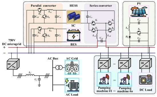
Figure 1.
Overall system architecture of the proposed oilfield microgrid-oriented supercapacitor-battery hybrid energy storage.
The series compensation module consists of a supercapacitor energy storage system and a series full-bridge converter, which is connected in series to the input side of the DC microgrid bus power supply in oilfields. When voltage sag/swell or disturbance events occur in the upstream grid, the energy storage system injects voltage into the DC bus through the series compensation module to mitigate power quality issues, ensuring voltage stability at both the renewable energy generator terminals and the oil pumping load terminals, thereby enhancing the reliability of the supply voltage.
The parallel compensation module comprises a hybrid energy storage system of supercapacitors and batteries, along with two sets of bidirectional buck-boost converters, which are directly connected to the DC bus of the oilfield microgrid. This configuration establishes a responsive power regulation mechanism; in response to photovoltaic output fluctuations within the DC microgrid, the HESS injects compensating currents through the parallel module to mitigate power variations, simultaneously counteracting periodic load disturbances from oil pumping operations. Such dual compensation enables rapid power balance restoration between generation and consumption within the DC microgrid. Notably, the parallel and the series compensation modules maintain electrical isolation through the supercapacitor energy storage system. The parallel compensation module employs the proposed current inner-loop model predictive control method to achieve superior compensation performance for the hybrid energy storage system. Through the coordinated operation of the series-parallel compensation modules in the hybrid energy storage system, the power supply quality and reliability of the oilfield DC microgrid are ultimately enhanced.
3. Power Flow of the HESS System in Oilfield DC Microgrid
The operation mode of the overall system is mainly divided into two modes: night and daytime. During the daytime, the system is powered by both the PV and the AC grid, while at night, it is mainly supplied by the AC grid. In the daytime operational mode, the system gives priority to using PV for power supply. When power fluctuations occur in the DC microgrid bus, the supercapacitor is the first-choice device for compensation. In cases where the supercapacitor cannot supply sufficient power, the system then resorts to the battery for compensation. If the battery’s power supply is also inadequate, the system utilizes the AC microgrid to compensate for the power deficit. During the nighttime operational mode, the system relies solely on the AC microgrid for power supply. In the event of additional load power fluctuations, the system can also employ the battery or supercapacitor for a certain degree of compensation.
For the pumping load, it can operate in two modes: motor mode and generator mode. In motor mode, the oil pumping unit is powered by a combination of photovoltaics, batteries, supercapacitors, and an AC microgrid. In generator mode, the oil pumping unit returns excess energy to the DC bus, and the system absorbs the energy through hybrid energy storage by supercapacitors and/or batteries. When they are also saturated, the excess energy is fed back to the AC grid.
Figure 2 demonstrates the eight operating states under a typical daytime operation. The operating principle and power balance relations are elaborated in detail as follows.
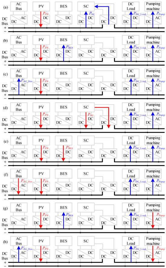
Figure 2.
System power flows of eight modes in a typical daytime operation. (a) Initial power absorption by the supercapacitor, (b) Steady power absorption by the battery, (c) Surplus power feedback for the grid, (d) Initial power compensation from the supercapacitor, (e) Steady power compensation from the battery, (f) Inadequate power supply from the grid.
From Figure 2a, it can be seen that when the excess power of PV power generation causes a transient rise in DC microgrid bus voltage, the excess power is quickly absorbed by the supercapacitor at the very beginning to ensure the normal operation of the DC loads and oil pumping units, i.e., the power balance equation is as follows:
From Figure 2b, it can be seen that after the supercapacitor is charged to the preset threshold, the excess power will continue to be absorbed by the battery, i.e., the power balance equation is as follows:
From Figure 2c, it can be seen that after charging the battery to full capacity, the excess power is sent to the AC microgrid, i.e., the power balance equation is as follows:
From Figure 2d, it can be seen that when the PV power is insufficient, which causes a transient drop in DC microgrid bus voltage, the missing power is compensated quickly by the supercapacitor at the very beginning to ensure the normal operation of the DC loads and oil pumping units, i.e., the power balance equation is as follows:
From Figure 2e, it can be seen that after the supercapacitor is discharged to the preset threshold, the missing power will continue to be compensated by the battery, i.e., the power balance equation is as follows:
From Figure 2f, it can be seen that after the battery is discharged to full capacity, the missing power is compensated by the AC microgrid, i.e., the power balance equation is as follows:
From Figure 2g, it can be seen that when the oil pumping unit generates power in the reverse direction, it causes a temporary rise in the DC microgrid bus voltage, and the excess power is absorbed by the battery to ensure the normal operation of the DC load, i.e., the power balance equation is as follows:
From Figure 2h, it can be seen that after charging the battery to full capacity, the excess power is sent to the AC microgrid, i.e., the equation is as follows:
4. Circuit Principles and Control Strategies of HESS
4.1. Parallel Converter
4.1.1. Circuit Operating Principles and Modeling
The parallel converter consists of bidirectional buck-boost converters corresponding to the supercapacitor and battery connected in parallel. Based on the charging/discharging states of the energy storage system to the DC bus, it operates in two modes with four transient states, as illustrated in Figure 3.
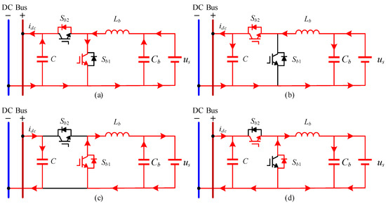
Figure 3.
Working principle of the bidirectional buck-boost circuit for supercapacitor/battery. Discharge operation (a,b). Charge operation (c,d).
Figure 3a,b represent two operational transients within each switching cycle during the energy storage discharging mode. In Figure 3a, the energy storage primarily charges the inductor through Sb1, with minimal current output to the DC microgrid. To simplify the analysis, the influence of this discharging transient on the energy storage is neglected. Consequently, the voltage equations remain identical during both charging and discharging transients, allowing the analysis of either case to suffice.
When Sb1 is turned on and Sb2 is turned off, the circuit operation equations are the following:
When Sb1 is turned off and Sb2 is turned on, the circuit operation equations are the following:
Simultaneous (9) and (10) to obtain the average value model of the converter (Let the PWM duty cycle of s1 be d).
Using small signal perturbations to deal with the relevant variables, the following results are:
where the average value of UC, ILb, US, D, Idc-uc, iLb, us, d, idc; the disturbance is denoted by a superscript ^.
Thus, the inverter linearization model results from Equation (11) by ignoring the quadratic and perturbation terms
Equation (13) is obtained by the Laplace transform
Eliminate ûs(s) in Equation (14) to obtain
Sorted out
Thus, the transfer function from the duty cycle to the inductor current is
Ignoring the power loss and inductance of the switch, we get
Then the transfer function of the output current and the inductor current is
After discretizing Equation (11) based on the forward Euler method, obtain
where Ts—sampling period.
The final discrete expression for the output voltage and the input inductor current is
4.1.2. Power-Current Dual-Loop Control Strategy
Based on the fundamental control concept of hybrid energy storage, this paper integrates a power outer-loop control with an MPC current inner-loop control featuring delay compensation to enhance the current inner-loop, thereby forming a dual closed-loop control structure. The power outer-loop provides a reference current for the current inner-loop, while a low-pass filter is designed to decompose the compensation current of the hybrid energy storage, obtaining the high- and low-frequency components of the reference current for the supercapacitor and battery. Further, the control signals for the converter are derived through model predictive control. The dual closed-loop control structure is illustrated in Figure 4.
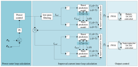
Figure 4.
Power-current dual-loop control strategy for parallel converter.
4.1.3. Predictive Control Strategy of Current Inner Loop Model
In this paper, a stable continuous set model predictive control algorithm is used for the current inner loop control strategy. Let the cost function (control quantity is inductance current) be
where iLb_ref—the current reference value of the current in the inner loop.
Substituting Equation (21) into Equation (22), we get
Equation (23) finds the partial derivative of d and makes the result is 0.
Sorted out
The upper and lower limits of the inductor current are set to iLb_max, iLb_min for the duty cycle of the next control cycle, that is
Sorted out
As can be seen from Equation (27), the duty cycle limits the magnitude of the inductor current.
Compared with traditional control strategies such as PI, the parameters of the current inner loop model predictive control strategy are only related to the self-properties of the circuit and the control cycle. Figure 5 shows the block diagrams of the MPC current inner loop and converter current inner loop control system. As can be seen from Figure 5, the closed-loop transfer function from iLb_ref to iLb is
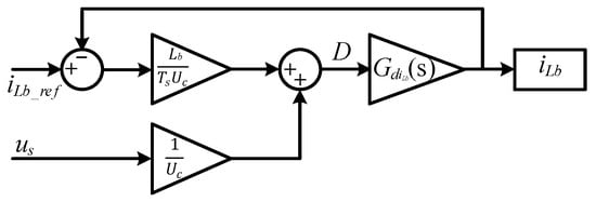
Figure 5.
Principle of inductor current calculation in closed-loop control of bidirectional buck-boost converters.
The closed-loop transfer function from us to iLb is
Substituting Equation (17) into Equations (28) and (29), respectively, we obtain
4.2. Series Converter
4.2.1. Circuit Operating Principles and Modeling
As shown in Figure 6, the supercapacitor series compensation module compensates the DC bus voltage through the output voltage of the full-bridge converter. Depending on the direction of the output compensation voltage, the supercapacitor full-bridge converter operates in two modes: forward voltage compensation and reverse voltage absorption. In forward voltage compensation mode, the supercapacitor CSC functions as a power source, while the capacitor Cssf serves as a load-side stabilizing capacitor. The supercapacitor releases energy to compensate for insufficient voltage on the DC bus. In reverse voltage absorption mode, capacitor Cssf acts as the power source, and the supercapacitor CSC becomes the load. By absorbing energy, the voltage across the capacitor Cssf becomes negative, thereby maintaining the stability of the DC bus voltage.
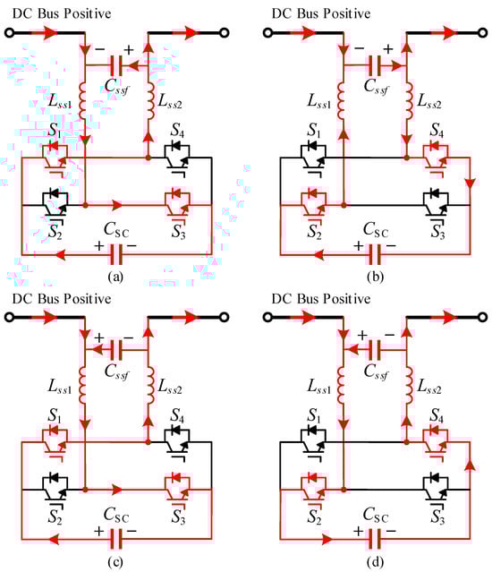
Figure 6.
Principle of series compensation in full-bridge circuits for supercapacitors. Forward voltage compensation operation. (a,b). Reverse voltage compensation operation (c,d).
Depending on the conduction states of power switches S1 to S4, the full-bridge converter exhibits two operational transients in each operating mode. Taking the supercapacitor discharge as an example, these are illustrated in Figure 6a,b. To simplify the analysis, inductors Lss1 and Lss2 are collectively considered and defined as Lss. When S1 and S3 are turned on while S2 and S4 are turned off, the equivalent circuit equation for the supercapacitor discharge loop is expressed as
when S2 and S4 are turned on while S1 and S3 are turned off, the equivalent circuit equation can be expressed as
The charging and discharging current of capacitor Cssf is expressed as
Define the ratio of the conduction time of S1 and S3 to the period within one cycle as the duty cycle D1, and the average compensation voltage on capacitor Cssf is
4.2.2. Control Strategy
Figure 7 presents the control strategy diagram of the supercapacitor series converter. Measured load voltages serve as input signals. Proportional-integral (PI) controllers regulate the discrepancies between reference and actual signals. The PI controllers generate the output duty cycle D1 by adding an offset constant of 0.5. Comparing the duty cycle D1 with the triangular carrier yields the control signals for S1~S4.
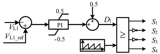
Figure 7.
Control strategy for the series converter.
5. Case Study and Analysis
5.1. Case Configuration
The proposed series-parallel hybrid energy storage system combining supercapacitors and batteries, along with its control strategy, was technically validated using a MATLAB/Simulink R2021b simulation framework. As illustrated in Figure 1 and Figure 8, a detailed DC microgrid model specifically tailored for oilfield applications was constructed, with its operational parameters comprehensively documented in Table 1. The case oilfield’s DC microgrid employs a 750 V monopolar power supply structure, which specifically includes a 100-kW distributed photovoltaic generation unit and ten oil pump loads, each with a maximum operating power of 30 kW. The configuration parameters of the supercapacitor-battery hybrid energy storage system are presented in Table 1, wherein the switching frequency of the series and parallel compensation module inverter is set to 10 kHz. The system’s performance was rigorously evaluated across the following four critical dimensions:
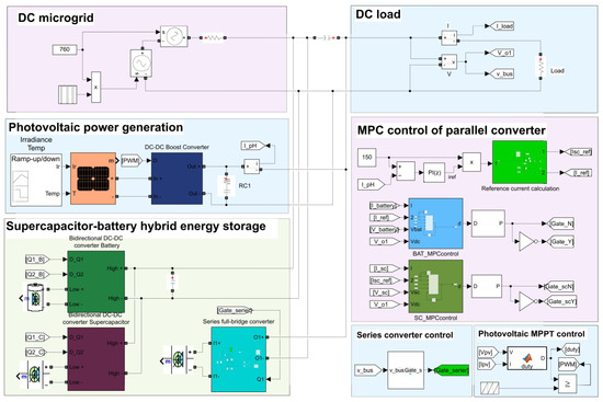
Figure 8.
Simulation model of the oilfield DC microgrid in MATLAB/Simulink.

Table 1.
Parameters of the DC microgrid system in oilfields.
- (1)
- Mitigation capability against grid voltage sag/swell disturbances.
- (2)
- Photovoltaic output fluctuation mitigation through dynamic power smoothing.
- (3)
- Voltage fluctuation suppression and energy recovery during oil extraction cycles and reverse power generation operations.
- (4)
- Pulse load rapid power compensation is employed to stabilize the DC bus voltage.
5.2. Voltage Sags and Swells
When symmetric faults (such as three-phase faults) or asymmetric faults (such as single-phase or two-phase short-circuit faults) occur in the upper-level AC grid of an oilfield DC microgrid, the voltage on the power supply side of the DC microgrid will experience an instantaneous voltage sag or swell. According to the grid-connection requirements, the DC microgrid must possess low-voltage/high-voltage fault ride-through capability. On the one hand, this ensures the safe operation of the microgrid without disconnection from the grid; on the other hand, it guarantees a secure connection and reliable power supply for sensitive renewable energy generation units and pumping unit loads within the DC microgrid.
To verify the compensation performance of the supercapacitor series compensation module in the proposed scheme for voltage sag/swell power quality issues, voltage sag/swell events on the grid side were configured as shown in Figure 9(a1,a2), with the specific details as follows:
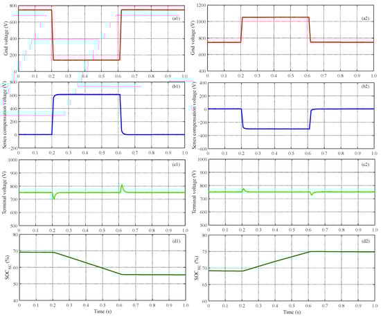
Figure 9.
Voltage sag and swell mitigation performance of HESS in oilfield DC microgrids. (a1) Grid voltage in voltage sag, (b1) HESS series compensation voltage in voltage sag, (c1) Terminal voltage in voltage sag, (d1) SOC of supercapacitor in voltage sag, (a2) Grid voltage in voltage swell, (b2) HESS series compensation voltage in voltage swell, (c2) Terminal voltage in voltage swell, (d2) SOC of supercapacitor in voltage swell.
Case 1: A voltage sag event with an amplitude of 600 V (0.8 p.u.) occurs on the grid-side input voltage and lasts 400 ms, as illustrated in Figure 9(a1).
Case 2: A voltage swell event with an amplitude of 300 V (0.4 p.u.) occurs on the grid-side input voltage and lasts 400 ms, as depicted in Figure 9(a2).
In Case 1, when an input voltage sag occurs in the oilfield DC microgrid, the supercapacitor energy storage system injects a 600 V series voltage into the DC bus through the series full-bridge converter (Figure 9(b1)), rapidly responding to release electrical energy to maintain the terminal voltage of the DC microgrid at 750 V. This ensures the safe grid connection of distributed photovoltaic power generation units and a reliable power supply to the pumping unit loads. As shown in Figure 9(c1), the terminal voltage of the DC microgrid exhibits only minor fluctuations (<±7%) at the instant of voltage sag occurrence (0.2 s) and clearance (0.6 s), quickly recovering to the rated voltage and remaining within the 90~110% fluctuation range required for power supply. During the 400 ms sustained fault demonstrated in the case, the supercapacitor releases 39.38 kJ of energy, with its state of charge (SOC) decreasing from 69% to 55%.
Similarly to Case 1, when addressing the input voltage swell in Case 2 (Figure 9(a2–d2)), the supercapacitor series compensation module rapidly absorbs the 300 V overvoltage, maintaining the terminal voltage of the microgrid at 750 V. This verifies the feasibility and effectiveness of the supercapacitor series compensation module in mitigating high-amplitude voltage disturbances in oilfield microgrids.
5.3. Power Smoothing
Considering the power perturbation problem generated by volatile renewable energy sources, such as PV, connected to the oilfield DC microgrid, it is necessary to use energy storage to smooth the PV output curve, reduce the perturbation to the microgrid bus voltage, and achieve the dynamic balance between the renewable energy output and the load demand power. To validate the comprehensive performance of the proposed HESS scheme, extreme scenarios involving output fluctuations under normal photovoltaic operation and abrupt changes in illumination (such as shading) were considered, as illustrated in Figure 10 and Figure 11.
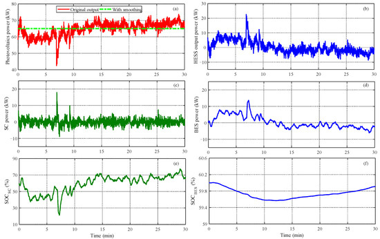
Figure 10.
Photovoltaic power smoothing performance of HESS. (a) Photovoltaic power, (b) HESS power, (c) SC power, (d) BES power, (e) SOC of SC, (f) SOC of BES.
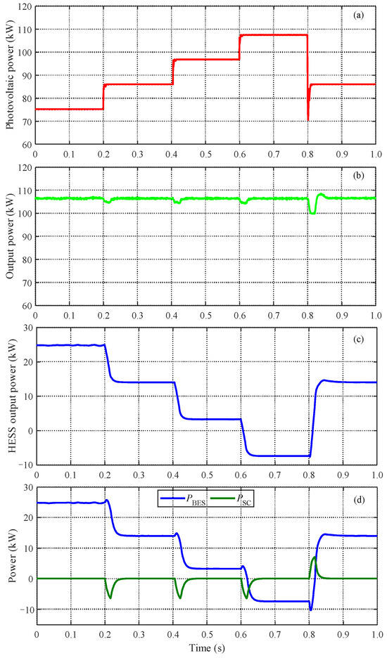
Figure 11.
The smoothing performance of HESS on power output under extreme operational conditions of photovoltaic systems. (a) Photovoltaic power, (b) HESS power, (c) Total power, (d) BES and SC power.
To validate the performance of the proposed supercapacitor-battery hybrid energy storage parallel compensation module in stabilizing renewable energy output power, as illustrated in Figure 10, a smoothing verification was conducted on the power fluctuation of a photovoltaic generation unit over 30 min. Under the control objective of constant output power and the compensation strategy based on low-pass filter decomposition, as shown in Figure 10c,d, the supercapacitor assumed the high-frequency power components of instantaneous photovoltaic power fluctuations, while the battery handled the low-frequency power components of photovoltaic variations. This coordinated operation maintained the output power of the photovoltaic generation unit at a stable level of 65 kW.
As shown in Figure 11a, the simulation of photovoltaic systems under extreme operating conditions with shading is presented. During the time interval from 0.2 s to 0.8 s, a step disturbance in the photovoltaic output power is introduced. The supercapacitor-battery energy storage system is controlled to maintain a constant output power target from the PV. At the moments of 0.2 s, 0.4 s, and 0.6 s, following a 10-kW fluctuation in the photovoltaic output power, as illustrated in Figure 11c, the hybrid energy storage system promptly compensates by delivering 10 kW of power, stabilizing the photovoltaic output at 107 kW. Notably, during the instantaneous change in photovoltaic output power, the supercapacitor effectively compensates for the entire power fluctuation. As depicted in Figure 11d, within the subsequent 30 milliseconds, the battery output is gradually adjusted to the target compensation value, while the supercapacitor output power is progressively restored to zero. Figure 11b illustrates that throughout the entire simulation period, the photovoltaic output remains stable under the power compensation of the hybrid energy storage system, exhibiting only minor fluctuations at the moment of power transition. This validates the effectiveness of the supercapacitor-battery energy storage parallel compensation module in smoothing the output power of renewable energy sources.
5.4. Reverse Power Generation
The load of the oil pumping unit differs from conventional loads in that it converts gravitational potential energy into electrical energy during the downstroke motion and feeds it back into the power supply grid. Due to periodic power consumption and reverse power flow, this process tends to cause sustained voltage fluctuations and short-term surges in the bus voltage. Hybrid energy storage systems can mitigate these issues by compensating for power peaks in the oil pumping unit’s load, thereby reducing the design threshold of power supply capacity in oilfield microgrids and decreasing line losses. Additionally, the energy storage system can absorb the reverse power flow from the oil pumping unit load, alleviating the sustained disturbances caused by periodic reverse power flow on the bus voltage. This enhances the voltage stability of DC microgrids in oilfields with a high proportion of renewable energy sources.
As shown in Figure 12a, during each stroke cycle of the pumping unit load, the load sequentially undergoes power consumption and reverse power generation processes. To mitigate the power impact disturbances on the DC microgrid caused by the peak power consumption and reverse power generation characteristics of the pumping unit load, while reducing the short-term maximum transmission power of the DC microgrid and avoiding power feedback from the pumping unit, a hybrid energy storage system combining supercapacitors and batteries is deployed to enhance the stable operation performance of the DC microgrid.
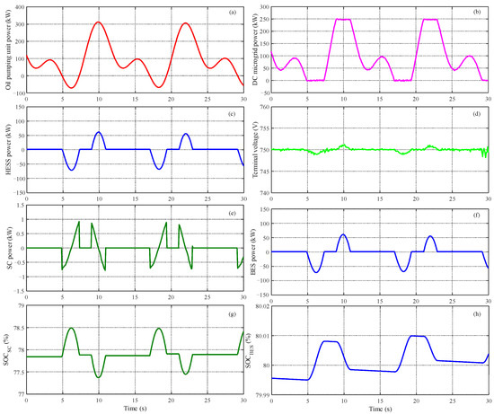
Figure 12.
Compensation performance of HESS under oil pumping unit operation. (a) Oil pumping unit power, (b) DC microgrid power, (c) HESS power; (d) Terminal voltage, (e) Supercapacitor power, (f) Battery power, (g) SOC of supercapacitor, (h) SOC of battery.
In the case-study simulation, as illustrated in Figure 12b,c, when the pumping unit load exceeds 250 kW, the hybrid energy storage system supplies the power deficit. This limits the microgrid’s peak transmission power to within 250 kW. During the reverse power generation phase of the pumping unit load (e.g., 5–7.5 s), the hybrid energy storage absorbs the feedback power and releases it during peak power consumption (e.g., 9–11 s) to achieve energy balance over the operational cycle. As shown in Figure 11d, when the load operates at peak or reverse power generation intervals, the DC bus voltage fluctuation of the oilfield microgrid can be confined within ±1 V under the power compensation of the hybrid energy storage parallel converter, effectively resisting voltage disturbances caused by pumping unit load variations.
Notably, the power variation rate of the pumping unit load is significantly slower than the response time of the supercapacitor. As demonstrated in Figure 12e,f, the power deficit or surplus due to load fluctuations can be primarily managed by the battery to maintain DC bus voltage stability, with minimal power contribution from the supercapacitor. During periodic operation, as shown in Figure 12g,h, the SOC of the supercapacitor remains nearly stable, while the battery SOC exhibits a slight increase. This imbalance can be addressed by adjusting the battery’s charge/discharge schedule to achieve energy equilibrium.
5.5. Pulse Load
To further validate the universality and adaptability of the proposed series-parallel hybrid energy storage compensation scheme combining supercapacitors and batteries, additional performance verification was conducted for pulsed load scenarios, as illustrated in Figure 13. In the case study, pulsed power loads with an amplitude of 100 kW were applied at 0.2 s and 0.6 s, with durations of 100 ms and 200 ms, respectively. As shown in Figure 13b–d, during the operation of pulsed loads, the supercapacitor and battery energy storage systems rapidly released energy to compensate for the abrupt power variations, ensuring stable power transmission on the grid side while mitigating power disturbances caused by load fluctuations in the DC microgrid. The transmission power of the DC microgrid exhibited fluctuations only during the transition phases of supercapacitor and battery power output, subsequently returning to normal operation.
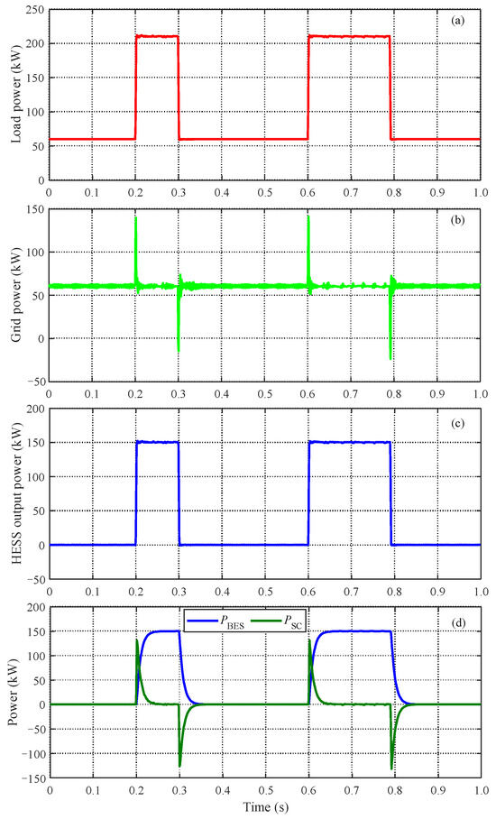
Figure 13.
The compensation performance of HESS under pulse load operation. (a) Pulse load power, (b) Grid power, (c) HESS power, (d) BES and SC power.
5.6. Performance Comparison Between the Proposed Scheme and Existing Schemes
5.6.1. Comparative Analysis of Voltage Compensation Performance
To demonstrate the advantages of the proposed hybrid supercapacitor-battery energy storage series-parallel compensation scheme over conventional technical solutions, a comparative analysis was conducted between the voltage compensation and power regulation performance of the proposed approach and conventional schemes, considering the distinct functionalities of series and parallel compensation modules. As shown in Figure 14, this study’s supercapacitor series compensation approach demonstrates superior performance compared to traditional battery energy storage systems configured in parallel. In the comparative case studies of voltage sag and swell shown in Figure 14a,b, due to the limited power compensation capability of conventional battery energy storage in parallel configuration, significant instantaneous voltage drops were observed in the DC bus voltage during both fault inception and recovery transients. For instance, as depicted in Figure 14a, during the voltage sag fault, the DC bus voltage rapidly dropped to a minimum of 314 V in the initial transient phase before gradually recovering to 750 V. In contrast, the proposed supercapacitor series compensation scheme, functioning as a voltage-type direct compensation method, enables faster and higher-power compensation, effectively confining the instantaneous DC bus voltage fluctuations within ±5%. This approach successfully addresses the transient voltage peak fluctuations caused by the sluggish response of traditional battery systems.
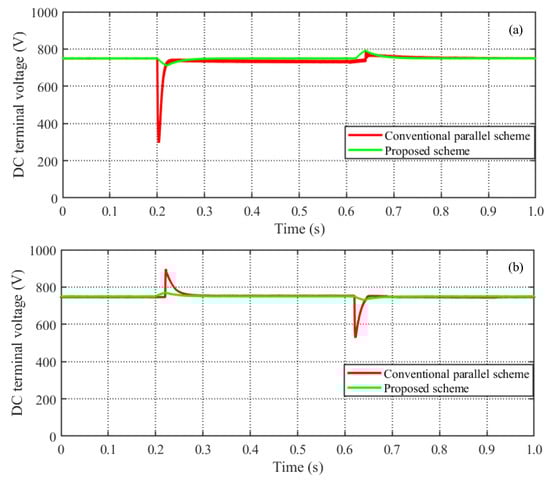
Figure 14.
Performance comparisons between conventional BES parallel compensation and the proposed series compensation scheme. (a) Voltage sag, (b) Voltage swell.
5.6.2. Comparative Analysis of Power Compensation Performance
In terms of the parallel power compensation regulation performance of the supercapacitor-battery hybrid energy storage system, a case study was conducted to compare the proposed power-current dual-loop control scheme, incorporating the current inner-loop model predictive control with the conventional PI control scheme. As illustrated in Figure 15, in response to power regulation commands, the proposed control scheme demonstrates smoother tracking and lower overshoot compared to the traditional PI control. Although the PI control scheme initially exhibits faster incremental power output from the battery, its overall stabilization time is prolonged, primarily due to the extended recovery time of the supercapacitor. Overall, the proposed control scheme achieves the power regulation target more rapidly, demonstrating its effectiveness and superiority.
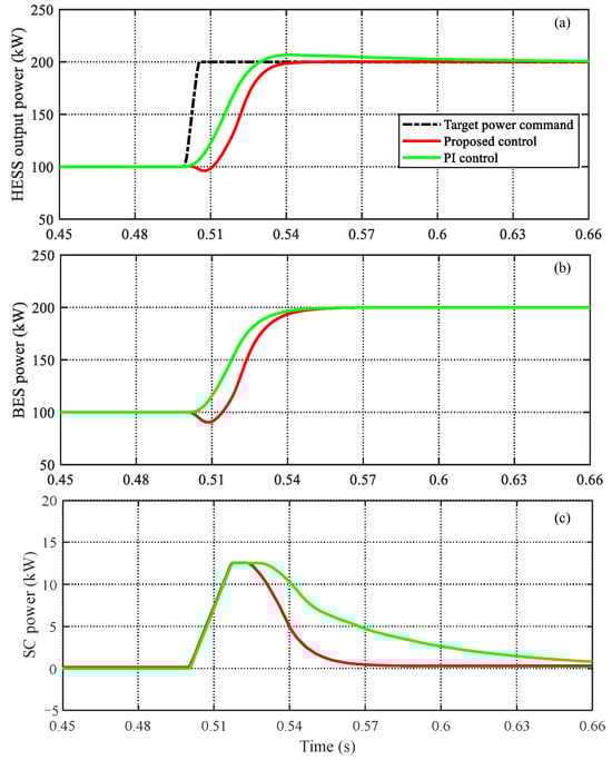
Figure 15.
Performance comparisons between the conventional HESS compensation scheme and the proposed HESS parallel compensation scheme. (a) HESS, (b) BES, (c) SC.
5.6.3. Sensitivity Analysis of Circuit Parameters
Regarding the influence of circuit parameters on the power compensation performance of the supercapacitor-battery hybrid energy storage system, the inductor parameters in the bidirectional buck-boost converter exhibit a certain impact on the output response of the hybrid energy storage under the proposed control scheme, with the inductor parameters playing a dominant role compared to the capacitor parameters. As shown in Figure 16a, as the inductor parameters increase, the response speed of the hybrid energy storage system slightly decreases. This is because larger inductor parameters limit the current change rate of the converter, resulting in a marginal reduction in response speed. In terms of output response amplitude, larger inductor parameters significantly affect the rapid power output of the supercapacitor. Therefore, the inductance in the supercapacitor converter loop should be appropriately reduced during design to achieve higher output power. Overall, within a reasonable design range, the converter inductor parameters have minimal influence on the overall response settling speed and overshoot of the hybrid energy storage system.
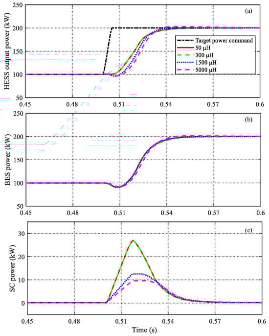
Figure 16.
Comparative analysis of HESS response performance under different inductance parameters for the proposed control scheme. (a) HESS power, (b) BES power, (c) SC power.
6. Conclusions
This paper has investigated a series-parallel hybrid compensation topology for supercapacitor-battery hybrid energy storage and a hybrid energy storage control strategy based on model predictive control. It addresses issues such as smoothing the output power fluctuations of renewable energy in DC microgrids, mitigating voltage sags/swells, and reducing the impact of reverse power generation from oil pumping unit loads. A simulation model of the oilfield DC microgrid was established in MATLAB/Simulink to validate the compensation performance of the hybrid energy storage system, demonstrating the feasibility and superiority of the proposed solution. The overall novelty and contributions can be summarized as follows:
- (1)
- A series-parallel hybrid compensation topology combining supercapacitors and batteries is proposed for oilfield DC microgrids. This topology notably broadens the dynamic voltage compensation range of DC systems. Moreover, it strengthens the fault-ride-through capacity and improves the power supply quality of generation units in microgrids with a high penetration of renewable energy.
- (2)
- An improved hybrid energy storage current inner-loop control strategy based on model predictive control is proposed. This strategy aims to enhance the dynamic response characteristics of the hybrid energy storage system, reduce the discharge rate of the battery, improve the voltage stability of the oilfield DC microgrid, and extend the service life of the energy storage devices.
Overall, the proposed hybrid energy storage system combining supercapacitors and batteries with series-parallel compensation significantly enhances the power supply quality of DC microgrids. It is particularly suitable for scenarios such as oilfield microgrids with high penetration of renewable energy, data centers, and industrial DC microgrids that contain numerous sensitive loads. Admittedly, the hybrid supercapacitor-battery energy storage series-parallel compensation scheme proposed in this paper exhibits certain limitations in the comprehensiveness of its control strategy. It mainly focuses on regulating the system’s output performance and does not sufficiently emphasize the energy management control of the storage system itself. Future research could further integrate energy management control for the storage system to achieve more comprehensive operational control objectives.
Funding
This research was funded by the Natural Science Foundation of Shandong Province, grant number ZR2024QE225.
Data Availability Statement
The original contributions presented in this study are included in the article. Further inquiries can be directed to the author.
Conflicts of Interest
Author Lina Wang was employed by the Technical Inspection Center of Shengli Oilfield Company, SINOPEC. The author declares that the research was conducted in the absence of any commercial or financial relationships that could be construed as a potential conflict of interest.
References
- Shu, H.; Ni, C.; Wang, L.N.; Yan, C.; Sun, D.; Li, W.; Wang, F.; Xu, H.; Sheng, Q. Analysis and description of key technologies of intelligent energy system integrated with source-grid-load-storage in the oil field. Processes 2023, 11, 2169. [Google Scholar] [CrossRef]
- Wangsupphaphol, A.; Phichaisawat, S.; Nik Idris, N.R.; Jusoh, A.; Muhamad, N.D.; Lengkayan, R. A systematic review of energy management systems for battery/supercapacitor electric vehicle applications. Sustainability 2023, 15, 11200. [Google Scholar] [CrossRef]
- Ray, A.; Rajashekara, K. Electrification of offshore oil and gas production: Architectures and power conversion. Energies 2023, 16, 5812. [Google Scholar] [CrossRef]
- Su, K.; Wang, X.; Xie, X. Advanced grid-forming undersea pumped storage to enable 100% renewable offshore oilfield power systems. IEEE Trans. Sustain. Energy 2025, in press. [Google Scholar] [CrossRef]
- Nair, M.G.; Solanki, S.K.; Thakur, T. Development of hybrid energy storage system testbed with instantaneous discharge controller for shunt active filter application. Sustainability 2023, 15, 11247. [Google Scholar] [CrossRef]
- Chen, X.; Chen, Y.; Fu, L.; Zhang, Z.; Tang, M.; Feng, J.; Jiang, S.; Lei, Y.; Zhang, D.; Shen, B. Photovoltaic-driven liquid air energy storage system for combined cooling, heating and power towards zero-energy buildings. Energy Convers. Manag. 2024, 300, 117959. [Google Scholar] [CrossRef]
- Alonso, A.M.; Costa, D.; Messagie, M.; Coosemans, T. Techno-economic assessment on hybrid energy storage systems comprising hydrogen and batteries: A case study in Belgium. Int. J. Hydrogen Energy 2024, 52, 1124–1135. [Google Scholar] [CrossRef]
- Guven, A.F.; Abdelaziz, A.Y.; Samy, M.M.; Barakat, S. Optimizing energy dynamics: A comprehensive analysis of hybrid energy storage systems integrating battery banks and supercapacitors. Energy Convers. Manag. 2024, 312, 118560. [Google Scholar] [CrossRef]
- Reveles-Miranda, M.; Ramirez-Rivera, V.; Pacheco-Catalán, D. Hybrid energy storage: Features, applications, and ancillary benefits. Renew. Sustain. Energy Rev. 2024, 192, 114196. [Google Scholar] [CrossRef]
- Wu, X.; Li, S.; Gan, S.; Hou, C. An adaptive energy optimization method of hybrid battery- supercapacitor storage system for uncertain demand. Energies 2022, 15, 1765. [Google Scholar] [CrossRef]
- Garcia, F.S.; Ferreira, A.A.; Pomilio, J.A. Control strategy for battery-ultracapacitor hybrid energy storage system. In Proceedings of the 24th IEEE Annual Applied Power Electronics Conference and Exposition, Washington, DC, USA, 15–19 February 2009; pp. 826–832. [Google Scholar]
- Jia, Y.; Tian, J.; Ren, C.; Wang, J.; Li, Y. DC microgrid hybrid energy storage system and control based on converter cascade. J. Sol. Energy 2020, 41, 273–280. [Google Scholar]
- Inoue, S.; Akagi, H. A bi-directional dc/dc converter for an energy storage system. In Proceedings of the 22nd IEEE Annual Applied Power Electronics Conference and Exposition, Anaheim, CA, USA, 25 February–1 March 2007; pp. 761–767. [Google Scholar]
- Lin, W.; Guo, X.; Huang, C. Bidirectional large-variable-ratio DC-DC switching converter with improved single-cycle control strategy. Chin. J. Electr. Eng. 2012, 32, 31–37. [Google Scholar]
- Raikar, S.B.; Saha, A.; Vittal, K.P. Frequency filtering in ultracapacitor-battery energy storage system in electric vehicles. In Proceedings of the 2022 IEEE North Karnataka Subsection Flagship International Conference, Vijaypur, India, 20–21 November 2022; pp. 1–7. [Google Scholar]
- Ma, L.; Xie, L.; Ye, L.; Lu, P.; Wang, K. Wind power fluctuation smoothing strategy based on hybrid energy storage two-layer planning model. Grid Technol. 2022, 46, 1016–1026. [Google Scholar]
- Liao, K.; Xu, Y.; Yin, M.; Chen, Z. A virtual filter approach for wind energy conversion systems for mitigating power system frequency fluctuations. IEEE Trans. Sustain. Energy 2019, 11, 1268–1277. [Google Scholar] [CrossRef]
- Nikoobakht, A.; Aghaei, J.; Shafie-khah, M.; Catalão, J.P.S. Allocation of fast-acting energy storage systems in transmission grids with high renewable generation. IEEE Trans. Sustain. Energy 2019, 11, 1728–1738. [Google Scholar] [CrossRef]
- Sun, Y.; Tang, X.; Sun, X.; Jia, D.; Wang, P.; Zhang, G. Research on coordinated control strategy of multi-type energy storage based on MPC-HHT. Chin. J. Electr. Eng. 2018, 38, 2580–2588. [Google Scholar]
- Xie, L.; Zheng, H.; Wei, C.; Huo, S. A coordinated control strategy for photovoltaic hybrid energy storage with compensation of prediction error and fluctuation smoothing. Power Syst. Autom. 2021, 45, 130–138. [Google Scholar]
- Ma, W.; Wang, W.; Wu, X.; Hu, R.; Yan, L. Optimal scheduling strategy of hybrid energy storage system for smoothing photovoltaic grid-connected power fluctuation. Power Syst. Autom. 2019, 43, 58–66. [Google Scholar]
- Liu, J.; Zhang, L. Strategy design of hybrid energy storage system for smoothing wind power fluctuations. Energies 2016, 9, 991. [Google Scholar] [CrossRef]
- Nair, U.R.; Costa-Castelló, R. A model predictive control-based energy management scheme for hybrid storage system in islanded microgrids. IEEE Access 2020, 8, 97809–97822. [Google Scholar] [CrossRef]
- Zheng, Z.; Chen, X.; Hu, W.; Wang, Y.; Zong, Y.; Huang, C. Dual model predictive controlled hybrid energy storage system for naval DC microgrids. IEEE Trans. Transp. Electrif. 2022, 9, 156–168. [Google Scholar] [CrossRef]
- Li, Z.; Wang, X.; Zhang, S.; Shi, M. On-line identification parameters of lithium-ion battery equivalent model based on recursive least square method. Shandong Electr. Power 2021, 48, 1–6. [Google Scholar]
- Sun, K.; Yu, J.; Jiang, W.; Yu, B.; Li, Z.; Hu, P. SOC feedback control strategy of hybrid energy storage system for suppressing intermittent loads. In Proceedings of the 2021 IEEE Sustainable Power and Energy Conference, Nanjing, China, 23–25 December 2021; pp. 1249–1255. [Google Scholar]
- Abdurraqeeb, A.M.; Al-Shamma’a, A.A.; Alkuhayli, A.; Alharbi, M.; Farh, H.M.H.; Addoweesh, K.E. Enhancing performance of supercapacitor based hybrid energy storage system using RST controller in an islanded DC microgrid. J. Energy Storage 2025, 113, 115522. [Google Scholar] [CrossRef]
Disclaimer/Publisher’s Note: The statements, opinions and data contained in all publications are solely those of the individual author(s) and contributor(s) and not of MDPI and/or the editor(s). MDPI and/or the editor(s) disclaim responsibility for any injury to people or property resulting from any ideas, methods, instructions or products referred to in the content. |
© 2025 by the author. Licensee MDPI, Basel, Switzerland. This article is an open access article distributed under the terms and conditions of the Creative Commons Attribution (CC BY) license (https://creativecommons.org/licenses/by/4.0/).