Abstract
The combustion behavior and thermal performance of industrial-scale borax pentahydrate (Na2B4O7·5H2O) melting furnaces remain underexplored despite their critical role in boric oxide (B2O3) production, a key input for high-performance manufacturing. This study addressed this gap by employing three-dimensional computational fluid dynamics (CFD) simulations to model two operational natural gas-fired furnaces with distinct burner configurations (four-burner and six-burner systems). The analysis focused on optimizing burner placement, specifically, the axial distance and inclination angle, to enhance thermal uniformity and reduce refractory wall damage caused by aggressive high-temperature borate corrosion. A comprehensive parametric study of twelve burner configurations revealed that tilting the burners at 5–10° significantly improved temperature uniformity while reducing peak wall temperatures and mitigating localized hot spots. The optimal design, incorporating a 10° burner angle and a staggered burner arrangement (Case 11), attained a melt pool temperature of 1831.3 K and a charging average wall temperature of 1812.0 K. These values represent essential benchmarks for maximizing furnace efficiency and operational stability. The modified designs for the four- and six-burner systems led to improved temperature distributions and a notable reduction in maximum wall temperatures, directly contributing to longer maintenance intervals and improved refractory durability. The findings of this study confirm that minor geometrical and angular adjustments in burner placement can yield significant performance gains. The validated CFD approach and proposed design modifications offer a scalable, low-cost strategy for improving combustion efficiency and furnace lifespan in borax processing facilities.
1. Introduction
The drying process of borax pentahydrate (Na2B4O7·5H2O) leads to obtaining anhydrous borax (Na2B4O7), which is a source material of boric oxide (B2O3) [1]. Boric oxide can be used to manufacture several types of borosilicate glass, including heat and chemical-resistant glasses, illumination glasses, optical lenses, medical and cosmetic containers, hollow microspheres and glass beads [2]. Industrial natural gas melting furnaces are used for the drying process of borax pentahydrate [3,4,5]. Since borax pentahydrate is a highly corrosive material, the walls of the furnaces are easily damaged during the process, which leads to short maintenance time intervals for the furnaces [6,7]. These natural gas melting furnaces may have different numbers of burners to complete the combustion process [8,9].
There are relatively few investigations in the literature that employ computational fluid dynamics (CFD) modeling to simulate the combustion process in the melting of borax pentahydrate. The studies conducted for conventional melting furnaces typically aim to understand and optimize various aspects of the combustion process, including heat transfer, fluid flow, chemical reactions, and emissions. By employing CFD techniques, researchers can simulate and analyze the complex interactions occurring during combustion, providing valuable insights for improving process efficiency, reducing environmental impacts, and ensuring product quality in manufacturing.
Leicher [10] investigated flameless oxidation melting furnaces to decrease the amount of NOx emissions from a glass melting furnace. They developed a GlasFLOX burner using both experimental and CFD studies. They concluded that this burner decreased NOx emissions by about 50%. In another study, Jeong et al. [11] conducted CFD modeling of coal gasification in a gasifier to investigate the effect of the coal size on the gasification performance. The authors solved three-dimensional Navier–Stokes equations with the Eulerian–Lagrangian method under steady-state conditions. They also used user defined functions to solve char gasification reactions. The CFD model fairly agreed with the experimental data in terms of species mole fractions and exit temperature.
Yangaz et al. [12] examined the effects of industrial gas burner modifications on emissions efficiency. The authors analyzed the effects of preheating and EGR on conventional type burners after geometric modifications of both the furnace design and the burners. The energy use in glass production technologies was studied by Springer and Hasanbeigi [13]. The researchers included energy efficiency mechanisms, challenges, emission reduction techniques and other benefits of each technology. One of the main research projects regarding flameless oxidation was published by Wünning [14]. The authors presented NOx reducing techniques. The results showed that the burners used in flameless oxidation mode are reliable and well established.
Sun et al. [15] investigated an industrial gas burner integrating air swirl and an inverse diffusion flame to enhance combustion stability and efficiency. Using CFD simulations, they analyzed turbulent flow, flame structures, and burner configurations, revealing that swirl-induced recirculation zones play a crucial role in stabilizing combustion. Their findings indicate that optimizing the number and inclination angle of fuel nozzles can significantly reduce NO emissions, with 16 nozzles at a 60° inclination achieving a 28.5% reduction. In another study, Milani and Wünning [16] investigated flameless oxidation in radiant tubes in a steel heat treatment process. They reviewed design criteria for radiant tubes with a new design for larger industrial furnaces.
Biyikoglu and Yeksan [6] designed and manufactured a prototype furnace to produce anhydrous borax. They also carried out a set of experiments to produce anhydrous borax. They used powder atomization units during the study to overcome the difficulties in the production stage. The authors reported that anhydrous borax has the following constituents with mass percentages of 30.38% Na2O and 68.24% B2O3. They also conducted experiments on the product using titration and XRD. The results showed that the products have nearly the same composition and can be regarded as anhydrous borax.
Khan et al. [17] studied colemanite and borax pentahydrate as alternative sources for CaO and Na2O during the production of SLS glass. The incorporation of B2O3 with the utilization of colemanite decreased the melting temperature of SLS from 1650 °C to 1528 °C. The use of both colemanite and borax pentahydrate further reduced the melting temperature of SLS to 1072 °C. Thus, the researchers showed that energy consumption and, consequently, CO2 emissions could be decreased during the production of glass using colemanite and borax pentahydrate as alternative sources.
Şahin et al. [18] investigated the production of anhydrous puffed borax from borax pentahydrate in a batch calcinator. The borax pentahydrate was covered with a CaO layer to obtain a higher melting point. The researchers investigated the effect of the CaO layer on the calcination process. The results showed that anhydrous borax could be successfully obtained by calcination of borax pentahydrate particles covered with CaO in 50-, 20- and 5-min time intervals at a temperature range of 300, 400 and 500 °C, respectively.
The characteristics of the combustion products of boron were investigated by Liu et al. [19]. The particle size of the combustion products was analyzed by a laser particle size analyzer. The authors conducted DSC, X-ray photoelectron spectroscopy and X-ray diffraction experiments to analyze the samples’ compositions. They found that some components in the primary combustion products were agglomerated, while some elements were dispersed. Therefore, the combustion completeness of the primary combustion products is low. The authors concluded that secondary combustion process control is crucial to improve the combustion performance of boron. Daurer et al. [20] compared the electric boosting and bubbling methods for an industrial melting furnace using a CFD study. The authors suggested the use of both electrodes and nozzles for melting furnaces. Zhang et al. [21] simulated the waste-to-energy of gasifying and direct melting furnaces. The authors demonstrated that the established CFD-DEM model can be used as a tool for the optimization of operating conditions and scaled-up designs for future prototype waste-to-energy gasifying and direct melting furnaces.
Although several studies have been conducted on the modeling of high-temperature industrial furnaces, particularly in glass melting applications, the existing literature lacks focused investigations on borax pentahydrate melting furnaces using CFD. To the best of the authors’ knowledge, this study presents the first CFD-based analysis tailored explicitly to the combustion characteristics and thermal performance of borax pentahydrate melting furnaces fueled by natural gas. The present work contributes to the literature by modeling two operational furnaces and performing a detailed numerical analysis to understand their combustion behavior. A key objective was to optimize burner positioning (in terms of distance and angle) to enhance combustion efficiency and achieve a more uniform temperature distribution, both of which are critical for stable furnace operation and prolonged refractory life. Unlike prior studies that often relied on simplified geometries or generalized combustion models, this study employed detailed burner geometry, a non-premixed combustion model, and the Discrete Ordinates radiation model to ensure higher fidelity in representing the furnace environment. One of the critical industrial challenges addressed in this study is the frequent structural damage to furnace walls caused by the chemically aggressive nature of borax pentahydrate at elevated temperatures. These failures result in frequent shutdowns, requiring maintenance and reducing overall production efficiency. By providing a validated CFD model and an optimization framework for burner placement, this study offers actionable design insights that can mitigate material degradation and extend furnace operating periods. Additionally, this study introduces the design and CFD analysis of a larger-capacity furnace, aiming to provide a scalable and more durable solution for industrial use. The comparative results between the existing and newly designed furnaces highlight the impact of optimized thermal management on operational reliability and productivity. The findings of this study thus serve as a guideline for industrial practitioners involved in the design, operation, and maintenance of borax pentahydrate furnaces.
2. Materials and Methods
2.1. Furnace Description
Two different melting furnaces, both designed to process borax pentahydrate materials, were investigated in this study. Both furnaces utilized a consistent feed rate of 650 kg/h of raw material. The raw materials were introduced into the system using automated feed mechanisms to ensure uniformity in material input and thermal distribution. The temperature within each furnace was maintained at a steady state to optimize the melting process and to minimize energy consumption. The temperature within the furnaces was kept at a precise set point, which varied according to the specific requirements of each product.
In the simulation of the combustion and flow behavior within industrial-scale borax pentahydrate furnaces the flow was assumed to be steady-state and turbulent. Heat transfer was primarily governed by radiation and combustion processes. The furnace walls were modeled with a no-slip boundary condition. These assumptions align with established practices in CFD modeling of industrial furnaces.
2.2. Numerical Setup and Solvers
The simulations were based on the solutions of the Reynolds-Averaged Navier–Stokes (RANS) equations for mass, momentum, energy, and species transport. CFD techniques, coupled with combustion models, were employed to accurately represent the combustion processes occurring within the furnace. The combustion process in the borax pentahydrate melting furnace was modeled using a non-premixed combustion approach employing the PDF-based species transport formulation [22,23]. This selection was because in industrial natural gas burners, the fuel and oxidizer enter the combustion chamber separately and mix primarily during combustion. Since no significant premixing occurs before ignition, a non-premixed combustion model accurately represents the actual physical and chemical behavior within the furnace. Other combustion models, such as partially premixed combustion and detailed chemical kinetics, were also considered. However, a partially premixed model assumes a degree of premixing between fuel and air before combustion, which does not align with the operating conditions of the investigated industrial burners. Additionally, while detailed chemical kinetics models provide highly accurate reaction simulations, they introduce significant computational overhead due to the inclusion of numerous chemical species and reaction mechanisms. Given the large scale nature of the furnace and the primary focus on burner optimization and temperature distribution, a non-premixed combustion model was selected to provide an optimal balance between computational efficiency and predictive accuracy.
Heat transfer mechanisms, including convection, conduction, and radiation, were comprehensively modeled. Radiative heat transfer was treated using the Discrete Ordinates (DO) radiation model, which is well-suited for high-temperature, participating media typical of industrial furnace environments. Wall emissivity is assumed to be constant, and radiative heat fluxes are resolved along discrete angular directions. To accurately capture turbulent flow behavior, particularly within the boundary layer, the Realizable k-ε turbulence model with standard wall functions was employed [24,25]. The finite volume method (FVM) was employed for spatial discretization due to its conservation properties and suitability for complex geometries [26,27]. A second-order upwind scheme was utilized to discretize the convective terms, providing an optimal balance between accuracy and numerical stability by considering the flow direction during the interpolation of cell face values. This approach effectively reduces numerical diffusion and enhances precision when capturing flow and thermal gradients. The Coupled scheme was employed for pressure–velocity coupling in the CFD simulations. This scheme simultaneously solves the momentum and pressure-based continuity equations, providing robust and efficient convergence, which is particularly beneficial for complex flow scenarios such as those present in industrial natural gas burners.
Given that the simulations were conducted under steady-state conditions, temporal discretization was not required. These discretization strategies align with established practices in CFD analyses of combustion systems, ensuring the reliability and accuracy of the simulation outcomes. The CFD models were simulated to investigate the combustion characteristics, flow dynamics, and thermal behavior of the borax pentahydrate melting furnace.
2.3. Furnace Modeling
The melting furnaces are equipped with natural gas burning systems featuring two different configurations: one furnace contains six burners (B-6) and the other contains four burners (K-4). The capacity of each burner in the B-6 furnaces is 300 kW, while in the K-4 furnaces, it is 600 kW. Intake air, preheated to approximately 90 °C using flue gas, is supplied to the burners. This air, along with the natural gas, is regulated at the furnace entrance through a distributed control system using proportional valves. Operational strategies for the burners vary based on their position relative to the raw material input. Burners situated proximally to the raw material operate at maximum capacity. Those located in the middle of the furnace operate at approximately 60% capacity, while burners near the chimney and flow opening are reduced to about 20% capacity. During the production of anhydrous borax, the temperature within the melting furnace is meticulously maintained within a range of 900–950 °C.
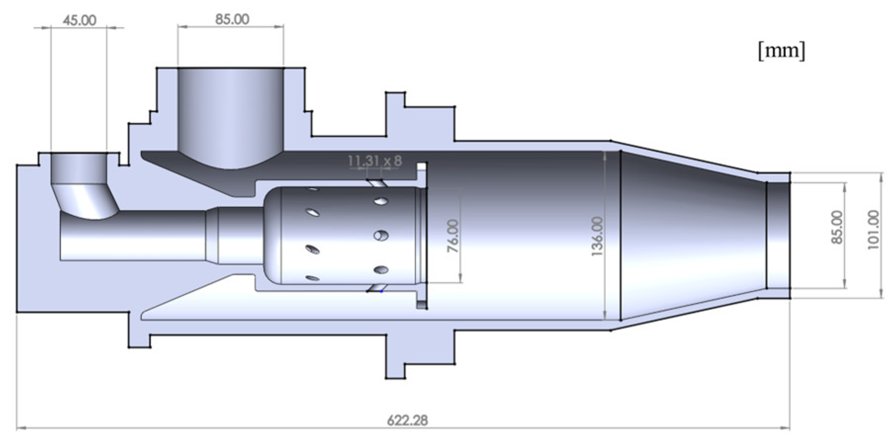
The investigation detailed in this study aimed to analyze the thermal behavior and flow characteristics in melting furnaces. The research methodology employed the CFD method to comprehensively understand the complex phenomena occurring within these industrial systems. The numerical simulations were performed using ANSYS Fluent® 2020R2 commercial software [26]. A comprehensive 3D CAD model, comprising both the furnace and the burner, was developed. This model was constructed based on technical drawings, which ensured a high level of precision in the experimental conditions. The computational domain includes the detailed geometry of the industrial natural gas burners and the borax pentahydrate melting furnaces. The main dimensions of the furnaces are as follows: the B-6 furnace measures 2300 × 2400 × 4800 mm, while the K-4 furnace has dimensions of 3400 × 2200 × 4700 mm. These dimensions define the overall structure of the furnaces and are critical for accurately capturing the flow and combustion characteristics within the CFD model. The burner geometry is presented in Figure 1, illustrating the essential features such as the nozzle arrangement, air–fuel mixing chamber, and flame stabilization zone. The burner model includes all relevant structural components to ensure an accurate representation of the combustion process. The placement of burners within the furnace was carefully modeled to reflect real operating conditions and allow for optimization studies.
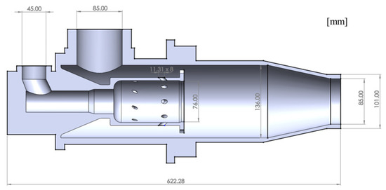
Figure 1.
Schematic representation of the burner geometry.
2.4. Boundary Conditions
After the generation of the 3D CAD model of the furnace system, the boundary conditions for the CFD model were identified from experimental data, furnace measurements, wall temperatures, gas flow rates and air flow rates and subsequently defined in the model. The geometry and operating parameters were input into the CFD model to simulate the heat transfer and fluid flow phenomena.
The fuel mixture used in the models was composed of molar fractions as follows: methane (CH4) at 0.965, carbon dioxide (CO2) at 0.003, butane (C4H10) at 0.001, propane (C3H8) at 0.001, ethane (C2H6) at 0.017, and nitrogen (N2) at 0.013. The boundary conditions for each burner in the melting furnace are specified as follows:
Burner 1: The fuel flow rate is set at 31.63 m3/h, with an air flow rate of 366.8 m3/h. The fuel pressure is maintained at 4.88 mbar and the air pressure at 6.49 mbar.
Burner 2: The fuel flow rate is 65.10 m3/h, accompanied by an air flow rate of 563.7 m3/h. The fuel pressure is maintained at 20.48 mbar and the air pressure at 15.49 mbar.
Burner 3: The fuel flow rate is set at 48.01 m3/h, with an air flow rate of 243.7 m3/h. The fuel pressure is maintained at 11.31 mbar and the air pressure at 2.88 mbar.
Burner 4: The fuel flow rate is set at 52.10 m3/h, with an air flow rate of 452.1 m3/h. The fuel pressure is maintained at 13.22 mbar and the air pressure at 10.1 mbar.
The boundary conditions used in the CFD simulations were derived directly from experimentally measured parameters of the operating industrial furnaces. To ensure stability and accuracy, each simulation was run for 2000 iterations.
2.5. Meshing Strategy and Validation
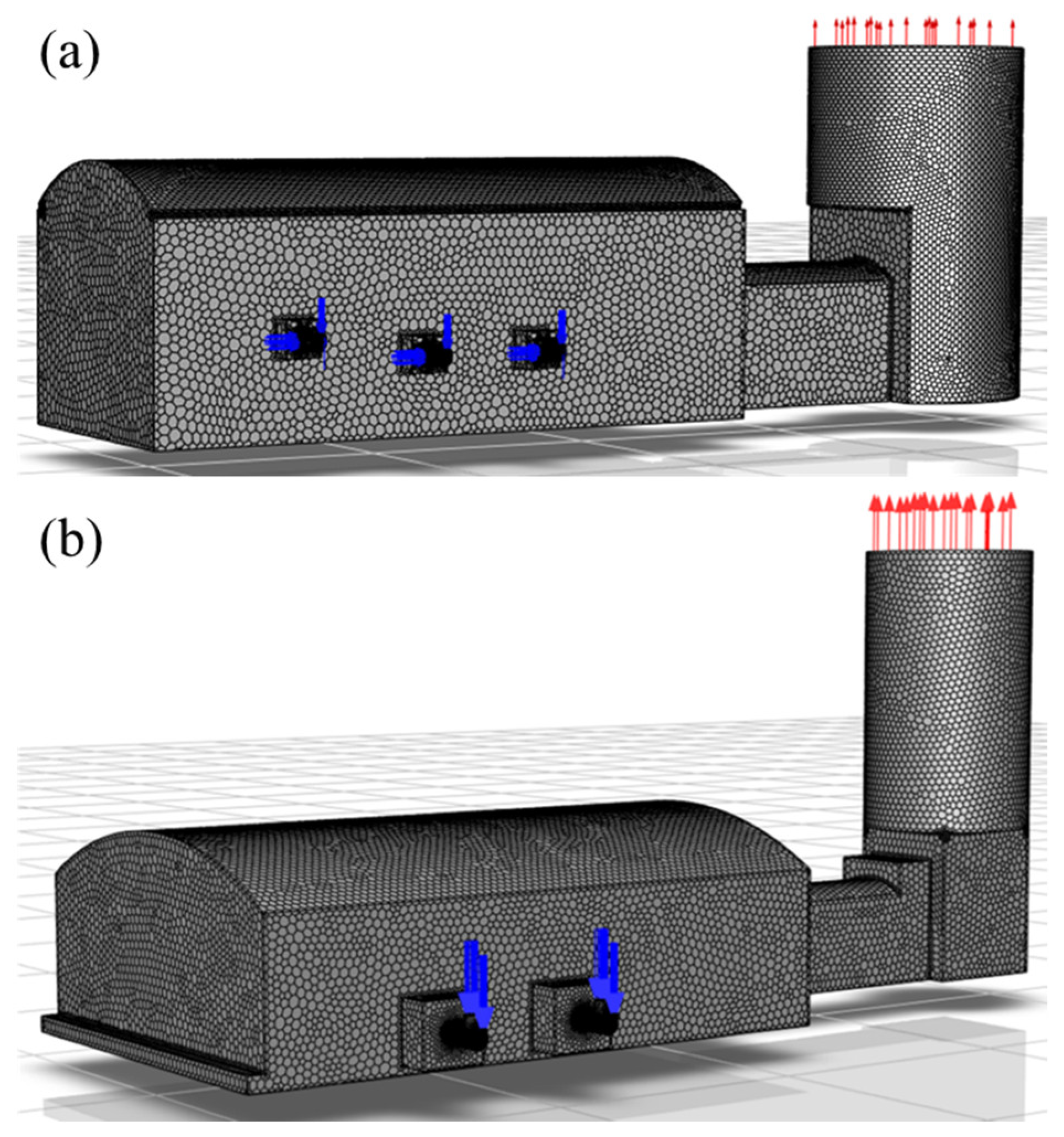
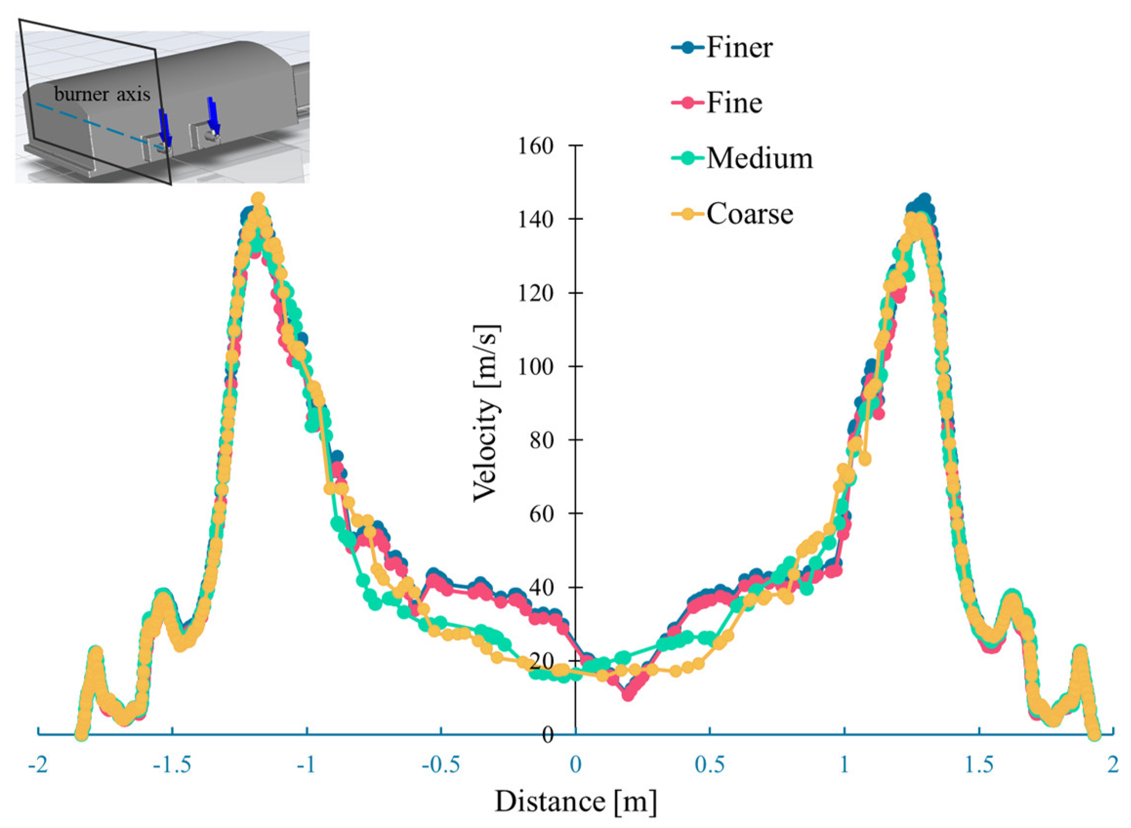
A mesh structure consisting of polyhedral elements was established to ensure an optimal balance between solution time and accuracy. To achieve the most suitable mesh configuration for the simulations, smaller meshing was applied in critical regions, improving the accuracy of the results, as shown in Figure 2. A mesh independence study was conducted to validate the selected mesh configuration. Various mesh sizes were systematically tested, categorized as coarse, medium, fine, and finer, to assess their impact on the solution accuracy. The total number of elements varied for each mesh size, with the coarse mesh containing 4,386,670 elements, the medium mesh consisting of 6,019,513 elements, the fine mesh incorporating 7,398,678 elements, and the finer mesh reaching 9,431,473 elements. Figure 3 shows the velocity profiles along the burner axis for four different mesh resolutions. The velocity distribution was chosen as the primary parameter for this assessment due to its critical role in capturing flow field characteristics, particularly in reactive flow regions [28]. The results demonstrate that, beyond the fine mesh, further refinement yields negligible changes in the velocity field, indicating numerical convergence. Specifically, the velocity profiles for the fine and finer meshes are nearly indistinguishable, whereas the coarse and medium meshes exhibit noticeable deviations, particularly around the center region. This convergence confirms that the solution is independent of the mesh size at the fine level. Therefore, the fine mesh was selected for all subsequent simulations, balancing accuracy with computational efficiency. The quality of the fine mesh was assessed based on element quality and skewness metrics. The element quality values ranged from a minimum of 4.859 × 10⁻⁴ to a maximum of 1, with an average of 0.836 and a standard deviation of 0.0961. The skewness values indicated good mesh quality, with a minimum of 3.0088 × 10⁻⁷, a maximum of 0.99951, an average of 0.23063, and a standard deviation of 0.12151. These values confirm that the mesh maintains an acceptable element distribution with low skewness, ensuring numerical stability and accuracy. Based on these findings, the fine mesh was selected for the CFD simulations as it provides a suitable balance between precision and computational efficiency.

Figure 2.
The grid structure of (a) B-6 furnace and (b) K-4 furnace.
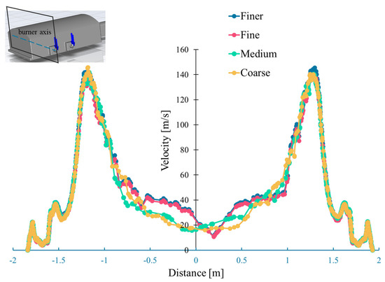
Figure 3.
Velocity values through the burner axis for different mesh sizes.
Temperature measurements were performed at several key locations on the furnace using a calibrated infrared thermometer during steady-state operation for the baseline configuration to validate the CFD model. The measured surface temperatures were 911 °C, 821 °C, 760 °C, 694 °C, and 700 °C. The CFD model predicted temperatures of 974.7 °C, 853.8 °C, 775.2 °C, 728.7 °C, and 763.2 °C at the same locations, respectively. The average absolute deviation between the measured and simulated values was approximately 6.8%, which is within the acceptable range for industrial-scale combustion simulations. The slightly higher values in the CFD results are attributed to the idealized boundary assumptions. Nevertheless, the close agreement between simulation and measurement confirms the reliability of the model for subsequent optimization studies.
2.6. Optimization
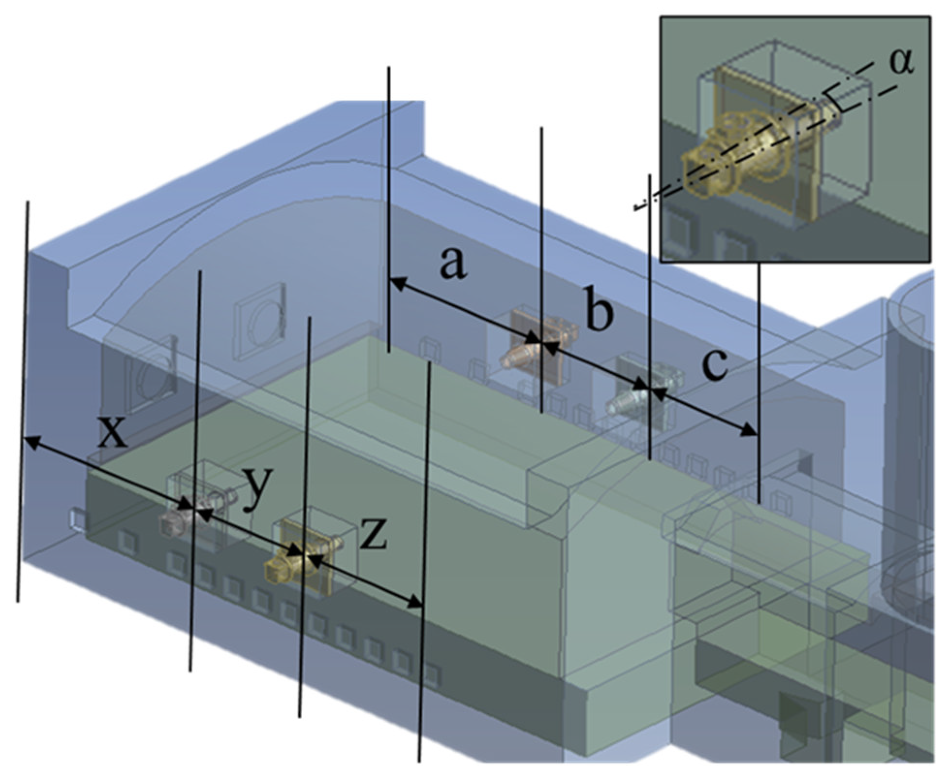
After baseline simulations, parametric optimization was conducted by systematically modifying the burner placement and inclination angle across a series of configurations. The goal was to improve the thermal and combustion performance of the furnace. Twelve cases were evaluated. Each scenario was evaluated to determine its influence on the temperature distribution and flow characteristics. The spatial definitions and parameter locations associated with these configurations are illustrated in Figure 4, which serves as the reference schematic for the geometric variables listed in Table 1 and Table 2. The operating parameters of the furnaces were carefully documented and used to define the simulation inputs. As shown in Table 1, two burner configurations were analyzed: a four-burner system and a six-burner system. The baseline geometric dimensions of the furnace domain were standardized as follows: x = 1000 mm, y = 400 mm, z = 400 mm, a = 800 mm, b = 400 mm, and c = 400 mm. These dimensions were maintained to ensure consistency and comparability across all cases. The baseline configuration, Case 1, was selected to represent the current industrial operation, serving as the reference case against which the subsequent scenarios were compared.

Figure 4.
Definition of parameters for various scenarios.

Table 1.
The design parameters for various scenarios.
Table 2.
Parameter values of the various cases.
Table 2 summarizes the parametric values across the twelve parametric scenarios. These include variations in burner attack angle and location, all of which are key parameters influencing internal flow fields, flame impingement behavior, and thermal load distribution. The simulation results were then analyzed in terms of flame structure, temperature distribution, flow velocity profiles, and wall temperature data. Case-by-case comparisons were made to evaluate how each configuration affected operational efficiency and material durability, especially regarding the critical issue of refractory damage caused by non-uniform heating and hot spots.
A comprehensive analysis was conducted to measure the relative impacts of these parameters. From this extensive pool of designs, the optimal configuration was selected based on its ability to achieve the most effective temperature distribution within the predefined design constraints.
3. Results and Discussion
In this section, the detailed findings from the numerical simulations are presented and discussed. The CFD models of two industrial-scale borax pentahydrate melting furnaces were developed and simulated to closely replicate real-world operational conditions. These simulations were constructed using boundary conditions directly derived from actual factory data. A total of twelve burner configuration scenarios were simulated, with systematic variation in burner position and inclination angle. These parametric variations were designed to investigate their impact on combustion efficiency, temperature distribution, and thermal loading on furnace walls. The optimization was driven by two primary objectives:
- Maximization of temperature uniformity across the furnace volume, aiming for consistent heat distribution to minimize localized thermal stress and enhance process control.
- Minimization of excessive wall heating, particularly at the side and charging walls, to prevent refractory degradation and improve furnace longevity.
3.1. Parametric Analysis of Thermal Performance and Velocity Distribution
The temperature uniformity was quantified using an area-weighted uniformity index, calculated from temperature gradients across the furnace walls. Values close to one indicate highly uniform temperature distributions. Wall overheating was evaluated using the maximum surface temperatures recorded at each wall (side, charging, and pool). Additional constraints were enforced to ensure complete combustion (evidenced by near-zero O2 at the outlet) and to prevent flame impingement on critical surfaces. The parametric study varied input conditions such as burner angle and burner position across 12 cases.
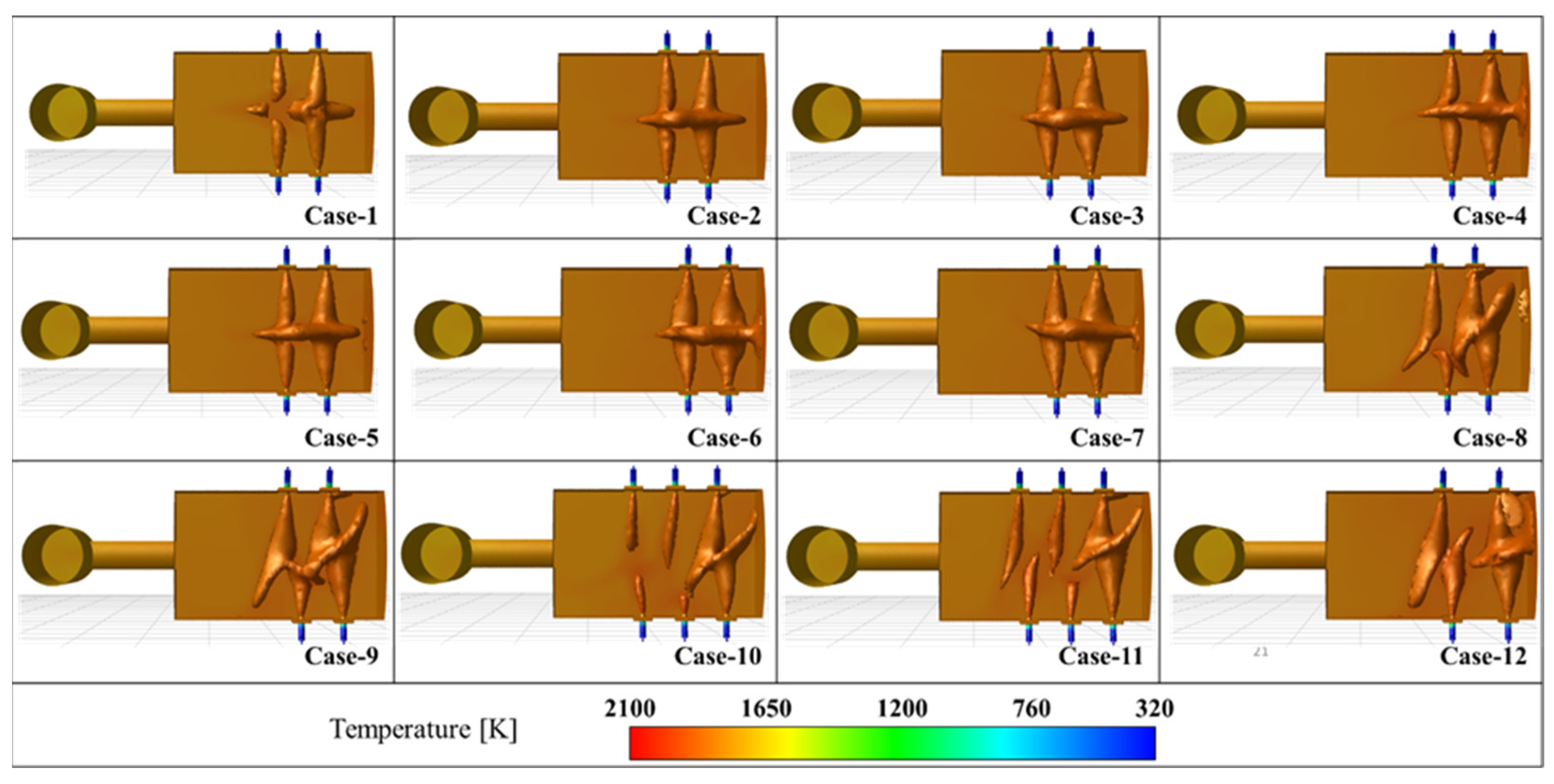
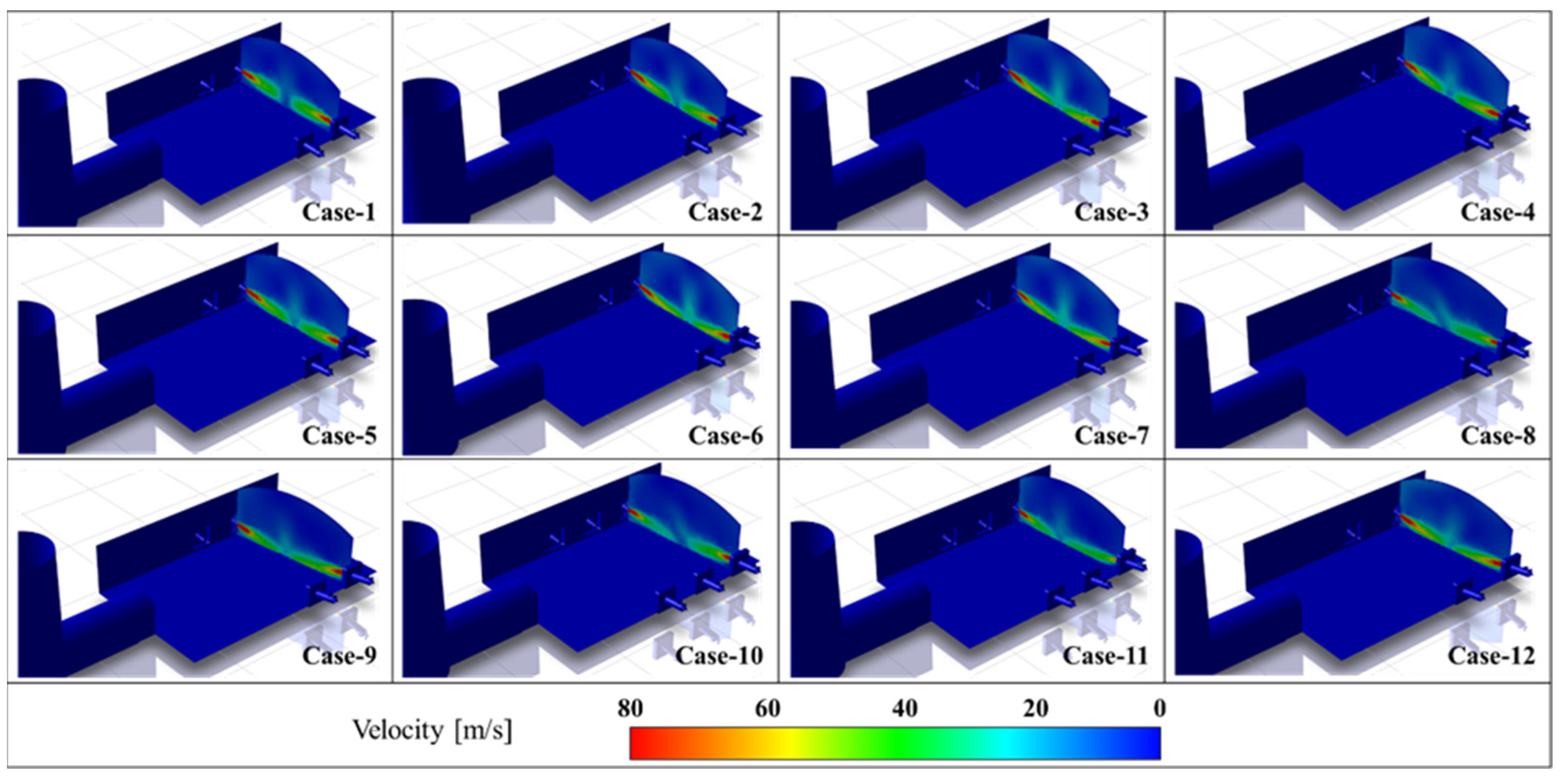
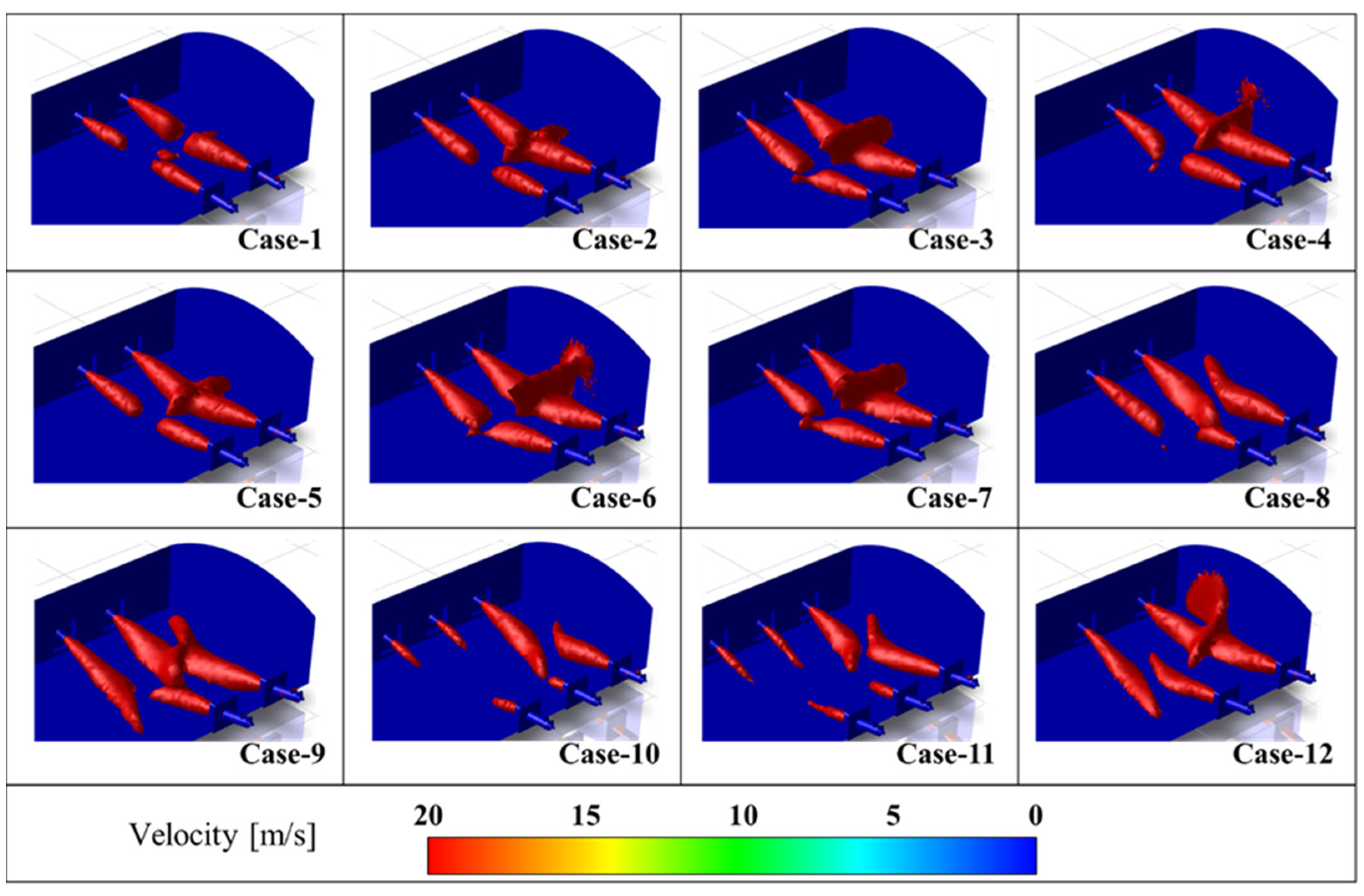
As can be understood from above, the baseline of the furnace is considered in terms of comparison with the results for Case 1. Velocity iso-surface, temperature distribution, velocity distribution and wall temperatures are given for all the cases. The figures provide comprehensive insights into various aspects of furnace operation and design. Figure 5 presents a detailed overview of the temperature distribution with iso-surfaces across different cases, offering information on the heat distribution within the furnace. Figure 6 zooms in on the temperature distribution, specifically at the furnace melt pool, providing critical data for melting furnaces. Figure 7 focuses on the velocity distribution along the burner axis, shedding light on flow patterns influenced by burner positioning. Lastly, Figure 8 shows the velocity iso-surfaces across cases, aiding in the visualization of flow patterns and potential areas of turbulence within the furnace.
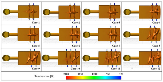
Figure 5.
Temperature distribution of the cases.
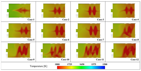
Figure 6.
The temperature distribution at the melt pool of the furnace across different cases.
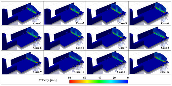
Figure 7.
The velocity distribution along the burner axis.

Figure 8.
The velocity iso-surfaces across different cases.
The impact of burner angle variation was evaluated as part of the optimization study, specifically in Cases 1 through 3 and 4 through 7, where angles of 0°, 5°, and 10° were applied across different spatial configurations. The objective was to assess how altering the burner’s tilt relative to the horizontal axis influences the flame trajectory, wall interactions, and overall thermal field distribution. The results indicate that a burner angle of 0° (Case 1) led to a more axial and concentrated flame path, causing localized high temperatures on the opposite furnace wall. This effect slightly reduced the overall temperature uniformity and increased the wall thermal loading. Increasing the angle to 5° (Cases 2, 4, 5, 8, and 10) resulted in a noticeable improvement in flame spread and distribution along the central furnace axis. The more diffused flame shape enhanced convective heat transfer and reduced peak wall temperatures. Uniformity indices in these cases ranged from 0.99640 to 0.99777, showing better homogenization of the temperature field.
Further increasing the angle to 10° (Cases 3, 6, 7, 9, 11, and 12) led to additional improvements in flame dispersion, particularly in longer furnaces, promoting more even heating at the pool and side walls. Case 12 (10° angle) yielded the highest average temperature at the charging wall (1836 K) and the highest maximum pool temperature (1848.4 K), indicating more efficient heat utilization. However, this configuration also presented the lowest temperature uniformity index (0.99614), suggesting increased temperature gradients due to enhanced directional flow. Overall, the analysis showed that burner angles of 5–10° strike a balance between effective flame spreading and thermal uniformity. A flat (0°) burner configuration leads to focused heating zones and should be avoided in long-duration industrial operations due to potential refractory damage. These outcomes confirm the critical role of angular configuration in optimizing combustion characteristics and guide future furnace design modifications.
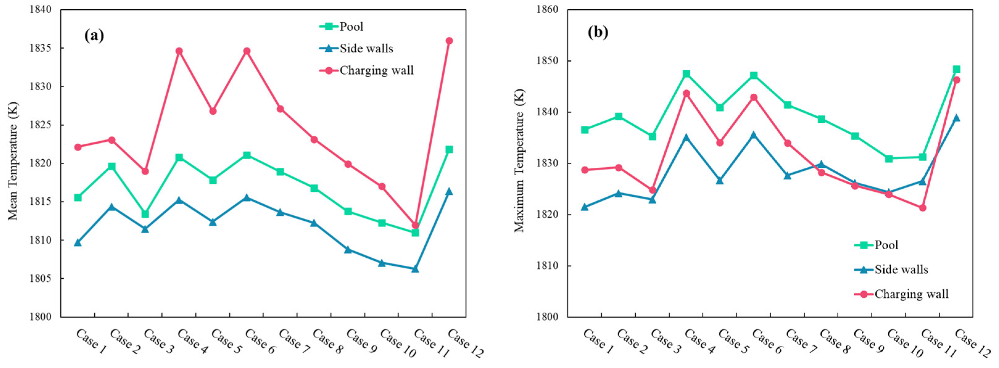
Figure 9 illustrates the mean and maximum temperature distributions across the pool, side walls, and charging wall for twelve different simulation cases. The thermal behavior of these regions offers essential insight into the heat transfer characteristics and localized thermal loading within the furnace.
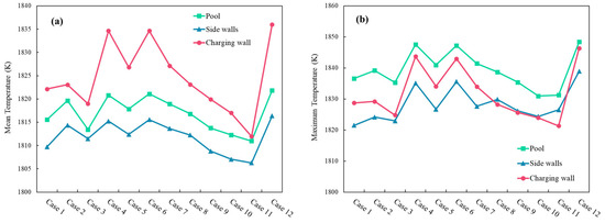
Figure 9.
(a) Mean temperature distributions across different regions, (b) Maximum local temperature distributions across different regions.
In Figure 9a, the charging wall consistently exhibits the highest mean temperatures across most cases, indicating a higher thermal input or lower heat dissipation compared to the pool and side walls. Notably, Cases 4 and 6 show pronounced peaks in the charging wall temperature, suggesting altered flow in those scenarios. Case 11 considerably decreases the temperature of the charging wall. Figure 9b shows a similar trend in the maximum temperature distribution. The pool region experiences the highest maximum temperatures in the majority of cases, peaking prominently in Cases 4 and 6. This suggests that localized hot spots may be forming within the pool, possibly due to turbulent stagnation zones or uneven thermal mixing. The maximum temperatures in the charging wall also follow a correlated pattern with their respective mean values, reinforcing the thermal dominance of this surface. Interestingly, despite having the lowest mean values, the side walls occasionally show elevated maximum temperatures (Cases 6 and 12), indicating possible transient or localized thermal spikes. In Case 11, the thermal load at the charging wall was decreased. Case 12 reached the peak mean temperature of 1836.0 K, with a maximum temperature of 1846.3 K, suggesting intensified combustion near the charging wall. A noticeable dip in Cases 9–11 aligns with reduced combustion intensity, with Case 11 showing the lowest mean charging wall temperature at 1812.0 K. The highest mean temperature (1821.9 K) occurred in Case 12. The maximum pool temperature followed a similar pattern, with 1848.4 K in Case 12 and 1831.3 K in Case 11.
3.2. Emissions
Understanding the emission characteristics of borax pentahydrate melting furnaces is critical for evaluating combustion efficiency, environmental compliance, and operational safety. The mole fractions of key species, namely carbon monoxide (CO), CO2, unburned methane (CH4), and residual oxygen (O2), were analyzed to assess the effects of burner position and inclination angle on combustion completeness. These species are indicative of combustion quality: high CO and CH4 levels suggest incomplete combustion, while elevated CO2 levels and near-zero O2 indicate efficient fuel oxidation.
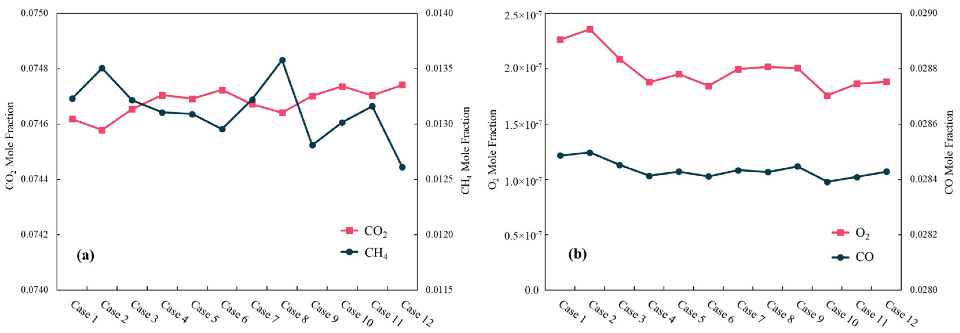
Figure 10a presents the mole fraction variations of CO2 and CH4 across different cases. The trends indicate a relatively stable CO2 fraction with minor fluctuations, whereas the CH4 mole fraction shows more pronounced variations, with obvious peaking in certain cases. These trends highlight the impact of burner configurations and operating conditions on combustion efficiency. Higher CH4 levels suggest incomplete combustion, while stable CO2 levels indicate consistent oxidation reactions. The observed variations necessitate further optimization of burner positioning and air–fuel ratios to enhance combustion completeness.
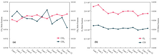
Figure 10.
(a) CO2 and CH4 mole fractions, (b) O2 and CO mole fractions across cases.
Figure 10b illustrates the variations in O2 and CO mole fractions under different conditions. The O2 mole fraction remains relatively low, which is expected in a well-optimized combustion process. The CO mole fraction, although slightly varying, remains within an acceptable range, indicating efficient combustion with minimal CO emissions. However, cases with lower O2 levels correlate with increased CO production, which suggests localized oxygen depletion leading to incomplete oxidation. These findings reinforce the necessity of fine-tuning burner configurations to maintain optimal excess air levels for minimizing CO emissions and ensuring complete fuel oxidation.
3.3. Optimal Burner Arrangements
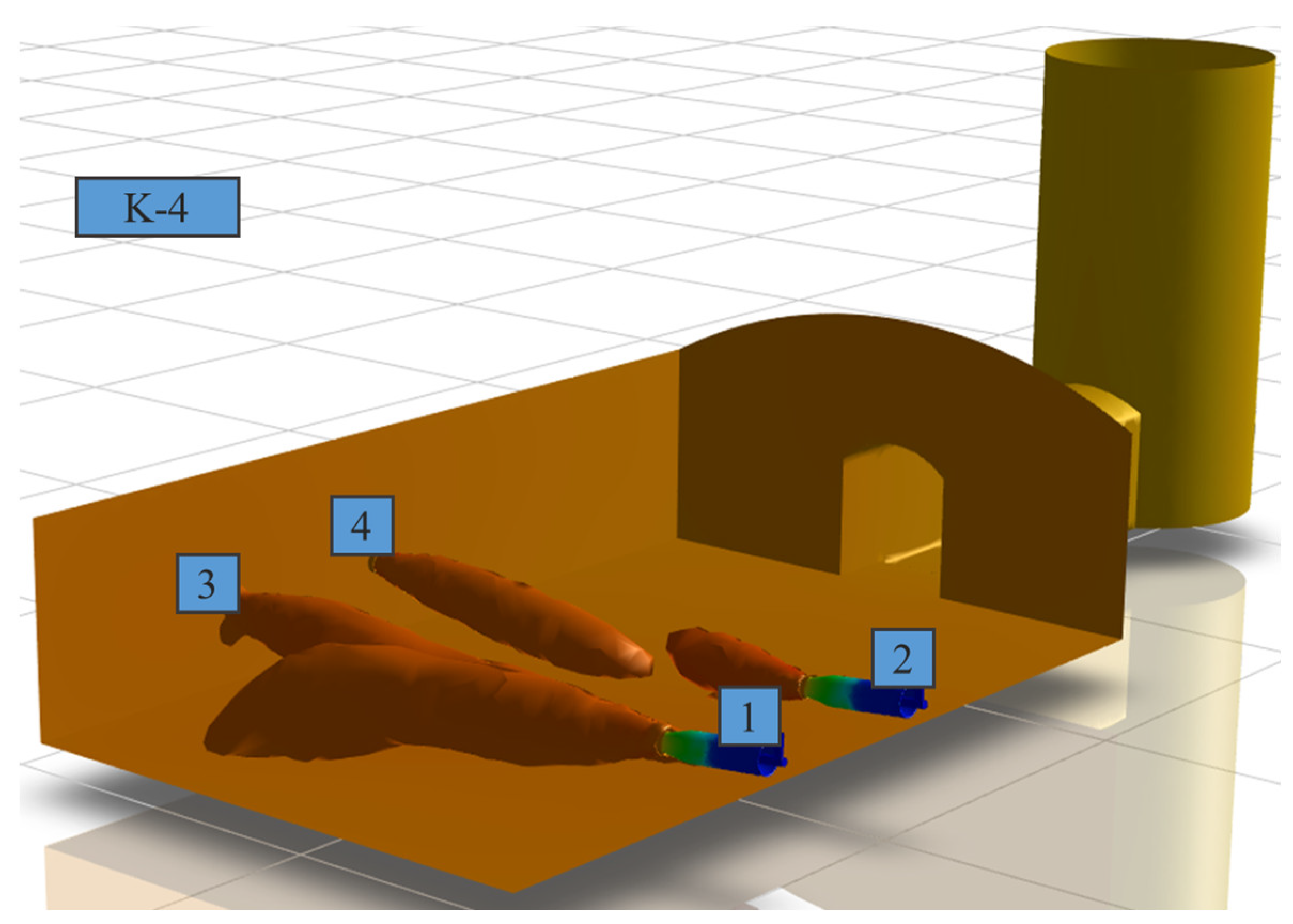
As part of the scope of the minor revision of the furnace, the optimal placement and angles of burners for designs with four and six burners are presented in Figure 11 and Figure 12. These figures illustrate the final proposed burner placements for the optimized designs of four-burner and six-burner borax pentahydrate melting furnaces. These figures are a culmination of the CFD-based parametric optimization study, representing the configurations that delivered the best balance between temperature uniformity, peak wall temperatures, flame impingement avoidance, and combustion efficiency. Figure 11 corresponds to Case 9, which demonstrated superior thermal behavior among the four-burner scenarios. All burners are tilted at 10°, which was found to promote effective flame spreading and minimize concentrated heat zones. The burners are asymmetrically positioned relative to the central furnace axis. Each burner is slightly shifted to avoid alignment with each other and the furnace symmetry plane, thereby disrupting axial symmetry in their flame paths, a strategy that enhances mixing and prevents hot spots. This configuration generated a mean melt pool temperature of 1813.8 K, with maximum pool and wall temperatures well-distributed, avoiding local overheating. The flow field analysis showed smoother recirculation zones, facilitating better heat transfer. The CO and unburned CH4 mole fractions remained within acceptable limits, confirming complete combustion and oxygen utilization.
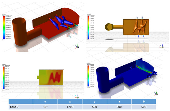
Figure 11.
Proposed burner placement and design with four burners, Case 9.

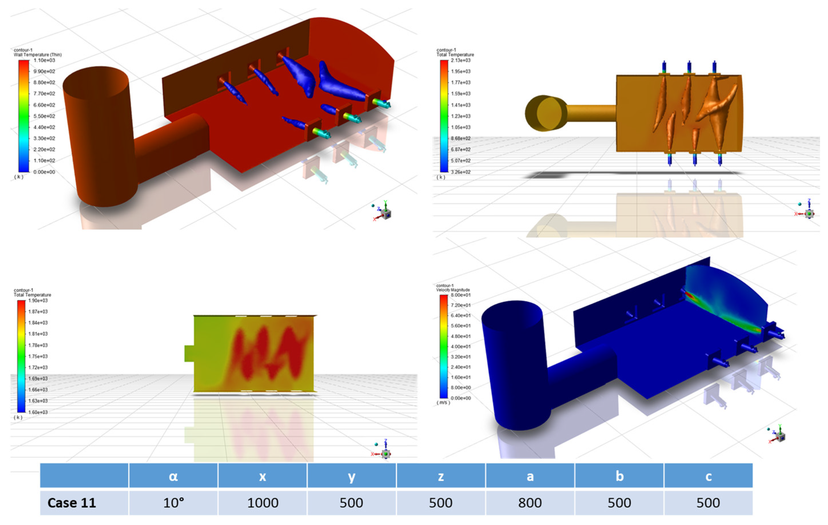
Figure 12.
Proposed burner placement and design with six burners, Case 11.
The Case 11 configuration, which provided optimal results among the six-burner furnace designs, is shown in Figure 12. A uniform 10° tilt is applied across all six burners, promoting directional flame development while avoiding direct impingement on refractory walls. The burners are arranged in a staggered layout along the furnace length and width. The maximum melt pool temperature is 1831.3 K, indicating enhanced energy delivery to the charge material. The charging wall showed a mean temperature of 1821.4 K, significantly lower than in some other cases (e.g., Case 4 or 6), suggesting improved thermal load management and reduced refractory stress. The temperature uniformity index was maintained at a high level (≥0.997), even with increased energy density, which is critical for scaling up furnace capacity without sacrificing stability.
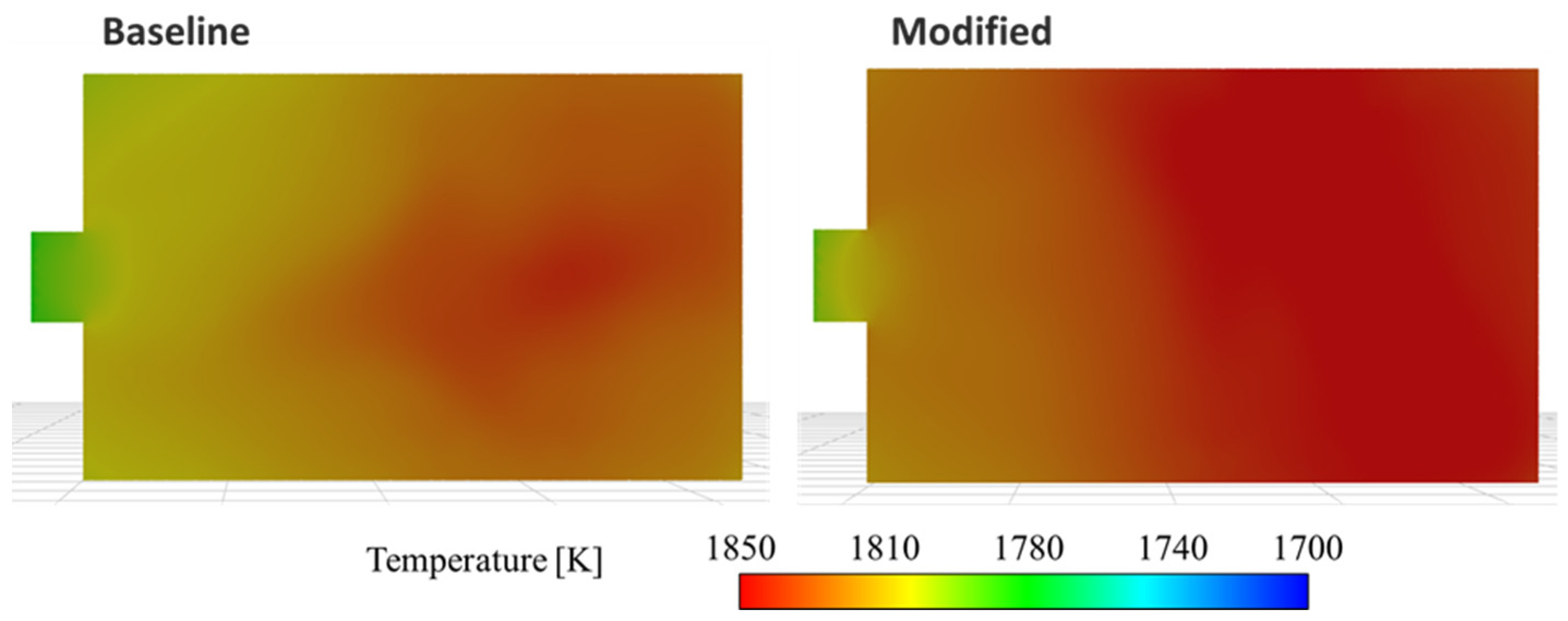
Based on these findings, the adjustments were made using the suggested optimization parameters—specifically, the burner tilt angle and the distances at which the burners are positioned. These changes took into account the constraints imposed by furnace design, such as the placement of natural gas lines and burner bricks at the operational sites. Figure 13 has been updated to illustrate the optimal burner positions aligned with the limits of furnace design. The burners have been positioned at a 5° angle. Burner number one has been shifted 150 mm toward the flue side. Burner number two has been shifted 100 mm toward the charging side. Burner number three has been shifted 50 mm toward the flue side. Burner number four has been shifted 100 mm toward the flue side. The results for the K-4 furnace, according to the specified requirements and limits and based on the optimal burner angle and positions, are comparatively presented in Figure 14, Figure 15 and Figure 16.

Figure 13.
Modified furnace design for K-4 furnace.
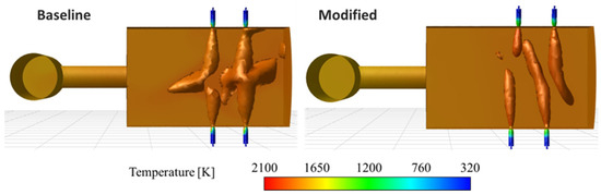
Figure 14.
Comparison of the modified furnace design with the baseline design for the K-4 furnace.

Figure 15.
The temperature distribution at the melt pool of the baseline and modified furnaces.

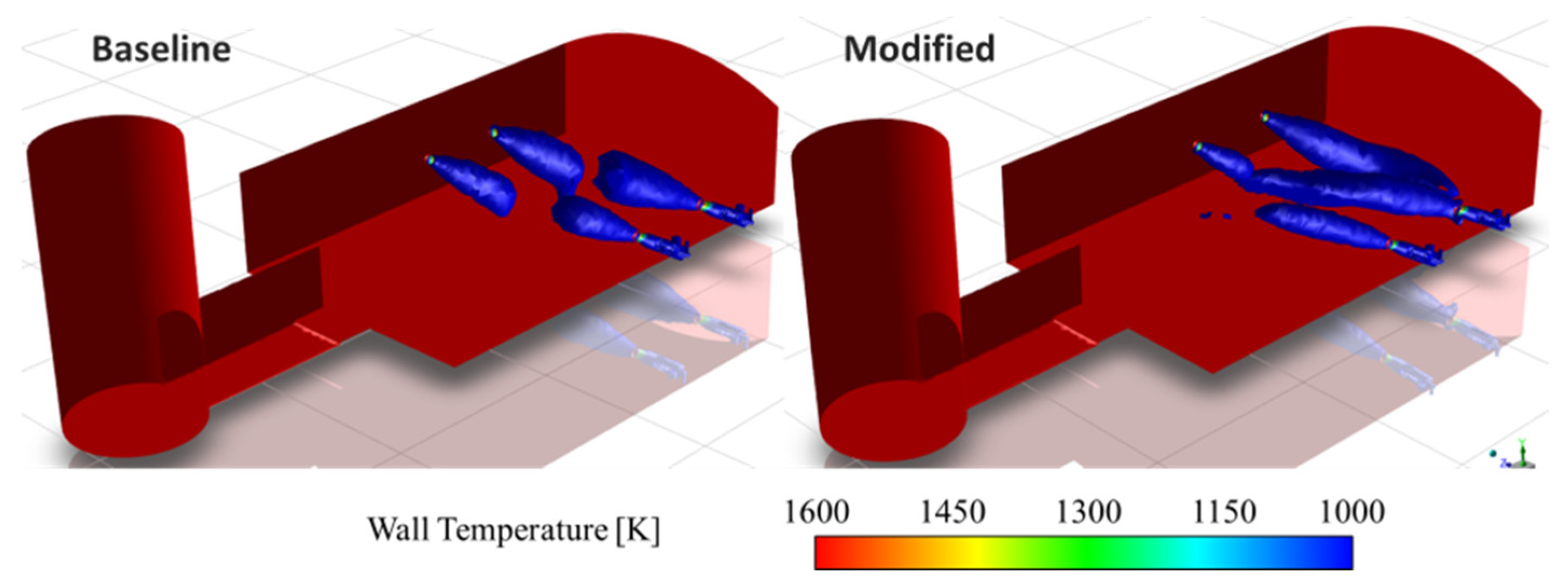
Figure 16.
The wall temperature distribution and velocity iso-surfaces of the baseline and modified furnaces.
The modifications in burner angles and positioning demonstrate a significant impact on the temperature distributions within the furnaces. The strategic realignment and capacity adjustments of the burners facilitate a more uniform temperature profile, which is critical for optimizing the efficiency of the process.
4. Conclusions
This study presents a detailed CFD-based investigation into the combustion characteristics and thermal behavior of natural gas-fired borax pentahydrate melting furnaces, with a specific focus on optimizing the burner configuration for improved performance and extended operational life. By modeling two industrial-scale furnaces with distinct burner arrangements (the K-4 and B-6 systems), this research addresses a critical industrial challenge: non-uniform heating and refractory degradation due to high-temperature borate corrosion.
Twelve parametric configurations were evaluated to assess the influence of the burner angle and spatial positioning on the temperature distribution, flame structure, flow velocity, and wall heat load. The simulations demonstrated that burner inclination angles of 5° to 10° significantly enhanced thermal uniformity and reduced the maximum wall temperatures. Among these, Case 11 (10° burner angle) achieved the most favorable results, with a maximum melt pool temperature of 1831.3 K, mean charging wall temperature of 1812.0 K, and uniformity index of 0.99721, indicating an excellent temperature distribution.
The optimization study revealed that improper burner alignment (e.g., the 0° angle in Case 1) leads to axial flame trajectories, concentrated heat loads, and localized thermal stress on the furnace walls. Conversely, tilted burner configurations promote broader flame dispersion and more uniform energy delivery. The modified furnace designs, validated under real operational constraints, demonstrated enhanced performance, including lower refractory exposure to thermal peaks and reduced CH4 and CO mole fractions, indicating improved combustion completeness.
From a practical perspective, these findings offer actionable design guidelines for furnace manufacturers and operators. By adjusting the burner orientation and spatial placement within design limitations, it is possible to extend maintenance intervals, increase process efficiency, and improve overall furnace longevity without substantial structural changes. The CFD modeling approach also establishes a robust framework for future scaling and retrofitting of borax processing furnaces.
In conclusion, this study bridges a crucial gap in high-temperature industrial furnace modeling for borax pentahydrate applications and provides a validated methodology for optimizing combustion systems. Future research should explore transient simulations, detailed chemical kinetics, and alternative fuel compositions to further enhance the predictive accuracy and environmental sustainability of these systems. The information obtained from this study can help reduce the maintenance interval of borax pentahydrate furnaces. Since the burner position and attack angle are optimized, flame damage to the furnace walls will be reduced, which will allow longer maintenance intervals.
Author Contributions
Conceptualization, R.S. and B.T.; methodology, M.R.O.; software, R.S.; validation, R.S. and B.T.; formal analysis, M.R.O.; investigation, B.T. and İ.S.; resources, B.T.; data curation, R.S.; writing—original draft preparation, R.S. and M.R.O.; writing—review and editing, B.T.; visualization, R.S.; project administration, B.T.; funding acquisition, B.T. All authors have read and agreed to the published version of the manuscript.
Funding
This research was funded by MIATT Inc. grant number STB83132.
Data Availability Statement
The original contributions presented in this study are included in the article. Further inquiries can be directed to the corresponding author.
Acknowledgments
The authors acknowledge that the support for this work is provided by MIATT Inc. under STB83132.
Conflicts of Interest
The authors declare that they have no known competing financial interests or personal relationships that could have appeared to influence the work reported in this paper.
References
- Kocakuşak, S.; Köroglu, H.J.; Gözmen, T.; Savaşcı, O.T.; Tolun, R. Drying of Wet Borax Pentahydrate by Microwave Heating. Ind. Eng. Chem. Res. 1996, 35, 159–163. [Google Scholar] [CrossRef]
- Hamed, H.; Eldiasty, M.; Seyedi-Sahebari, S.-M.; Abou-Ziki, J.D. Applications, Materials, and Fabrication of Micro Glass Parts and Devices: An Overview. Mater. Today 2023, 66, 194–220. [Google Scholar] [CrossRef]
- García, A.M.; López, Y.; Amell, A.A. Numerical Analysis of Oxygen Enrichment in a Self-Recuperative Radiant-Tube Burner. Int. J. Heat. Mass. Transf. 2024, 223, 125154. [Google Scholar] [CrossRef]
- Juan de Dios Rivera, J.R. Emissions of Industrial Sources Converted to Natural Gas. Energy Sources 2001, 23, 115–126. [Google Scholar] [CrossRef]
- Filho, E.M.; de Paulo Nicolau, V.; Seman, L.O.; Possamai, T.S. Heat Transfer Simulation in an Industrial Furnace Firing Natural Gas and Pure Oxygen for Production of Ceramic Frits. J. Braz. Soc. Mech. Sci. Eng. 2023, 45, 150. [Google Scholar] [CrossRef]
- Bıyıkoğlu, A.; Yeksan, E. Production of Anhydrous Borax from Borax Pentahydrate. Int. J. Hydrogen Energy 2008, 33, 7103–7109. [Google Scholar] [CrossRef]
- Şahin, Ö.; Bulutcu, A.N. Dehydration Behaviour of Borax Pentahydrate to Anhydrous Borax by Multi-Stage Heating in a Fluidized. Turk. J. Chem. 2002, 26, 89–96. [Google Scholar]
- Rezazadeh, N.; Hosseinzadeh, H.; Wu, B. Effect of Burners Configuration on Performance of Heat Treatment Furnaces. Int. J. Heat. Mass. Transf. 2019, 136, 799–807. [Google Scholar] [CrossRef]
- Matyukhin, V.I.; Yaroshenko, Y.G.; Matyukhina, A.V.; Dudko, V.A.; Punenkov, S.E. Natural-Gas Heating of Cupola Furnaces for More Energy-Efficient Iron Production. Steel Transl. 2017, 47, 528–533. [Google Scholar] [CrossRef]
- Leicher, J. Flameless Oxidation as a Means to Reduce NOx Emissions in Glass Melting Furnaces. Int. J. Thermodyn. 2013, 16, 55–61. [Google Scholar] [CrossRef]
- Jeong, H.J.; Seo, D.K.; Hwang, J. CFD Modeling for Coal Size Effect on Coal Gasification in a Two-Stage Commercial Entrained-Bed Gasifier with an Improved Char Gasification Model. Appl. Energy 2014, 123, 29–36. [Google Scholar] [CrossRef]
- Yangaz, M.U.; Çiftçioğlu, G.A.; Kadırgan, M.A.N. Comparison of Conventional and Modified Burners in Performance with Different Fuels Using a Linear and a Non-Linear Eddy-Viscosity Turbulence Model. J. Appl. Fluid. Mech. 2019, 12, 2069–2081. [Google Scholar] [CrossRef]
- Springer, C.; Hasanbeigi, A. Emerging Energy Efficiency and Carbon Dioxide Emissions-Reduction Technologies for the Glass Industry; U.S. Department of Energy: Berkeley, CA, USA, 2017.
- Wünning, J. Flameless Oxidation to Reduce Thermal No-Formation. Prog. Energy Combust. Sci. 1997, 23, 81–94. [Google Scholar] [CrossRef]
- Sun, M.; Shao, Y.; Gong, Y.; Xu, C.; Song, T.; Lu, P.; Agarwal, R.K. Numerical Investigation of Flow and Flame Structures in an Industrial Swirling Inverse Diffusion Methane/Air Burner. Fire 2024, 7, 237. [Google Scholar] [CrossRef]
- Milani, A.; Wünning, J.G. New Regenerative Burner for Flameless Oxidation in Radiant Tubes. In Proceedings of the 32nd Meeting on Combustion, Napoli, Italy, 26–28 April 2009; pp. 1–6. [Google Scholar]
- Khan, S.; Allu, A.R.; Gaddam, A.; Fernandes, H.R.; Dutta, S.; Kongar, P.S.; Tarafder, A.; Ferreira, J.M.F.; Annapurna, K. Use of Colemanite and Borax Penta-Hydrate in Soda Lime Silicate Glass Melting—A Strategy to Reduce Energy Consumption and Improve Glass Properties. Ceram. Int. 2022, 48, 1181–1190. [Google Scholar] [CrossRef]
- Şahin, Ö.; Genli, N.; Özdemir, M. A New Method for Producing Anhydrous Puffed Borax. Chem. Eng. Process. Process Intensif. 2005, 44, 1–6. [Google Scholar] [CrossRef]
- Liu, J.; Liang, D.; Xiao, J.; Chen, B.; Zhang, Y.; Zhou, J.; Cen, K. Composition and Characteristics of Primary Combustion Products of Boron-Based Propellants. Combust. Explos. Shock. Waves 2017, 53, 55–64. [Google Scholar] [CrossRef]
- Daurer, G.; Raič, J.; Demuth, M.; Gaber, C.; Hochenauer, C. Detailed Comparison of Physical Fining Methods in an Industrial Glass Melting Furnace Using Coupled CFD Simulations. Appl. Therm. Eng. 2023, 232, 121022. [Google Scholar] [CrossRef]
- Zhang, H.; Okuyama, K.; Higuchi, S.; Soon, G.; Lisak, G.; Law, A.W.-K. CFD-DEM Simulations of Municipal Solid Waste Gasification in a Pilot-Scale Direct-Melting Furnace. Waste Manag. 2023, 162, 43–54. [Google Scholar] [CrossRef]
- Jones, W.P.; Prasetyo, Y. Probability Density Function Modeling of Premixed Turbulent Opposed Jet Flames. Symp. (Int.) Combust. 1996, 26, 275–282. [Google Scholar] [CrossRef]
- Kim, I.S.; Mastorakos, E. Simulations of Turbulent Non-Premixed Counterflow Flames with First-Order Conditional Moment Closure. Flow. Turbul. Combust. Former. Appl. Sci. Res. 2006, 76, 133–162. [Google Scholar] [CrossRef]
- Cellek, M.S.; Pınarbaşı, A.; Coskun, G.; Demir, U. The Impact of Turbulence and Combustion Models on Flames and Emissions in a Low Swirl Burner. Fuel 2023, 343, 127905. [Google Scholar] [CrossRef]
- Şener, R.; Demir, M.E. Heat Transfer and Flow Characteristics of a Novel Turbulator Design in Heat Exchanger: Experimental and Numerical Analysis. Proc. Inst. Mech. Eng. Part. A J. Power Energy 2024, 238, 1228–1237. [Google Scholar] [CrossRef]
- ANSYS Inc. ANSYS Fluent Software: CFD Simulation 2020; ANSYS Inc.: Canonsburg, PA, USA, 2020. [Google Scholar]
- Versteeg, H.K.; Malalasekera, W. An Introduction to Computational Fluid Dynamics: The Finite Volume Method; Pearson Education: London, UK, 2007; Volume 2. [Google Scholar]
- Song, J.; Chen, C.; Guo, Z.; Geng, M.; Rong, Z.; Wang, T.; Wang, J.; E, D.; Fan, J.; Sun, Y. Analysis of Flow Field, Temperature, and Inclusion Evolution in a 12-Strand Tundish During Ladle Changeover Process. Metall. Mater. Trans. B 2025, 56, 2700–2714. [Google Scholar] [CrossRef]


Disclaimer/Publisher’s Note: The statements, opinions and data contained in all publications are solely those of the individual author(s) and contributor(s) and not of MDPI and/or the editor(s). MDPI and/or the editor(s) disclaim responsibility for any injury to people or property resulting from any ideas, methods, instructions or products referred to in the content. |
© 2025 by the authors. Licensee MDPI, Basel, Switzerland. This article is an open access article distributed under the terms and conditions of the Creative Commons Attribution (CC BY) license (https://creativecommons.org/licenses/by/4.0/).