Article

Assessment of the Influence of Erosion Wear on the Design Parameters and Useful Life of the C4-70 Family Centrifugal Fan

1
Departamento de Ciencias de la Energía y Mecánica, Universidad de las Fuerzas Armadas ESPE, Sangolqui 171103, Ecuador
2
Departamento de Ingeniería e Industrial y Naval, Calle A Maestranza 9, 15401 Ferrol, A Coruña, Spain
*
Authors to whom correspondence should be addressed.
Processes 2025, 13(5), 1617; https://doi.org/10.3390/pr13051617
Submission received: 5 February 2025 / Revised: 24 April 2025 / Accepted: 8 May 2025 / Published: 21 May 2025

Abstract

:
The design and operating regime of centrifugal fans operating with contaminated flows must consider the influence of different geometric parameters and flow dynamics design variables on fan wear. The influence of fan rotation speed and blade angle of attack on the erosion wear they may experience when moving fluids contaminated with solid particles is especially relevant. A method is proposed for performing experimental tests that emulate centrifugal fans using a slurry bucket installation, at tangential velocities of 2, 4, and 6 m/s and fluid incidence angles of 16, 22, and 28 degrees. An equation for cumulative wear is found, in which the independent variables incidence angle and linear velocity have a linear and quadratic influence, respectively. It can be specified that when the fan operates at revolutions between 814 and 815 rpm, for a tangential speed of 2 m/s and a flow rate of 20.16 m3/h, an accumulated wear of 1.3124 mg/g is recorded, caused by the impact of solid particles transported by the flow that could impact the surface of the blade when the angle is 22°24′.

1. Introduction

A centrifugal fan is a device composed of an impeller or rotor of blades inside a spiral casing. The fluid path follows the direction of the impeller axis at the inlet and perpendicular to it at the exit. Among the applications of centrifugal fans are the handling of energetic gases, corrosive gases, gases at different temperatures, and fluids with erosive dust in suspension, with high peripheral speed and several steps of compression [1].
The behavior of the fluid in the channel between the blades depends primarily on the geometric parameters of the fan rotor. The aerodynamic variables, total pressure and static pressure, and dynamic variables such as flow rate depend largely on the rotor’s geometric parameters. The design of a centrifugal fan considers both geometric parameters and aerodynamic variables [2,3,4].
The fans generate a small total pressure increase, on the order of 1000 mm of the water column; that is, they have a compression ratio less than 1.1. Given this situation, the variation in the specific volume of the gas through the machine can be neglected in its calculation, so the fan can be designed as a hydraulic machine with small variations in the density of the gas [5].
The centrifugal fans of the C4-70 family with rotor diameters between 100 and 300 mm are of low pressure, and their static pressure differential is less than 90 mm.w.c. In Figure S1, the geometric parameters are delimited in both the front view and side. In the side view, it is observed that the β1 is 16°, and the exit angle is 44°40′. The geometry is obtained from the Invencenty mathematical algorithm [6]. This algorithm was developed in the first stage of this project to obtain the aerodynamic and geometric parameters of the centrifugal fans belonging to this family with 12 blades, introducing rotor diameter in mm and rpm.
This range of degrees limited by the fluid entry and exit angles β1 and β2, measured in relation to the circumferential direction, determine the values of the absolute velocities V1 and V2, as well as their normal components Vn1 and Vn2 and tangential Vt1 and Vt2. The behavior of these velocities is observed in the polygons of fluid entry and exit velocities in the inter blades channel, shown in Figure 1. The absolute velocity vector of the fluid Processes 13 01617 i001 
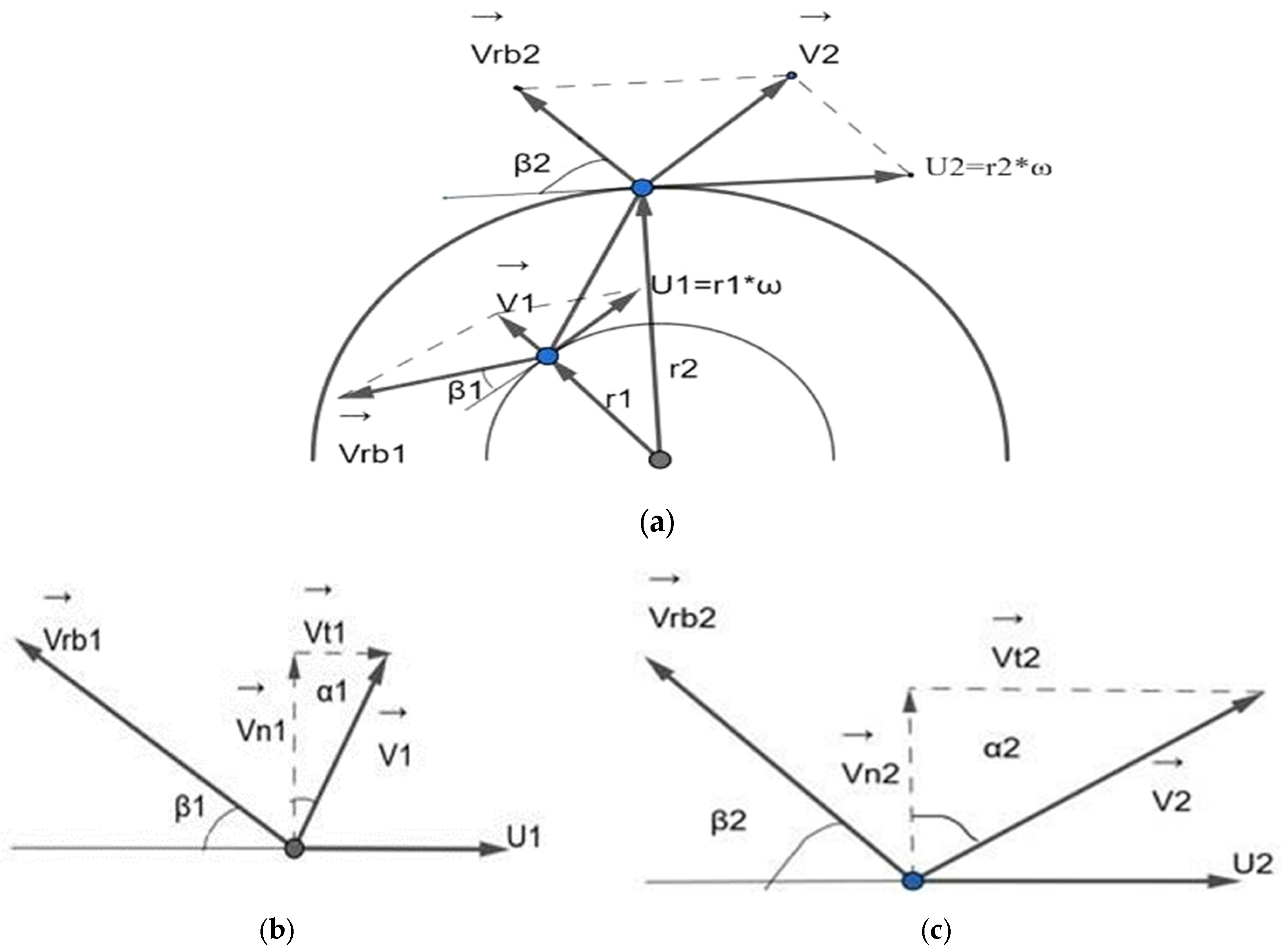
is the vector sum of the speed of the rotor wheel U and the flow speed relative to the blade Processes 13 01617 i002
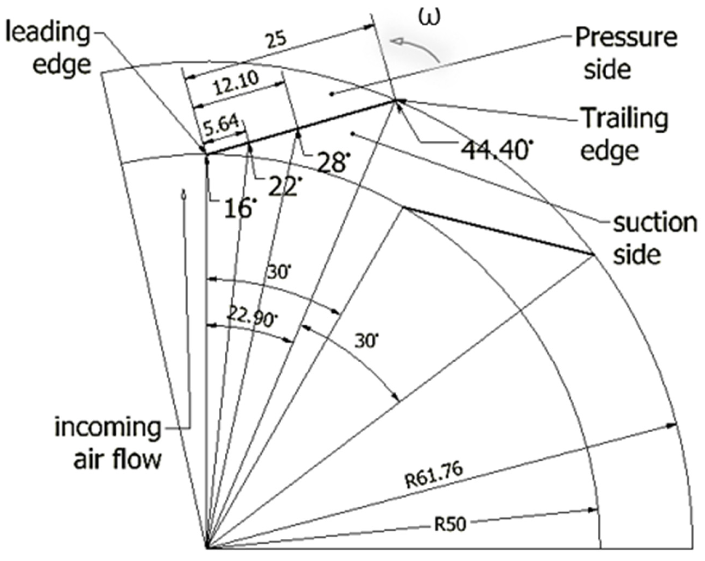
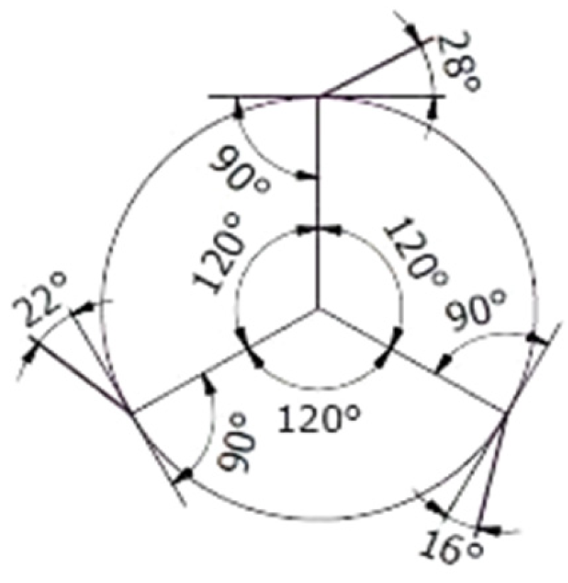
. It is evident that both the flow velocity relative to the blade Vrb1 and the normal component of the velocity Vn1 are greater than Vrb2 and Vn2, respectively. The tangential component Vt1 and the absolute velocity V1 are smaller than the tangential component Vt2 and the absolute velocity V2, respectively. The velocity polygons are drawn at the entry and exit ends of the fluid because they are the geometric points where the entry and exit angles are measured, which, in turn, define the inclination of the channel between blades through which the fluid circulates. In an idealized design situation, the flow relative to the rotor is assumed to enter and exit tangentially to the blade profile at each section, but the exact value of the angle between the flow of the fluid and the blade at each instant is random. Because of this situation the present experimentation uses angles with values of the interval defined by β1 and β2. These reasons are what induce the authors to take discrete values of angles of possible incidences, starting from the range of angles found between the closed extremes in β1 and the open extremes in β2, to evaluate the wear when the particles dragged by the fluid impact the blade at (0.08, 23, 48) % of blade length and (16°, 22°, 28°) of incidence angle, respectively, as seen in Figure 2.
The behavior of the vectors in the velocity polygons at the entrance and exit of the inter-blade channel (Figure 2) is explained because the flow within the channel between blades is subject to a change in cross-sectional area that forces it to increase its speed. Locally, as this trajectory is not constant, the acceleration vector changes direction, and, consequently, the direction and magnitude of each of the components of the velocity vector will vary, even when the movement of the flow behaves approximately parallel to the surface of the blade [7].
When induced, draft centrifugal fans move gases contaminated with solid particles; these particles impact the surface of the blade at the speed of the fluid that circulates through the inter blades channel, causing wear and loss of blade mass. This unequal distribution of mass in the rotor causes static and dynamic imbalance. Rotating machines, such as the centrifugal fan, require permanent care to optimize their good performance, safety, and useful life.
Erosive wear is common in today’s industry. The conduction of particles within a fluid is present both in the movement of air by means of fans or through pipes as well as in the movement of liquid materials with particle entrainment.
In the cases of particle conduction through a flow, the phenomenon is basically the same; it is a particle moved by the flow and therefore with kinetic energy. This energy with which the particle moves is responsible for damage to the worn element. For this reason, erosion is considered the loss of material from a solid surface due to relative movement in contact with a fluid containing solid particles [8,9,10].
Considering the conductive flow, the case of conduction in a gaseous medium (erosion in a gaseous medium) and conduction in a liquid medium (sludge) is usually differentiated [11].
Taking into account the basic wear mechanism, in both cases, there is a particle that will cause deformation and removal of material at a level greater than the atomic level and whose action can be limited to the shear displacement of the particle by its own means, which differentiates it from the case of the groove abrasion [12].
Erosive wear due to the action of fluids occurs in fans that work in atmospheres with high concentrations of particles. An analysis of the behavior of the flow and the particles that travel with it is complex since it will depend, among other aspects, on the flow rate and speed of the fluid.
The effect of the breakdown of the boundary layer and the contraction of the flow vein produces turbulence in the blade where the phenomenon occurs. If particles are transported in the fluid, an increase in their concentration occurs at that point.
It is important to note that, for the same aerodynamic design of a centrifugal fan, the variation in the flow rate to be transferred and the delivery load will cause a variation in the angle with which the fluid enters the channel between the blades (angle of attack). This change in the angle of attack will cause displacement along the blade profile of the point where the boundary layer rupture occurs and the contraction of the flow vein. This situation complicates the analysis significantly [13]. Different investigations have been carried out to try to establish the rules of the behavior of this phenomenon [14,15,16,17], and the present experiment is an attempt to obtain results that shed light on the rules of that behavior.
According to the work of Cardillo et al. [14], the greatest erosion occurs in the blade entry zone, as shown in Figure 3, coinciding with the separation zone of the boundary layer and the appearance of eddies. This behavior is in correspondence with previous experimental results [10].
In Figure 4, the velocity behavior in the fluid is shown, and the turbulence and recirculation of the flow at the leading edge of the blade can be clearly seen (area inside the circle) [17].
Typically, the angle of the blade in this area with respect to the tangent to the entrance circle is 16°, but the path of the fluid with respect to the surface of the blade is affected by the meridional and tangential components of the velocity [18], so, in reality, this angle varies depending on the operation of the fan.
From the point of view of erosive wear, the angle of incidence of the particle on the solid surface, in conjunction with the properties of the material, will define the greater or lesser wear of the equipment. Because of this, it is important to know the effect on wear that a change in the fan-operating regime will cause. The factors that will influence this behavior will be the speed of movement of the particle and the angle of attack [19,20], which is measured between the baseline of the blade and the relative speed of the fluid.
It has been determined that the movement of the gas flow at the inlet of the inter-blade channel for a family of fans with straight trailing blades [16] normally occurs with angles between the flow and the blade surface at the leading edge ranging between 20° and 38° degrees approximately. It is important to know the influence of the variation between the extreme values of this range on wear. Likewise, if the rotor tangential speed varies for the same family of fans, the flow speed will vary, and, consequently, the speed of the particle transferred by the flow will vary depending on the size of the fan. By determining these influences, it will be possible to relate the erosion on the fan blades to its dimensions and operating regime, which is very useful in its design, as will be seen later.
It should be noted that when considering multiphase flow, the solid particles in the flow may present variations in their number and trajectory, depending on their size, especially in the eddy areas and the rupture of the boundary layer, but the majority should follow the general behavior of the bearing flow [9,21,22,23].
The characteristics of the material are fundamental in the wear behavior in the face of variations in the speed and angle of incidence of the particles. If we start from the movement of the particle on the material, including the possibility of impact, we find that the material displaced by the particle will depend on the plastic capacity of the material and the way in which the deformation is distributed in perpendicular axes [21,22,23]
Although it is generally accepted that materials with great plasticity behave well against erosion at small angles [24,25], the exact behavior will depend on the material and the angle analyzed, which is why it is necessary to conduct tests under conditions close to those of operation.
The complex nature of wear conditions is the variety of wear tests, in such a way that the appropriate test will be the one that deals with the real wear situation, placing special emphasis on simulating the system to be studied [8].
A literature review, like N. Aldi’s, highlights experimental studies for measuring wear on large and heavy fans. To achieve this, expensive test rigs, such as jet impact benches are built and installed. This research combines experimental and numerical methods, considering the precedent that “the intensity of erosion depends on the dynamic characteristics of the particles, especially the velocity and impact angle”. The results show how different regions (rotating and stationary walls) are subject to different impact behaviors, making it difficult to design the position of the wear-resistant plate [26].
There are also many numerical studies to determine the wear behavior in large fans. One of them is by N. Aldi, who, for numerical studies, divides the erosive particles into small and large sizes and manages to show how the small particles are strongly influenced by turbulence and secondary flows; they have the tendency to be driven by the fluid and are more affected by the drag force. On the other hand, large particles, influenced by inertia, deviate. In the first stage of fluid movement, it causes impacts from the leading edge to the middle of the pressure side of the blades; with the continuous movement of the fluid in the channel between blades, the particles continue to repeatedly collide on the pressure side until the trailing edge [27].
In order to achieve the objective of evaluating the material wear of the rotor blades of a small centrifugal fan, a particular way of carrying out experimental tests is proposed using a sludge bucket installation, considering, as a system, the geometry of the blade and the behavior of the fluid of the channel between the blades for different rotor revolutions and different flow values, with a known angle of attack and pre-established angles of incidence.

2. Experimental Details
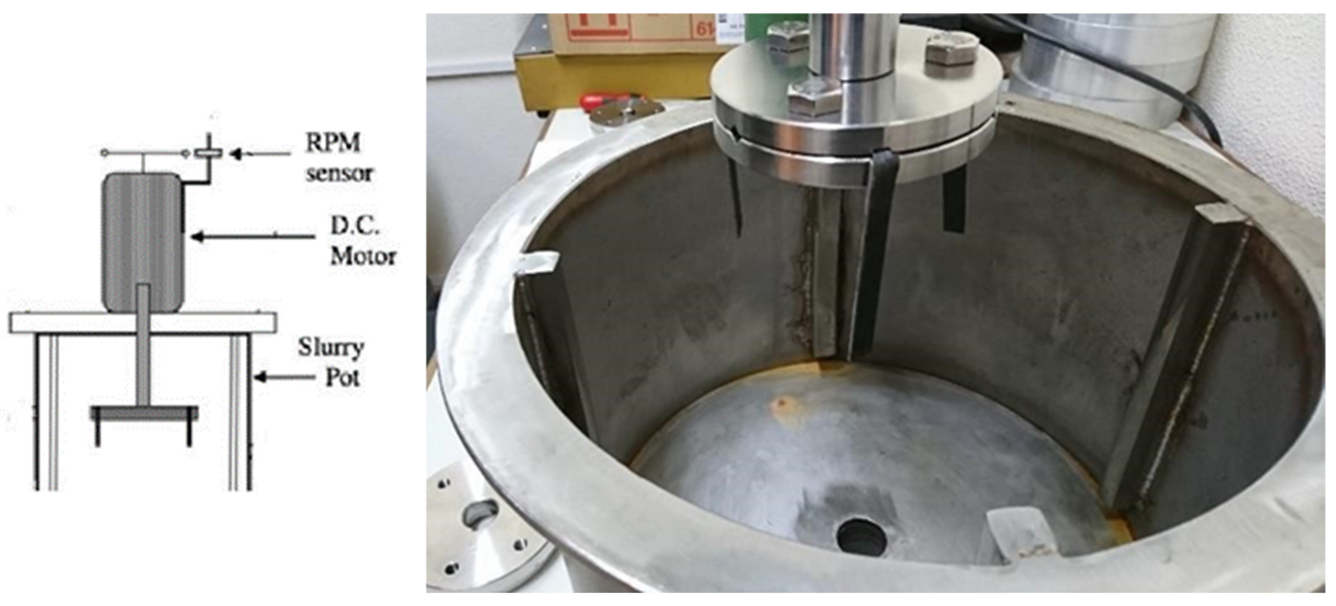
2.1. Methodology

In the analysis of the influencing factors on erosive wear in the fans of the family studied [18], the material used in them was ASTM A36 steel, with a maximum carbon content of 0.3% and with thicknesses of 1.8 mm. This allows us to more closely achieve the real conditions that prevail in the fan, influenced by the technological history of the material.
For the erosion test, the ideal installation would be a fan with the same characteristics as the family studied, but this leads to very long test times to obtain appreciable results.
Similarly, using air as a carrier fluid is more like the real situation of the fan, but the design of the test facilities generally offers a blowing system (jet) that does not guarantee approaching the real movement conditions in the fan, where particles travel in wider open spaces and vary their direction of motion due to the creation of turbulence.
The air can be considered incompressible as it passes through the low- and medium-pressure fan, so its behavior can be compared to the liquid pump, given that the pressure increase Dp is small. This increase for low-quality machines is Dp ≤ 100 mbar and for high quality machines Dp ≤ 30 mbar. Compressibility does not affect the design, so the fan is designed as a hydraulic turbomachine.
Analyzing these factors, it was determined to use a sludge erosion test installation, as shown in Figure 5. This installation allows the erosive medium to be dosed in water to obtain a desired aggressive medium and thereby shorten the test times without differing from the basic action of particles in low-pressure fans. The erosion installation also allows us to simulate the behavior of the fan using blade-shaped samples. With this arrangement, the samples would act in a similar way to the fan blades but without the confinement created by the inter-blade channel. Figure S2 shows the guide for the actions of this methodology used in the experimentation, and Figure 5 shows the layout and shape of the installation.
Silica sand was used as the aggressive element. The analysis of the sand was carried out using optical methods on a total of 230 analyzed fields. According to the observation, grains are predominantly subangular.
The granulometric analysis showed that the main fraction of the sand had diameters less than 1 mm and greater than 0.5 mm (70% of the sample) with a predominance of values greater than 0.6 mm and less than 0.71 mm, which reaches 27% of the total sample.
These dimensions are not totally comparable, at least apparently, with those normally present in fans that move in contaminated atmospheres. Generally, these are ashes, dusts, etc., which are characterized by having a very small dimension. However, it should be considered that the movement of small particles in a medium with a low load-bearing capacity, such as air, can be comparable to the movement of larger particles in a medium with a higher load-bearing capacity, such as a liquid. The advantage of using larger particles and a higher-density medium lies in increasing the kinetic energy of the impact and therefore the erosion phenomenon, which will allow for more precise discrimination of the influence of the factors that are intended to be assessed in less time of testing.

2.2. Test Parameters

The test was carried out, keeping the sand concentration constant at 100 g/L of water.
The test conditions are shown in Table 1. The controlled variables were the angle of incidence of the fluid on the samples, the tangential speed of displacement of the samples (v) and the space traveled (s).
The tangential speed was controlled through the rotation frequency of the shaft, keeping the dimensions of the sample holder constant. The rotation frequency is recorded using the equipment control system, with an accuracy of 0.1 rpm, which produces a tangential speed precision of 0.0314 m/s.
Three values of tangential speed were used: 2, 4, and 6 m/s. The values were selected, covering the common values of fluid movement into the fan, related to the blades.
The values of the incidence angle used were 16, 22, and 28 degrees and were measured using an adjustable goniometer with a precision of 0.1°. These values were selected via analysis of the relative angles of the fluid movement at the end of the inter-blade channel, where the wear is greater in fans.
The samples were made from 1.8 mm thick plates of ASTM A36 steel, without any treatment. They were cut in the form of 100 mm long and 10 mm wide sheets (exposed portion), with a thickening for fixation at one end. Figure 6 shows the configuration of the specimens and their fixation; also sketched is the position of the samples and their angular position in the rotor of the test machine. In each test, three samples were placed in the sample holder, one for each test angle, to guarantee the absence of other factors when evaluating the influence of the angle.
Erosion was evaluated by the relative weight loss of the samples. The relationship between the weight loss suffered after a journey of 573,012 m, and the initial weight of the samples was taken as an indicator of erosive wear (w). Intermediate measurements were carried at 143,253 and 286,506 m, and each trial was replicated randomly to obtain at least three reliable values.
For weight measurements, a Denver Instrument balance (TB 215 B) with a capacity of 60 g and sensitivity of 0.01 mg was used.
The damage suffered by the surfaces during the test, particularly the orientation of the groves, was examined via observation in a JEOL JEM 1010 scanning electron microscope. For this analysis, the samples tested with the three angles of incidence at the different speeds were used at the end of the test. This analysis enables us to know how close the test used produces a behavior like the movement of the particles in the fan, as reported [14,26,27].

Results

The results of the test are shown in Table 1. It shows the averages of the wear index for the weighing carried out after each run, as well as the variance of these averages. The wear index (mass loss relative to the mass of the sample) allows the results to be independent of mass variations between samples.

3. Results and Discussion

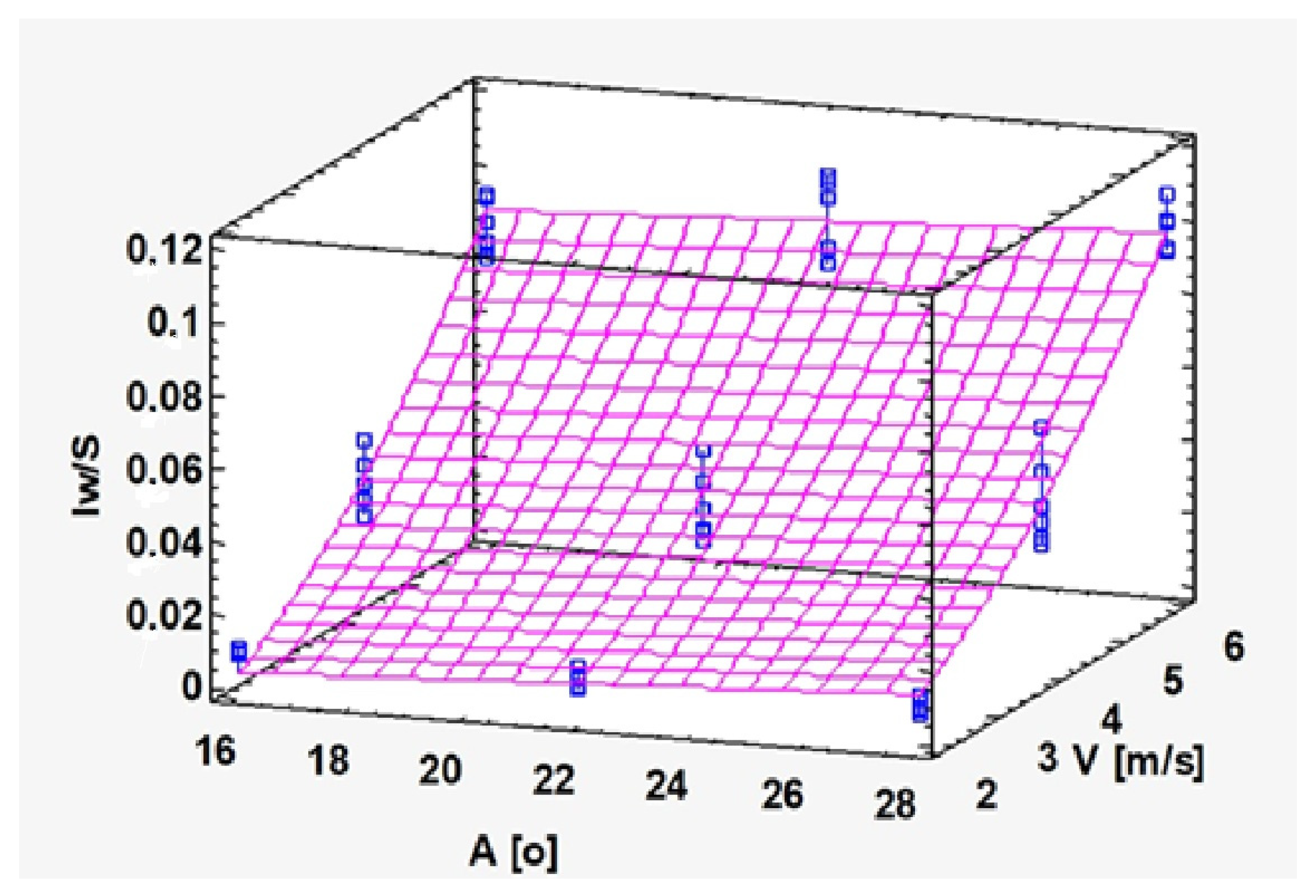
3.1. Correlation Between Variables

The results obtained in the tests are graphed in the following Figure 7 and Figure 8, which show the behavior of the different combinations of angle, speed, and distance evaluated.
In the graph of Figure 7, with an increasing test speed, the magnitude of wear increases for the same distance traveled. It is also notable that the differences in behavior that occurs when increasing the angle are very small for the speed of 2 m/s but increase progressively with the increase in speed, the differences being marked for the speed of 6 m/s. This behavior can be determined when selecting the fan design parameters.
This influence of speed is observed more clearly in Figure 8. The grouping of the wear curves along the test run as a function of the applied speed is clearly observed.
To obtain a function capable of interacting with the software Invencenty and give a value of erosion expected under the different values of the operating parameters of the fan, a correlation analysis was carried out. The stepwise multilinear regression method was used, working with a complete aleatory model with variables of the test: velocity (V) and angle (A). These variables relate to the relative velocity of the flown and blade and angles of attack and incidence of the fluid on the blade.
The wear rate (Iw) per distance traveled (Iw/s) was taken as the dependent variable. Speed and angle, their powers, and their interactions were included in the model as independent variables to explore the potential combination of factors. After eliminating non-significant variables, the final expression of the model is shown below:
w/s =−0.01884 + 0.00073 A + 0.00267 V 2
The model has an adjusted correlation coefficient R2 = 95.1%. The standard error of the estimate is 0.00807933 mg/g-m. The variance analysis is shown in Table 2.
Figure 9 below shows the response surface corresponding to the adjusted model obtained. It shows that the relative wear increases significantly with the increase in speed, in a quadratic manner, while the variation in the angle exerts a much smaller influence. This result is important since it shows that the element with the greatest influence on the design to minimize erosion will be the speed while the angle can be varied without causing a significant impact. This behavior allows us to approach the design of the fans without major restrictions in the selection of the blade shape, always within the range of angles analyzed, that is, from 16 to 28 degrees
On the other hand, it must be considered that the flow planned for the fan will depend not only on its dimensions but also on the speed. Considering that this variable affects wear in a quadratic manner, a combination of dimensions and speeds should be sought in the design, which allows for obtaining optimal delivery with a minimum of wear.

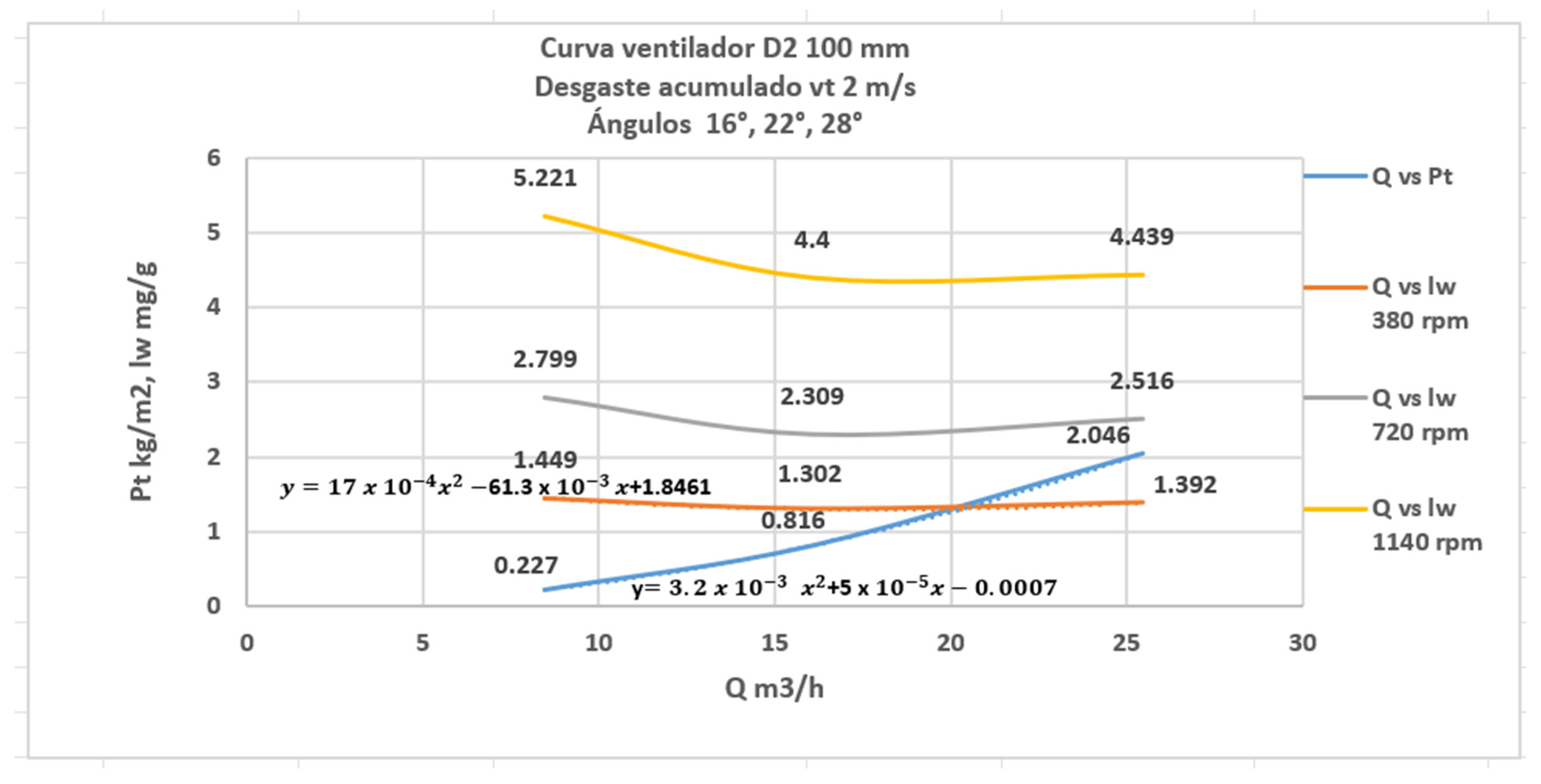
3.2. Characteristic Curve of the C4-70 Family Fan, 100 mm Rotor, and Accumulated Wear Curves

Figure 10 shows the characteristic curve of the fan, flow (Q) vs. total pressure (Pt), for the revolutions of 380, 720, 1140, and the accumulated wear curves (lw) considering the same for the revolution configuration of the shaft installation transmission
Relating the values obtained from the erosion behavior with the aerodynamic design parameters of the centrifugal fan of the C4-70 family, it is found that when the fan works with revolutions between 814 and 815 rpm, for a tangential speed of 2 m/s and flow rate of 20.16 m3/h, a cumulative wear of 1.3123608 mg/g is recorded, caused by the impact of solid particles dragged by the flow that could impact the surface of the blade when the angle is 22°24′.
For the same rotor diameter, an increase in revolutions results in an increase in flow. The tangential speed of each revolution and the constant radius establishes an increasing relationship between the rotor revolutions and the tangential speed, which is the quadratic variable of the equation for the cumulated wear obtained. Analyzing the speed polygon at the exit of the channel between blades, the tangential speed of the fan is greater than at the inlet; this is also the behavior of the speed relative to the flow, which is why the flow rate is also greater; then, it can be stated that the higher the flow rate, the greater the cumulated wear on the blade surface in the boundary layer rupture region. Experimentation has shown that there is a fan-operating regime in which you should not work if you want to avoid wear, even when it has been designed for a specific family with a certain angle of attack.
Having analyzed the geometric parameters, such as angle of entry of the fluid into the channel between the blades and the aerodynamic flow parameter that is dependent on the rotor rpm, for the design of the C4-70 family of centrifugal fans, it can be stated that their influence on the accumulated wear of the blade measured at three angles of incidence of the fluid along the blade has a linear behavior for the angle of incidence and quadratic behavior for the speed of the particle.

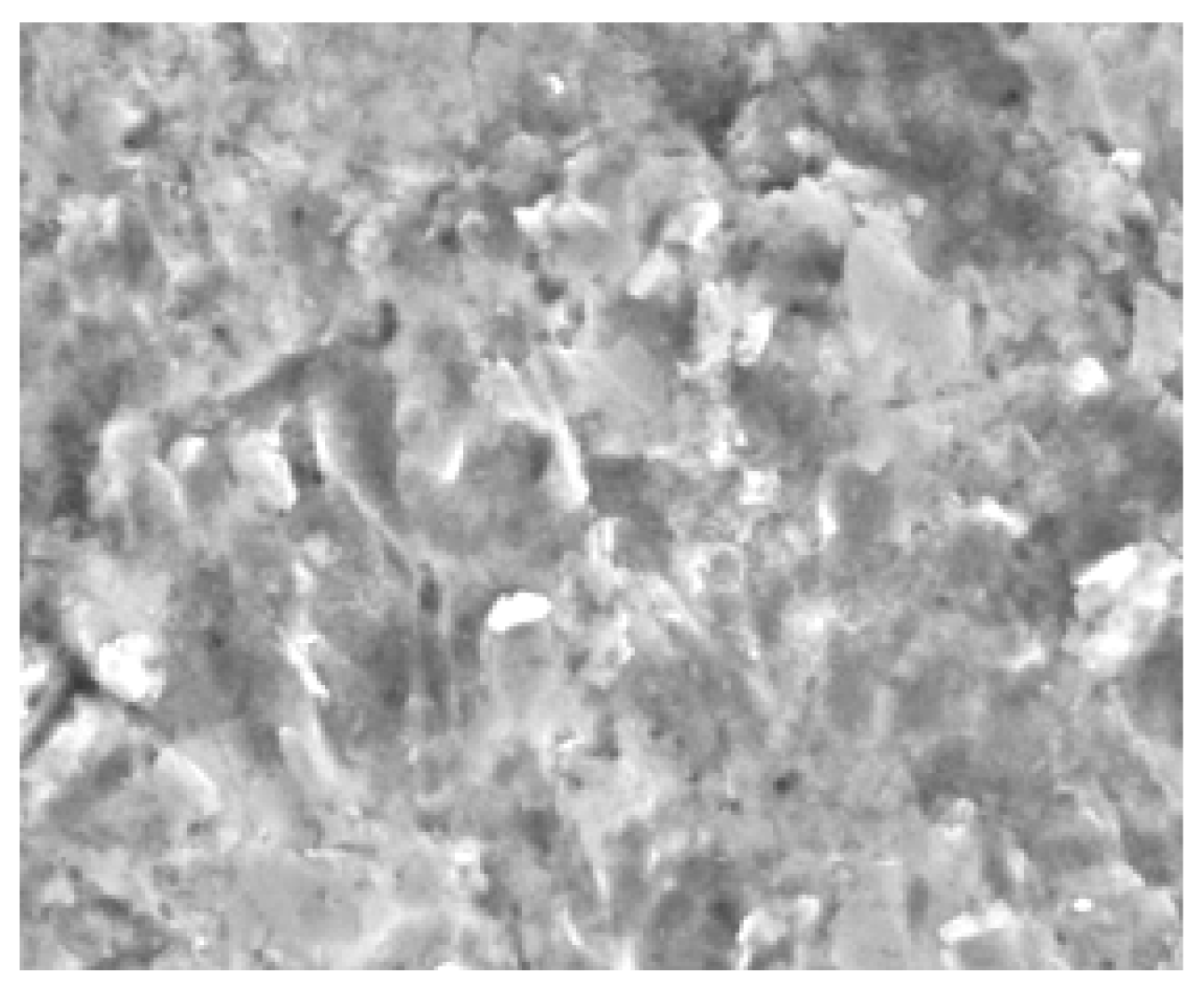
3.3. Metallographic Observation

From the analysis of the surface of the samples, it can be concluded that the behavior is similar in all cases, with some damage, but with the same general pattern in the grooves of the material by the erosive particles. The leading-edge area of the sample has a groove mainly oriented transversely to the edge. This is the behavior observed in Figure 11 and Figure 12. As you move towards the interior of the sample, groove directions without transverse orientation and randomly oriented ones appear, as well as impact marks that do not correspond to the small angles of incidence tested. This shows that the test used resembles the dispersion of the particles flow at the leading edge of the fan, and there are vortices or eddies in the leading-edge area. Furthermore, much of the groove is linear perpendicular to the edge, which validates the action of the leading edge.

4. Conclusions

  • Relative wear increases significantly with increasing speed, in a quadratic manner, while changing the angle has a linear influence.
  • There are differences in the behavior of the increase in wear that occur when the angle of incidence increases; they are very small for the speed of 2 m/s, but they increase progressively with the increase in speed, the differences mostly being marked for the speed of 6 m/s.
  • The working pressures of the fan are a function of the absolute speed V2 at the blade exit, of which the tangential speed in the inter-blade channel is a component.
  • When the 100 mm rotor fan of the C4-70 family works with revolutions between 814 and 815 rpm, for a tangential speed of 2 m/s and flow rate of 20.16 m3/h, a cumulative wear of 1.3124 mg/g is recorded, which is caused by the impact of solid particles carried by the flow that could impact the surface of the blade when the angle is 22°24′.
  • There is a limitation on the number of blade replica samples that can be tested simultaneously at the sludge erosion test facility.
  • Although the channel between blades implemented in the sludge tank is larger than the one that the fluid runs through in the centrifugal fan, the wear evaluation is carried out with great approximation to reality.
  • Based on the correlation found between the variables, future work could consider coatings, groove depth, and surface roughness.

Supplementary Materials

The following supporting information can be downloaded at: https://www.mdpi.com/article/10.3390/pr13051617/s1, Figure S1: Geometric parameters in mm of the C4-70 centrifugal fan, 12 backward blades; Figure S2: Actions for the implementation of the methodology.

Author Contributions

Methodology, L.G.; Investigation, L.G. and J.M.; Project administration, S.A. All authors have read and agreed to the published version of the manuscript.

Funding

This research received no external funding.

Data Availability Statement

The original contributions presented in this study are included in the article/Supplementary Material. Further inquiries can be directed to the corresponding author.

Conflicts of Interest

The authors declare no conflict of interest.

Nomenclature

β1fluid entry angle (degree)
β2exit angle (degree)
V1absolute velocity at the angle of entry of the fluid (m/s)
V2absolute velocity at the angle of exit of the fluid (m/s)
Vn1normal component at the angle of entry of the fluid (m/s)
Vn2normal component at the angle of exit of the fluid (m/s)
Vt1tangential component at the angle of entry of the fluid (m/s)
Vt2tangential component at the angle of exit of the fluid (m/s)
Vrb1flow speed relative to the blade at the angle of entry of the fluid (m/s)
Vrb2flow speed relative to the blade at the angle of exit of the fluid (m/s)
Vindependent variable velocity relative to the fluid (m/s)
Aindependent variable angles of attack and incidence of the fluid on the blade (degree)
Iwwear (mg/g)
Qcaudal (m3/s)
Pttotal pressure (kg/m2)

References

  1. Mataix, C. Mecánica de Fluídos y Máquinas Hidráulicas; Mexico D.F.: Oxford, UK, 1982. [Google Scholar]
  2. Ragauskas, P.; Tetsmann, I.; Jasevičius, R. The Optimization of the Geometry of the Centrifugal Fan at Different Design Points. Appl. Sci. 2024, 14, 3530. [Google Scholar] [CrossRef]
  3. Shao, W.; Feng, J.; Zhang, F.; Wang, S.; Li, Y.; Lv, J. Aerodynamic Performance Optimization of Centrifugal Fan Blade for Air System of Self-Propelled Cotton-Picking Machine. Agriculture 2023, 13, 1579. [Google Scholar] [CrossRef]
  4. Li, Z.; Ye, X.; Wei, Y. Investigation on Vortex Characteristics of a Multi-Blade Centrifugal Fan near Volute Outlet Region. Processes 2020, 8, 1240. [Google Scholar] [CrossRef]
  5. Fox, R.W.; McDonald, A.T. Introducción a la Mecánica de Fluidos; McGraw Hill Interamericana: Mexico City, Mexico, 1989. [Google Scholar]
  6. Lopez, G.B.; Arla, S.; Garcia, R. InvenCenty: Software para la enseñanza del diseño aerodinámico de una familia de ventiladores centrífugos de alta eficiencia. In InnoEducaTIC; Palmas, U.d.L., Ed.; Universidad de Las Palmas: Las Palmas de Gran Canaria, Spain, 2015. [Google Scholar]
  7. Schlichting, H. Boundary Layer Theory, 7th ed.; McGraw Hill: New York, NY, USA, 1979. [Google Scholar]
  8. Bayer, R.G. Mechanical Wear Fundamentals and Testing; Maecel Dekker Inc.: New York, NY, USA, 2004. [Google Scholar]
  9. Rawat, A.; Singh, S.N.; Seshadri, V. Erosion wear studies on high concentration fly ash slurries. Wear 2017, 378–379, 114–125. [Google Scholar] [CrossRef]
  10. Singh, G.; Singh, S.; Singh Grewal, J. Erosion wear characterisation of DLC and AlCrNbased coated AISI-304/316 steels. Surf. Eng. 2019, 35, 304–316. [Google Scholar] [CrossRef]
  11. ASM International Handbook Committee. Friction, Lubrication, and Wear Technology; ASM: Almere, The Netherlands, 1995; Volume 18. [Google Scholar]
  12. Shitole, P.P.; Gawande, S.H.; Desale, G.R.; Nandre, B.D. Effect of Impacting Particle Kinetic Energy on Slurry Erosion Wear. J. Bio Tribo Corros. 2015, 1, 29. [Google Scholar] [CrossRef]
  13. Solomahovoy, T. (Ed.) Centrifugal Fans; Machinoestraenie: Moscow, Russia, 1975. [Google Scholar]
  14. Cardillo, L.; Corsini, A.; Delibra, G.; Rispoli, F.; Sheard, A.G.; Venturini, P. Simulation of particle-laden flows in a large centrifugal fan for erosion prediction. In ASME Turbo Expo 2014; ASME: Düsseldorf, Germany, 2014. [Google Scholar]
  15. Parsi, M.; Kara, M.; Agrawal, M.; Kesana, N.; Jatale, A.; Sharma, P.; Shirazi, S. CFD simulation of sand particle erosion under multiphase flow conditions. Wear 2017, 376–377, 1176–1184. [Google Scholar] [CrossRef]
  16. Noon, A.A.; Kim, M.-H. Erosion wear on centrifugal pump casing due to slurry flow. Wear 2016, 264–365, 103–111. [Google Scholar] [CrossRef]
  17. Tanit, D.J.; Leonardo, B.; José, L.R. Proyecto de optimización de un ventilador centrífugo mediante dinámica de fluidos computacional (CFD) y comparación con mediciones experimentales. Espacios 2017, 38, 4. [Google Scholar]
  18. Lopez, G.B. Elaboración del algoritmo matemático para el diseño de una familia de ventiladores centrífugos. In Ciencias de la Energía y Mecánica; Universidad de Fuerzas Armadas: Sangolquí, Ecuador, 2016. [Google Scholar]
  19. Tabakoff, W.; Kotwal, R.; Hamed, A. Erosion study of different materials affected by coal ash particles. Wear 1979, 52, 161–173. [Google Scholar] [CrossRef]
  20. Corsini, A.; Marchegiani, A.; Rispoli, F.; Venturini, P.; Sheard, A.G. Predicting Blade Leading Edge Erosion in an Axial Induced Draft Fan. J. Eng. Gas. Turbines Power 2012, 134, 9. [Google Scholar] [CrossRef]
  21. Arabnejad, H.; Mansouri, A.; Shirazi, S.; McLaury, B. Abrasion erosion modeling in particulate flow. Wear 2017, 376–377, 1194–1199. [Google Scholar] [CrossRef]
  22. EL-Saied, A.F.; Gobran, M.H.; Hassan, H.Z. Erosion of an Axial Transonic Fan due to dust ingestion. Am. J. Aerosp. Eng. 2015, 2, 47–63. [Google Scholar] [CrossRef]
  23. Nandrea, B.D.; Desaleb, G.R. Study the Effect of Impact Angle on Slurry Erosion Wear of Four Different Ductile Materials. Mater. Today Proc. 2018, 5, 7561–7570. [Google Scholar] [CrossRef]
  24. Abd-Elrhman, Y.M.; Abouel-Kasem, A.; Emara, K.; Ahmed, S.M. Effect of Impact Angle on Slurry Erosion Behaviour and Mechanisms of Carburized AISI 5117 Steel. J. Eng. Sci. Assiut Univ. 2014, 41, 137–157. [Google Scholar] [CrossRef]
  25. Laguna-Camacho, J.R.; Vite-Torres, M.; Gallardo-Hernández, E.A.; Vera-Cárdenas, E.E. Solid Particle Erosion on Different Metallic Materials. In Tribology in Engineering; Intech Open: London, UK, 2013. [Google Scholar]
  26. Aldi, N.; Casari, N.; Pinelli, M.; Suman, A.; Vulpio, A.; Saccenti, P.; Beretta, R.; Fortini, A.; Merlin, M. Erosion behavior on a large-sized centrifugal fan. In Proceedings of the 13th European Conference on Turbomachinery Thermodynamics and Fluid Dynamics ETC13, Euroturbo, Lausanne, Switzerland, 9–12 April 2019. [Google Scholar]
  27. Aldi, N.; Casari, N.; Pinelli, M.; Suman, A.; Vulpio, A.; Mantovani, O.; Saccenti, P. Evaluation of the Wear-Resistant Plate Performance on Different Locations over the Flow Path of a Large-Sized Heavy-Duty Centrifugal Fan. Int. J. Turbomach. Propuls. Power 2022, 7, 32. [Google Scholar] [CrossRef]
Figure 1. Behavior of the fluid velocity vectors at the entry and exit of the blade, when the fluid passes through the channel between blades [5]. (a): Absolute speed as the sum of the speed relative to the blade and the speed of the rotor; (b): speed polygon at the entrance of the blade; (c) speed polygon at the blade exit.
Processes 13 01617 g001
Figure 2. Sample of an inter-blade channel of the C4-70 family centrifugal fan and the chosen incidence angles: 16°, 22°, 28°, which have the location shown on the length of the blade. For the geometric parameters of the fan, see Figure S1.
Processes 13 01617 g002
Figure 3. Simulation of high erosion areas. The darker areas correspond to the greatest erosion [14].
Processes 13 01617 g003
Figure 4. Simulation of flows in the fan. Plotting of velocity vectors (minimum: blue, maximum: red) [14].
Processes 13 01617 g004
Figure 5. Scheme and layout of the experimental installation.
Processes 13 01617 g005
Figure 6. Sketch of the configuration of the anchoring of the specimens in the sample holder of the tank of the trough erosion installation.
Processes 13 01617 g006
Figure 7. Results obtained for the different combinations of angle and speed. The bars correspond to the distances traveled in each trial (in meters).
Processes 13 01617 g007
Figure 8. Wear curves along the test run.
Processes 13 01617 g008
Figure 9. Behavior of the wear index relative to the space traveled (Iw/s) for the different combinations of angle (A) and tangential speed (V).
Processes 13 01617 g009
Figure 10. Characteristic curve of the fan Q vs. Pt and Q vs. lw, for rpm 380, 720, 1140, and vt 2 m/s.
Processes 13 01617 g010
Figure 11. Leading edge of the sample.
Processes 13 01617 g011
Figure 12. Area towards the interior of the sample.
Processes 13 01617 g012
Table 1. Results obtained in the trial.
Angle
[°]
Speed
[m/s]
Wear Index Iw [mg/g] Average Deviation [mg/g]
Distance Traveled [m]
143,253286,506573,012143,253286,506573,012
16214,49627,99252,2130.01890.19830.5051
22213,02323,09044,0020.44840.15610.6093
28213,92125,16044,3950.29900.45970.5934
16451,73593,506185,6161.43422.00351.1129
22456,141102,489186,0071.78301.94081.3761
28469,937124,762236,5802.28642.63581.1766
166132,925234,300448,2270.06740.94411.2333
226140,515269,603516,0480.10700.96231.1234
286154,576289,574534,2250.00210.08840.2251
Table 2. Variance analysis and confidence intervals for coefficient estimates.
Variance Analysis
FountainSum of SquaresGlMiddle SquareF-Ratiop-Value
Model0.067720.0338518.540.0000
Residue0.003329510.000065
Total (Corr.)0.07102553
95.0% Confidence Intervals for Coefficient Estimates
Mistake
ParameterEstimateStandardLower LimitUpper Limit
CONSTANT−0.018840.00529−0.02946−0.00822
To [or]0.000730.000220.000280.00118
V20.002670.000080.002500.00284
R-squared = 95.3128 percent. R-squared (adjusted for df) = 95.129 percent. Std: standard error = 0.00807933. Mean absolute error = 0.00668556. Durbin–Watson statistic = 1.12065 (p = 0.0003).
Disclaimer/Publisher’s Note: The statements, opinions and data contained in all publications are solely those of the individual author(s) and contributor(s) and not of MDPI and/or the editor(s). MDPI and/or the editor(s) disclaim responsibility for any injury to people or property resulting from any ideas, methods, instructions or products referred to in the content.

