Article

Particle Motion and Gas–Solid Heat Exchange Enhancement in Rotary Drums with Aligned/Separated Flight

by
Yewei He
1,
Dianyu E
2,3 and
Zeyi Jiang
1,4,*
1
School of Energy and Environmental Engineering, University of Science and Technology Beijing, Beijing 100083, China
2
Jiangxi Provincial Key Laboratory of Particle Technology, Jiangxi University of Science and Technology, Nanchang 330013, China
3
Research Centre for Intelligent Mineral Processing & Metallurgy, International Institute for Innovation, Jiangxi University of Science and Technology, Nanchang 330013, China
4
Beijing Key Laboratory for Energy Saving and Emission Reduction of Metallurgical Industry, University of Science and Technology Beijing, Beijing 100083, China
*
Author to whom correspondence should be addressed.
Processes 2025, 13(5), 1594; https://doi.org/10.3390/pr13051594
Submission received: 16 April 2025 / Revised: 18 May 2025 / Accepted: 19 May 2025 / Published: 20 May 2025
(This article belongs to the Section Particle Processes)

Abstract

:
In a waste heat recovery rotary drum with flights (RDF), particle lifting enhances gas–solid contact but also increases the complexity of particle motion in both radial and axial directions. In this study, a long rotary drum model applicable to both aligned and separated flights was developed. The discrete element method was employed to investigate the effects of the inclination angle, feed rate, and rotation speed on particle dynamics and heat exchange performance. Additionally, a gas–solid heat exchange model was formulated to quantitatively assess the system’s heat recovery efficiency, power recovery, and power consumption. The results indicated that particle motion exhibited greater randomness along the axial direction, and the proposed long-drum model effectively captured the key parameters influencing particle dynamics. The heat exchange capacity of the RDF was closely related to the filling degree, which was found to be most sensitive to the inclination angle. Although the separated flight formed a spiral-shaped particle curtain and significantly enhanced the uniformity of the particle distribution, its heat exchange capacity was lower than that of the aligned flight, and it increased the construction cost by more than 30%. Under all operating conditions, the total system power consumption remained below 20% of the recovered power output.

1. Introduction

The waste heat recovery rotary drum has been extensively adopted in various industrial processes due to its structural simplicity and high throughput capacity [1,2]. This device is primarily used to recover the sensible heat from high-temperature bulk materials exhibiting adequate flowability [3,4]. Currently, such systems typically employ water as the cooling medium, with a series of heat exchange tubes uniformly installed along the drum’s inner wall, through which cooling water circulates to achieve indirect heat exchange with the material [5]. However, the cooling water temperature resulting from indirect heat exchange remains around 70–80 °C, which constitutes low-grade heat that is challenging to utilize effectively, thereby limiting overall energy efficiency [6]. To enhance heat recovery efficiency, researchers have proposed installing internal flights to disperse particles and form a particle curtain while replacing water with gas to enable direct gas–solid contact heat exchange [7,8]. The purified high-temperature gas can subsequently be used for raw material preheating or power generation, thereby facilitating the cascade utilization of waste heat. The flight shape and operating parameters in rotary drums with flights (RDFs) exert a significant influence on particle motion, and the resulting spatial distribution is closely coupled with gas–solid heat exchange performance. Therefore, to improve the heat exchange performance and processing capacity of the RDF system, it is essential to systematically investigate the underlying mechanisms through which flight shape and operating parameters affect particle dynamics and spatial distribution.
The structural forms of flights are commonly categorized into single-segment and multi-segment configurations based on their geometric characteristics [9,10]. Due to structural limitations, single-segment flights (typically straight and continuous in form) are generally inefficient in conveying particles to the central region of the RDF and are therefore mainly employed in particle-mixing systems [11,12]. In contrast, multi-segment flights—such as the widely used two- (usually L-shaped, composed of two connected short plates joined at an angle of approximately 90°) or three-segment (comprising three spaced short plates with adjustable segment lengths) structures—offer enhanced material-holding capacity and a greater terminal discharge angle, thereby allowing more particles to engage in effective heat and mass exchange with the gas phase [13,14]. Seidenbecher et al. [15] and Xie et al. [16] examined the internal heat transfer processes in rotary drums using experimental and numerical methods, respectively, and concluded that the incorporation of flights significantly improves thermal performance. Silveira et al. [17] employed the discrete element method (DEM) to investigate the effects of two- and three-segment flights on particle distribution within the drum. The results demonstrated that an optimized flight structure can concurrently achieve high particle curtain density and improved spatial uniformity, with lifted particles covering up to 40% of the RDF’s central region. Karali et al. [18,19,20,21] and Ajayi et al. [22] performed systematic studies using experimental rotary drum setups combined with image analysis techniques to explore the influence of flights on particle lifting behavior, highlighting that filling degree and particle drop height are key determinants of heat transfer efficiency. Researchers have therefore proposed various structural refinements and modifications to flight designs in an effort to further enhance the heat exchange efficiency of RDFs. Priessen et al. [23] found that a segmented flight shape can induce a “pseudo-reflux” phenomenon, in which certain particles exhibit localized reverse movement. To mitigate this effect, they proposed adding baffle plates on both sides of the flight to augment its material-holding capacity. Silveira et al. [24] further evaluated the impact of separated flight arrangements on heat transfer performance and reported that, when the separation angle was set to 15°, the particle concentration in the central region of the RDF increased by 24.6%, while particle distribution non-uniformity decreased by 38.5% compared to the unseparated configuration.
In rotary drums, particle movement along the axial direction is typically described by residence time or the diffusion coefficient [25,26]. However, as a fluid–solid two-phase flow system, particle motion is inherently complex [27], and the presence of flights further increases this complexity. Bongo et al. [28] compared the effects of single- and two-segment flights on particle behavior and concluded that two-segment flights notably prolonged residence time and increased the fraction of lifted particles. Zhang et al. [29,30] utilized particle tracking velocimetry to examine the influence of two-segment flights on particle residence behavior and curtain characteristics, demonstrating that, within a certain parameter range, increasing the number of flights improved both residence time and curtain density. Zhu et al. [31] simulated particle motion in a drum equipped with inclined flights using DEM and further adopted response surface methodology to evaluate the interactive effects of the flight inclination angle, feed rate, and rotation speed. Jian et al. [32] applied the CFD-DEM approach to analyze gas–solid flow and heat transfer in the drum and observed that increasing the feed rate and rotation speed reduced the particle outlet temperature. Although prior studies have explored the influence of flight shapes and operating parameters on particle motion, a comprehensive understanding of particle behavior in both radial and axial directions within rotary drums remains insufficient. In particular, from the perspective of heat exchange enhancement, in-depth analyses of particle dynamics in RDF systems remain limited. Therefore, systematically elucidating the influence of flight structure and operating parameters on particle transport behavior and heat transfer efficiency within RDFs is of great significance for advancing their practical application in industrial waste heat recovery.
This study centered on the RDF system and employed DEM simulations to analyze particle motion characteristics under varying flight shapes and operating conditions, thereby assessing the gas–solid heat exchange performance of the system. In addition, a gas–solid heat exchange model was formulated to compute the temperature distribution of both phases inside the drum, and key performance metrics, including exergy efficiency, power recovery, and power consumption, were comprehensively analyzed. The long-drum model effectively revealed the key operating parameters governing particle transport behavior. Compared with aligned flights, separated flights significantly improved particle distribution uniformity but exhibited lower heat transfer performance, which led to increased construction cost. The findings of this study offer theoretical insights and methodological guidance for the structural design, parameter optimization, and operational strategy development of high-efficiency RDF systems, thereby providing practical value for engineering applications.

2. Numerical Procedure
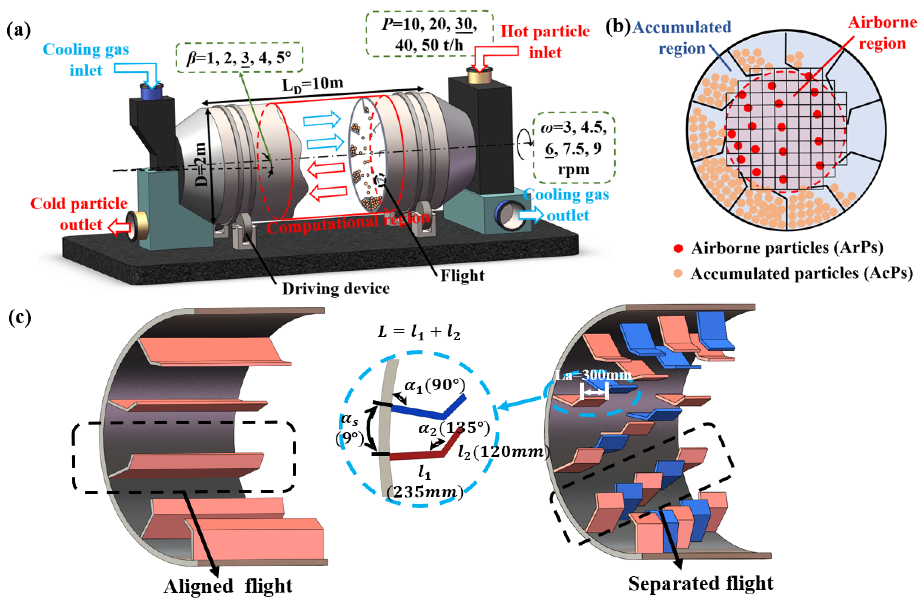
2.1. Physical Model

As shown in Figure 1a, the RDF is a heat exchange device that recovers sensible heat via direct contact in a counter-current gas–solid arrangement. The main body of the device comprises a long cylindrical drum inclined at a fixed angle and rotating around its axis. Under the combined effect of drum rotation and internal flights, solid particles are progressively conveyed from the elevated inlet to the lower outlet along the axial direction, forming a continuous particle stream. In practical engineering applications, the RDF length can vary from several meters to several tens of meters, depending on the designed throughput capacity. Previous simulation studies have revealed that unstable particle motion regions of approximately 0.8 m exist near both the inlet and outlet of the RDF, where stable particle curtains are challenging to form. To balance computational efficiency and simulation accuracy, a simplified RDF model with a length of 3 m was developed in this study, focusing on particle motion along the axial direction. The computational domain is outlined by red lines in Figure 1a. The RDF model has an inner diameter of 2000 mm, with 10 flights uniformly distributed at each radial cross-section to promote continuous particle dispersion. Particles lifted and projected by the flights are referred to as airborne particles (ArPs), residing in the RDF’s airborne region. Particles settled at the drum bottom and within the flights are defined as accumulated particles (AcPs), primarily located in the bulk accumulation region, as illustrated in Figure 1b.

2.2. Discrete Element Method

In the DEM, the motion state of each particle is individually tracked. When particle i contacts another particle j (or wall j), both its translational and rotational motions are governed by Newton’s second law. These motions can be described using the following equations of motion [33].
m i d v i d t = m i g + j = 1 F i j n + F i j t
Ι i d ω i d t = j = 1 T t , i j + T r , i j
where m i is the mass of particle i, v i is the translational velocity of particle i, g is the gravitational acceleration, F i j n is the normal contact force exerted by particle j on particle i, F i j t is the tangential contact force exerted by particle j on particle i, Ι i is the moment of inertia of the particle i, ω i is the angular velocity of particle i, T t , i j is generated by tangential force and induces the rotation of particle i, and T r , i j , commonly known as the rolling friction torque, is induced by asymmetric normal forces and resists the relative rotation between particles.
In this study, the Hertz–Mindlin contact model was adopted to simulate the interparticle contact forces. Compared with other commonly used contact models, the Hertz–Mindlin model more accurately captures the mechanical behavior of particle collisions [34,35]. The fundamental equations of this model are presented in Table S1 of the Supplementary Materials. The particle motion was solved using the commercial discrete element software EDEM v2.7, developed by Altair.

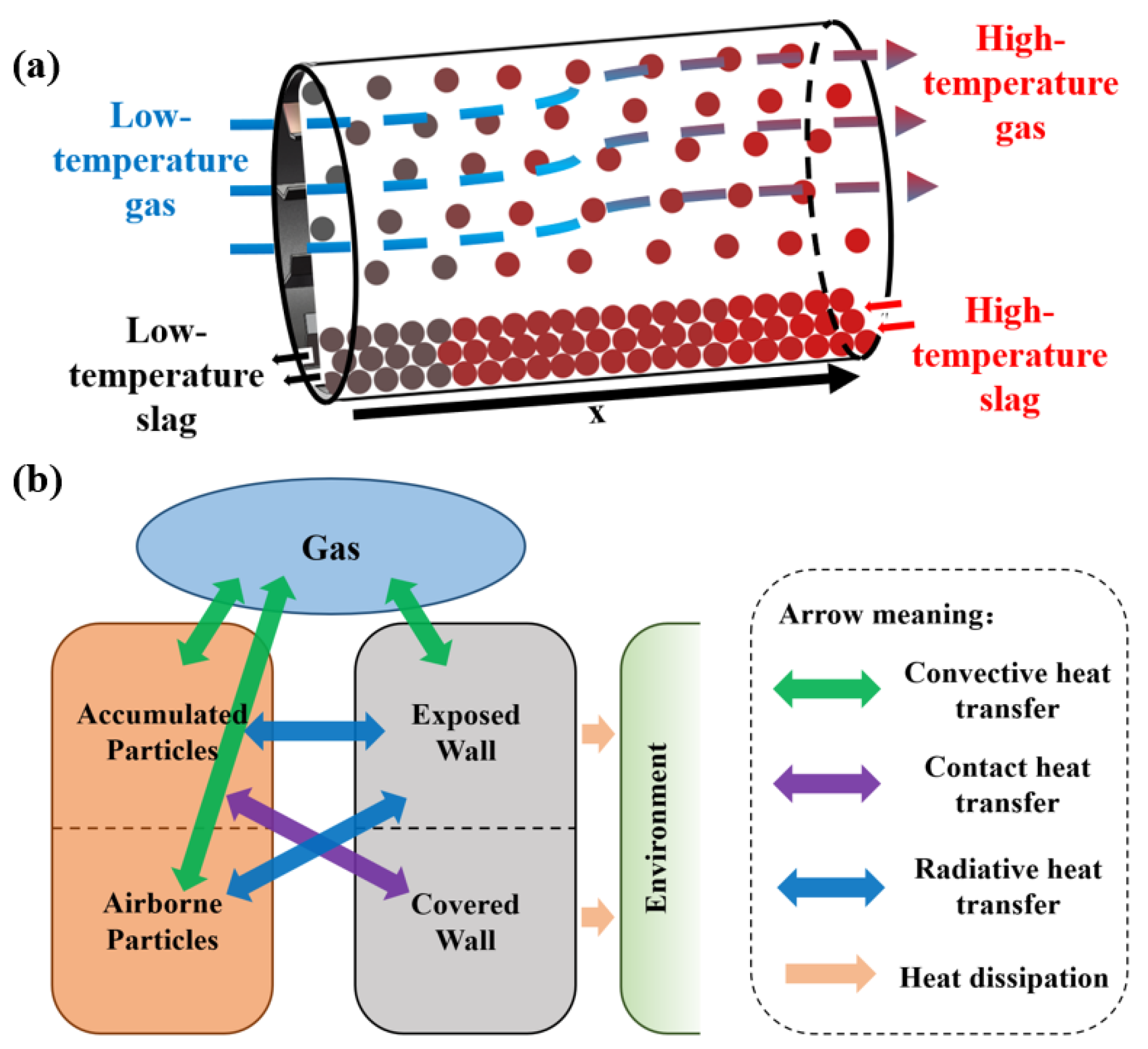
2.3. Gas–Solid Heat Exchange Model

In this study, the particle spatial distribution derived from DEM simulations was used as the initial condition to construct a one-dimensional, steady-state gas–solid heat exchange model along the drum axis, with the aim of predicting the temperature distribution of the gas and solid phases within the RDF. The model was formulated based on the following simplifying assumptions: (1) Heat loss at the inlet and outlet was neglected, assuming that the heat released by particles was either absorbed by the cooling gas or transferred through the drum wall to the surroundings, as such losses typically account for only a small portion of the total energy exchange. (2) The gas was assumed to flow uniformly outside the AcPs region, with a uniform temperature distribution across each radial cross-section. (3) With the model focusing on axial temperature distribution, particles were assumed to be fully mixed in the radial direction, resulting in a uniform particle temperature across each cross-section. (4) ArPs were assumed to be uniformly distributed within the airborne region, with no local accumulation or depletion. (5) Internal temperature gradients within particles were neglected, with each particle assumed to maintain a uniform internal temperature, and internal thermal conduction ignored, given the small particle size of granulated blast furnace slag and its relatively high thermal conductivity. Based on the above assumptions, the heat exchange processes in the RDF were classified into the following seven modes, as depicted in Figure 2: (a) radiation between the ArPs and the exposed wall surface; (b) convection between the ArPs and the gas; (c) conduction between the AcPs and the covered wall surface; (d) radiation between the AcPs and the exposed wall surface; (e) convection between the AcPs and the gas; (f) convection between the exposed wall and the gas; and (g) heat dissipation from the drum wall to the external environment.
The heat exchange model within the drum consists of the continuity equations for both the gas and granular bed, the energy balance equations for the gas and granular bed, the heat dissipation equation for the drum wall to the environment, and the ideal gas state equation:
The continuity equation of the gas:
ρ g u g x = 0
where ρ g is the gas density, u g is the gas velocity, and x is the drum length.
The continuity equation of the granular bed:
ρ s u s x = 0
where ρ s is the granular bed density; u s is the granular bed velocity.
The energy equation of the gas:
x 1 ε ρ g u g C p g T g = x 1 ε λ g T g x + ( h A c P s g L A c P s A + h A r P s g N A r P s A p A ) T s T g + h e w g L e w A ( T w T g )
where ε is the filling degree, C p g is the specific heat capacity of the gas, T g is the gas-phase temperature, λ g is the thermal conductivity of the gas, h A c P s g is the convective heat transfer coefficient between the AcPs and gas, L A c P s is the arc contact length between the AcPs and gas, A is the drum cross-sectional area, h A r P s g is the convective heat transfer coefficient between the ArPs and gas, N A r P s is the number of ArPs per unit length, A p is the particle surface area, T s is the granular bed temperature, h e w g is the convective heat transfer coefficient between the exposed wall and the gas, L e w is the arc contact length between the exposed wall and the gas, and T w is the wall temperature. The expressions for the heat transfer coefficients are provided in the Supplementary Materials.
The energy equation of the granular bed:
x ε ρ s u s C p s T s = x ε ( 1 σ ) λ s T s x + ( h A c P s g L A c P s A + h A r P s g N A r P s A p A ) T g T s + ( h A c P s c w L c w A + h r , A c P s e w L A c P s A + h r , A r P s e w N A r P s A p A ) T w T s
where C p s is the specific heat capacity of the granular bed, σ is the porosity of the AcPs, λ s is the thermal conductivity of the granular bed, h A c P s c w is the heat transfer coefficient between the granular bed and the covered wall, L c w is the arc contact length between the granular bed and the covered wall, h r , A c P s e w is the radiative heat transfer coefficient between the AcPs and the exposed wall, and h r , A r P s e w is the radiative heat transfer coefficient between the ArPs and the exposed wall.
The wall heat dissipation equation:
T w T a i = 1 3 ln ( r i + 1 / r i ) 2 π λ i + 1 2 π r 4 h w e = ( h A c P s c w L c w + h A c P s e w L A c P s + h A r P s e w N A r P s A p ) T s T w + h e w g L e w ( T g T w )
where T a is the ambient temperature, r 1 is the inner radius of the RDF, r 2 is r 1 plus the thickness of the wear-resistant layer, r 3 is r 2 plus the thickness of the thermal-protective coating, r 4 is r 3 plus the thickness of the insulating layer, and h w e is the heat transfer coefficient between the drum outer wall and the ambient environment.
The gas state equation:
p = ρ g R m T g M g
where R m is the ideal gas constant; M g is the molar mass of the gas.
A first-order upwind finite-difference scheme was employed to discretize the governing equations in the gas–solid heat exchange model, and the temperature distributions of both phases were solved using MATLAB R2023. The applicability and predictive capability of the proposed gas–solid heat exchange model in industrial rotary drums were evaluated by performing numerical simulations to determine the temperature distribution of the gas and solid phases within a real-scale industrial rotary kiln. The simulated temperature profiles showed good agreement with the corresponding experimental data in terms of overall trends, confirming that the model is capable of reliably predicting gas–solid heat exchange processes in industrial rotary systems. A detailed comparison between the simulated and experimental results is provided in Figure S1.

2.4. Data Processing

Based on the DEM simulation outputs, two parameters were defined in this study to quantitatively assess the heat exchange performance within the RDF: the enhanced heat exchange ratio (EHER) and the non-uniformity of particle distribution (NPD). After the particle motion reached a steady state, a statistical analysis was conducted on the two parameters. To ensure the representativeness of the statistical results, a 1.2 m axial segment at the center of the RDF was selected as the statistical region, thereby avoiding the unstable particle motion zones near both ends. It is worth noting that due to the continuous rotation of the drum, particle motion remains in a constantly evolving dynamic state, and the particle distribution at a single moment fails to represent the overall system behavior. Therefore, the dynamic evolution of particle distribution was incorporated during the parameter statistics process to enhance the representativeness of the EHER and NPD and improve the reliability of the computed results.
EHER is defined as the ratio of the total gas–solid heat exchange area in the presence of flights (including the surface area of particles in both the accumulated and airborne regions) to the total particle surface area in the absence of flights.
E H E R = A ¯ f , g r a n u l a r   b e d + A ¯ P , a c t i v e A g r a n u l a r   b e d
where A ¯ f , g r a n u l a r   b e d represents the total surface area of the particle bed in the accumulated region, A ¯ P , a c t i v e represents the statistically averaged active surface area of the particles in the airborne region, and A g r a n u l a r   b e d represents the particle bed surface area in the drum without flights, under the same filling degree condition.
During the statistical analysis, data collection was initiated when a given flight reached the 0° discharge angle (horizontal position), and particle motion data were sampled every 6° of drum rotation, resulting in 30 data sets, the average of which was used for the analysis. Given that the angular spacing between adjacent flights was set to 36°, one full flight cycle was divided into six equal intervals to capture the dynamic evolution of the particle curtain during the drum rotation. To reduce statistical deviations induced by random particle motion, the data were collected over five complete flight cycles (i.e., a continuous 180° rotation). A higher EHER value indicates a larger gas–solid direct contact area, reflecting greater heat exchange potential and thereby enhancing waste heat recovery efficiency.
NPD is employed to quantitatively evaluate the spatial distribution characteristics of particles in the central region of the RDF. The calculation procedure involves excluding the area occupied by flights and dividing the remaining statistical region into multiple equal-area grids. The proportion of particles in each grid relative to the total particle count is calculated, and the standard deviation of these proportions is used as a quantitative measure of distribution uniformity. As shown in Figure 1b, the selected statistical region is circular, and the grid division is based on the minimum bounding square that encloses the circular area. If AcPs are present within the statistical region, they are excluded from the NPD computation. Previous studies have shown that a grid resolution of 10 × 10 provides a good balance between statistical accuracy and computational efficiency. The corner grids of the bounding square lie entirely outside the airborne region and are thus excluded from the analysis, resulting in 88 effective grids used for statistical evaluation. A comparison of NPD values under different grid resolutions is presented in Figure S2.
N P D = 1 N c M i M M i M ¯ 2 N c
where N c represents the total number of grid cells, M i represents the number of particles in the i-th grid, and M represents the total number of particles in the airborne region.
The statistical method for NPD is consistent with that used for the EHER, with data collection based on the dynamic evolution of particle behavior during drum rotation. A higher NPD value indicates greater non-uniformity in particle distribution within the curtain, which diminishes gas–solid heat exchange efficiency and ultimately impairs waste heat recovery performance.

2.5. Simulation Conditions

Molten slag particles generated through centrifugal granulation were selected as the research object. Due to their high sphericity, spherical particles were adopted in the simulation model. If the actual particle size was directly used for modeling, the number of particles within the drum would reach several million, leading to an excessive computational load that fails to meet practical requirements for simulation efficiency. To enhance computational efficiency, the particle diameter was magnified by a factor of 15 in the simulation. This magnification factor was determined based on preliminary simulations of particle motion under varying particle diameters, which showed negligible deviation in particle behavior up to this scale. The detailed comparison is presented in Figure S3. Based on this adjustment, the contact parameters for molten slag particles proposed by Feng et al. [36] were adopted, and a dynamic repose angle calibration method was employed to recalibrate the contact parameters of the enlarged particles, thereby ensuring the consistency and accuracy of the simulation results. The physical and contact parameters used for the simulated particles are summarized in Table 1.
Two different flight shapes were selected, the aligned type and the separated type, with schematic diagrams provided in Figure 1c. Based on previous research findings, the key structural parameters of the flights were determined. The ratio of the flight length to the drum diameter (L/D), the bending position (l1/L), the installation angle (α1), the bending angle (α2), the segmentation length (La), and the separation angle (αs) were set to 0.177, 0.663, 90°, 135°, 300 mm, and 9°, respectively. The selection of the inclination angle, feed rate, and rotation speed was based on a combination of rotary dryer design manuals, relevant previous studies, and practical production requirements in steel plants [37,38]. A baseline condition was defined with an inclination angle of 3°, a feed rate of 30 t/h, and a rotation speed of 6 r/min, under which single-factor analyses of operating parameters were performed. The specific settings of the operating parameters are summarized in Table 2.

3. Result and Discussion

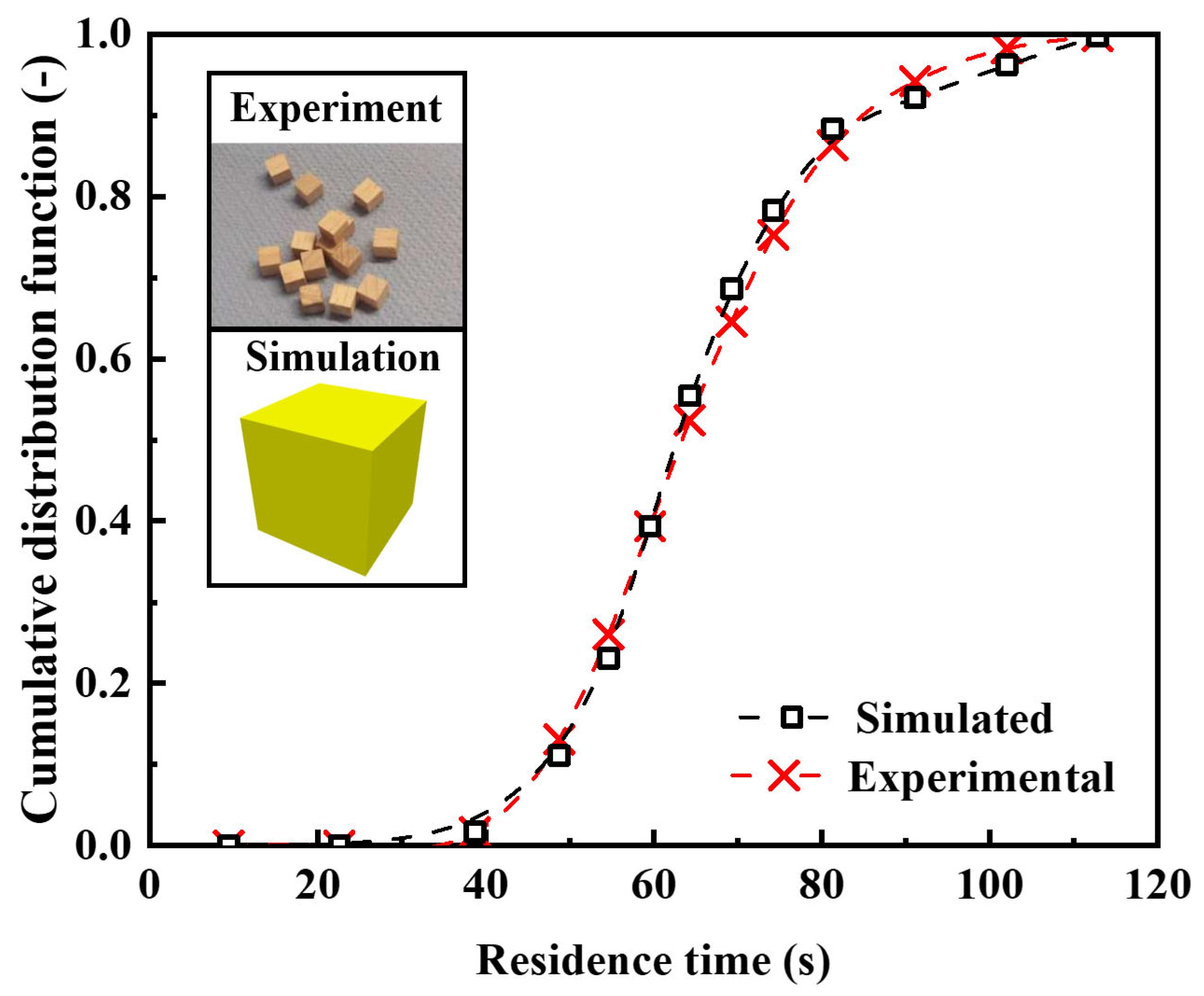
3.1. Model Validation

The reliability of the DEM simulation method was evaluated by referencing the rotary drum experiments conducted by Mahdavy et al. [39] and by developing a drum-particle model that replicated experimental conditions. The experimental setup comprised a drum with a length of 50 cm, an inner diameter of 8.4 cm, and an outer diameter of 9 cm. A variety of particles were employed in the experimental study, including cubic wooden particles, cuboid wooden particles, and cuboid ceramic particles. The experiments systematically investigated the effects of the rotation speed, drum inclination angle, and feed rate on particle behavior, with a particular focus on measuring particle residence time inside the drum. To validate the simulation approach, one specific experimental case was replicated, involving 6 mm wooden cubic particles subjected to a rotation speed of 7 rpm, an inclination of 3°, and a feed rate of 1.08 cm3/s. Numerical simulations and trajectory-tracking analyses were performed under these conditions to obtain the cumulative particle fraction as a function of outlet time (i.e., residence time). Figure 3 shows a comparison between the simulation results and experimental data, revealing strong agreement. This confirms that the constructed simulation model accurately replicated the experimental process and demonstrated a high level of reliability. It is therefore well suited for an in-depth analysis of particle axial motion characteristics in rotary drums.

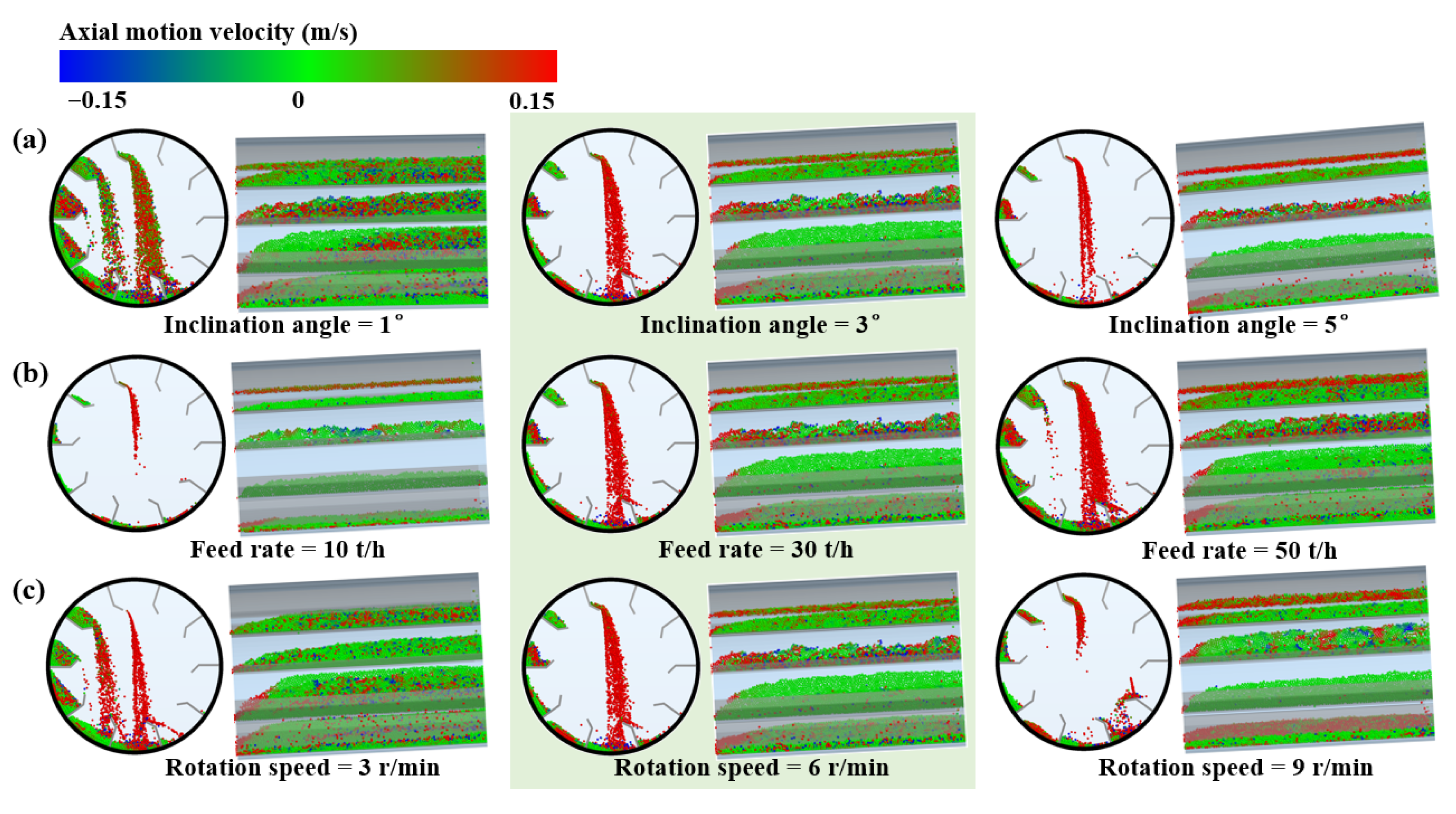
3.2. Effect of Operating Variables on Particle Motion

Figure 4 illustrates the effects of various operating parameters on particle distribution characteristics within the RDF equipped with aligned flights. As the inclination angle and rotation speed decreased, and the feed rate increased, the total particle quantity inside the drum increased significantly. The total amount of particles directly determines the filling degree of the drum. Under low filling degree conditions (e.g., inclination angle of 1°, feed rate of 10 t/h, and rotation speed of 9 r/min), the initial material-holding capacity of the flight at the horizontal position was insufficient to meet the design load or was only marginally overloaded, which resulted in a low particle curtain density and poor uniformity, thereby significantly reducing gas–solid heat exchange efficiency and waste heat recovery performance.
The axial movement of the particles was primarily concentrated in the ArPs, whereas the AcPs were restricted by interparticle collisions, with noticeable axial motion observed only at the surface layer of the accumulated particle bed. As the inclination angle increased, the overall axial migration rate of the ArPs accelerated, as indicated by the increased proportions of red and green particles. Changes in the feed rate and rotation speed exerted limited influence on the axial motion of the ArPs; however, increasing the rotation speed led to a larger final discharge angle of the flight, indicating that particles were discharged only at later angular positions. This implies a prolonged particle residence time within the flight.
Figure 5 shows the effects of various operating parameters on the particle distribution behavior under the separated flight. Compared with the aligned flight, the influence of the operating parameters on the total particle quantity within the RDF remained generally consistent. However, the particle motion characteristics in the radial and axial directions of the drum exhibited notable distinctions. Owing to the separated shape of the flights, a spiral-shaped particle curtain was formed in the airborne region, which significantly improved the uniformity of the particle distribution and thereby enhanced the consistency of the gas temperature distribution in both the radial and circumferential directions of the drum.
Unlike the aligned flights that discharged all the particles into the airborne region, the separated flights directed part of the particles into the airborne region, while the remaining fraction was discharged from both ends of the flight. This discharge pattern induced distinct axial fast-forward channels (red zones) and localized backflow pathways (blue zones) within the flight region. Moreover, with increasing total particle content in the drum, the axial migration and backflow became more pronounced, exhibiting enhanced flow stratification behavior.
Figure 6 presents the distributions of the particle axial velocity, filling degree, and reflux ratio under various operating parameters. The reflux ratio is defined as the proportion of particles moving against the drum inclination direction, relative to the total particle count. As shown in Figure 6a, the axial velocity increased nearly linearly with an increasing drum inclination angle. When the inclination angle was increased by a factor of five, the axial velocity also increased nearly fivefold, indicating a strong positive correlation. Variations in the feed rate exerted a relatively minor effect on the axial velocity, exhibiting a slight downward trend. With an increasing rotation speed, the growth of the axial velocity gradually plateaued, indicating a diminishing marginal effect.
In the rotary drum systems, the particle axial progression primarily depended on the displacement induced by the free-falling motion of the ArPs and the surface-layer flow of the particles at the top of the accumulated bed. Both motion mechanisms were directly governed by the drum inclination angle. As the inclination angle increased, the horizontal displacement between the ArPs’ landing position and the axial projection of their release point became larger, and the axial component of gravity was accordingly enhanced. Therefore, among all the operating parameters, the inclination angle had the most pronounced effect on the particle axial velocity.
Although an increase in rotation speed raised the number of particles lifted per unit time, it also enhanced the inertial force acting on the particles, leading to a larger final discharge angle of the flights and a more concentrated landing region on the right side of the drum’s radial cross-section (Figure 4c and Figure 5c). This prolonged the particle residence time within the flights and thereby suppressed the overall axial movement trend. The feed rate primarily determined the total number of particles entering the drum per unit time. As the particle quantity increased, the interparticle interactions intensified, increasing the hindering effects. As a result, the overall flowability of the particle bed was slightly reduced.
When the flight shape was switched from aligned to separated, the axial velocities of both the ArPs and AcPs increased. As the inclination angle increased, the difference in the average axial velocity between the two flight shapes continued to widen. When the inclination angle rose from 1° to 5°, the velocity difference increased nearly fivefold. In contrast, variations in the feed rate and rotation speed had only minor effects on the average velocity difference. The transition in the flight shape led to an overall increase in the average axial velocity of over 40%.
As shown in Figure 6b, the variation trend of the filling degree demonstrated a clear inverse relationship with the axial velocity. Compared to the aligned flight, the separated flight led to a lower overall filling degree in the drum due to its improved particle flowability. In practical applications, the optimal filling degree ranged between 15% and 20%. In this study, the filling degree approached the optimal range only when the inclination angle was 1°. A coordinated adjustment of the inclination angle, feed rate, and rotation speed was necessary to ensure that the system filling degree met the engineering requirements and that the flight achieved its design material-holding capacity at the initial discharge position. For the separated flight, structural baffles were optionally added to both sides to suppress the excessive axial motion of the particles and enhance the flight’s material-holding capacity. Notably, an increase in the feed rate raised the thermal load per unit time, thus necessitating a higher cooling airflow rate to ensure the material was cooled to the desired temperature. However, if the cooling airflow velocity was excessive, it interfered with the natural falling motion of the ArPs, leading to partial retention within the drum.
The reflux ratio decreased with an increasing inclination angle and rotation speed and also declined with a decreasing feed rate. The overall difference in the reflux ratio between the two flight shapes remained relatively small. Specifically, in the aligned flight, backflow mainly occurred at the surface of the accumulated particle bed, whereas in the separated flight, it was primarily concentrated within the flight regions. The sensitivity of the reflux ratio to the three operating parameters ranked in descending order as follows: inclination angle, rotation speed, and feed rate.
Figure 7 illustrates the distribution characteristics of the particle residence time under different operating conditions. When the aligned flight was adopted (Figure 7a), the probability density distribution of the particle residence time followed a normal distribution under all the operating conditions. Under this flight shape, the particle motion remained relatively stable, and the overall flow exhibited regularity in its distribution. As the inclination angle increased, the peak of the residence time distribution shifted leftward, and the distribution span decreased significantly. When the inclination angle rose from 1° to 5°, the average residence time decreased by approximately 4.3 times (from 128 to 30 s), and the span was reduced nearly fivefold (from 100 to 21 s). An increase in the feed rate resulted in a moderate rise in the average residence time; however, the increase was limited and had minimal impact on the distribution span. The effect of the rotation speed on the residence time distribution followed a similar trend to that of the inclination angle, except that the peak became more concentrated, while the reduction in span was less pronounced. When the rotation speed increased from 3 r/min to 9 r/min, the residence time span decreased by less than a factor of two (from 75 to 38 s).
After the separated flight was adopted (Figure 7b), the randomness of the particle motion increased significantly, and the characteristics of the residence time distribution changed markedly. Although the trends in the peak residence time under various operating parameters remained similar to those observed in the aligned flight, the overall residence time span was consistently broader. This indicated that some particles remained in a reflux state for extended periods, leading to a prolonged residence time and potential non-uniformity in the solid outlet temperature distribution. The increase in the residence time span was particularly pronounced under conditions of a low inclination angle and low rotation speed. When the inclination angle and rotation speed were set to 1° and 3 r/min, respectively, the change in the flight shape resulted in a 2.7-fold and 3.6-fold increase in the residence time span, respectively.

3.3. Capacity and Effectiveness of Heat Exchange

The effects of the flight shapes and operating parameters on the heat exchange capacity and efficiency of the RDF were systematically analyzed. The customized evaluation parameters, EHER and NPD, offered a more intuitive evaluation of heat exchange enhancement and homogenization, as shown in Figure 8. The EHER increased significantly with a decreasing inclination angle and an increasing feed rate while exhibiting a nonlinear trend of “decrease followed by increase” in response to changes in the rotation speed. The NPD increased with an increasing inclination angle and rotation speed, and with a decreasing feed rate, indicating a trend toward a more non-uniform particle distribution. The change in the flight shape did not significantly affect the response trends of the EHER and NPD to variations in the operating parameters.
A reduction in the inclination angle and an increase in the feed rate had particularly pronounced effects on enhancing the gas–solid heat exchange area. Notably, the EHER exhibited exponential growth as the inclination angle decreased. The influence of the rotation speed on the EHER was more complex. Under low-speed conditions, the filling degree inside the drum remained relatively high, which enabled the flights to retain sufficient material and facilitated particle delivery to the airborne region. At higher rotation speeds, the frequency of particle lifting increased, which also contributed to gas–solid heat exchange to a certain extent.
When the flight shape was switched from aligned to separated, the EHER decreased by approximately 20%. However, the structural change significantly reduced the NPD, and the resulting spiral-shaped particle curtain exhibited improved distribution uniformity, which facilitated a more uniform gas–solid heat exchange. The lower filling degree was identified as the primary reason for the reduction in the EHER in the separated flight. Appropriately suppressing the excessive axial motion and particle reflux within the flight effectively mitigated this issue. Establishing an organized particle flow to form a dense and uniformly distributed spiral particle curtain was recognized as a key strategy for improving the heat exchange efficiency of the RDF system.
Based on the gas–solid heat exchange model and the gas–solid contact area derived from the DEM simulations, the temperature distributions of the gas and solid phases inside the drum were predicted, and the system’s exergy efficiency was subsequently evaluated. The exergy efficiency served as a quantitative indicator of the overall waste heat recovery performance of the RDF system. It was defined as the ratio of the gas outlet exergy to the solid inlet exergy, with the detailed calculation method provided in Formula (11) [40]. In all the simulation cases, the gas volumetric flow rate and drum length were set to 20,000 m3/h and 10 m, respectively.
η = E g , o u t E s , i n × 100 %
Figure 9 illustrated the effects of various operating parameters on the gas–solid temperature distribution and exergy efficiency. The gas–solid temperature distribution and exergy efficiency were closely correlated with the EHER, and all three exhibited consistent variation trends across different operating conditions.
Under the aligned flight (Figure 9a), reducing the inclination angle significantly enhanced gas–solid heat exchange performance. For example, when the inclination angle was set to 1°, the solid was cooled to 647 K, while the gas outlet temperature reached as high as 864 K. As the inclination angle decreased from 5° to 1°, the exergy efficiency increased significantly from 10.8% to 47.6%, highlighting the critical role of the filling degree in rotary drum gas–solid heat exchange systems. Changes in the feed rate had a limited impact on the solid outlet temperature but significantly elevated the gas outlet temperature. This occurred mainly because the increase in the feed rate not only improved the gas–solid contact but, more importantly, introduced a greater amount of sensible heat into the system. As a result, the solid cooling range varied only slightly, while the gas’s heat absorption capacity increased, leading to a substantial temperature rise. Accordingly, the exergy efficiency increased from 9.7% to 27.2%. The EHER values remained similar at both high and low rotation speeds; increasing the rotation speed did not effectively enhance gas–solid heat exchange but instead raised the overall energy consumption of the system.
Under the separated flight (Figure 9b), the gas–solid heat exchange performance and exergy efficiency were inferior to those observed under the aligned flight, primarily due to the lower filling degree. Overall, under both flight shapes, the exergy efficiency in most cases remained below 40%, and a significant gas–solid temperature difference persisted on the high-temperature side of the drum, indicating considerable potential for further waste heat recovery. The waste heat recovery performance of the drum could be further enhanced by extending the drum length or suppressing the excessive axial migration of particles to increase the filling degree.

3.4. Power Recovery and Consumption

To more comprehensively evaluate the waste heat recovery performance of the RDF system, the effective heat recovery power ( P e h r ) was calculated and analyzed. P e h r was defined as the difference between the net heat recovery power ( P h r ) and the total system power consumption. The total system power consumption comprised the drum rotation drive power ( P c r ), the additional power consumption of the centrifugal fan ( P c f ), and the auxiliary energy required for particle lifting ( P c l ), with the detailed calculation method provided in the Supplementary Material.
P e h r = P h r P c r P c f P c l
Figure 10 shows the recovered and consumed power of the system under various operating conditions. Under the aligned flight, except for the case with a feed rate of 10 t/h, the combined proportion of the drive power and additional power consumption relative to the total recovered waste heat power remained below 9%. Both the drive power and additional power consumption increased with a decreasing inclination angle and an increasing feed rate. Specifically, when the inclination angle decreased from 5° to 1° and the feed rate increased from 10 t/h to 50 t/h, the drive power increased by 74.1% and 72.3%, respectively, while the additional power consumption increased by 92.8% and 89.6%, respectively. The rotation speed had limited impact on the additional power consumption; however, when the speed increased from 3 r/min to 9 r/min, the drive power nearly doubled.
The effective heat recovery power increased linearly with a decreasing inclination angle and an increasing feed rate. The difference between the maximum and minimum values reached 2.65-fold and 5.63-fold, respectively, indicating that increasing the feed rate significantly enhanced the heat recovery capacity. However, the particle outlet temperature remained relatively high, which warranted further attention. At lower rotation speeds, higher recovery energy was achieved, while both the drive power and additional power consumption remained minimal. Under the corresponding condition, the effective heat recovery power reached 1321 kW.
Compared with the aligned flight, the separated flight exhibited slightly lower values in effective heat recovery power, drive power, and additional power consumption, although the overall variation trends remained consistent. When the inclination angle was below 2°, the feed rate was less than 20 t/h, and the rotation speed exceeded 7.5 r/min, the combined share of the drive power and additional power consumption exceeded 10% of the recovered heat power, reaching as high as 19.1% when the feed rate was 10 t/h. The effective heat recovery power increased markedly when the inclination angle was below 3° or the feed rate exceeded 30 t/h.
A further evaluation of the system’s performance and economic feasibility was conducted by calculating the required drum length to cool the solid to 700 K under different operating conditions. Based on this length, the corresponding heat recovery power and power consumption were estimated, as shown in Figure 11. The required drum length also served as a key reference for estimating equipment costs. As the inclination angle decreased, the required drum length was significantly reduced, potentially lowering the cost to as little as one-fourth of the original. When the feed rate was 50 t/h, the required drum lengths under the aligned and separated flight conditions were 88.5 m and 110.3 m, respectively. At this point, the gas–solid temperature difference on the high-temperature side was less than 20 K, indicating that the heat exchange process approached its thermodynamic limit, with both solid and gas outlet temperatures tending toward stabilization and limited potential for further thermal exchange. The rotation speed had a relatively minor influence on the required drum length, and the overall variation remained limited.
When the flight shape was switched from aligned to separated, the required drum length generally increased by over 30%, which significantly elevated the system’s construction cost. Under the condition of achieving the same cooling effect, the influence trends of the inclination angle and rotation speed on the ratio of total power consumption to recovered heat remained consistent with those observed under the fixed-length drum condition. As the feed rate increased, the proportion of total power consumption to recovered heat first increased and then decreased. For example, when the feed rate rose from 30 t/h to 50 t/h, the power consumption ratio increased by approximately 10%, while the heat recovery power rose by 43%. However, the corresponding increase in required drum length resulted in an estimated 2.5-fold increase in construction cost.
The payback period of the RDF system was governed by the trade-off among equipment construction cost, operational energy consumption, and economic return. Reasonable operational strategies played a critical role in enhancing heat recovery capability while controlling the overall system cost. Based on the operating parameters analyzed in this study, it was recommended that, for rotary drum-based waste heat recovery systems, the inclination angle remain below 2°, the rotation speed be maintained at 3 r/min, and the feed rate be kept within 30–40 t/h to achieve an optimal balance between heat recovery performance and system economic efficiency. Although the separated flight formed a spiral-shaped particle curtain that significantly improved particle distribution uniformity, the associated increase in particle mobility partially reduced gas–solid contact efficiency. Therefore, further structural optimization of the flight was required to appropriately suppress excessive axial particle motion and synergistically improve both heat exchange enhancement and distribution uniformity within the RDF system.

4. Conclusions

For RDF systems with different flight shapes and operating parameters, this study performed DEM-based numerical simulations of particle motion, systematically analyzed gas–solid heat exchange enhancement and homogenization characteristics, and predicted the internal temperature distribution using a gas–solid heat exchange model. On the basis of power consumption evaluation, the overall performance of the waste heat recovery process was comprehensively assessed. The main conclusions of this study are summarized as follows:
(1)
Particle motion in the axial direction of the drum exhibited greater randomness than in the radial direction. The use of a long-drum model enabled the identification of the true rheological characteristics of particle flow. Among all operating parameters, the inclination angle had the most pronounced effect on axial motion; as the inclination angle increased, the advancement speed of the particle bed increased approximately linearly, exhibiting a multiplicative growth trend. Compared with the aligned flight, the separated flight improved the overall flowability of the particle bed through a distinct discharge mechanism.
(2)
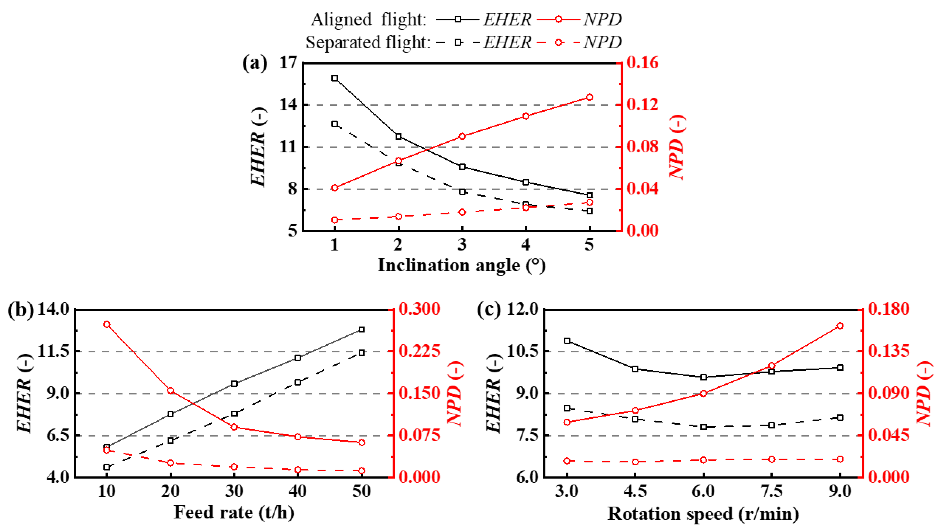
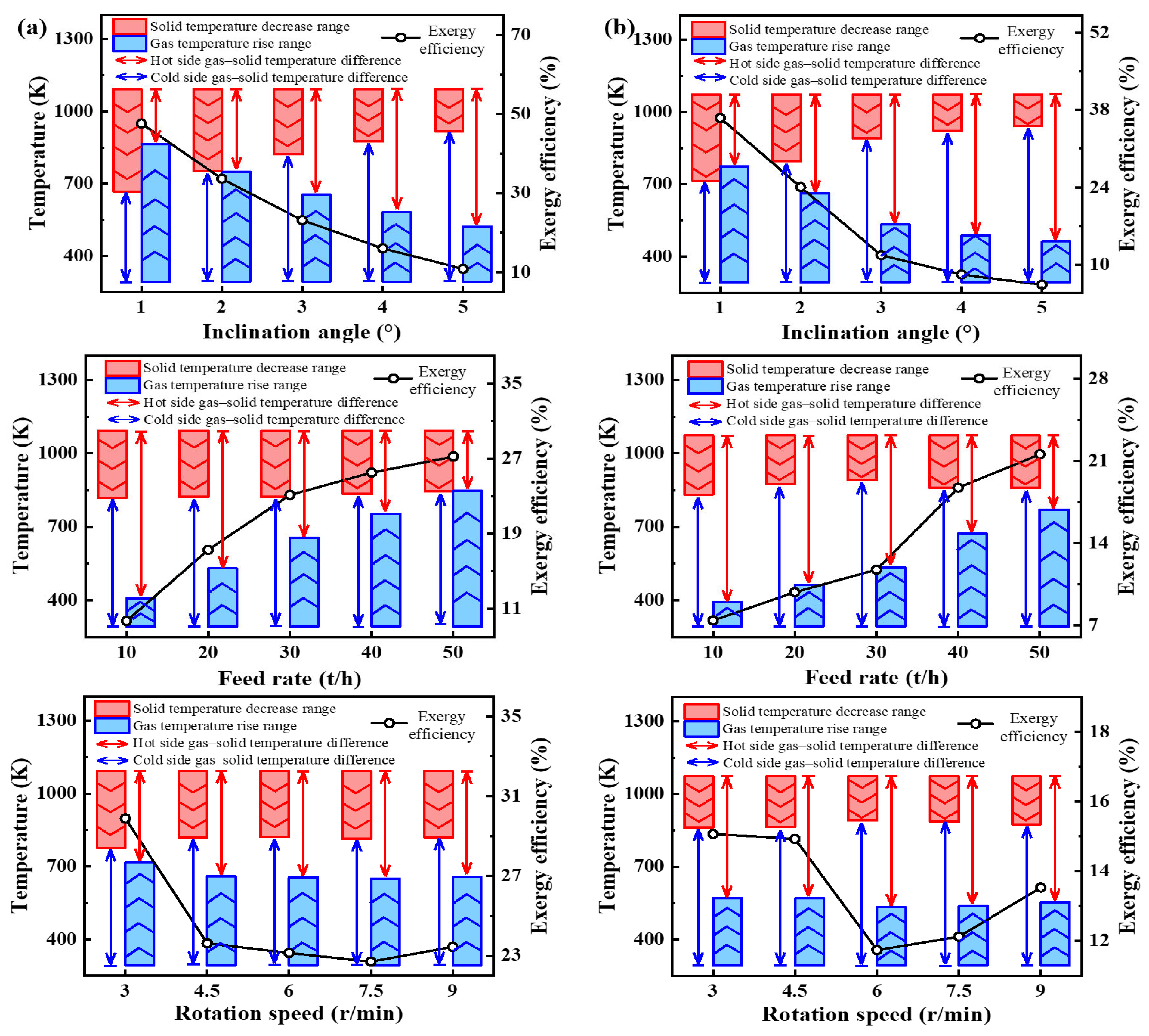
Reducing the inclination angle and increasing the feed rate significantly improved gas–solid contact, with the maximum enhancement of the heat exchange area exceeding a 2-fold increase, while also promoting a more uniform particle distribution. The rotation speed had a relatively minor influence on both heat exchange enhancement and distribution uniformity. The spiral particle curtain formed by the separated flight significantly improved distribution uniformity, reducing particle non-uniformity by nearly 4-fold compared with the aligned flight. However, the increased particle mobility also introduced a slight reduction in gas–solid contact efficiency. An appropriate filling degree played a decisive role in heat exchange enhancement.
(3)
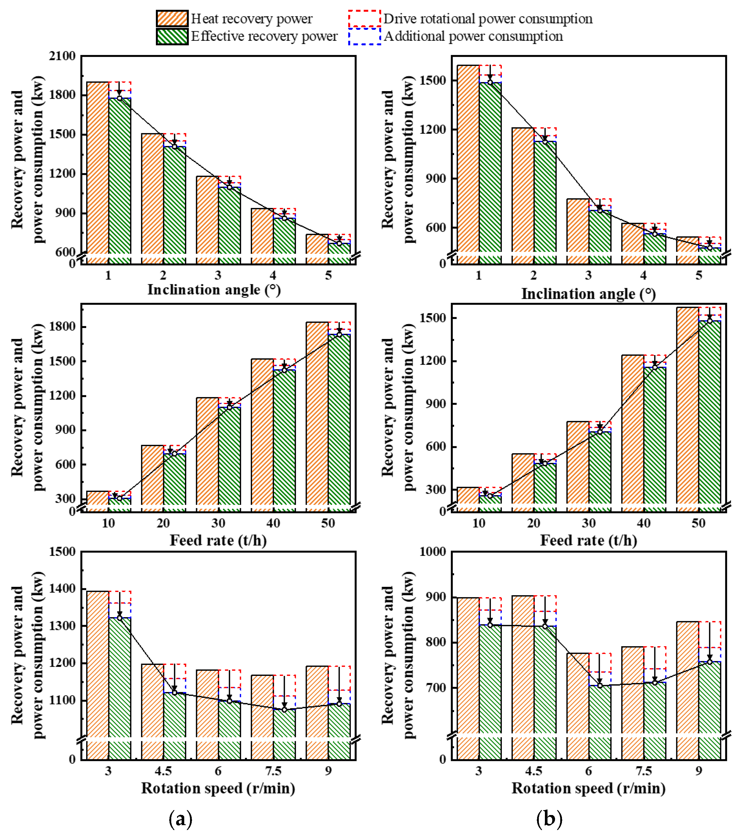
Across all operating conditions, the combined ratio of additional power consumption and drive power to heat recovery power consistently remained below 20% for both flight shapes. In the case of the separated flight, when operated at a low inclination angle or high feed rate, further reductions in inclination or increases in feed rate contributed more significantly to the improvement in effective heat recovery performance. Achieving the same cooling performance with this shape required drum lengths over 30% longer than those of the aligned flight, thereby resulting in a considerable increase in equipment construction cost.
In this study, the gas–solid heat exchange model was developed under the assumption of spatially uniform distribution of airborne particles. However, under practical operating conditions, the spatial distribution of particles can exhibit significant non-uniformity, leading to considerable variations in heat exchange efficiency. To address this limitation, future work should aim to extend the model’s dimensionality to more accurately capture gas–solid heat transfer under non-uniform particle distributions. It is also worth noting that in the current particle motion simulations, only the DEM was employed to predict particle behavior, while the interactions between the gas and solid phases were neglected. Such interactions can still influence particle dynamics to a certain extent. Therefore, future studies should incorporate a coupled gas–solid two-phase flow model to obtain a more accurate representation of the flow field. In addition, limited research has been conducted on the separated flight design, especially concerning the unresolved challenge of excessive particle migration induced by this configuration. Optimizing this configuration is expected to further improve the engineering viability and deployment potential of the novel flighted rotary drum in waste heat recovery systems.

Supplementary Materials

The following supporting information can be downloaded at https://www.mdpi.com/article/10.3390/pr13051594/s1, Figure S1: Comparison between experimental and simulated values; Figure S2: NPD distribution under different grid numbers; Figure S3. (a) Particle distribution cloud maps and (b) dynamic repose angle distributions under different particle diameter conditions. Table S1: Components of forces and torque acting on particle i. References cited in Supplementary Materials [41,42].

Author Contributions

Formal analysis, Y.H.; funding acquisition, Z.J. and D.E.; investigation, Y.H.; methodology, Y.H.; resources, Z.J.; software, Z.J. and D.E.; supervision, Z.J.; validation, D.E.; visualization, Y.H.; writing—original draft, Y.H.; writing—review and editing, Z.J. and D.E. All authors have read and agreed to the published version of the manuscript.

Funding

This work is supported by the Fundamental Research Funds for the Central Universities (grant No. FRF-BD-20-09A) and the National Natural Science Foundation of China (grant No. 52264042).

Data Availability Statement

The original contributions presented in this study are included in this article. Further inquiries can be directed to the corresponding author.

Conflicts of Interest

The authors declare that they have no known competing financial interests or personal relationships that could have appeared to influence the work reported in this paper.

References

  1. Li, Z.H.; Zhang, Y.Q.; Liu, Z.; Zhang, P.B.; Liu, Y.Q. Flow properties of two-component metallized pellets in waste heat recovery drum cooler. Process Saf. Environ. Prot. 2023, 177, 1477–1484. [Google Scholar] [CrossRef]
  2. Zhang, L.Y.; Zhang, P.B.; Yang, Z.Z.J.; Zhang, Y.Q.; Gao, H.B.; Gong, Z.X.; Liu, Y.Q.; Xiang, Z.Z.; Wang, Y.X. Optimizing waste heat recovery for hydrogen production: Modeling and simulation of ternary size metallic granule flow in a cooling cylinder. Int. J. Hydrogen Energy 2024, 91, 1306–1314. [Google Scholar] [CrossRef]
  3. Burgos-Florez, F.; Bula, A.; Marquez, J.; Ferrer, A.; Sanjuan, M. CFD-DEM Modeling and Simulation Coupled to a Global Thermodynamic Analysis Methodology for Evaluating Energy Performance: Biofertilizer Industry. Processes 2019, 7, 673. [Google Scholar] [CrossRef]
  4. Trojosky, M. Rotary drums for efficient drying and cooling. Dry. Technol. 2019, 37, 632–651. [Google Scholar] [CrossRef]
  5. Gao, H.B.; Liu, Y.Q.; Zheng, B.; Sun, P.; You, Y.Y.; Qi, X.N.; Mao, M.M.; Zhao, Q. Particles’ flow characteristics in a drum cooler with heat exchanger tubes: Simulation and comparison with traditional solution. J. Clean. Prod. 2020, 255, 120264. [Google Scholar] [CrossRef]
  6. Li, Y.H.; Liu, W.J.; Wang, W. Research on ash movement law of membrane bin drum slag cooler. Chem. Eng. Res. Des. 2023, 200, 202–210. [Google Scholar] [CrossRef]
  7. Witt, P.J.; Johnson, J.; Schwarz, M.P. An efficient method for computational flow-based simulation of heat transfer in a rotary kiln with pilot scale validation. Appl. Therm. Eng. 2022, 214, 118894. [Google Scholar] [CrossRef]
  8. Bisulandu, B.R.M.; Huchet, F. Rotary kiln process: An overview of physical mechanisms, models and applications. Appl. Therm. Eng. 2023, 221, 119637. [Google Scholar] [CrossRef]
  9. Portnikov, D.; Ziskind, G.; Kalman, H. Experimental and computational study of a flighted rotary drum cross-sectional characteristics. Powder Technol. 2022, 403, 117398. [Google Scholar] [CrossRef]
  10. Lomine, F.; Hellou, M.; Roques, Y. An analysis of optimal segmented flight design in a rotary dryer. Powder Technol. 2022, 407, 117594. [Google Scholar] [CrossRef]
  11. Zhou, Z.X.; Li, J.H.; Zhou, J.Z.; Li, S.Z.; Feng, J.X. Enhancing mixing of cohesive particles by baffles in a rotary drum. Particuology 2016, 25, 104–110. [Google Scholar] [CrossRef]
  12. Liao, H.B.; Lin, T.Q.; Gardoni, P.; Zhang, W.; Li, X.G.; Krolczyk, G.; Deng, L.; Li, Z.X. Molecular dynamics analysis of a flavoring drum combining numerical simulation and experimental evaluation. Eng. Anal. Bound. Elem. 2023, 146, 715–732. [Google Scholar] [CrossRef]
  13. Kozakovic, M.; Havlica, J.; Guen, L.L.; Parez, S.; Huchet, F. Recognition of the granular airborne portion in a flighted rotary drum. Powder Technol. 2023, 425, 118565. [Google Scholar] [CrossRef]
  14. Lange, A.; Meitzner, C.; Specht, E.; Kruggel-Emden, H. Exploring transverse particle motion in rotary drums: DEM analysis of the influence of cross-shaped internals on material transport. Powder Technol. 2024, 443, 119907. [Google Scholar] [CrossRef]
  15. Seidenbecher, J.; Herz, F.; Specht, E.; Dieguez-Alonso, A. Contact heat transfer analysis in flighted rotary drums. Therm. Sci. Eng. Prog. 2024, 47, 102265. [Google Scholar] [CrossRef]
  16. Xie, Q.; Chen, Z.B.; Hou, Q.F.; Yu, A.B.; Yang, R.Y. DEM investigation of heat transfer in a drum mixer with lifters. Powder Technol. 2017, 314, 175–181. [Google Scholar] [CrossRef]
  17. Silveira, J.C.; Brandao, R.J.; Lima, R.M.; Machado, M.V.C.; Barrozo, M.A.S.; Duarte, C.R. A fluid dynamic study of the active phase behavior in a rotary drum with flights of two and three segments. Powder Technol. 2020, 368, 297–307. [Google Scholar] [CrossRef]
  18. Karali, M.A.; Sunkara, K.R.; Herz, F.; Specht, E. Experimental analysis of a flighted rotary drum to assess the optimum loading. Chem. Eng. Sci. 2015, 138, 772–779. [Google Scholar] [CrossRef]
  19. Karali, M.A.; Herz, F.; Specht, E.; Mallmann, J. Comparison of image analysis methods to determine the optimum loading of flighted rotary drums. Powder Technol. 2016, 291, 147–153. [Google Scholar] [CrossRef]
  20. Karali, M.A.; Specht, E.; Herz, F.; Mallmann, J. Different camera and light positions to facilitate image analysis processing in rotary drums studies. Powder Technol. 2017, 306, 55–60. [Google Scholar] [CrossRef]
  21. Karali, M.A.; Specht, E.; Herz, F.; Mallmann, J.; Refaey, H.A. Unloading characteristics of flights in a flighted rotary drum operated at optimum loading. Powder Technol. 2018, 333, 347–352. [Google Scholar] [CrossRef]
  22. Ajayi, O.O.; Sheehan, M.E. Design loading of free flowing and cohesive solids in flighted rotary dryers. Chem. Eng. Sci. 2012, 73, 400–411. [Google Scholar] [CrossRef]
  23. Priessen, J.; Barths, F.; Behrens, M.; Schultz, H.J. The length of axially segmented lifters in flighted rotary drums: Influence on solid transport. Dry. Technol. 2021, 40, 3003–3020. [Google Scholar] [CrossRef]
  24. Silveira, J.C.; Lima, R.M.; Brandao, R.J.; Duarte, C.R.; Barrozo, M.A.S. A study of the design and arrangement of flights in a rotary drum. Powder Technol. 2022, 395, 195–206. [Google Scholar] [CrossRef]
  25. Lacombe, E.; Marchand, M.; Dupont, C.; Marechal, D.; Melkior, T. Residence time distribution of wood chips in a semi-industrial multiple hearth furnace using RFID tracers. Particuology 2024, 91, 268–279. [Google Scholar] [CrossRef]
  26. Miao, Q.H.; Zhu, W.C.; Wang, J.X.; Huang, P.; Hu, C.B.; Ge, Y. Application of the combination on data-driven and discrete element model: Particle segregation prediction and classification in rotary drums. Chem. Eng. Res. Des. 2023, 200, 456–468. [Google Scholar] [CrossRef]
  27. Brazhenko, V.; Mochalin, I. Terminal velocity and drag coefficient of a smooth steel sphere moving in the water-filled vertical and inclined glass pipe (Newton regime). Powder Technol. 2024, 446, 120120. [Google Scholar] [CrossRef]
  28. Bongo Njeng, A.S.; Vitu, S.; Clausse, M.; Dirion, J.L.; Debacq, M. Effect of lifter shape and operating parameters on the flow of materials in a pilot rotary kiln: Part III. Up-scaling considerations and segregation analysis. Powder Technol. 2016, 297, 415–428. [Google Scholar] [CrossRef]
  29. Zhang, L.; Weigler, F.; Idakiev, V.; Jiang, Z.; Mörl, L.; Mellmann, J.; Tsotsas, E. Experimental study of the particle motion in flighted rotating drums by means of Magnetic Particle Tracking. Powder Technol. 2018, 339, 817–826. [Google Scholar] [CrossRef]
  30. Zhang, L.; Jiang, Z.; Weigler, F.; Herz, F.; Mellmann, J.; Tsotsas, E. PTV measurement and DEM simulation of the particle motion in a flighted rotating drum. Powder Technol. 2020, 363, 23–37. [Google Scholar] [CrossRef]
  31. Zhu, X.; Xie, L.X.; Xu, S.C.; Zhang, W. DEM Simulation of a Rotary Drum with Inclined Flights Using the Response Surface Methodology. Processes 2023, 11, 1363. [Google Scholar] [CrossRef]
  32. Jian, Q.S.; Gu, H.L.; Wang, K.G.; Wang, S.; Zhan, M.X.; Wang, J.Q.; Ji, L.J.; Chi, Z.H.; Zhang, G.X. Numerical study of particle behaviours and heat transfer in a complex rotary kiln. Particuology 2024, 92, 81–94. [Google Scholar] [CrossRef]
  33. Xu, L.; Wu, X.K.; Wang, S.; Bao, S.Y. Multi-level coarse-grained discrete element method modeling of cylinder particle flow in a rotating drum. Particuology 2024, 88, 218–238. [Google Scholar] [CrossRef]
  34. Tsuji, Y.; Tanaka, T.; Ishida, T. Lagrangian numerical simulation of plug flow of cohesionless particles in a horizontal pipe. Powder Technol. 1992, 71, 239–250. [Google Scholar] [CrossRef]
  35. Renzo, A.D.; Di-Maio, F.P. Comparison of contact-force models for the simulation of collisions in DEM-based granular flow codes. Chem. Eng. Sci. 2004, 59, 525–541. [Google Scholar] [CrossRef]
  36. Feng, Y.H.; Zhang, Z.; Qiu, L.; Zhang, X.X. Heat recovery process modelling of semi-molten blast furnace slag in a moving bed using XDEM. Energy 2019, 186, 115876. [Google Scholar] [CrossRef]
  37. Delele, M.A.; Weigler, F.; Franke, G.; Mellmann, J. Studying the solids and fluid flow behavior in rotary drums based on a multiphase CFD model. Powder Technol. 2016, 292, 260–271. [Google Scholar] [CrossRef]
  38. Ma, J.; Lei, X.L.; Ma, R.C. Parameters Optimization of Rotary Drying by Uniform Design. Appl. Mech. Mater. 2014, 448–453, 3523–3531. [Google Scholar] [CrossRef]
  39. Mahdavy, S.; Norouzi, H.R.; Jordan, C.; Haddadi, B.; Harasek, M. Residence time distribution of non-spherical particles in a continuous rotary drum. Processes 2022, 10, 1069. [Google Scholar] [CrossRef]
  40. Li, Z.; Zhang, X.R.; Lai, N.C.; Jiang, Z.Y.; Li, J.Z. A novel process for coke wastewater gasification quenching: Energy and exergy analysis. Appl. Therm. Eng. 2021, 191, 116863. [Google Scholar] [CrossRef]
  41. Lauredan, L.G.; Florian, H.; Jean, D. A wall heat transfer correlation for the baffled-rotary kilns with secondary air flow and recycled materials inlet. Exp. Therm. Fluid Sci. 2014, 54, 110–116. [Google Scholar] [CrossRef]
  42. Wu, W.N.; Liu, X.Y.; Zhang, R.; Hu, Z. DEM investigation of the power draw for material movement in rotary drums with axis offset. Chem. Eng. Res. Des. 2019, 144, 310–317. [Google Scholar] [CrossRef]
Figure 1. (a) Schematic of the RDF system (underlined values indicate baseline operating conditions); (b) particle distribution regions; and (c) geometry of the flight shape.
Processes 13 01594 g001
Figure 2. (a) Simplified schematic of the RDF operating principle; (b) illustration of gas–solid heat exchange and thermal loss to the environment.
Processes 13 01594 g002
Figure 3. Comparison of simulated results with experimental data.
Processes 13 01594 g003
Figure 4. Effect of (a) Inclination angle, (b) feed rate, and (c) rotation speed on particle distribution patterns in the radial and axial directions under aligned flights.
Processes 13 01594 g004
Figure 5. Effect of (a) Inclination angle, (b) feed rate, and (c) rotation speed on particle distribution patterns in the radial and axial directions under separated flights.
Processes 13 01594 g005
Figure 6. Particle motion characteristics under various operating parameters: (a) axial particle velocity; (b) filling degree and reflux ratio.
Processes 13 01594 g006
Figure 7. Particle residence time distributions under different operating parameters: (a) aligned flight; (b) separated flight.
Processes 13 01594 g007
Figure 8. Distributions of EHER and NPD under varying (a) inclination angle, (b) feed rate, and (c) rotation speed conditions.
Processes 13 01594 g008
Figure 9. Gas–solid temperature distribution and exergy efficiency under different operating parameters: (a) aligned flight; (b) separated flight.
Processes 13 01594 g009
Figure 10. Heat recovery power and system power consumption under different operating parameters: (a) aligned flight; (b) separated flight.
Processes 13 01594 g010
Figure 11. Effect of operating parameters on process cost and power requirements for achieving the same cooling effect: (a) required drum length; (b) recovered and consumed power.
Processes 13 01594 g011
Table 1. Physical properties and parameters used in DEM simulations.
Parameter (Unit)Value
Particle diameter (mm)12
Density (kg/m3)2800
Shear modulus (Pa)5.3 × 10⁹
Poisson ratio (-)0.2
Restitution for P-P (-)0.25
Static friction for P-P (-)0.41
Rolling friction for P-P (-)0.08
Restitution for P-W (-)0.2
Static friction for P-W (-)0.36
Rolling friction for P-W (-)0.1
Note: P-P represents particle–particle; P-W represents particle–wall.
Table 2. DEM calculation condition setting.
ParametersBase ValueVariation Value
Inclination angle (°)31, 2, 4, 5
Feed rate (t/h)3010, 20, 40, 50
Rotation speed (r/min)63, 4.5, 7.5, 9
Disclaimer/Publisher’s Note: The statements, opinions and data contained in all publications are solely those of the individual author(s) and contributor(s) and not of MDPI and/or the editor(s). MDPI and/or the editor(s) disclaim responsibility for any injury to people or property resulting from any ideas, methods, instructions or products referred to in the content.

