
Numerical Simulation and Intelligent Prediction of Effects of Primary Air Proportion and Moisture Content on MSW Incineration

Abstract
1. Introduction
2. Methods
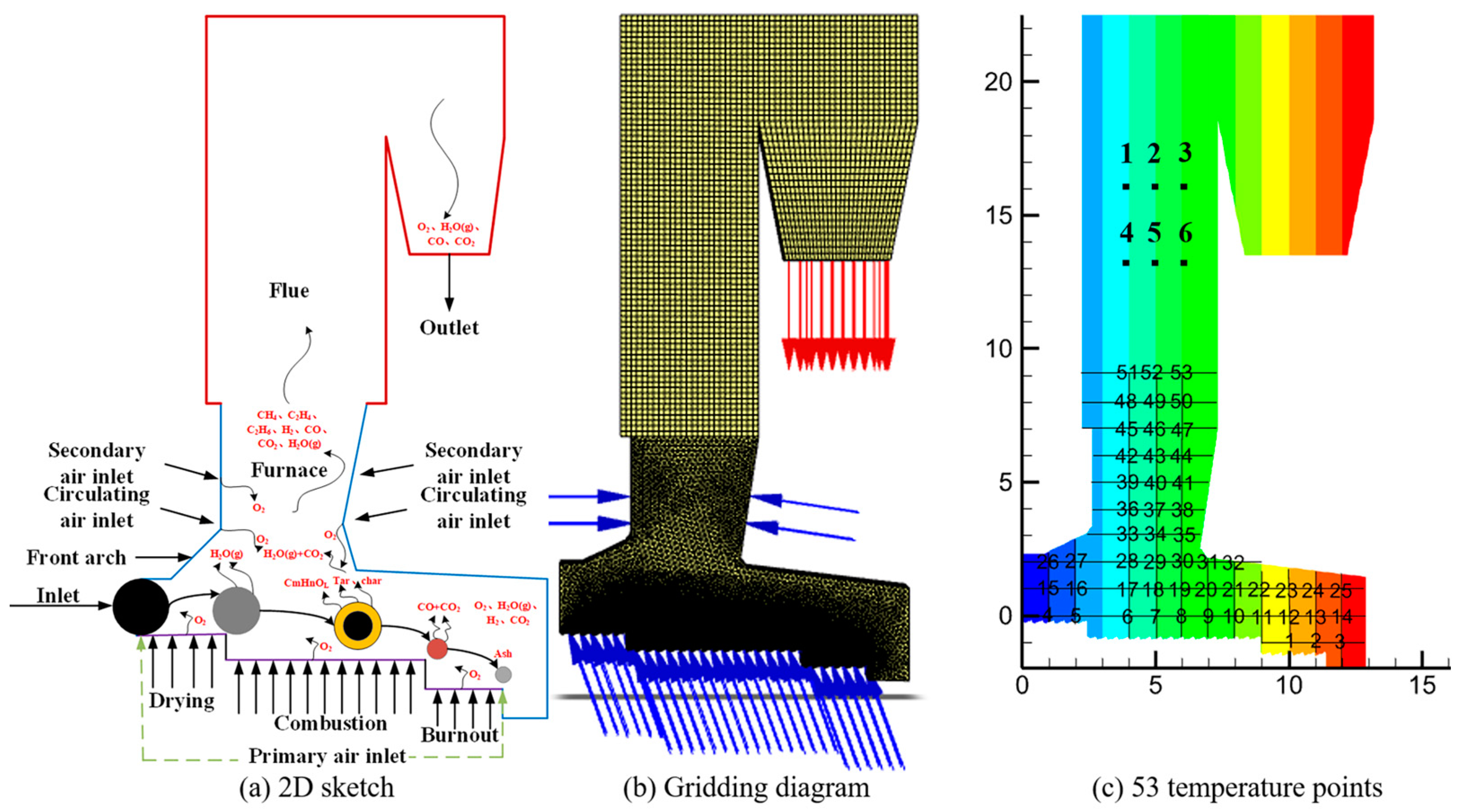
2.1. Physical Model
2.2. Governing Equation
2.3. Boundary Conditions
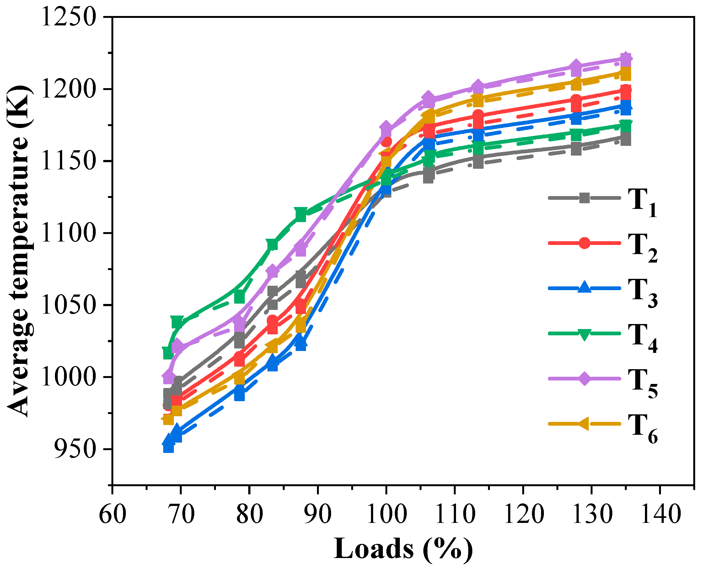
2.4. Validation
3. Results and Discussion
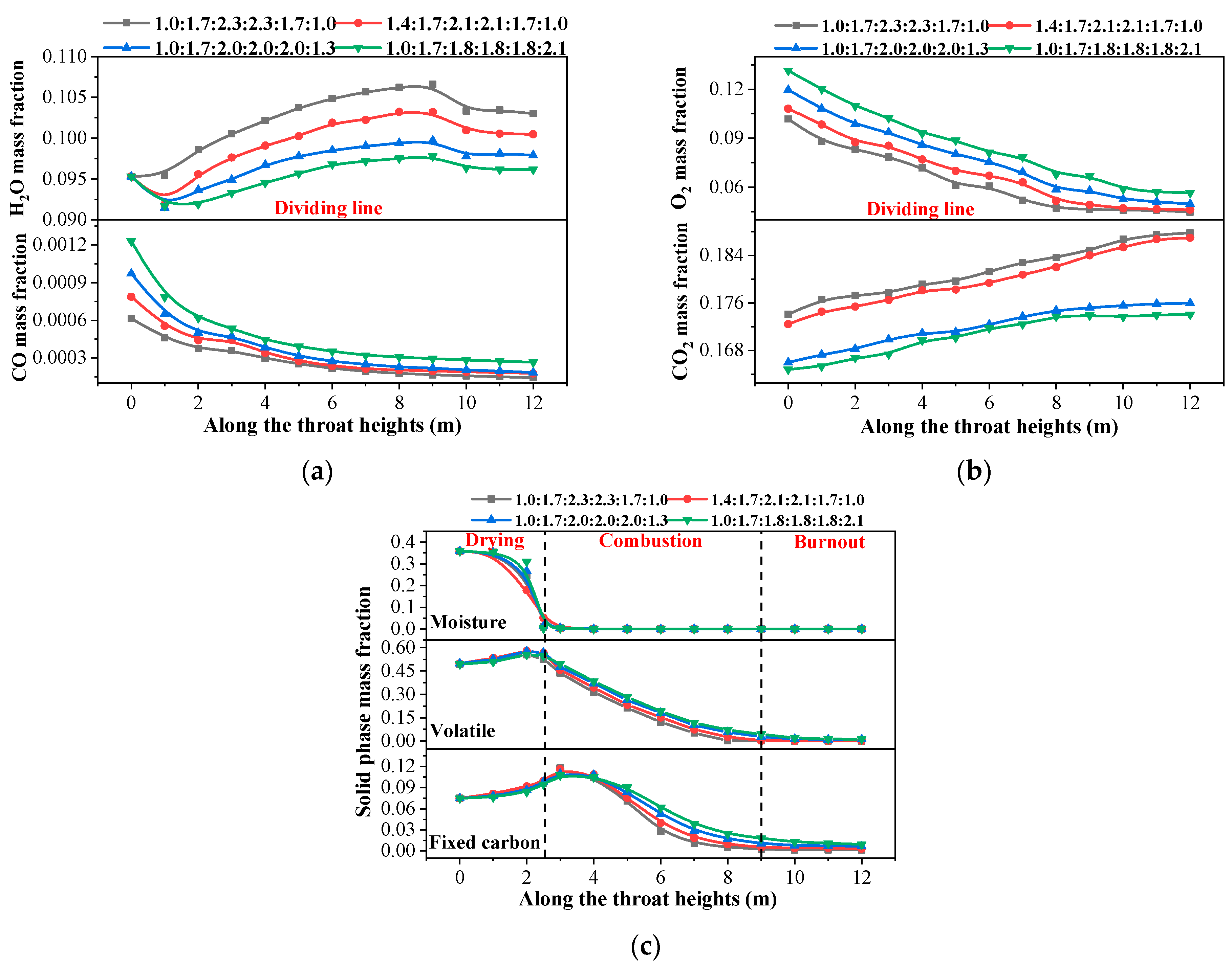
3.1. Effects of Primary Air Proportion on MSW Incineration Status
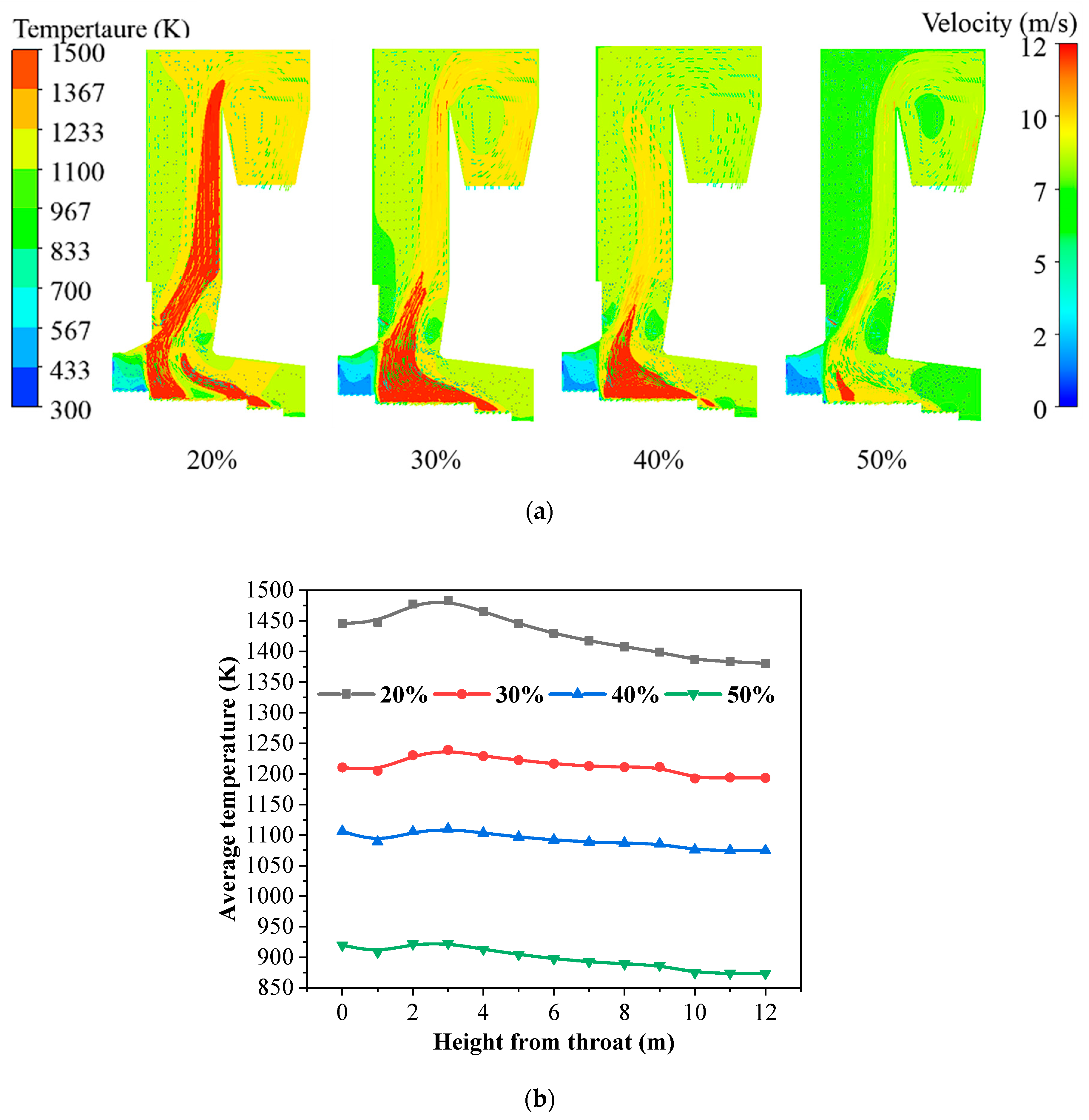
3.2. Effects of Moisture Content on MSW Incineration Status
3.3. BP Neural Network Model of Flue Gas Temperature Based on Time Domain Input
4. Conclusions
- Increasing the air proportion in the drying section accelerates the evaporation of moisture. In contrast, decreasing the air proportion in the combustion section lowers the average temperature by 59 K and extends the distance required for complete combustion by 0.5–2 m. Meanwhile, increasing the air proportion in the burnout section promotes the further combustion of unburned volatiles and fixed carbon.
- Higher moisture content in MSW reduces the average temperature and increases incomplete combustion, significantly raising CO emissions (by 79% at 50% moisture compared to 20%). The optimal combination parameters are as follows: the primary air proportion is 1:1.7:2.3:2.3:1.7:1, and M = 30%.
- A dynamic BP neural network model was successfully developed to predict the relationship between furnace temperature and grate movement. The model demonstrated high accuracy, with a minimum MSE of 1.629% and 1.635% during training and an MAE of approximately 0.069% and 0.068%. This model effectively captures nonlinear relationships and maintains high prediction accuracy under new operating conditions.
- The novelty of this study lies in the integrated approach combining computational simulation and on-site data to optimize incineration parameters and the application of artificial intelligence for the real-time prediction of combustion trends. Future work will focus on integrating advanced AI technologies with incinerator systems to dynamically adjust operational parameters based on actual conditions, further improving the efficiency and environmental performance of MSW incineration.
Author Contributions
Funding
Data Availability Statement
Conflicts of Interest
References
- Wikurendra, E.A.; Csonka, A.; Nagy, I.; Nurika, G. Urbanization and Benefit of Integration Circular Economy into Waste Management in Indonesia: A Review. Circ. Econ. Sustain. 2024, 4, 1219–1248. [Google Scholar] [CrossRef]
- Zeng, Y.; Filimonau, V.; Wang, L.; Zhong, L. The impact of tourism on municipal solid waste generation in China. J. Clean. Prod. 2023, 427, 139255. [Google Scholar]
- Lu, J.-W.; Zhang, S.; Hai, J.; Lei, M. Status and perspectives of municipal solid waste incineration in China: A comparison with developed regions. Waste Manag. 2017, 69, 170–186. [Google Scholar] [CrossRef]
- Zhao, J.; Ma, L.; Zayed, M.E.; Elsheikh, A.H.; Li, W.; Yan, Q.; Wang, J. Industrial reheating furnaces: A review of energy efficiency assessments, waste heat recovery potentials, heating process characteristics and perspectives for steel industry. Process Saf. Environ. Prot. 2021, 147, 1209–1228. [Google Scholar] [CrossRef]
- Li, J.; An, D.; Shi, Y.; Bai, R.; Du, S. A review of the physical and chemical characteristics and energy-recovery potential of municipal solid waste in China. Energies 2024, 17, 491. [Google Scholar] [CrossRef]
- Sekar, M.; Ponnusamy, V.K.; Pugazhendhi, A.; Nizetic, S.; Praveenkumar, T.R. Production and utilization of pyrolysis oil from solidplastic wastes: A review on pyrolysis process and influence of reactors design. J. Environ. Manag. 2022, 302 Pt B, 114046. [Google Scholar] [CrossRef]
- Dashti, A.; Noushabadi, A.S.; Asadi, J.; Raji, M.; Chofreh, A.G.; Klemeš, J.J.; Mohammadi, A.H. Review of higher heating value of municipal solid waste based on analysis and smart modelling. Renew. Sustain. Energy Rev. 2021, 151, 111591. [Google Scholar] [CrossRef]
- Liu, J.; Xie, Z.; Guo, B.; Xu, Y.; Wang, Q.; Guo, X.; Bai, L.; Long, J. The effect of air distribution on the characteristics of waste combustion and NO generation in a grate incinerator. J. Energy Inst. 2024, 117, 101827. [Google Scholar] [CrossRef]
- Jiang, M.; Lai, A.C.; Law, A.W.-K. Solid waste incineration modelling for advanced moving grate incinerators. Sustainability 2020, 12, 8007. [Google Scholar] [CrossRef]
- Marias, F.; Benzaoui, A.; Vaxelaire, J.; Gelix, F.; Nicol, F. Fate of Nitrogen during Fluidized Incineration of Sewage Sludge. Estimation of NO and N2O Content in the Exhaust Gas. Energy Fuels 2015, 29, 4534–4548. [Google Scholar] [CrossRef]
- Mungyeko Bisulandu, B.J.R.; Marias, F. Modeling of the Thermochemical Conversion of Biomass in Cement Rotary Kiln. Waste Biomass Valorizat. 2020, 12, 1005–1024. [Google Scholar] [CrossRef]
- Wang Ca Chen, M.; Zhao, P.; Zhou, L.; Hou, Y.; Zhang, J.; Lyu, Q.; Che, D. Investigation on Co-combustion characteristics and NOx emissions of coal and municipal sludge in a tangentially fired boiler. Fuel 2023, 340, 127608. [Google Scholar] [CrossRef]
- Jia, M.; Wang, X.; Zhang, W.; Song, Q.; Qian, B.; Ye, Y.; Xu, K.; Wang, X. Prediction of CO/NOx emissions and the smoldering characteristic of sewage sludge based on back propagation neural network. Environ. Pollut. 2024, 342, 123049. [Google Scholar] [CrossRef] [PubMed]
- Zhuo, X.; Li, M.; Cheng, Q.; Luo, Z. Experimental studies on the combustion characteristics of multisource organic solid waste for collaborative disposal using municipal solid waste incinerators. ACS Omega 2024, 9, 2911–2919. [Google Scholar] [CrossRef]
- Cao, H.; Jin, Y.; Song, X.; Wang, Z.; Liu, B.; Wu, Y. Computational fluid dynamics simulation of combustion and selective non-catalytic reduction in a 750 T/D waste incinerator. Processes 2023, 11, 2790. [Google Scholar] [CrossRef]
- Zhang, J.; Li, T.; Ström, H.; Løvås, T. Computationally efficient coarse-graining XDEM/CFD modeling of fixed-bed combustion of biomass. Combust. Flame 2022, 238, 111876. [Google Scholar] [CrossRef]
- Hu, C.; Luo, K.; Zhou, M.; Lin, J.; Kong, D.; Fan, J. Influences of secondary gas injection pattern on fluidized bed combustion process: A CFD-DEM study. Fuel 2020, 268, 117314. [Google Scholar] [CrossRef]
- Yang, Y.; Goh, Y.; Zakaria, R.; Nasserzadeh, V.; Swithenbank, J. Mathematical modelling of MSW incineration on a travelling bed. Waste Manag. 2002, 22, 369–380. [Google Scholar] [CrossRef]
- Marias, F.; Roustan, H.; Pichat, A. Modelling of a rotary kiln for the pyrolysis of aluminium waste. Chem. Eng. Sci. 2005, 60, 4609–4622. [Google Scholar] [CrossRef]
- Sun, R.; Ismail, T.M.; Ren, X.; Abd El-Salam, M. Influence of simulated MSW sizes on the combustion process in a fixed bed: CFD and experimental approaches. Waste Manag. 2016, 49, 272–286. [Google Scholar] [CrossRef]
- Hu, Z.; Jiang, E.; Ma, X. Numerical simulation on NOX emissions in a municipal solid waste incinerator. J. Clean. Prod. 2019, 233, 650–664. [Google Scholar] [CrossRef]
- Qi, X.; Ma, X.; Yu, Z.; Huang, Z.; Teng, W. Numerical simulation of municipal waste and food digestate blending combustion and NOx reduction under oxygen-enriched atmospheres. Fuel 2023, 345, 128115. [Google Scholar] [CrossRef]
- Li, Z.; Fan, T.W.; Lun, M.S.; Li, Q. Optimization of municipal solid waste incineration for low-NO(x) emissions through numerical simulation. Sci. Rep. 2024, 14, 19309. [Google Scholar] [CrossRef] [PubMed]
- Gu, T.; Ma, W.; Berning, T.; Guo, Z.; Andersson, R.; Yin, C. Advanced simulation of a 750 t/d municipal solid waste grate boiler to better accommodate feedstock changes due to waste classification. Energy 2022, 254, 124338. [Google Scholar] [CrossRef]
- Tang, J.; Zhuang, J.; Aljerf, L.; Xia, H.; Wang, T.; Gao, B. Numerical simulation modelling on whole municipal solid waste incineration process by coupling multiple software for the analysis of grate speed and air volume ratio. Process Saf. Environ. Prot. 2023, 176, 506–527. [Google Scholar] [CrossRef]
- Liang, L.; Sun, R.; Fei, J.; Wu, S.; Liu, X.; Dai, K.; Yao, N. Experimental study on effects of moisture content on combustion characteristics of simulated municipal solid wastes in a fixed bed. Bioresour. Technol. 2008, 99, 7238–7246. [Google Scholar] [CrossRef]
- Magnanelli, E.; Tranås, O.L.; Carlsson, P.; Mosby, J.; Becidan, M. Dynamic modeling of municipal solid waste incineration. Energy 2020, 209, 118426. [Google Scholar] [CrossRef]
- Chen, J.; Wang, M.; Li, D.; Wang, B.; Michael, Z.; Lapatsin, S.; Yu, G. Simulation of gasification characteristics from municipal solid waste under different moisture content. Chem. Ind. Eng. Prog. 2024, 43, 4900–4908. [Google Scholar]
- Wu, S.; Dang, W.; Shi, X.; Li, W.; Yuan, S.; Fan, Y. Whole process simulation of MSW gasification and melting system based on Aspen Plus. J. Environ. Eng. Technol. 2024, 14, 184–193. [Google Scholar]
- Hu, Q.-X.; Long, J.-S.; Wang, S.-K.; He, J.-J.; Bai, L.; Du, H.-L.; Huang, Q.X. A novel time-span input neural network for accurate municipal solid waste incineration boiler steam temperature prediction. J. Zhejiang Univ.-Sci. A 2021, 22, 777–791. [Google Scholar] [CrossRef]
- Liu, Z. Feasibility Study on Evaporation Prediction of Waste Incinerator. Energy Sav. Environ. Prot. 2021, 6, 61–62. [Google Scholar]
- Li, H.; Xu, Q.; Xiao, K.; Yang, J.; Liang, S.; Hu, J.; Hou, H.; Liu, B. Predicting the higher heating value of syngas pyrolyzed from sewage sludge using an artificial neural network. Environ. Sci. Pollut. Res. 2020, 27, 785–797. [Google Scholar] [CrossRef] [PubMed]
- Gu, C.; Wang, X.; Song, Q.; Li, H.; Qiao, Y. Prediction of Distribution Law of Solid Waste Pyrolysis Products Based on BP Neural Network. J. Combust. Sci. Technol. 2022, 28, 133–140. [Google Scholar]
- Xing, J.; Luo, K.; Wang, H.; Gao, Z.; Fan, J. A comprehensive study on estimating higher heating value of biomass from proximate and ultimate analysis with machine learning approaches. Energy 2019, 188, 116077. [Google Scholar] [CrossRef]
- Praveenkumar, T.R.; Alahmadi, T.A.; Salmen, S.H.; Verma, T.N.; Gupta, K.K.; Gavurová, B.; Sekar, M. Impact of sludge density and viscosity on continuous stirred tank reactor performance in wastewater treatment by numerical modelling. J. Taiwan Inst. Chem. Eng. 2025, 166, 105368. [Google Scholar]
- Xia, Z.; Long, J.; Yan, S.; Bai, L.; Du, H.; Chen, C. Two-fluid simulation of moving grate waste incinerator: Comparison of 2D and 3D bed models. Energy 2021, 216, 119257. [Google Scholar] [CrossRef]
- Ergun, S. Fluid Flow through Packed Columns. Chem. Eng. Prog. 1952, 48, 89–94. [Google Scholar]
- Gunn, D.J. Transfer of heat or mass to particles in fixed and fluidised beds. Int. J. Heat Mass Transf. 1978, 21, 467–476. [Google Scholar] [CrossRef]
- Goldberg, U. A Realizable Version of the k-ωTurbulence Model. Stud. Eng. Technol. 2017, 4, 1–24. [Google Scholar] [CrossRef]
- Asllanaj, F.; Contassot-Vivier, S.; Fraga, G.C.; França, F.H.; Da Fonseca, R.J. New gas radiation model of high accuracy based on the principle of weighted sum of gray gases. J. Quant. Spectrosc. Radiat. Transf. 2024, 315, 108887. [Google Scholar] [CrossRef]
- Zimont, V.L.; Trushin, Y.M. Total combustion kinetics of hydrocarbon fuels. Combust. Explos. Shock. Waves 1969, 5, 391–394. [Google Scholar] [CrossRef]
- Kaushal, P.; Pröll, T.; Hofbauer, H. Model development and validation: Co-combustion of residual char, gases and volatile fuels in the fast fluidized combustion chamber of a dual fluidized bed biomass gasifier. Fuel 2007, 86, 2687–2695. [Google Scholar] [CrossRef]
- Vilienskii, T.; Hezmalian, D. Dynamics of the combustion of pulverized fuel. Energia 1978, 11, 246–251. [Google Scholar]
- Dryer, F.L.; Glassman, I. High-Temperature Oxidation of CO and CH4; Elsevier: Amsterdam, The Netherlands, 1973; Volume 14, pp. 987–1003. [Google Scholar]
- Zhang, Y.; Shi, Z.; Hou, H. Impact of Air Excess Ratio and Preheating on Temperature Distribution in Vertical Cylindrical Tube Furnace; IEEE: Piscataway, NJ, USA, 2012; pp. 1–4. [Google Scholar]
- Ma, T.; Zhou, H.; Xu, F.; Chen, D.; Qian, K.; Yin, L. Numerical simulation and intelligent prediction of a 500 t/d municipal solid waste incinerator. Energy 2024, 312, 133646. [Google Scholar] [CrossRef]


| Type | Industrial Analysis (%) | Qnet,ar MJ·kg −1 | Elemental Analysis (%) | |||||||
|---|---|---|---|---|---|---|---|---|---|---|
| Mar | Aar | Var | FCar | Cd | Hd | Od | Nd | Sd | ||
| MSW | 35.00 | 8.10 | 49.40 | 7.50 | 10.00 | 45.80 | 6.37 | 34.69 | 1.21 | 0.03 |
| Name | Equation | No. |
|---|---|---|
| Gas phase [35] | (1) | |
| (2) | ||
| (3) | ||
| (4) | ||
| Solid phase [36] | (5) | |
| (6) | ||
| (7) | ||
| (8) | ||
| Gas-phase turbulence [18] | (9) | |
| (10) |
| Reaction | A/s−1 | E/J·kmol−1 | Reference |
|---|---|---|---|
| CH4 + 1.5O2→CO + 2H2O | 1.69 × 10⁹ | 2.84 × 10⁷ | [11] |
| C2H4 + 2O2→2CO + 2H2O | 1.6 × 10¹⁰ | 2 × 10⁸ | [41] |
| C2H6 + 2.5O2→2CO + 3H2O | 1 × 10¹² | 1.73 × 10⁸ | [42] |
| 2H2 + O2→2H2O | 7.97 × 10¹⁴ | 9.65 × 10⁷ | [43] |
| 2CO + O2→2CO2 | 2.67 × 10⁸ | 1.67 × 10⁸ | [44] |
| C5.71H9.25O0.51 + 4.9125O2→5.71CO + 4.625H2O | 2.39 × 10¹³ | 1.7 × 10⁸ | Experimental |
Disclaimer/Publisher’s Note: The statements, opinions and data contained in all publications are solely those of the individual author(s) and contributor(s) and not of MDPI and/or the editor(s). MDPI and/or the editor(s) disclaim responsibility for any injury to people or property resulting from any ideas, methods, instructions or products referred to in the content. |
© 2025 by the authors. Licensee MDPI, Basel, Switzerland. This article is an open access article distributed under the terms and conditions of the Creative Commons Attribution (CC BY) license (https://creativecommons.org/licenses/by/4.0/).
Share and Cite
Chen, S.; Xu, F.; Chen, Y.; Yin, L. Numerical Simulation and Intelligent Prediction of Effects of Primary Air Proportion and Moisture Content on MSW Incineration. Processes 2025, 13, 1479. https://doi.org/10.3390/pr13051479
Chen S, Xu F, Chen Y, Yin L. Numerical Simulation and Intelligent Prediction of Effects of Primary Air Proportion and Moisture Content on MSW Incineration. Processes. 2025; 13(5):1479. https://doi.org/10.3390/pr13051479
Chicago/Turabian StyleChen, Shanping, Fang Xu, Yong Chen, and Lijie Yin. 2025. "Numerical Simulation and Intelligent Prediction of Effects of Primary Air Proportion and Moisture Content on MSW Incineration" Processes 13, no. 5: 1479. https://doi.org/10.3390/pr13051479
APA StyleChen, S., Xu, F., Chen, Y., & Yin, L. (2025). Numerical Simulation and Intelligent Prediction of Effects of Primary Air Proportion and Moisture Content on MSW Incineration. Processes, 13(5), 1479. https://doi.org/10.3390/pr13051479