Article

Research on Electromagnetic Control Technology for the Roll Profile of Wide-Width Electrode Roll Press Rolls

1
National Engineering Research Center for Equipment and Technology of Cold Strip Rolling, Yanshan University, Qinhuangdao 066004, China
2
CISDI Thermal & Enviromental Engineering Co., Ltd., Chongqing 401122, China
3
Xingtai Naknor Technology Co., Ltd., Xingtai 054000, China
*
Author to whom correspondence should be addressed.
Processes 2025, 13(5), 1448; https://doi.org/10.3390/pr13051448
Submission received: 17 March 2025 / Revised: 1 May 2025 / Accepted: 6 May 2025 / Published: 9 May 2025
(This article belongs to the Section Energy Systems)

Abstract

:
To address the challenge of transverse thickness consistency in wide-width electrode calendering, this study developed a flexible roll profile regulation technology based on electromagnetic induction heating. An axisymmetric electromagnetic–thermal–structural coupling finite element model is established and validated on a self-built experimental platform. Systematic simulations were conducted to investigate the influence of equivalent current density Js, current frequency f, and coil turn n on the roll temperature and roll profile. The maximum temperature of the roll’s inner bore and the roll crown exhibit a positive correlation with Js, f, and n. A cyclic heating strategy was developed to control and stabilize the roll profile. The stable crown CW shows linear correlation with heating durations t1 and a nonlinear trend with Js. Under fixed Js and t1, further optimization of duty cycle and cooling conditions enables long-term stabilization of the roll profile.

1. Introduction

Vehicle electrification has become an important direction for the automotive industry to address the global climate and energy crisis. Lithium-ion batteries have emerged as the predominant power source for electric vehicles (EVs) owing to their exceptional energy density, low self-discharge characteristics, and superior cycle life performance [1,2]. The calendering process plays a pivotal role in Li-ion battery manufacturing, in which the as-coated porous electrode is compacted under the pressure of a pair of counter-rotating rolls [3,4]. By enhancing the electrode areal density, strengthening the interfacial adhesion between the active material coating and the metallic current collector, optimizing the pore structure and increasing the ionic conductivity, calendering enhances the battery’s capacity, safety, and longevity, which are critical for meeting the increasing demands of modern battery applications [5,6,7,8,9].
Thickness uniformity control is a critical quality metric in the calendering process. Inadequate thickness uniformity induces heterogeneous current distribution and localized stress concentrations, resulting in inconsistent cell performance and consequent degradation of battery pack efficiency and cycle life [10]. Driven by the EV industry’s demands for cost reduction and efficiency enhancement, electrode calendering is advancing towards ultra-wide formats, which pose significant challenges in controlling transverse thickness uniformity under ±2 μm [11]. Wider electrodes require longer rollers and higher calendering forces, which significantly increase roll deflection and consequently exacerbate edge thickness reduction. Current roll bending adjustment methods are demonstrating growing limitations, and grinding a certain roll camber or an initial crown is also applied to enhance the effectiveness of roll bending in ultra-wide format electrode calendering [12,13]. However, the fixed ground roll profile can only accommodate electrodes within specific width ranges, which fails to satisfy the multi-width production capability essential for flexible manufacturing.
Roll profile control technologies in strip rolling, including roll traverse shifting systems (HC, CVC) and hydraulic bulge mechanisms (VC, DSR), are not suitable for electrode calendering due to the extremely thin thickness and the coating delamination tendency [14,15,16,17]. Thermal bulging technology is also widely adopted by heating or cooling the roll segmentally to realize roll profile flexible control [18,19]. Du et al. [20] proposed the roll profile electromagnetic control technology (RPECT), which adjusts the roll profile by inductively heating an electromagnetic stick inside the roll, and converting the energy of induction heating into a thermal–mechanical hybrid power source based on the thermally driven and internal constraint mechanism. The influence of electromagnetic parameters on the control ability of the roll profile was thoroughly analyzed [21]. Liu et al. [22] built an RPECT experimental platform and verified the feasibility of roll profile electromagnetic control technology. Feng et al. [23] simulated the roll profile adjustment ability for a ϕ1400 × 1420 mm-sleeved backup roll and verified the effectiveness of roll profile electromagnetic control technology for large-diameter rollers. Liu [24] investigated the influence of roll diameter on the capability of the roll profile control capability of RPECT, which demonstrated that under identical induction heating parameters, the crown variation of a ϕ 350 mm roll within 100 s is approximately one-fifth that of a ϕ 190 mm roll, accompanied by a significant reduction in contact stress between the electromagnetic rod and the roller, indicating diminished force-driven effects.
According to current research on electromagnetic roll profile control technology, primarily RPECT, it is technically feasible to adjust the profile of large-diameter rolls using electromagnetic induction heating, but prolonged heating duration and thermal inertia may result in slower response characteristics. Electrode calendering is usually characterized by infrequent specification changes, which means the roll profile does not need to be adjusted frequently. Therefore, roll profile control based on electromagnetic induction heating is feasible for calendering mills. Moreover, the roll thermal crown can be rapidly established during the initial commissioning phase of new rolls, thereby significantly reducing prolonged thickness deviations caused by the transitional period of natural thermal crown establishment. To address the roll profile presetting and adjustment requirements for electrode calendering mills, this study presents a systematic investigation of the electromagnetic–thermal–structural coupling mechanism that governs the roll deformation during induction heating progress. Combining coupled finite element analysis with experimental validation, we systematically investigate the influence of critical process parameters, including equivalent current density, excitation frequency, and duty cycle, on the roll profiles and establish quantitative relationships between the control parameters and the roll profiles. This study provides a novel methodology and implementation strategy for roll profile control in wide-format electrode calendering processes.

2. Research Methods

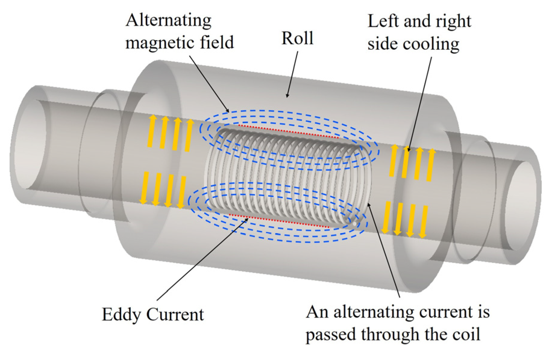
2.1. Basic Principle of Electromagnetic Control of Roll Profile

Electromagnetic control for roll profile is a technology based on the principle of electromagnetic induction, and the structure schematic diagram and the working principle are illustrated in Figure 1. The roll consists of a hollow sleeve and a central shaft, which are assembled via bearings. Induction coils are wound on the fixed central axis of the roll and connected to the external induction power supply. When the induction power supplies an alternating current to the induction coil, an alternating magnetic field is generated around it. Eddy currents are induced in the inner bore of the roll sleeve as it cuts the magnetic flux lines during rotation. As the generated eddy current flows against the resistivity of the roll, heat is generated by the principle of Joule heating.
Under the combined effect of central heating and edge cooling, a non-uniform temperature field develops within the roll, inducing differential thermal expansion. The elevated temperature at the roll center produces greater expansion compared to the cooler edges, thereby creating a specific roll crown profile. By precisely controlling induction heating parameters and edge cooling conditions, the desired roll crown configuration can be achieved.

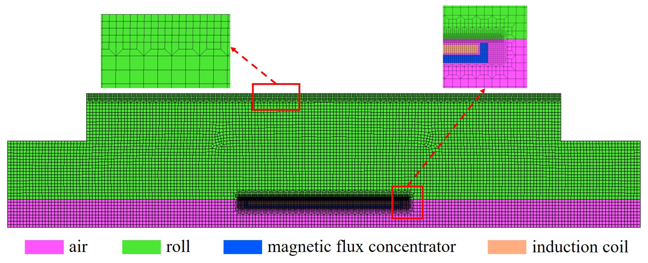
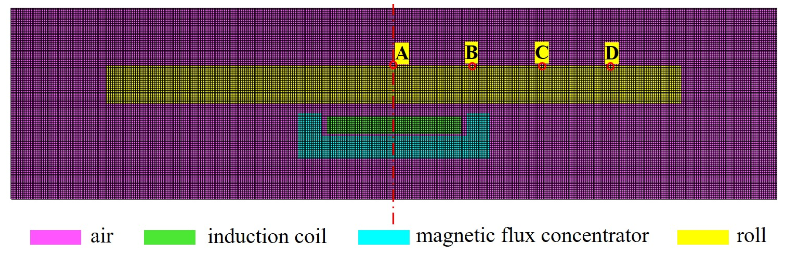
2.2. Finite Element Modeling

As the roll and the induction coil are geometrically axisymmetric, and the convective heat transfer boundary between the roll and cooling gas can be equivalently treated as an axisymmetric boundary [25], a simplified 2D axisymmetric electromagnetic–thermal–structural coupling finite element model is built in the soft-ware MARC, asshown in Figure 2. The roll dimensions are Φ850 × 1500 mm, and the specified internal control diameter is 180 mm. The heating section length is 500 mm. The model includes only the central through-hole air domain, neglecting the external air domain as it minimally affects the induction heating zones due to the roll’s large diameter.
The roll is made of 45# steel, and its mechanical properties are defined based on the parameters provided by the finite element software MARC. The thermomagnetic properties are determined using the data listed in Table 1.
Magnetic flux concentrators are critical for enhancing induction heating efficiency in roll bore applications. Positioned with their opening facing the roll and adjacent to the induction coil, the concentrator establishes a closed magnetic path to focus flux on the target zone, thus concentrating eddy currents near the surface for rapid internal heating and preventing parasitic heating in adjacent areas.
For medium-to-low induction heating, silicon steel laminations are typically chosen as the material for magnetic flux concentrators, attributed to their exceptional magnetic permeability, low core loss characteristics, saturation capability, and excellent thermal stability [26]. In the simulation, the resistivity of the silicon lamination is set to 4.5 × 10⁻⁵ Ω·m, and the B-H curve is shown in Figure 3. To maximize the magnetic flux concentrator’s performance, the silicon lamination should be maintained below the saturation induction point (Bs).
When applying current boundary conditions, the loading applied on the coil is represented as equivalent current density Js, which can be calculated by Equation (1):
J s = n I / S ,
where n is the number of turns of the coil; I is the current (A); and S is the effective cross-sectional area of the coil (mm2), modelled as a rectangle with S = , where L is the length of the coil cross-section and δ is skin depth (m) as calculated by Equation (2):
δ = 2 ρ ω μ = ρ π f μ ,
where ρ = 1.71 × 10⁻⁸ Ω·m is the resistivity of the copper coil, μ is the permeability (H/m), defined as μ = μrμ0, with μ0 = 4π × 10−7 H/m being the vacuum permeability, and μr = 1 the relative permeability.
The initial temperature of the roll is set to 20 °C. The roll surface and sides experience convective heat transfer with air modelled with a combined heat transfer coefficient of 10 W/(m2·K). The distal air unit is designated as both the magnetic potential zero point and the electric potential zero point.

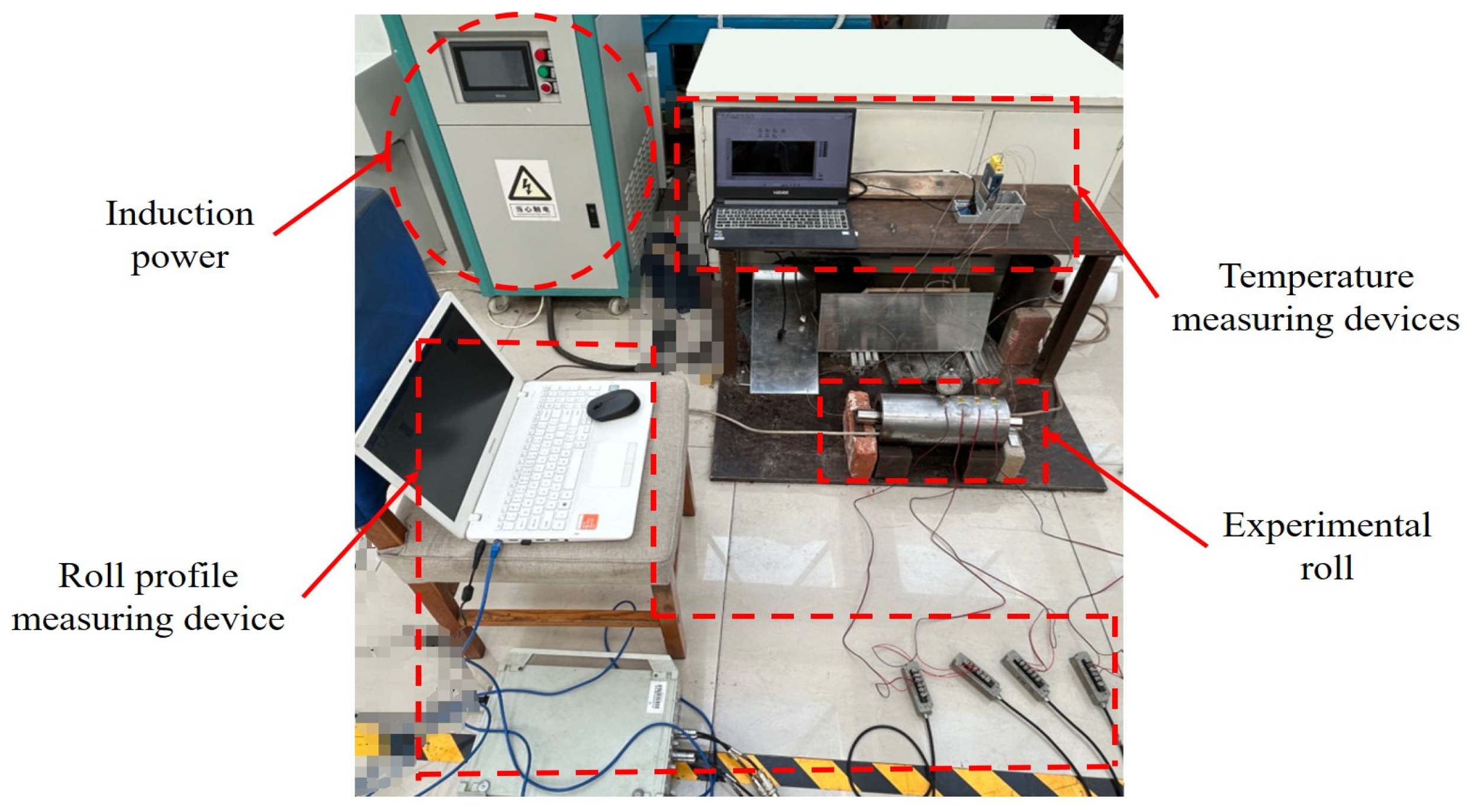
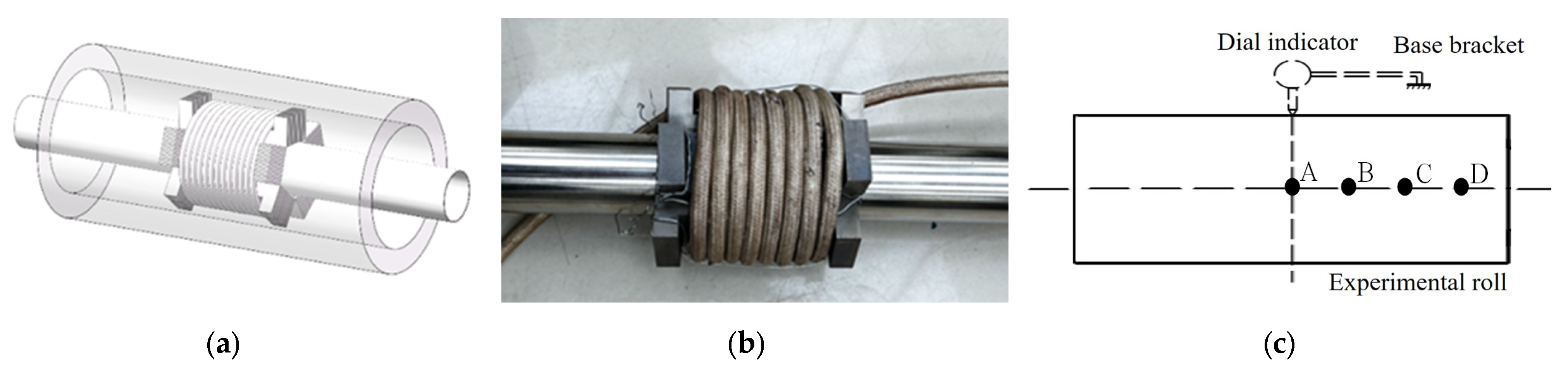
2.3. Validation Experiment

As shown in Figure 4, the experimental platform comprises four primary subsystems: the roll system, the variable-frequency power supply, the temperature measurement device, and the roll profile measurement device. The induction power supply operates at frequencies of 400–4000 Hz with a current capacity of 0–300 A and a maximum power output of 15 kW.
The roll system utilized a thick-walled 45# steel cylinder with 100 mm inner diameter, 140 mm outer diameter, and 300 mm length as the roll. The central shaft was made from non-magnetic 304 stainless steel to prevent temperature rise during induction heating. Five U-shaped silicon steel flux concentrators with 100 mm length were uniformly distributed around the shaft with their openings facing outward, securely fastened with steel wires. A copper induction coil with eight turns (n = 8) was precisely wound on flux concentrators, and the entire assembly was mounted inside the roll to facilitate effective inner wall heating, as shown in Figure 5a,b.
The roll surface temperature was measured using K-type surface-mounted thermocouples, which were connected to an NI temperature acquisition card for real-time monitoring via LabVIEW software-community edition. The roll profile was indirectly measured by real-time monitoring of circumferential strain using temperature-compensated strain gauges configured in a quarter-bridge circuit, which were connected to a dynamic testing and analysis system via a strain adapter. Four strain gauges were equally spaced from the roll’s midpoint to its edge, all aligned parallel to the cylindrical axis with matching circumferential orientation. Corresponding thermocouples were installed adjacent to each strain gauge at identical axial positions for synchronized temperature and strain measurements. A precision dial indicator was concurrently used to monitor the roll diameter variations for validation of the strain gauge measurements, and the schematic diagram is shown in Figure 5c. A, B, C, and D are the points corresponding to 0, 40, 80, and 120 mm away from the center of the roll.
Due to nonlinear variations in the thermal expansion coefficient and resistance-temperature characteristics of the strain gauges, residual error compensation remains necessary. The thermal output (residual error) curve of these strain gauges is presented in Figure 6. These gauges demonstrate a parabolic thermal output profile, achieving optimal compensation at 25 °C while showing increased deviations at higher or lower temperatures. The radial deformation at each point of the roll surface is calculated by Equation (3), and the relationship between the radial change of the roll at different axial positions and the heating time is obtained to obtain the roll profile at any moment.
Δ r = ε z r
where εz is the circumferential strain of the roll surface, Δr is the radius change of the measurement point (μm), and r is the radius of the measurement point (μm).

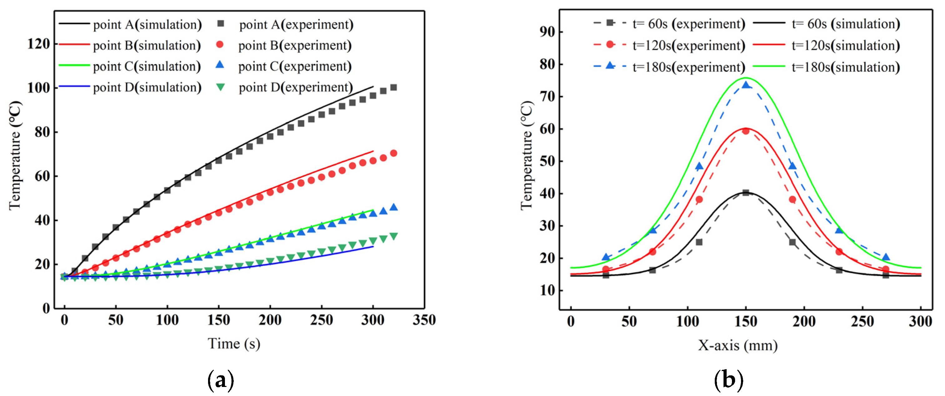
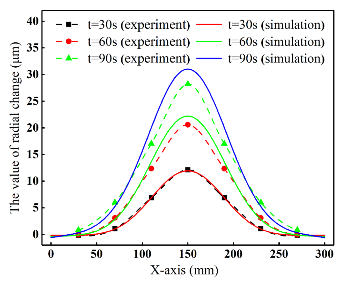
3. Validation of the Finite Element Model

An experimental study was carried out on the constructed experimental platform to verify the accuracy of the constructed simulation model. The current intensity was 30 A, the current frequency was 1000 Hz, and the ambient temperature was 14.5 °C. The FE model, consistent with experimental conditions, was established, as illustrated in Figure 7. The coil length is 70 mm, the diameter is 80 mm, and the wire diameter is 8 mm. Given the relatively small size of the roll, the air domain was explicitly included in this model to improve the accuracy of the electromagnetic field simulations. There are 40,000 elements in total. In order to balance the computational efficiency and the accuracy requirements of small deformation analysis, the element type is selected as a four-node quadrilateral. The current intensity was converted to equivalent current density using Equation (1) and incorporated into the model for numerical solution. The simulated roll surface temperature and deformation data were then extracted for comparison with experimental measurements.
Figure 8a presents the experimental temperature–time curves for points A-D on the roll surface. After 300 s of heating, the points reached temperatures of 96.5 °C, 67.0 °C, 42.8 °C, and 31.1 °C, respectively. Corresponding simulation results showed temperatures of 100.7 °C, 71.3 °C, 44.7 °C, and 28.1 °C at these four points. The close agreement between experimental and simulated temperatures validates the model, with point D showing slightly moderate precision.
The roll surface temperature distribution was further analyzed at t = 60 s, 120 s, and 180 s. As shown in Figure 8b, the maximum surface temperature reached 40.3 °C, 59.4 °C, and 73.4 °C, respectively, while the maximum temperature differences across the surface were 25.6 °C, 42.8 °C, and 53.2 °C. This progressive heating pattern demonstrates faster thermal response at the roll center compared to the edges. Although simulated temperatures were slightly higher than experimental values, both datasets exhibited identical trends, confirming the finite element model’s accuracy in predicting the thermal behavior.
The radial change of the midpoint of the roll surface obtained from the dial indicator, strain gauge, and simulation is compared in Figure 9. The results show consistent deformation trends across all three methods. The simulation, based on theoretical calculations, yields higher values than the strain gauge and dial indicator measurements. The difference between the latter two is minimal, with minor deviations likely due to operational or reading errors. Figure 10 compares the experimental and simulated roll profiles at different moments. The results show that the accuracy is relatively high for the first 30 s; however, an increase in error is observed as time progresses. The simulated roll profile was 31 μm after being heated for 90 s, while the experimental result was 28.2 μm. The discrepancy between the two was less than 10%, confirming the simulation model’s high accuracy and consistency with experimental data.

4. Results

4.1. Effects of Electromagnetic Control Parameters on Roll Profile

Based on the established simulation model, the influence of different electromagnetic process parameters on the roll temperature, roll profile, and roll crown was investigated. The electromagnetic parameters are presented in Table 2.
Roll profile curve and roll crown are used to describe the shape and characteristics of the roll, roll crown CW for the roll surface center position and the roll surface edge position of the radial change of the amount of difference, the calculation formula is:
CW = CMCS,
where CM is the radial deformation (μm) at the center point of the roll surface; CS is the radial deformation (μm) at the edge point of the roll surface.

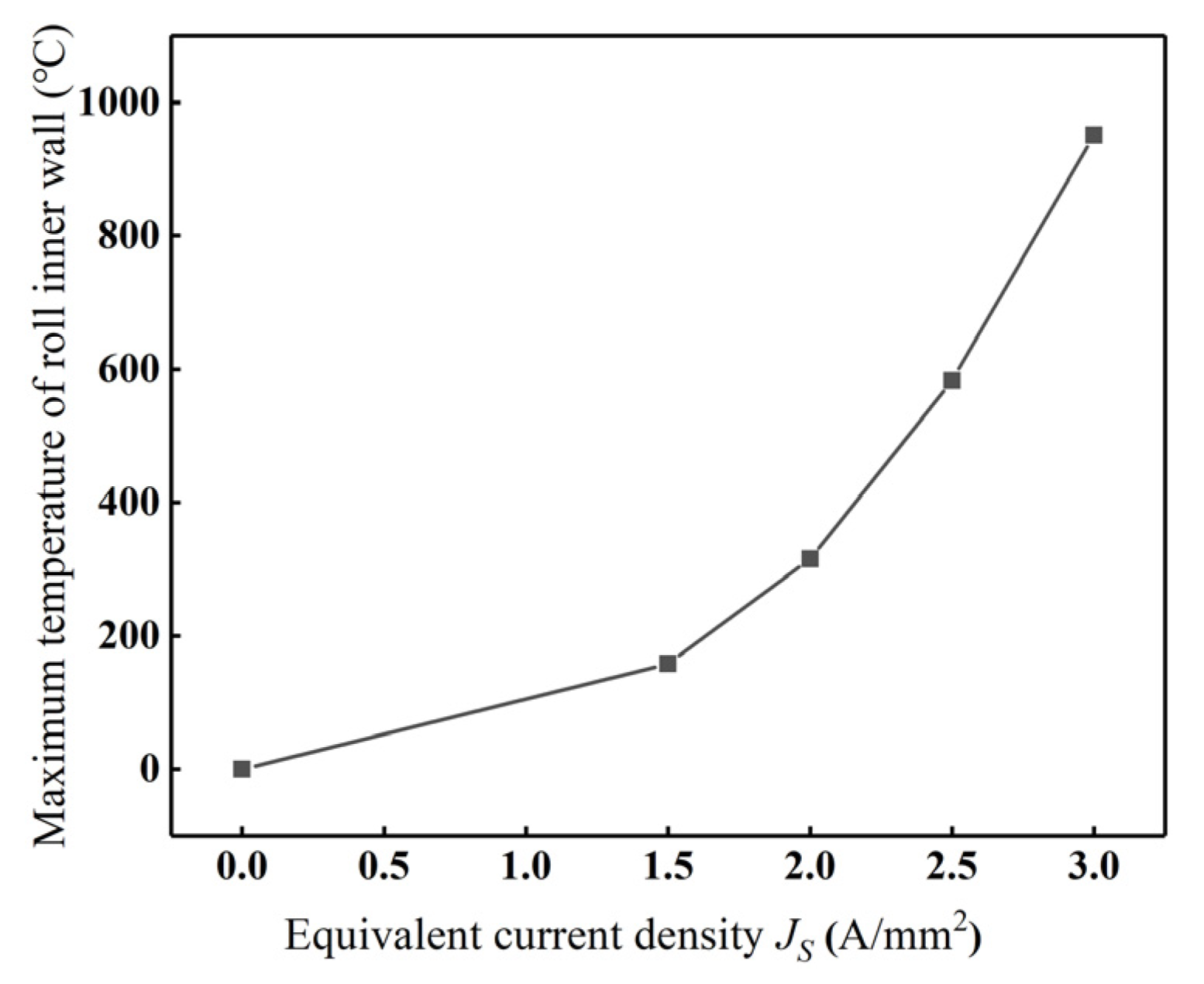
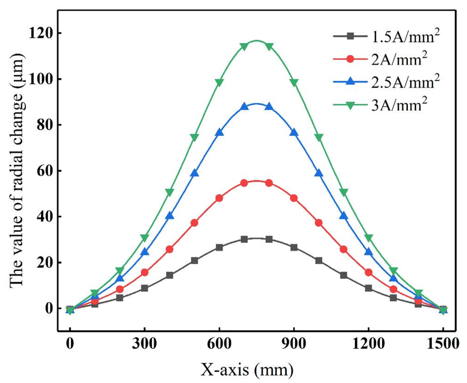
4.1.1. Equivalent Current Density

The equivalent current density is a critical parameter in electromagnetic induction heating, as it directly determines the heating temperature and rate. Insufficient current density may fail to achieve the desired heating effect and unnecessarily prolong the processing time. Conversely, an excessively high current density can lead to overheating of the roll, thereby compromising the heating quality. Therefore, selecting an appropriate current density is essential for achieving optimal heating efficiency.
Under the conditions of current frequency f = 1000 Hz and coil turn n = 50, four equivalent current densities Js = 1.5, 2, 2.5, and 3 A/mm2 were investigated. The roll deformation caused by thermal expansion was analyzed under a constant heating duration of 300 s. The simulation results are shown in Figure 11. It demonstrates that the maximum temperature of the roll’s inner wall increases nonlinearly with the rise in Js, and the rate of temperature increase also increases with Js. The maximum inner wall temperatures corresponding to Js = 1.5, 2, 2.5, and 3 A/mm2 reached 158.2 °C, 315.1 °C, 582.7 °C, and 950.8 °C, respectively. It implies that higher Js values produce both greater temperature magnitudes and faster heating rates.
Figure 12 shows the roll profile curves under different equivalent current densities at t = 300 s. Due to internal induction heating applied to the central region of the roll, the deformation speed at the midpoint of the roll surface is the highest, while the edge of the roll surface remains unchanged during the heating. An increase in Js leads to a corresponding increase in the roll crown.

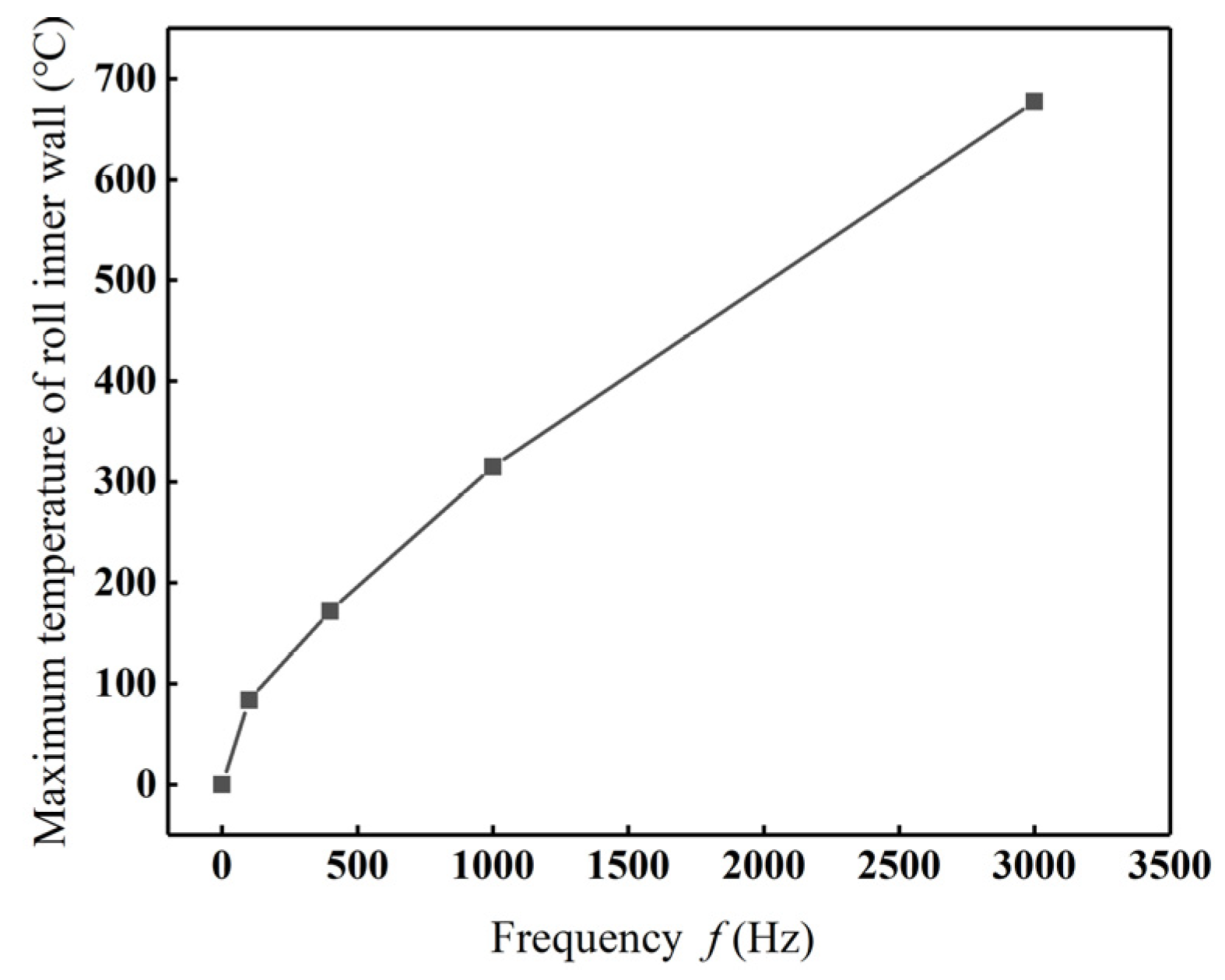
4.1.2. Current Frequency

The current frequency controls the skin depth of induction heating. High frequency induces a small skin depth, which means the high-frequency current is mainly distributed on the surface of the conductor, and the heating is mainly concentrated in the surface layer of the roll’s inner bore. Low-frequency current has a large penetration depth, but the heating speed is slow. Therefore, it is also very important to choose the appropriate current frequency in the induction heating process.
Under the equivalent current density Js = 2 A/mm2, coil turn n = 50, and the heat time t = 300 s, the maximum temperature of the roll inner bore and the roll profile corresponding to f = 100, 400, 1000, and 3000 Hz are shown in Figure 13 and Figure 14. It can be seen that the temperature rises with the increasing frequency. The maximum temperature of the roll inner bore reaches 83.8 °C, 172 °C, 315 °C, 677 °C, and the radial changes of the midpoint of the roll surface are 13.2 μm, 32.5 μm, 55.5 μm, and 92.6 μm, respectively. Increased frequency leads to greater convexity in the roll profile curves for the same heating time.
Coil turn n determines the strength of the magnetic field and the heating efficiency, but it also increases the coil resistance, which will result in substantial voltage reduction and energy dissipation.
When the equivalent current density Js is set to 2 A/mm2, the frequency f = 1000 Hz, and the heat time t = 300 s, the maximum temperature of roll inner bore and the roll profile corresponding to the coil turn n = 20, 30, 40, and 50 are shown in Figure 15 and Figure 16. Figure 15 shows that the maximum temperature of the roll inner bore rises with the increasing coil turns due to intensified magnetic field intensity and improved heating efficiency. However, the maximum temperature change rate declines with the growth of the coil turns. The reason is that when Js and f remain constant, increasing the coil turn simultaneously raises the coil impedance, leading to greater voltage drop and energy consumption. This combined effect results in a slower maximum temperature rise rate of the roll. The roll crown increases with the number of coil turns, showing values of 19.5 μm, 32.0 μm, 44.7 μm, and 55.5 μm, respectively, as illustrated in Figure 16.

4.2. Analysis of Roll Profile Control Strategy

In the process of electromagnetic roll profile control, continuous induction heating of the roll inner bore leads to a progressive temperature rise and enlarges the roll heat deformation until it eventually reaches a thermal equilibrium state. However, since roll profile adjustment requires achieving the target profile within a short timeframe, persistent heating under the selected induction parameters would result in an equilibrium roll crown significantly exceeding the desired value. During electrode calendering, the required roll crown is relatively small, typically on the order of tens of micrometers. Therefore, this study adopts a periodic heating strategy to achieve and maintain the desired thermal profile [27].

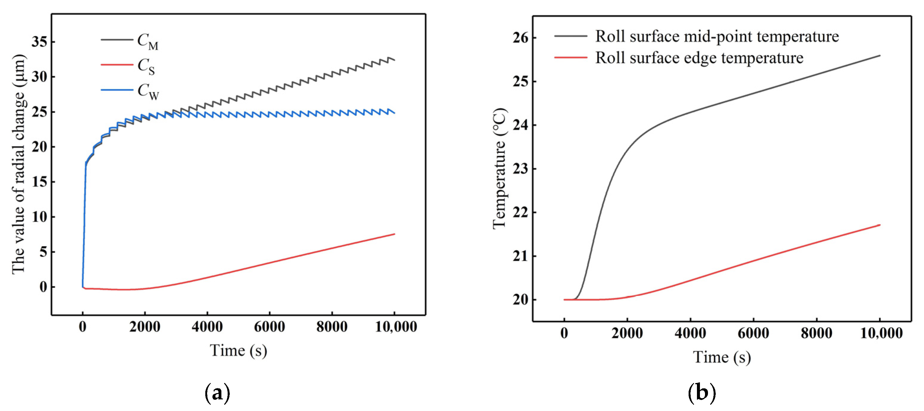
4.2.1. Effectiveness of the Segmented Periodic Heating Strategy

The process involves two stages: first, continuous heating is applied to achieve the target roll profile, followed by periodic heating to maintain profile stability. In this process, the cycle heating time parameter, electromagnetic process parameter, and cooling conditions jointly govern the final profile and its stability. The main time parameters involved are the total regulation time t, the first heating time t1, the cycle heating time T1, the cycle stopping time T2, and the duty cycle T1/T2.
When Js = 2 A/mm2, f = 1000 Hz, coil turn = 50, duty cycle = 1/50, t1 = 100 s, T1 = 5 s, if the cooling intensity is 0. At this time, the changes in CM, CS, CW, and roll surface temperature with the heating time are shown in Figure 17. As shown in Figure 17a, the radial deformation at the roll surface center and the edge, CM and CS are increasing with the cycle heating, and both of them have the same rate of growth, such that the roll crown CW maintains stability. However, the roll profile varies continuously, which leads to ongoing changes in the roll gap; hence, it cannot be adopted in actual production. Figure 17b shows that the roll surface temperature exhibits a rising trend with heating cycles, similar to the deformation.
To satisfy both roll profile control requirements for electrode calendering and production cleanliness standards, an internal gas cooling was selected for segmented roll cooling, as shown in Figure 18. The roll inner bore is divided into three cooling segments: the left side of the cooling zone, the right side of the cooling zone, and the central cooling zone. Through iterative simulation and adjustments, 20 °C gas cooling with a convective heat transfer coefficient of 200 W/(m2·K) was applied to the inner hole of the roll, while 15 °C gas cooling with a convective heat transfer coefficient of 300 W/(m2·K) was applied to both sides of the inner hole, resulting a stable roll profile at duty 1/50. As shown in Figure 19, the roll profile stabilizes at approximately 3000 s and maintains stability through subsequent periodic heating. Figure 20 demonstrates the roll profile curve, and the roll surface temperature remains stable at 4000 s, 6000 s, 8000 s, and 10,000 s, confirming that periodic heating is an effective method for roll profile stabilization.

4.2.2. Effects of Critical Control Parameters Js and t1

The target roll crown is mainly controlled through the equivalent current density Js and the first heating time t1, and then the duty cycle and cooling conditions can be adjusted at different Js and t1 to maintain the roll profile stable. It is essential to establish a mathematical relationship between Js, t1, and the stabilized roll crown CW for the practical application of electromagnetic roll profile control technology.
Keeping the equivalent current density Js fixed at 2.0 A/mm2, t1 was set to 100 s, 200 s, 300 s, and 400 s, respectively, and the stable roll crowns under different t1 were obtained by adjusting the duty cycle and cooling conditions. The stabilized roll crowns are shown in Figure 21a. The stabilized roll crowns corresponding to different t1 are 19.6 μm, 42.2 μm, 58.1 μm, and 78.1 μm, respectively, showing a linear relationship with t1. The first heating time t1 = 200 s, and Js were set to 1.5, 2, 2.5, and 3 A/mm2, the stabilized roll crowns shown in Figure 21b were 23.2 μm, 42.2 μm, 69.6 μm, and 107.4 μm, demonstrating a nonlinear relationship with Js.
Based on the linear relationship between t1 and the stabilized roll crown, adjusting t1 is prioritized in practical applications to achieve the target crown. However, in actual production, the roll temperature imposes process constraints, coordinated control of both current density Js and heating time t1 according to the control requirements.

5. Discussion and Conclusions

To address the roll profile control requirements for achieving transverse thickness uniformity in wide-format electrode calendering processes, this work proposes a flexible regulation technology for rolls based on electromagnetic induction heating. By establishing a validated axisymmetric electromagnetic–thermal–structural coupling finite element model and conducting systematic simulations to investigate the regulation behavior, the roll profile control strategy of cyclic heating is proposed, and the following conclusions are drawn:
(1)
An axisymmetric electromagnetic–thermal–structural coupling finite element model was developed and experimental validation was performed using a self-built experimental platform, with measured temperature and deformation field data showing excellent agreement with FEM predictions.
(2)
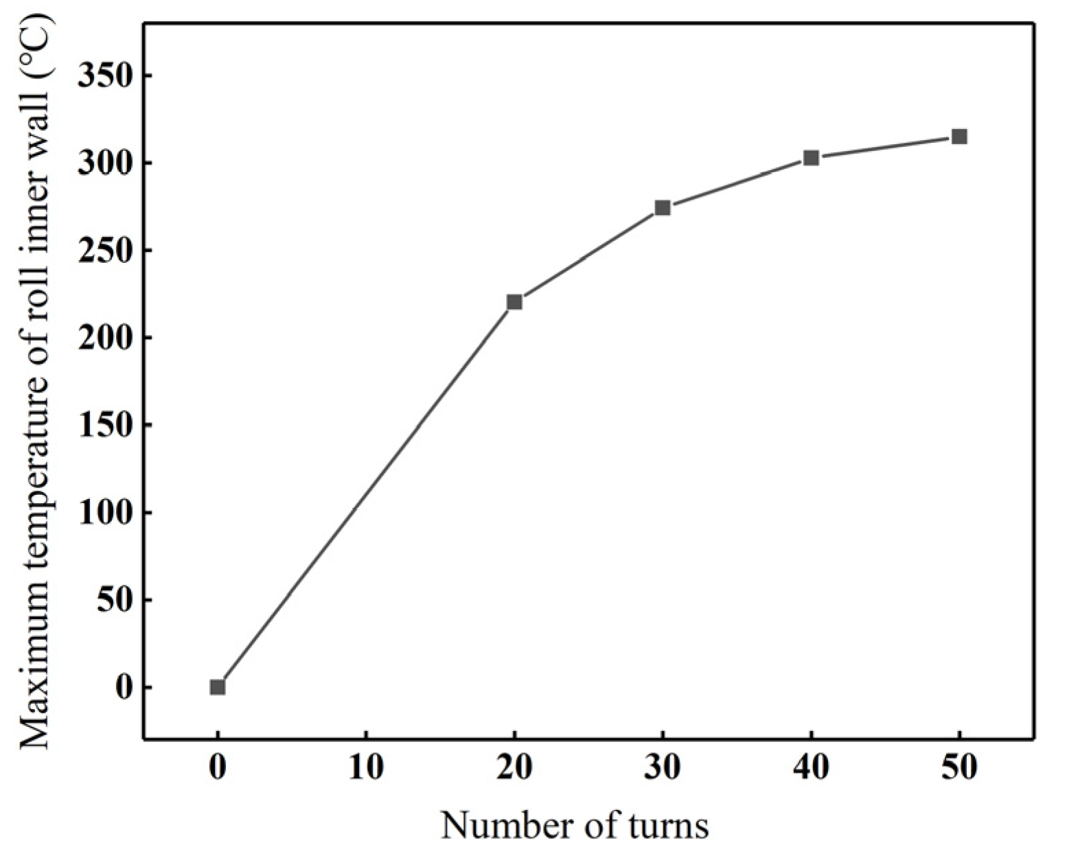
The influence of key electromagnetic process parameters, including equivalent current density (Js), current frequency f, and coil turn n, on the roll temperature, roll profile, and roll crown was investigated. The maximum temperature of the roll’s inner bore and the roll crown exhibit an increasing trend as Js, f, and n increase. Moreover, the maximum temperature of the roll’s inner bore exhibits a quadratic relationship with Js. As Js continues to increase, the rate of temperature rise accelerates. However, the rate of temperature rise decreases with the increase in f and n.
(3)
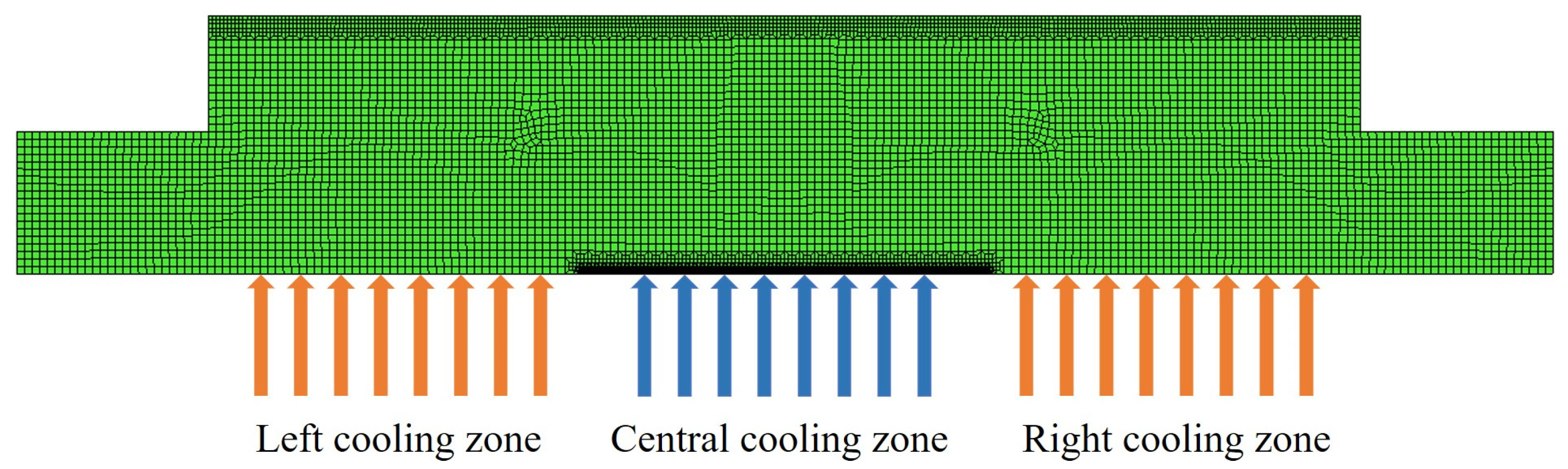
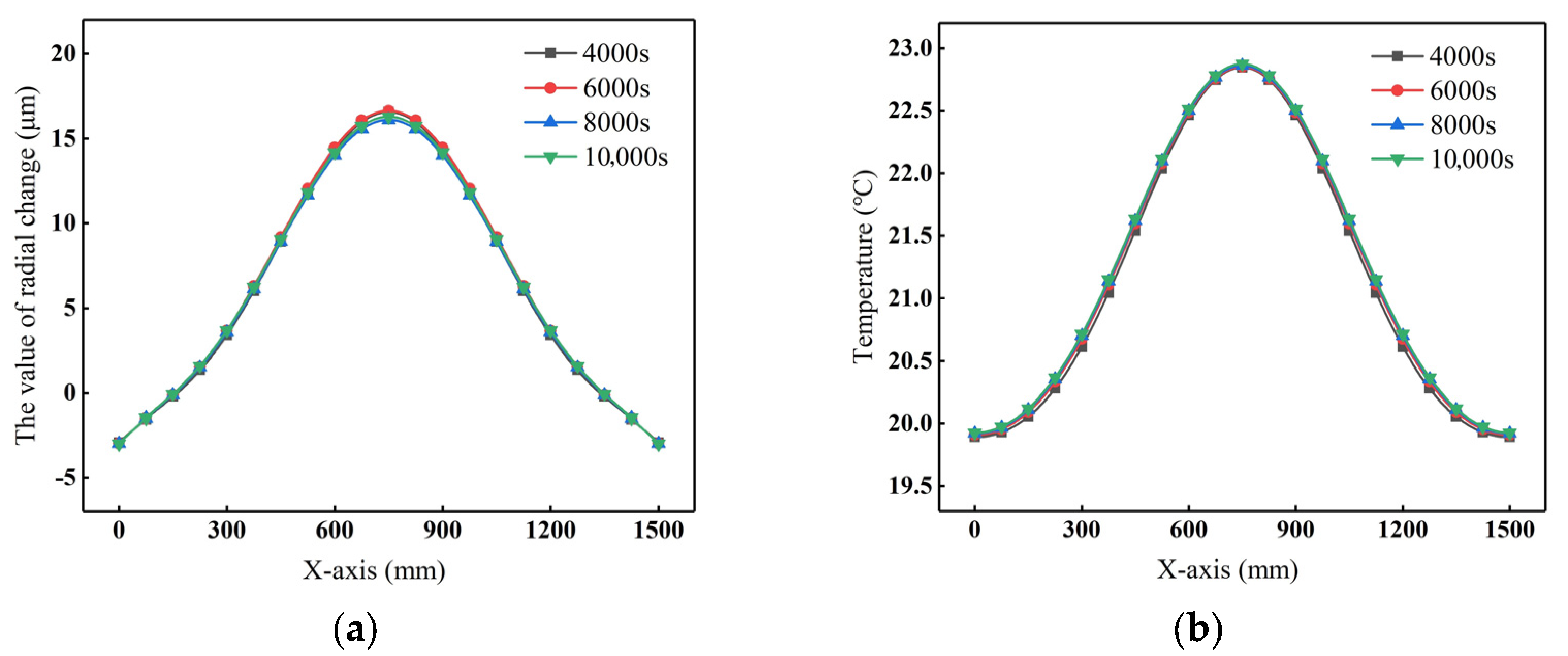
A cyclic heating strategy was developed to control and stabilize the roll profile. The simulation results show that the roll profile can be effectively regulated by adjusting current density Js and heating durations t1. The stable crown CW shows linear correlation with t1, and a nonlinear trend with Js. Under fixed Js and t1, further optimization of duty cycle and cooling conditions enables long-term stabilization of the roll profile.
In conclusion, the proposed electromagnetic induction heating method enables effective and flexible roll profile control through coordinated regulation of inner-wall heating and cooling conditions, demonstrating significant potential for the wide-format electrode calendering process. However, further studies are still required, including validating the method on industrial-scale calendering mills, refining the integrated control system and auxiliary systems, and developing real-time readjustment strategies for online profile adaptation during production.

Author Contributions

Conceptualization, H.H. and J.S.; methodology, J.S.; software, H.C.; validation, C.G. and H.C.; formal analysis, C.G. and H.C.; investigation, X.F.; resources, Z.Y.; data curation, H.C.; writing—original draft preparation, C.G. and H.C.; writing—review and editing, J.S.; visualization, H.H.; supervision, Z.Y.; project administration, J.S.; funding acquisition, J.S. All authors have read and agreed to the published version of the manuscript.

Funding

This research was funded by the S&T Major Program of Hebei, grant No. 23281901Z; Key S&T Special Projects of Xingtai City, grant No. 2023ZZ017.

Data Availability Statement

The data used to support the findings of this study are available from the corresponding author upon request.

Acknowledgments

Authors would like to acknowledge the support from Xingtai Naknor Technology Co., Ltd.

Conflicts of Interest

Author Hao Chen was employed by the company CISDI Thermal & Enviromental Engineering Co., Ltd. Author Zhijie Yang was employed by the company Xingtai Naknor Technology Co., Ltd. The remaining authors declare that the research was conducted in the absence of any commercial or financial relationships that could be construed as a potential conflict of interest.

References

  1. Zhu, G.D.; Sun, X.; Ai, C.S. Research on the on-line monitoring and control system of lithium battery pole piece surface density. Adv. Mater. Res. 2014, 889, 691–694. [Google Scholar] [CrossRef]
  2. Zheng, H.; Li, J.; Song, X.Y.; Liu, G.; Battaglia, V. A comprehensive understanding of electrode thickness effects on the electro-chemical performances of Li-ion battery cathodes. Nat. Energy 2012, 71, 258–265. [Google Scholar]
  3. Wang, D.C.; Wang, G.D.; Xu, C.J.; Liu, H.M. Mechanics and deformation behavior of lithium-ion battery electrode during calendering process. J. Energy Storage 2024, 87, 111521. [Google Scholar] [CrossRef]
  4. Haidar, A.; Kubra, U.; Yang, T.C. Low porosity NMC622 and NMC811 electrodes made by severe calendering. J. Energy Storage 2025, 105, 114559. [Google Scholar]
  5. Zu, C.X.; Li, H. Thermodynamic Analysis on Energy Densities of Batteries. Energy Environ. Sci. 2011, 4, 2614–2624. [Google Scholar] [CrossRef]
  6. Elzbieta, S.; Leszek, S. Comparative analysis of effectiveness of resistance and induction turnout heating. Energies 2020, 13, 5262. [Google Scholar] [CrossRef]
  7. Long, J.J.; Yu, H.; Liu, W.B. Structure engineering of cathode host materials for Li-S batteries. Rare Met. 2024, 43, 1370–1389. [Google Scholar] [CrossRef]
  8. Li, H.; Chen, Z.D.; Kang, Z.R.; Liu, W.; Chen, Y.G. High-density crack-resistant Si-C microparticles for lithium ion batteries. Energy Storage Mater. 2023, 56, 40–49. [Google Scholar] [CrossRef]
  9. Zhang, L.Y.; Gong, H. Partial conversion of current collectors into nickel copper oxide electrode materials for high-performance energy storage devices. ACS Appl. Mater. Amp Interfaces 2015, 7, 15277–15284. [Google Scholar] [CrossRef]
  10. Sun, J.N.; Xiang, W.J.; Huang, H.G.; Yuan, Z.G.; Li, J.R. Research progress on rolling technology of lithium-ion battery electrodes. China Metall. 2021, 31, 12–18. [Google Scholar]
  11. Zhang, J.P.; Sun, J.N.; Huang, H.G.; Ji, C.; Yan, M.; Yuan, Z.G. Deformation and fracture mechanisms in the calendering process of lithium-ion battery electrodes. Appl. Energy 2024, 373, 123900. [Google Scholar] [CrossRef]
  12. Duffner, F.; Kronemeyer, N.; Tübke, J.; Leker, J.; Winter, M.; Schmuch, R. Post-lithium-ion battery cell production and its compatibility with lithium-ion cell production infrastructure. Nat. Energy 2021, 6, 123–134. [Google Scholar] [CrossRef]
  13. Gavalas, E.; Papaefthymiou, S. Thermal Camber and Temperature Evolution on Work Roll during Aluminum Hot Rolling. Metals 2020, 10, 1434. [Google Scholar] [CrossRef]
  14. Gao, Y.J.; Zhao, J.Y.; Kong, X.D.; Wang, Y.Q. Dynamic simulation of a hydraulic AGC system for a strip mill. China Mech. Eng. 1998, 7, 23–26. [Google Scholar]
  15. Jia, C.Y.; Shan, X.Y.; Cui, Y.C.; Bai, T.; Cui, F.J. Modeling and simulation of hydraulic roll bending system based on CMAC neural network and PID coupling control strategy. J. Iron Steel Res. Int 2013, 20, 17–22. [Google Scholar] [CrossRef]
  16. Ding, J.G.; He, Y.H.C.; Song, M.X.; Jiao, Z.J.; Peng, W. Roll crown control capacity of sextic CVC work roll curves in plate rolling process. Int. J. Adv. Manuf. Technol. 2021, 113, 87–97. [Google Scholar] [CrossRef]
  17. Bai, Z.H.; Wang, K.; Wang, Y.J.; Chang, J.L.; Zhou, Q.T.; Ke, Y.L. Inner roll shape optimization design technology of VC mill. China Mech. Eng. 2013, 24, 3096–3100. [Google Scholar]
  18. Wang, Q.N.; Sun, J.Q.; Yang, J.X.; Wang, H.S.; Dong, L.J.; Jiao, Y.L.; Li, J.M.; Zhi, Z.Y.; Yang, L.P. Online Partition-Cooling System of Hot-Rolled Electrical Steel for Thermal Roll Profile and Its Industrial Application. Processes 2024, 12, 410. [Google Scholar] [CrossRef]
  19. Yang, T.S.; Hai, Y.; Fan, M.C.; Xu, Z.Q.; Du, F.S. Research on electronic temperature control capability of roll profile based on semiconductor thermoelectric effect. J. Plast. Eng. 2022, 29, 206–213. [Google Scholar]
  20. Du, F.S.; Liu, W.W.; Feng, Y.S.; Sun, J.N. Roll profile electromagnetic control process parameters in precision rolling mill. Chin. J. Eng. 2017, 39, 1874–1880. [Google Scholar]
  21. Yang, T.S.; Sun, W.Q.; Xu, Z.Q.; Du, F.S.; He, A.R. Analysis of the energy efficiency and control ability under different magnetic flux forms in RPECT. Int. J. Heat Mass Transf. 2023, 217, 124730. [Google Scholar] [CrossRef]
  22. Liu, W.W.; Feng, Y.F.; Yang, T.S.; Du, F.S.; Sun, J.N. Theoretical and experimental research on the law of flexible roll profile electromagnetic control. J. Mater. Process. Tech 2018, 262, 308–318. [Google Scholar] [CrossRef]
  23. Feng, Y.F.; Liu, W.W.; Yang, T.S.; Du, F.S.; Sun, J.N. A flexible electromagnetic control technique for interference adjustment in large-size sleeved backup rolls. Metall. Res. Technol 2019, 116, 405. [Google Scholar] [CrossRef]
  24. Liu, W.W.; Li, T.; Wang, T.; Fu, X.B.; Du, F.S. Analysis of the influence of roll size change on electromagnetic heat conversion capacity and roll profile control characteristics in the RPECT. Int. J. Heat Mass Transf. 2022, 189, 122686. [Google Scholar] [CrossRef]
  25. Li, W.G.; Liu, X.H.; Guo, Z.H. Numerical simulation of temperature field and thermal crown of work roll during hot strip rolling. Chin. J. Nonferrous Met. 2012, 11, 3176–3184. [Google Scholar]
  26. Zhiye, L.; Yuechao, M.; Anrui, H. Investigation and Application of Magnetic Properties of Ultra-Thin Grain-Oriented Silicon Steel Sheets under Multi-Physical Field Coupling. Materials 2022, 15, 8522. [Google Scholar] [CrossRef]
  27. Zhu, Y.; Yu, S.W.; Liang, R.; Luo, Y. Numerical simulation of induction heating process based on magnetic-thermal coupling. Hot Work. Technol. 2020, 49, 89–92. [Google Scholar]
Figure 1. Basic principle diagram of electromagnetic roll profile control.
Processes 13 01448 g001
Figure 2. Electromagnetic–thermal–structural coupling axisymmetric model.
Processes 13 01448 g002
Figure 3. B-H curve of silicon lamination.
Processes 13 01448 g003
Figure 4. Experimental platform.
Processes 13 01448 g004
Figure 5. Schematic and physical diagram of the experimental device: (a) Schematic diagram; (b) Physical diagram. (c) Schematic diagram of the dial indicator position.
Processes 13 01448 g005
Figure 6. Temperature self-compensating strain gauge thermal output versus temperature (residual error).
Processes 13 01448 g006
Figure 7. Axisymmetric model for roll profile electromagnetic control experiments.
Processes 13 01448 g007
Figure 8. Comparison of experimental and simulated temperatures: (a) Curves of temperature at each point of the roll surface with time, (b) Temperature distribution curves of the roll surface at different times.
Processes 13 01448 g008
Figure 9. Radial variation of roll surface midpoint with time for different measurement methods.
Processes 13 01448 g009
Figure 10. Comparison of experimental and simulated roll profiles at different moments.
Processes 13 01448 g010
Figure 11. Maximum temperature of the roll inner wall at different Js (t = 300 s).
Processes 13 01448 g011
Figure 12. Roll profile curves at different equivalent current densities (t = 300 s).
Processes 13 01448 g012
Figure 13. Maximum temperature of the inner wall of the roll at different frequencies (t = 300 s).
Processes 13 01448 g013
Figure 14. Roll profile curves at different frequencies (t = 300 s).
Processes 13 01448 g014
Figure 15. Maximum temperature of the inner wall of the roll at different numbers of turns (t = 300 s).
Processes 13 01448 g015
Figure 16. Roll profile curves at different turns (t = 300 s).
Processes 13 01448 g016
Figure 17. Roll surface deformation and temperature conditions before applying cooling: (a) Deformation, (b) Temperature.
Processes 13 01448 g017
Figure 18. Schematic diagram of internal segmented cooling.
Processes 13 01448 g018
Figure 19. Roll surface deformation and temperature after applying cooling control: (a) Deformation, (b) Temperature.
Processes 13 01448 g019
Figure 20. Roll profile curve and roll surface temperature distribution at different times after cooling control is applied: (a) Roll profile curve, (b) Roll surface temperature distribution.
Processes 13 01448 g020
Figure 21. Relationship curve: (a) t1 and CW, (b) Js and CW.
Processes 13 01448 g021
Table 1. Main material parameters for 45# steel.
Temperature (°C)Thermal Conductivity (W/(m·K))Relative PermeabilitySpecific Heat Capacity (J/(kg·K))Resistivity
(10−6 Ω·m)
2047.682004720.198
10043.531954800.254
20040.44186.64980.339
40036.02167.15600.541
50034.16154.96150.656
60031.98137.87000.790
70028.6692.58540.949
74226.2019861.019
76025.14110641.042
90025.9216371.162
100024.0216021.20
Table 2. Electromagnetic parameters.
Electromagnetic Parameters Variation Range
Current density (A/mm2)1.5, 2, 2.5, 3
frequency (Hz)100, 400, 1000, 3000
Number of turns 20, 30, 40, 50
Disclaimer/Publisher’s Note: The statements, opinions and data contained in all publications are solely those of the individual author(s) and contributor(s) and not of MDPI and/or the editor(s). MDPI and/or the editor(s) disclaim responsibility for any injury to people or property resulting from any ideas, methods, instructions or products referred to in the content.

