Article

Electrolyte Optimization for Anthraquinone-Based Slurry Batteries

1
Faculty of Metallurgical and Energy Engineering, Kunming University of Science and Technology, Kunming 650093, China
2
Yunnan Provincial Key Laboratory of Intensification Metallurgy, Kunming University of Science and Technology, Kunming 650093, China
*
Author to whom correspondence should be addressed.
Processes 2025, 13(5), 1403; https://doi.org/10.3390/pr13051403
Submission received: 4 April 2025 / Revised: 27 April 2025 / Accepted: 1 May 2025 / Published: 4 May 2025
(This article belongs to the Special Issue Energy Storage and Conversion: Next-Generation Battery Technology)

Abstract

:
AQ suspensions show strong potential as organic anodes for Li-ion slurry batteries. However, the influence of slurry electrolyte composition on the electrochemical behavior of AQ lacks systematic investigation. We explored the effects of different lithium salts and solvents in the electrolyte on the redox behavior of the AQ material electrode. An electrolyte (1 M LiTFSI dissolved in DME: DOL with a volume ratio of 1:1) optimized for AQ lithium slurry batteries exhibits a stable 2.3 V charge/discharge platform delivering a discharge specific capacity of 246.2 mAh g−1 at 1.25 A g−1 (approaching the theoretical value) with stable slurry reactor operation for over 47 h. This work establishes a structure-property relationship between electrolyte formulation and AQ electrode performance, offering a design principle for electrolyte selection in organic slurry-based battery systems.

1. Introduction

The imminent depletion of fossil fuel reserves has accelerated the global energy paradigm shift toward renewable sources and large-scale energy storage solutions [1,2]. Among emerging technologies, redox flow batteries (RFBs) present a promising approach for scalable long-duration energy storage, though their widespread implementation is constrained by inherent limitations in energy density [3]. In contrast, lithium-ion batteries (LIBs) have dominated energy storage research due to their superior energy density characteristics [4,5,6,7]. Semi-solid lithium slurry batteries (SLBs) represent an innovative hybrid technology that combines the high energy density of conventional LIBs with the unique energy–power decoupling feature inherent to RFB architectures [8]. Current SLB research still mainly employs conventional LIB inorganic electrode materials, despite their economic challenges due to scarce constituent elements [9,10,11]. Organic electrode materials (OEMs) offer a compelling alternative to traditional inorganic compounds, being primarily composed of earth-abundant elements (C, H, O, N, etc.) [12]. These materials present numerous advantages, including renewability, cost-effectiveness [13], and exceptional theoretical capacity [14], positioning them as a focal point for next-generation energy storage research [15]. Chen et al. reported a species of organic-based semisolid Li-RFBs using 10-methylphenothiazine (MPT), delivering a high volumetric capacity (55 Ah L–1) [16]. Zhao et al. reported a flow battery using a polyaniline (PANI) suspension electrode, demonstrating an energy density of 66.5 Wh L−1 with Zn as the counter electrode [17]. Gautam et al. developed an all-nonaqueous organic slurry battery using molecularly designed highly insoluble tetrathiafulvalene (TTF) based redox-active organic cathodes, with the system demonstrating an energy density of ~94 Wh L−1 [18].
Anthraquinone (AQ) has two pairs of carbonyl groups and exhibits a 2.3 V voltage platform relative to Li/Li+, which is a promising choice for LIBs anode materials [19]. In order to solve the problem of AQ dissolution, the researchers tried to synthesize the frame material with AQ monomer [20,21] and AQ/CMK-3 composite material, which inhibited the capacity attenuation caused by AQ dissolution to a certain extent, delivering an initial specific capacity of 205 mAh g−1 [22]. On the other hand, attempts have also been made to dissolve AQ in electrolytes for redox flow batteries and to improve their solubility by substituting functional groups for synthetic derivatives [23].
Semi-solid suspended liquid electrode is another feasible direction to solve the problem of AQ electrode dissolution [24]. Under normal circumstances, the largest proportion of the slurry is the organic electrolyte [25], and electrolytes are one of the key factors affecting the electrochemical performance of OEMs [26]. The cationic charge density in the electrolyte has a direct effect on the redox behavior of OEMs [27]. The polarity of the solvent [28] and the hydrogen bonding between the solvent and potential hydrogen bond acceptor groups of OEMs (C=O and C=N) can reduce the solubility of OEMs in the electrolyte [29]. On the other hand, the solvation effect of different solvents has an important influence on the basic electrochemical process of OEMs [30]. The high concentration of electrolytes also contributes to the stable circulation of OEMs [31].
In this work, the influence of different electrolyte components on the redox behavior of the AQ electrode was analyzed in depth; a suitable electrolyte solvent was selected for the AQ SLB. The SLB shows a discharge specific capacity of 246.2 mAh g−1 at 0.5 C, and the slurry reactor demonstrates an initial volumetric capacity of 42.2 Ah L−1 and maintains stable operation for 47 h. The abbreviations used throughout the text are listed in Table 1.

2. Materials and Methods

Electrolyte preparation: In an Ar-filled glove box, electrolytes were prepared as follows: 1 M LiFSI in ED: 1 M lithium bisfluorosulfonimide (LiFSI) dissolved in ethylene carbonate/dimethyl carbonate (EC/DMC; 3:7 by mass termed ED); 1 M LiTFSI in ED: 1 M lithium bis(trifluoromethanesulphonyl)imide (LiTFSI) dissolved in ED; 1 M LiTFSI in DD: 1 M LiTFSI dissolved in glycol dimethyl ether/1,3-dioxolane (DME/DOL; 1:1 by volume termed DD). All mixtures were stirred at 25 °C for 24 h under an Ar atmosphere, and the solvent was dehydrated using molecular sieves.
Material properties: Infrared spectroscopy was used to measure the infrared absorption spectra of AQ electrodes in the range of 400–4000 cm−1 in solvents and different electrolytes and in charge and discharge states. The AQ paste electrodes before and after the cycle were measured by an X-ray diffractometer in the scanning angle range of 5–90°. The morphology of AQ slurry samples was observed by scanning electron microscope (SEM). The separator permeability test of AQ dissolved in ED was evaluated using an H-type diffusion cell.
Electrochemical tests: The AQ electrode is made by mixing 80 wt.% AQ, 10 wt.% conductive agent Ketjenblack (KB), and 10 wt.% polyvinylidene fluoride (PVDF) binder in N-methylpyrrolidone (NMP). The mixed paste was spread on the carbon-coated Al foil with a thickness of 150 μm, dried in the oven for 12 h under vacuum, and cut into 14 mm diameter round sheets. The AQ slurry electrode was mixed with 8 wt.% AQ, 1 wt.% KB, 1 wt.% Triton X-100 (TX-100), and 90 wt.% configuration electrolytes in an Ar atmosphere glove box, and evenly coated on a circular carbon cloth (CC) with a diameter of 14 mm. Lithium metal was used as the counter electrode. The CR2025 button battery was assembled in an Ar-filled glove box using the Celgard 2325 diaphragm. The slurry static reactor was assembled using a 3 × 3 cm S-shaped flow channel filled with AQ slurry with 1 M LiTFSI in DD electrolyte as the solvent, covered with a diaphragm wet with electrolyte, and sealed by a diaphragm on both sides of the reactor with a metal lithium strip as the opposite electrode. The prepared batteries were subjected to a CV test using an electrochemical workstation (Shanghai Chenhua) with a sweep speed of 1 mv s−1, and the cyclic performance was tested on the LAND test system. The slurry AQ half-cell was initially activated for three cycles at a current density of 0.25 A g−1 (0.1 C) with a voltage window of 1.9–2.8 V, followed by Galvanostatic Intermittent Titration Technique (GITT) testing under identical parameters. During the GITT measurements, ΔES and ΔEτ were recorded, representing the voltage change during a 20 min constant-current charge/discharge phase and the voltage recovery during a subsequent 60 min relaxation period, respectively. The lithium-ion diffusion coefficient was calculated according to a simplified form of Fick’s second law using the following equation:
D Li + = 4 π τ ( m B V M M B A ) 2 ( Δ E S Δ E τ ) 2
where VM is the molar volume of AQ (159.0 cm3 mol−1), mB is the mass loading of the active material (4.694 mg), MB is the molar mass of AQ (208.212 g mol−1), A is the electrode area (1.5386 cm2), and τ is the relaxation duration (3600 s).

3. Results and Discussion

Three electrolyte formulations (1 M LiFSI in ED, 1 M LiTFSI in ED, and 1 M LiTFSI in DD) were employed to construct AQ half-cells. To strictly control the electrolyte as the sole variable, uniformly prepared electrode sheets from the aforementioned fabrication process were employed to ensure identical active material loadings. Their electrochemical properties were systematically investigated through cyclic voltammetry (CV) and galvanostatic charge–discharge tests. Figure 1 shows the cyclic voltammetry (CV) results of AQ cells assembled with three different electrolytes. In Figure 1a, the CV curve for 1 M LiFSI in ED electrolyte exhibits two reversible reduction peaks at 2.11 and 1.94 V vs. Li/Li+, along with two connected, broad oxidation peaks at 2.38 and 2.5 V. Figure 1b shows the CV curve for 1 M LiTFSI in ED electrolyte. When LiTFSI is used as the lithium salt, the oxidation peak of the electrode becomes a single reversible peak at 2.45 V, while the reduction process still retains two peaks (though less distinct compared to the pronounced sub-peaks observed with LiFSI). After the first cycle, these partial peaks in the LiTFSI electrolyte gradually merge into a broad peak, demonstrating that the choice of lithium salt significantly influences the charge/discharge behavior of the AQ electrode. Figure 1c presents the CV curve for 1 M LiTFSI in DD electrolyte, which displays a pair of highly reversible redox peaks at 2.13 V (reduction) and 2.47 V (oxidation). This confirms that the solvent also plays a critical role in determining the redox characteristics of the AQ electrode. Furthermore, batteries with the three different electrolytes were charged and discharged at a current density of 0.25 A g−1 (0.1 C) within a voltage window of 1.9–2.8 V vs. Li/Li⁺. Figure 1d displays the voltage-capacity curve for the first cycle. For the 1 M LiFSI in ED electrolyte, the discharge process exhibits two platforms at 2.3 V and 2.1 V, while the charging process shows a gradually rising platform above 2.23 V and a stable platform at 2.34 V. These results align with the CV data, confirming that the AQ material undergoes a two-step redox reaction in this electrolyte. In contrast, the 1 M LiTFSI in ED electrolyte shows a stable charging platform at 2.3 V, while the discharge curve features a sharp, narrow peak, indicating a rapid voltage drop and recovery, likely due to a fast reduction process. We hypothesize that this peak is caused by the reduction of EC, which is later verified in subsequent experiments. Finally, the LiTFSI in DD electrolyte exhibits highly stable charge/discharge platforms centered at 2.3 V, consistent with its CV behavior.
To probe the lithium salt-dependent redox behavior of AQ, ex situ FT-IR spectroscopy was conducted on electrodes arrested at 2.15 V (the voltage between the two reduction plateaus in AQ cells with 1 M LiFSI in ED electrolyte) during the initial discharge. The results are shown in Figure 2a. The AQ carbonyl group vibration peak near 1677 cm−1 still existed obviously when LiFSI in ED electrolyte was discharged to 2.15 V [32]. The characteristic peak disappeared completely when LiTFSI in the ED electrolyte was used. Because TFSI- is more attractive to charge than FSI-, the charge concentration of Li+ cation in LiFSI electrolyte is lower than that of LiTFSI, and the higher cationic charge concentration enables the two carbonyl groups of AQ to complete a step of redox [27].
Based on the high polarity of EC [33], AQ is partially dissolved in ED, and the dissolved AQ may influence the ED solvent itself. Figure 2b presents a comparative analysis of the FT-IR spectra of the ED solvent before and after AQ dissolution. Notably, the FT-IR spectrum of AQ in ED does not exhibit a distinct characteristic peak of AQ at 1677 cm−1; instead, a minor peak emerges at 1681 cm−1. This shift in peak position unequivocally indicates the presence of interactions between AQ and the EC/DMC solvent system. FT-IR analysis revealed that the characteristic C=O stretching band of EC at 1805 cm−1 underwent a significant redshift to 1797 cm−1 following the dissolution of AQ [34], and the characteristic C-O-C stretching vibration of DEC at 1160 cm−1 also showed a noticeable shift [35]. The peak shift in FT-IR spectra indicates that upon AQ dissolution, AQ participates in the weak solvent-solvent interactions between EC and DMC, thereby disrupting the original stability of the ED solvent system [36]. This causes the more reductive EC in the solvent to produce a rapid reduction at this potential resulting in a voltage drop spike in the voltage capacity curve, while ether-based solvents have a higher HOMO than ester solvents and are therefore relatively difficult to reduce [37], thus ensuring a stable CV curve and voltage platform.
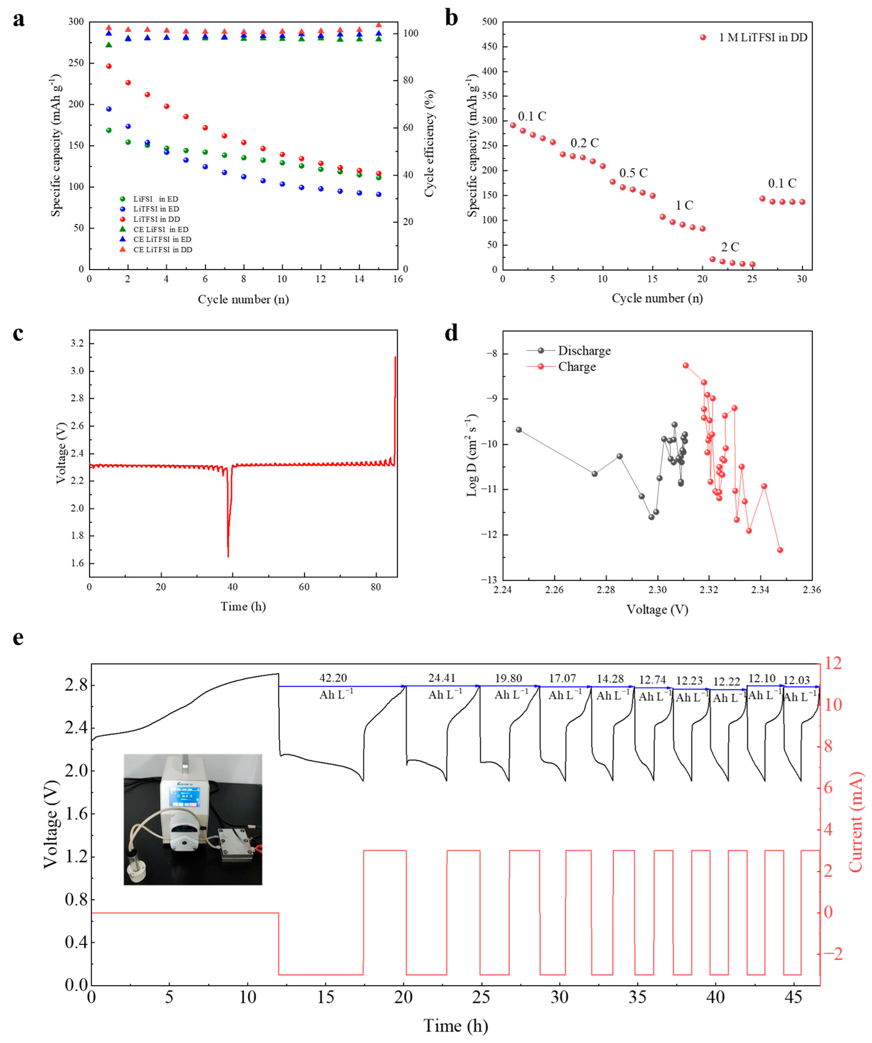
Three types of electrolytes were used to assemble slurry lithium half-cells, and their electrochemical performance was tested at a current density of 1.25 A g⁻1 (0.5 C) within a voltage range of 1.9–2.8 V. Figure 3a displays the cycling performance of the three different electrolyte systems during the initial 15 cycles. The initial specific capacities were measured as 246.2, 194.3, and 168.5 mAh g−1 for 1 M LiTFSI in DD, 1 M LiTFSI in ED, and 1 M LiFSI in ED, respectively. Notably, the 1 M LiTFSI in DD electrolyte exhibited significantly higher capacity compared to the other two electrolyte formulations, approaching the theoretical capacity of 257 mAh g−1. However, the capacity of all three slurry batteries decreased to 116, 90, and 111 mAh g−1 after 15 cycles. The rate performance of 1 M LiTFSI in DD slurry battery was tested at 0.25 A g−1 (0.1 C), 0.5 A g−1 (0.2 C), 1.25 A g−1 (0.5 C), 2.5 A g−1 (1 C), and 5.0 A g−1 (2 C) current densities. The specific capacities of 272.2, 226.6, 162.0, 91, and 21.5 mAh g−1 were expressed, respectively, as shown in Figure 3b. When the magnification test ended and returned to 0.1 C, the capacity was only 143.7 mAh g−1. Through the GITT test, the lithium-ion diffusion coefficient of the AQ slurry electrode for the 1 M LiTFSI in DD electrolyte is calculated. The GITT result and the lithium-ion diffusion coefficient value during the charge and discharge process are shown in Figure 3c,d. In the GITT test, AQ still expresses a stable voltage platform of 2.3 V vs. Li/Li+. It has a stable lithium-ion diffusion rate during the cycle. Based on the aforementioned tests, we identified 1 M LiTFSI in DD as the optimal electrolyte. Using this electrolyte formulation, we assembled a slurry reactor and conducted galvanostatic charge–discharge tests at 3 mA with a voltage window of 1.9–2.8 V vs. Li/Li+. Figure 3e presents the performance of the static AQ slurry reactor, demonstrating an initial volumetric specific capacity of 42.2 Ah L−1 in the first cycle and maintaining operation for 10 complete cycles (over 47 h). Notably, the slurry exhibited continuous capacity decay throughout these cycles, with the capacity declining to 12.03 Ah L−1 by the tenth cycle. For OEMs, the intrinsic origin of capacity fading lies in the reduction of redox-active functional groups. It is preliminarily inferred that the loss of active material loading leads to capacity degradation, which will be further elucidated in subsequent characterizations.
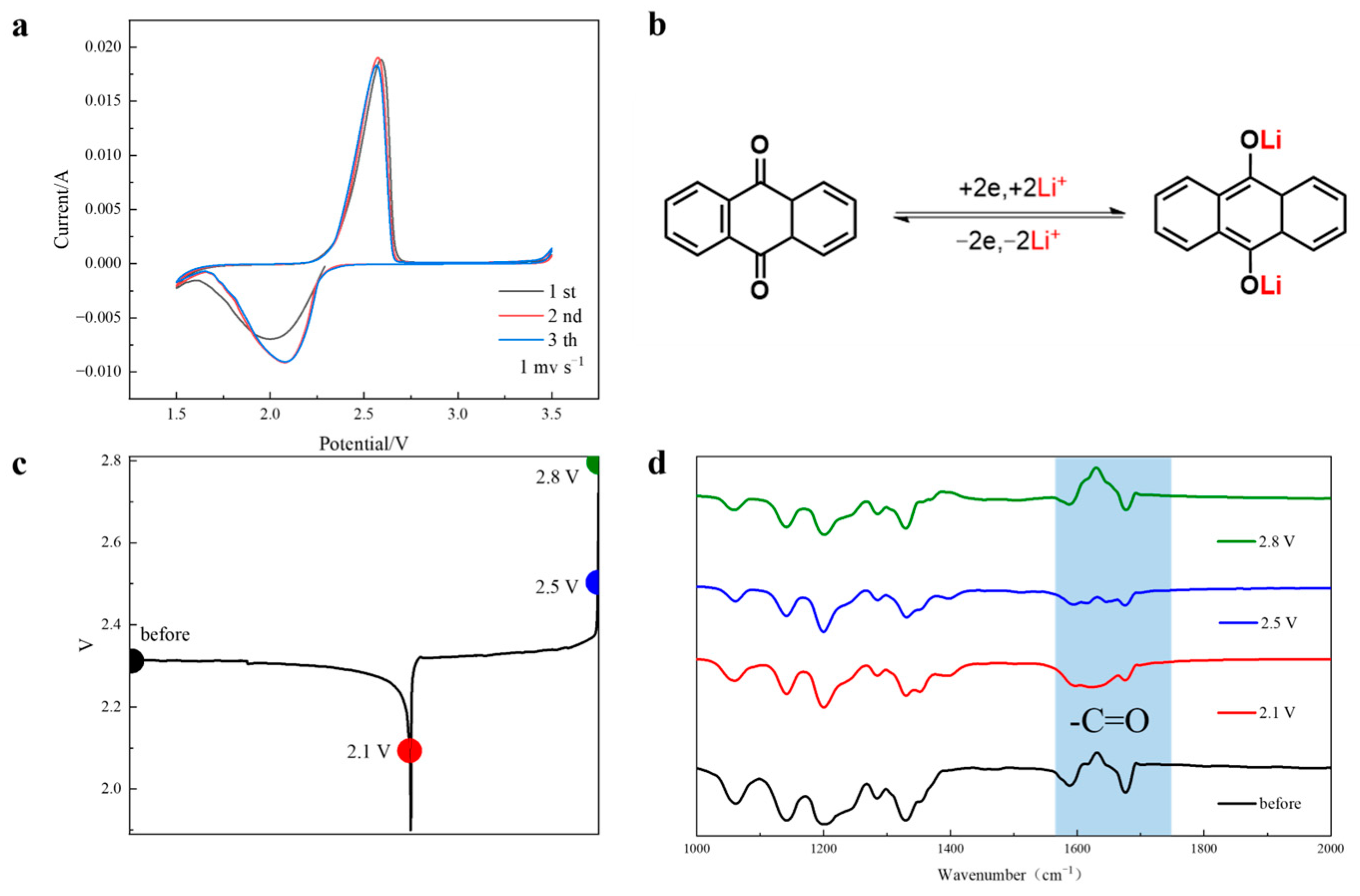
CV test was conducted on a slurry cell containing 1 M LiTFSI in the DD electrolyte at a scan rate of 1 mV s−1. As shown in Figure 4a, the CV curves exhibit highly reversible redox peaks at 2.57 V and 2.07 V, corresponding to the oxidation and reduction processes of carbonyl groups (-C=O) coupled with Li+ deintercalation and intercalation, respectively. Figure 4b schematically depicts the redox reaction mechanism of AQ. Figure 4c is the voltage curve of the first cycle of the AQ slurry battery. The FT-IR spectra obtained at different charge states clearly reveal the reversible redox behavior of carbonyl groups in the AQ material during electrochemical cycling in Figure 4d. As the slurry electrode discharges to 2.1 V, the characteristic carbonyl vibration peak progressively diminishes in intensity. Upon subsequent charging to 2.5 V, the peak intensity shows partial recovery, followed by complete restoration when reaching 2.8 V. This systematic variation in FT-IR spectral features provides direct spectroscopic evidence for the reversible electrochemical redox process involving the carbonyl functional groups of AQ.
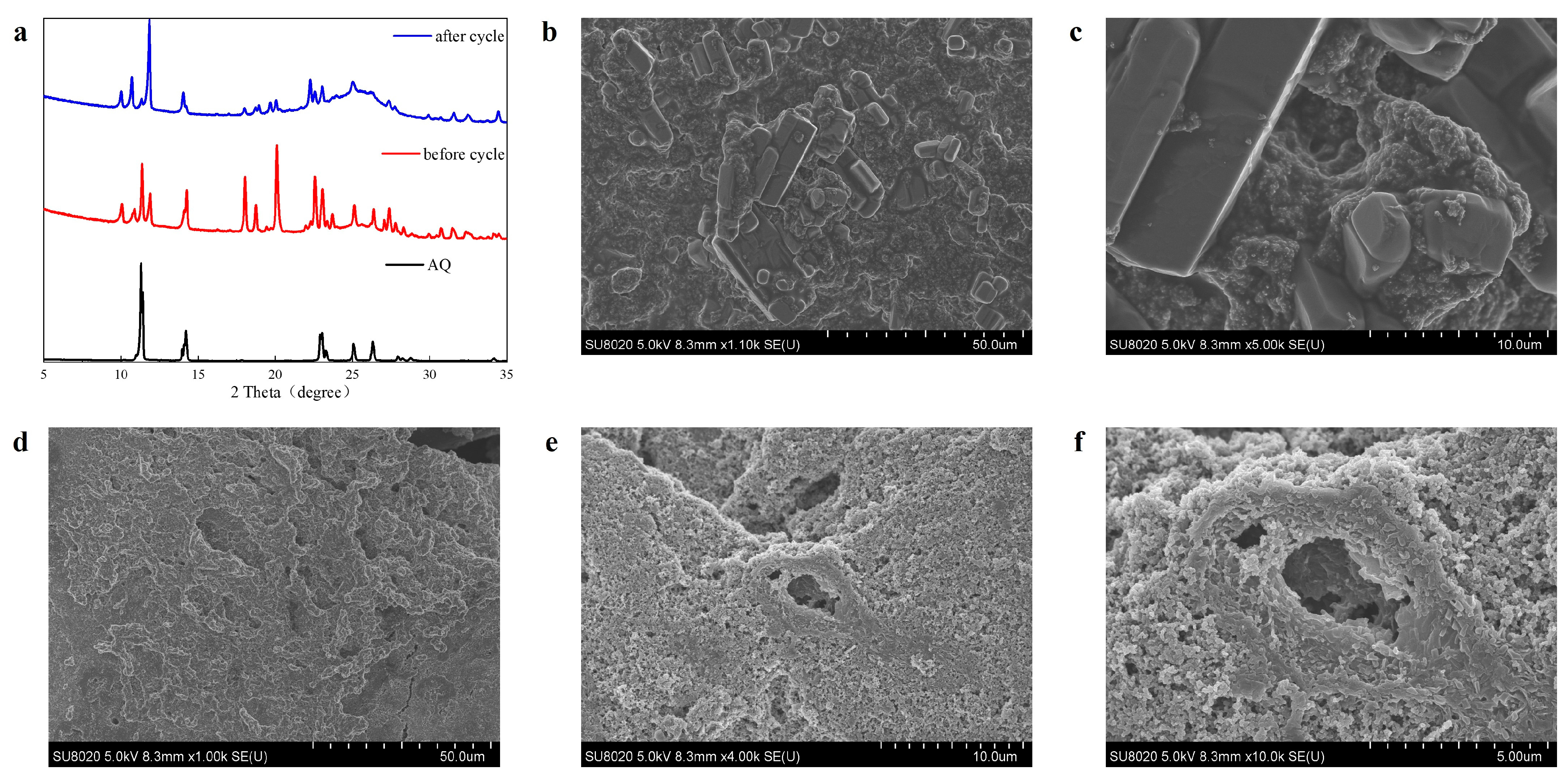
In Figure 5a, X-ray diffraction (XRD) results of AQ raw materials and AQ slurry before and after the cycle show that the intensity of the characteristic peak belonging to AQ at 2θ = 11.28° becomes lower before and after the cycle, and the characteristic peak at 2θ = 26.28° becomes a wide peak. Combining with the scanning electron microscopy (SEM) images of the slurry electrodes before and after cycling, Figure 5b,c reveals that the pristine electrode exhibits uniformly distributed rectangular AQ particles intimately contacting with KB carbon additives. In contrast, Figure 5d demonstrates the disappearance of distinct rectangular AQ particles in the cycled electrode. Figure 5e clearly shows the formation of irregular pores on the AQ material surface. The magnified image in Figure 5f distinctly reveals dissolution-generated cavities with irregular protrusions formed on their interior surfaces, demonstrating that the AQ material underwent partial dissolution during cycling, which consequently damaged its original rectangular morphology.
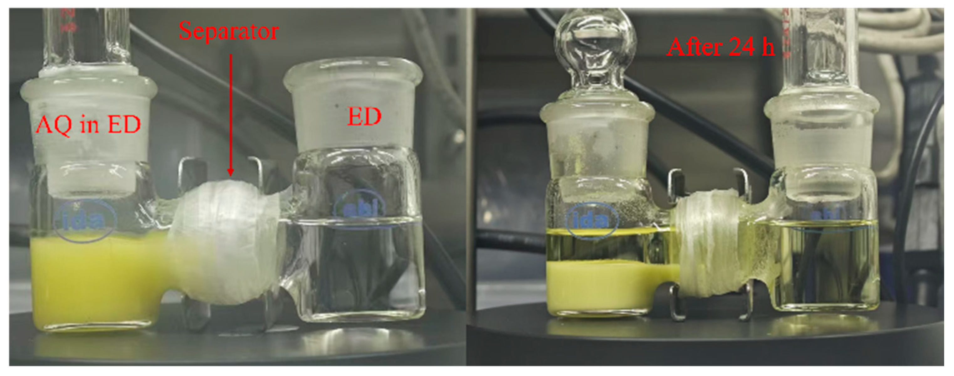
However, the dissolved AQ retains the essential characteristics of RFBs, and the crossover of electrode materials in RFBs is often an important factor causing the capacity attenuation of the battery [38]. Given that the first-cycle capacity of the AQ slurry cell approaches theoretical values, we attribute the observed capacity fading to crossover of dissolved AQ species across the separator. To verify this hypothesis, we conducted diffusion tests using an H-type diffusion cell (H-cell) apparatus. The cell was assembled with a Celgard 2320 separator, where one chamber contained AQ in ED (light yellow) and the other contained pure ED (colorless). Membrane permeability was evaluated by monitoring color changes in the ED chamber over 48 h. As shown in Figure 6, the initially colorless ED solution developed a distinct yellow coloration after 48 h, unambiguously confirming significant AQ crossover. These results demonstrate that the Celgard separator provides insufficient barrier properties against AQ species, and this substantial crossover directly correlates with the capacity decay observed in AQ slurry batteries. The crossover behavior induces a reduction in the active material loading at the electrode side, consequently diminishing the population of redox-active functional groups and ultimately leading to capacity fading of the battery.

4. Conclusions

Through comprehensive characterization, including cyclic voltammetry measurements, analysis of first-cycle charge/discharge profiles, ex situ FT-IR spectroscopy of electrodes discharged to 2.15 V (vs. Li/Li+), and monitoring of solvent FT-IR peak shifts after AQ dissolution in ED, we systematically evaluated the effects of different lithium salts and solvents on the electrochemical redox behavior of AQ electrodes. The 1 M LiTFSI in the DD electrolyte that could stabilize the AQ voltage platform was screened out, and the AQ slurry battery prepared with it could express the initial specific capacity of 246.2 mAh g−1 at a rate of 0.5 C, which was close to the theoretical specific capacity, with stable slurry reactor operation for over 47 h. The redox mechanism and lithium-ion diffusion coefficient of AQ slurry were studied. In order to solve the capacity attenuation problem of the AQ slurry battery, the crossover of AQ was confirmed by the diaphragm transmittance test, which caused serious capacity attenuation and affected the cycle stability of the AQ slurry battery. In summary, AQ is a potential negative electrode material for slurry batteries. It is necessary to find a diaphragm with multiple-choice permeability to AQ material to achieve stable circulation of the slurry battery.

Author Contributions

Conceptualization, methodology, software, validation, formal analysis, investigation, resources, data curation and writing—original draft preparation, C.Z.; writing—review and editing, T.H. All authors have read and agreed to the published version of the manuscript.

Funding

This work is financially supported by the Yunnan Young and Middle-aged Academic and Technical Leaders Reserve Talents Project (NO. 202005AC160033) and Ten Thousand Talent Plans for Young Top-notch Talents of Yunnan Province (NO. YNWRQNBJ-2019-222).

Data Availability Statement

The original contributions presented in this study are included in the article. Further inquiries can be directed to the corresponding author.

Conflicts of Interest

The authors declare no conflict of interest.

References

  1. Mousaei, A.; Naderi, Y.; Bayram, I.S. Advancing State of Charge Management in Electric Vehicles With Machine Learning: A Technological Review. IEEE Access 2024, 12, 43255–43283. [Google Scholar] [CrossRef]
  2. Xiao, S.; Chen, Y.; Zhou, X.; Sun, H.; Wan, W.; Li, Y.; Yao, R.; Bi, F.; Zhao, L.; Wang, L.; et al. Hierarchical Phosphide-Based Hybrid Anodes for High-Performance Lithium-Ion Batteries. Nano Lett. 2025, 25, 3532–3540. [Google Scholar] [CrossRef] [PubMed]
  3. Chen, B.; Zhang, Z.; Ji, Y.; Rao, X.; Xin, M.; Liu, B.; Xie, Z. A novel strategy toward high energy density: Liquid–solid two-phase chemical reaction in flow battery environment. Chem. Eng. Sci. 2025, 305, 121126. [Google Scholar] [CrossRef]
  4. Han, L.; Wang, L.; Chen, Z.; Kan, Y.; Hu, Y.; Zhang, H.; He, X. Incombustible Polymer Electrolyte Boosting Safety of Solid-State Lithium Batteries: A Review. Adv. Funct. Mater. 2023, 33, 2300892. [Google Scholar] [CrossRef]
  5. Zhang, H.; Peng, Y.; Hu, Y.; Pan, S.; Tang, S.; Luo, Y.; Liang, Y.; Liao, Y.; Lin, Y.; Zhang, K.; et al. Quantitative Analysis of Aging and Rollover Failure Mechanisms of Lithium-Ion Batteries at Accelerated Aging Conditions. Adv. Energy Mater. 2025, 2404997. [Google Scholar] [CrossRef]
  6. Wan, G.; Pollard, T.P.; Ma, L.; Schroeder, M.A.; Chen, C.-C.; Zhu, Z.; Zhang, Z.; Sun, C.-J.; Cai, J.; Thaman, H.L.; et al. Solvent-mediated oxide hydrogenation in layered cathodes. Science 2024, 385, 1230–1236. [Google Scholar] [CrossRef] [PubMed]
  7. Li, R.; Kirkaldy, N.D.; Oehler, F.F.; Marinescu, M.; Offer, G.J.; O’Kane, S.E.J. The importance of degradation mode analysis in parameterising lifetime prediction models of lithium-ion battery degradation. Nat. Commun. 2025, 16, 2776. [Google Scholar] [CrossRef]
  8. Cheng, S.; Jiang, L.; Wei, Z.; Meng, X.; Duan, Q.; Xiao, H.; Sun, J.; Wang, Q. Elucidating in-situ heat generation of LiFePO4 semi-solid lithium slurry battery under specific cycling protocols. Electrochim. Acta 2024, 475, 143674. [Google Scholar] [CrossRef]
  9. Luo, H.; Xiong, F.; Bai, H.; Wang, C.; Wang, Y.; Zhao, K.; Yan, J.; Zhang, Y.; Ding, J.; Wang, S.; et al. Multi-carbonyl naphthalene diimide polymer as a high-performance cathode for stable lithium-ion storage. Nano Res. Energy 2025, e9120159. [Google Scholar] [CrossRef]
  10. Zheng, M.; You, Y.; Lu, J. Understanding materials failure mechanisms for the optimization of lithium-ion battery recycling. Nat. Rev. Mater. 2025. [Google Scholar] [CrossRef]
  11. Bai, Q.; Huang, J.; Tang, K.; Zhu, Y.; Wu, D. Arylamine-Linked Porous Organic Polymers with Abundant Redox-Active Sites as High-Capacity and High-Rate Organic Cathodes for Lithium-Ion Batteries. Adv. Mater. 2025, 37, 2416661. [Google Scholar] [CrossRef] [PubMed]
  12. Wu, Y.; Ye, H.; Li, Y. Molecular Engineering of Organic Electrode Materials for Beyond Lithium-Ion Batteries. Adv. Funct. Mater. 2025, 2424329. [Google Scholar] [CrossRef]
  13. Wang, Y.; Zhu, Y.; Chen, Z.; Yang, X.; Zhang, R.; Wang, H.; Yang, Y. Molecule and Microstructure Modulations of Cyano-Containing Electrodes for High-Performance Fully Organic Batteries. Angew. Chem. Int. Ed. 2024, 63, e202401253. [Google Scholar] [CrossRef]
  14. Gao, H.; Zhu, Q.; Neale, A.R.; Bahri, M.; Wang, X.; Yang, H.; Liu, L.; Clowes, R.; Browning, N.D.; Sprick, R.S.; et al. Integrated Covalent Organic Framework/Carbon Nanotube Composite as Li-Ion Positive Electrode with Ultra-High Rate Performance. Adv. Energy Mater. 2021, 11, 2101880. [Google Scholar] [CrossRef]
  15. Wei, D.; Zhang, L.; Wang, Y.; Qiu, S.; Luo, Y.; Zou, Y.; Xu, F.; Sun, L.; Chu, H. Recent progress on construction and applications of metal-organic frameworks-based materials for lithium-ion batteries and supercapacitors. Carbon Neutralization 2024, 3, 396–414. [Google Scholar] [CrossRef]
  16. Chen, H.; Zhou, Y.; Lu, Y.-C. Lithium–Organic Nanocomposite Suspension for High-Energy-Density Redox Flow Batteries. ACS Energy Lett. 2018, 3, 1991–1997. [Google Scholar] [CrossRef]
  17. Zhao, Y.; Si, S.; Liao, C. A single flow zinc//polyaniline suspension rechargeable battery. J. Power Sources 2013, 241, 449–453. [Google Scholar] [CrossRef]
  18. Gautam, R.K.; McGrath, J.J.; Wang, X.; Jiang, J.J. Nonaqueous Organic Slurry Battery over 4 V. ACS Energy Lett. 2024, 9, 4408–4413. [Google Scholar] [CrossRef]
  19. Gan, X.; Song, Z. Small-molecule organic electrode materials for rechargeable batteries. Sci. China Chem. 2023, 66, 3070–3104. [Google Scholar] [CrossRef]
  20. Li, C.; Wang, D.-D.; Poon Ho, G.S.H.; Zhang, Z.; Huang, J.; Bang, K.-T.; Lau, C.Y.; Leu, S.-Y.; Wang, Y.; Kim, Y. Anthraquinone-Based Silicate Covalent Organic Frameworks as Solid Electrolyte Interphase for High-Performance Lithium–Metal Batteries. J. Am. Chem. Soc. 2023, 145, 24603–24614. [Google Scholar] [CrossRef]
  21. Wang, H.; Liu, G.; Zhou, W.; Wang, Y.; Dong, X. High-Potential and Stable Organic Cathode for Rechargeable Batteries with Fast-Charging and Wide-Temperature Adaptability. Angew. Chem. Int. Ed. 2025, 64, e202416874. [Google Scholar] [CrossRef] [PubMed]
  22. Zhang, K.; Guo, C.; Zhao, Q.; Niu, Z.; Chen, J. High-Performance Organic Lithium Batteries with an Ether-Based Electrolyte and 9,10-Anthraquinone (AQ)/CMK-3 Cathode. Adv. Sci. 2015, 2, 1500018. [Google Scholar] [CrossRef]
  23. Wang, C.; Yu, B.; Liu, Y.; Wang, H.; Zhang, Z.; Xie, C.; Li, X.; Zhang, H.; Jin, Z. N-alkyl-carboxylate-functionalized anthraquinone for long-cycling aqueous redox flow batteries. Energy Storage Mater. 2021, 36, 417–426. [Google Scholar] [CrossRef]
  24. Pan, S.; Yang, L.; Su, P.; Zhang, H.; Zhang, S. Robust Multiscale Electron/Ion Transport and Enhanced Structural Stability in SiO Semi-Solid Anolytes Enabled by Trifunctional Artificial Interfaces for High-Performance Li-Ion Slurry Flow Batteries. Small 2022, 18, 2202139. [Google Scholar] [CrossRef] [PubMed]
  25. Zhang, L.; Wu, X.; Qian, W.; Zhang, H.; Zhang, S. Lithium slurry flow cell, a promising device for the future energy storage. Green Energy Environ. 2021, 6, 5–8. [Google Scholar] [CrossRef]
  26. Xin, Y.; Ge, Y.; Li, Z.; Zhang, Q.; Tian, H. Research Progress on Modification Strategies of Organic Electrode Materials for Energy Storage Batteries. Acta Phys.-Chim. Sin. 2024, 40, 2303060. [Google Scholar] [CrossRef]
  27. Lu, Y.; Cai, Y.; Zhang, Q.; Chen, J. Insights into Redox Processes and Correlated Performance of Organic Carbonyl Electrode Materials in Rechargeable Batteries. Adv. Mater. 2022, 34, 2104150. [Google Scholar] [CrossRef]
  28. Gui, B.; Yang, X.; Fu, H.; Peng, P.; Lyu, W.; Rao, A.M.; Zhou, J.; Fan, L.; Lu, B. Synergistic Electrode and Electrolyte Polarities Lead to Outstanding Organic Potassium-based Batteries. Angew. Chem. Int. Ed. 2025, 64, e202421928. [Google Scholar] [CrossRef] [PubMed]
  29. Sun, T.; Zhang, W.; Shi, M.; Li, D.; Sun, Q.; Cheng, M.; Tao, Z. Intramolecular Hydrogen Bonds Weaken Interaction Between Solvents and Small Organic Molecules Towards Superior Lithium-Organic Batteries. Angew. Chem. Int. Ed. 2025, 64, e202416845. [Google Scholar] [CrossRef]
  30. Sun, T.; Feng, X.-L.; Sun, Q.-Q.; Yu, Y.; Yuan, G.-B.; Xiong, Q.; Liu, D.-P.; Zhang, X.-B.; Zhang, Y. Solvation Effect on the Improved Sodium Storage Performance of N-Heteropentacenequinone for Sodium-Ion Batteries. Angew. Chem. Int. Ed. 2021, 60, 26806–26812. [Google Scholar] [CrossRef]
  31. Cai, T.; Han, Y.; Lan, Q.; Wang, F.; Chu, J.; Zhan, H.; Song, Z. Stable cycling of small molecular organic electrode materials enabled by high concentration electrolytes. Energy Storage Mater. 2020, 31, 318–327. [Google Scholar] [CrossRef]
  32. Li, Y.; Lu, Y.; Ni, Y.; Zheng, S.; Yan, Z.; Zhang, K.; Zhao, Q.; Chen, J. Quinone Electrodes for Alkali–Acid Hybrid Batteries. J. Am. Chem. Soc. 2022, 144, 8066–8072. [Google Scholar] [CrossRef]
  33. Yao, Y.-X.; Chen, X.; Yan, C.; Zhang, X.-Q.; Cai, W.-L.; Huang, J.-Q.; Zhang, Q. Regulating Interfacial Chemistry in Lithium-Ion Batteries by a Weakly Solvating Electrolyte. Angew. Chem. Int. Ed. 2021, 60, 4090–4097. [Google Scholar] [CrossRef]
  34. Zhang, Y.; Katayama, Y.; Tatara, R.; Giordano, L.; Yu, Y.; Fraggedakis, D.; Sun, J.G.; Maglia, F.; Jung, R.; Bazant, M.Z.; et al. Revealing electrolyte oxidation via carbonate dehydrogenation on Ni-based oxides in Li-ion batteries by in situ Fourier transform infrared spectroscopy. Energy Environ. Sci. 2020, 13, 183–199. [Google Scholar] [CrossRef]
  35. Wang, J.; Luo, J.; Wu, H.; Yu, X.; Wu, X.; Li, Z.; Luo, H.; Zhang, H.; Hong, Y.; Zou, Y.; et al. Visualizing and Regulating Dynamic Evolution of Interfacial Electrolyte Configuration during De-solvation Process on Lithium-Metal Anode. Angew. Chem. Int. Ed. 2024, 63, e202400254. [Google Scholar] [CrossRef] [PubMed]
  36. Wang, Y.; Cao, Z.; Ma, Z.; Liu, G.; Cheng, H.; Zou, Y.; Cavallo, L.; Li, Q.; Ming, J. Weak Solvent–Solvent Interaction Enables High Stability of Battery Electrolyte. ACS Energy Lett. 2023, 8, 1477–1484. [Google Scholar] [CrossRef]
  37. Piao, Z.; Gao, R.; Liu, Y.; Zhou, G.; Cheng, H.-M. A Review on Regulating Li+ Solvation Structures in Carbonate Electrolytes for Lithium Metal Batteries. Adv. Mater. 2023, 35, 2206009. [Google Scholar] [CrossRef]
  38. Wang, Y.; Mu, A.; Wang, W.; Yang, B.; Wang, J. A Review of Capacity Decay Studies of All-vanadium Redox Flow Batteries: Mechanism and State Estimation. ChemSusChem 2024, 17, e202301787. [Google Scholar] [CrossRef]
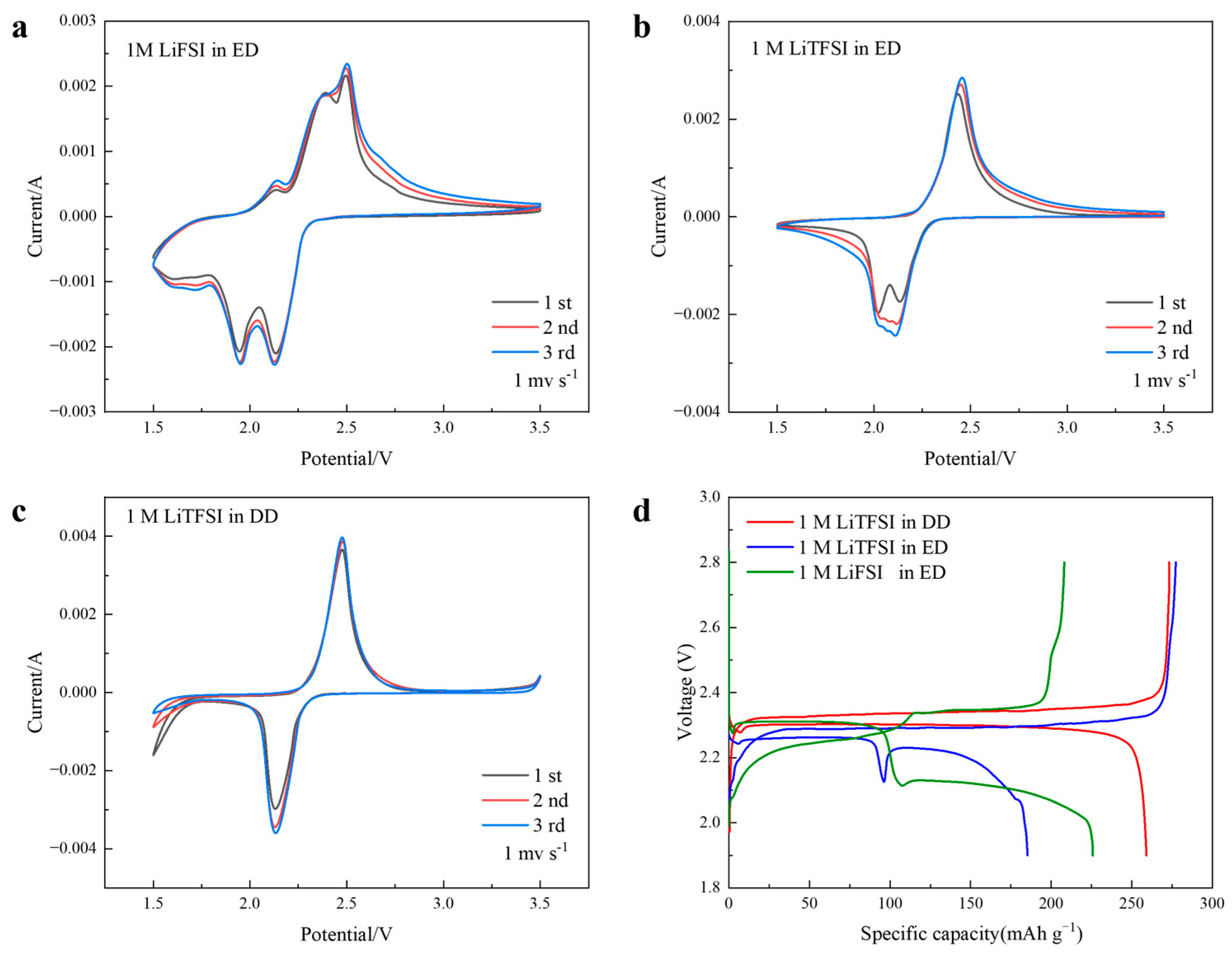
Figure 1. CV curves of batteries in different electrolytes, (a) 1 M LiFSI in ED, (b) 1 M LiTFSI in ED, (c) 1 M LiTFSI in DD, and (d) First cycle voltage capacity curves of different electrolyte batteries.
Processes 13 01403 g001
Figure 2. (a) FT-IR with different lithium electrolyte electrodes discharged to 2.15 V and (b) FT-IR comparison of AQ dissolved in ED, pure ED solvent, and AQ.
Processes 13 01403 g002
Figure 3. (a) The 0.5 C cycle performance of three kinds of electrolyte slurry batteries, (b) Rate capability of 1 M LiTFSI in DD electrolyte slurry battery, (c) GITT, (d) Charge and discharge process of DLi, and (e) Slurry static reactor performance.
Processes 13 01403 g003
Figure 4. (a) CV curve of slurry battery, (b) Schematic diagram of AQ redox mechanism, (c) AQ first cycle potentiogram, and (d) FT-IR.
Processes 13 01403 g004
Figure 5. (a) XRD before and after the cycle, (b,c) SEM of slurry before circulation, and (df) Slurry SEM after circulation.
Processes 13 01403 g005
Figure 6. H-type diffusion cell test standing for 48 h.
Processes 13 01403 g006
Table 1. Abbreviations and their corresponding full terms.
AbbreviationsTerminology
RFBsredox flow batteries
LIBslithium-ion batteries
SLBssemi-solid lithium slurry batteries
OEMsorganic electrode materials
AQanthraquinone
LiFSIlithium bisfluorosulfonimide
LiTFSIlithium bis(trifluoromethanesulphonyl)imide
ECethylene carbonate
DMCdimethyl carbonate
EDEC/DMC; 3:7 by mass
DMEglycol dimethyl ether
DOL1,3-dioxolane
DDDME/DOL; 1:1 by volume
KBKetjenblack
PVDFpolyvinylidene fluoride
NMPN-methylpyrrolidone
TX-100Triton X-100
CCcarbon cloth
GITTGalvanostatic Intermittent Titration Technique
CVcyclic voltammetry
H-cellH-type diffusion cell
Disclaimer/Publisher’s Note: The statements, opinions and data contained in all publications are solely those of the individual author(s) and contributor(s) and not of MDPI and/or the editor(s). MDPI and/or the editor(s) disclaim responsibility for any injury to people or property resulting from any ideas, methods, instructions or products referred to in the content.